Ubiquiti Networks AF4X Dual Channel OFDM MIMO Point to Point Device User Manual airFiber X User Guide
Ubiquiti Networks, Inc. Dual Channel OFDM MIMO Point to Point Device airFiber X User Guide
Contents
- 1. Users Manual pt 1
- 2. Users Manual pt 2
- 3. Users Manual pt 3
- 4. Users Manual pt 4
- 5. Users Manual pt 5
Users Manual pt 4
35
Chapter 10: ToolsairFiber X User Guide
Ubiquiti Networks, Inc.
Chapter 10: Tools
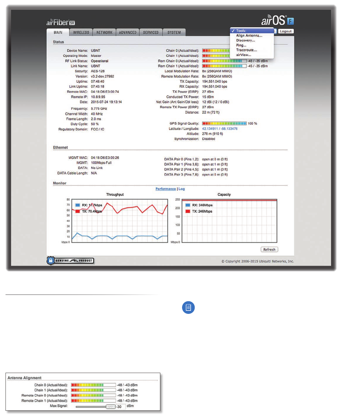
Each tab of the airFiber Configuration Interface contains
network administration and monitoring tools. Click the
Tools drop‑down list at the top right corner of the page.
Align Antenna
Use the Align Antenna tool to point and optimize the
antenna in the direction of maximum link signal. The
Antenna Alignment window is designed to refresh every
250 milliseconds.
Chain 0/1 (Actual/Ideal) Displays the absolute power
level (in dBm) of the received signal for each chain.
Note: If “Overload” is displayed to indicate an
overload condition, identify and eliminate any
sources of strong in‑band interference.
Remote Chain 0/1 (Actual/Ideal) Displays the absolute
power level (in dBm) of the received signal for each chain
of the remote airFiberX radio.
Max Signal Displays the maximum signal strength (in
dBm). To adjust the range of the Max Signal meter, use
the slider or manually enter the new value. If you reduce
the range, the color change will be more sensitive to
signal fluctuations, indicating the offset of the maximum
indicator value and the scale itself.
36
Chapter 10: Tools airFiber X User Guide
Ubiquiti Networks, Inc.
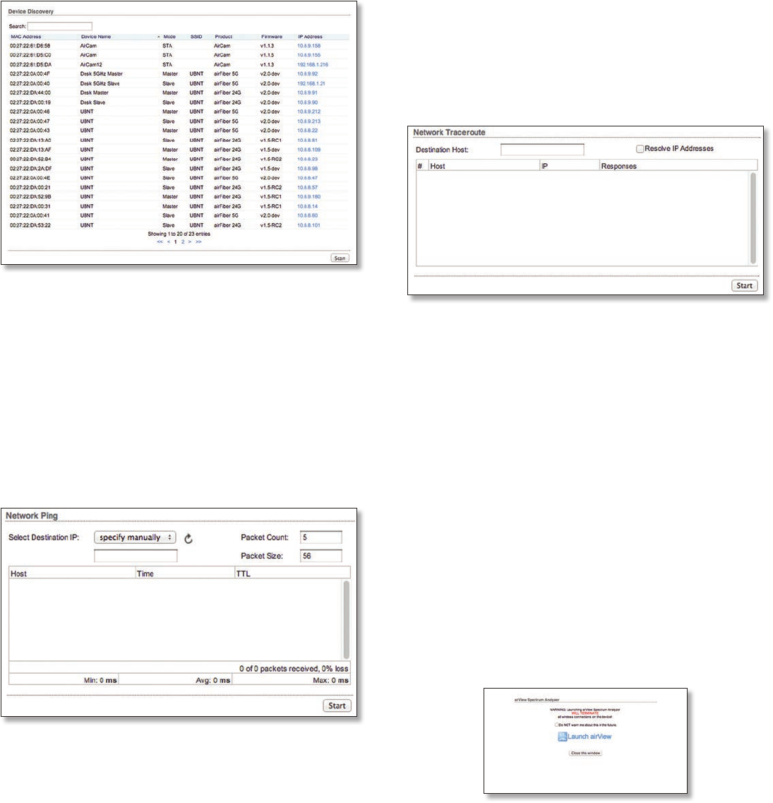
Discovery
The Device Discovery tool searches for all Ubiquiti devices
on your network. The Search field automatically filters
devices containing specified names or numbers as you
enter them.
It reports the MAC Address, Device Name, Mode, SSID,
Product type, Firmware version, and IP Address for each
Ubiquiti device. To access a device configuration through
its web management interface, click the device’s IP
address.
To refresh the window, click Scan.
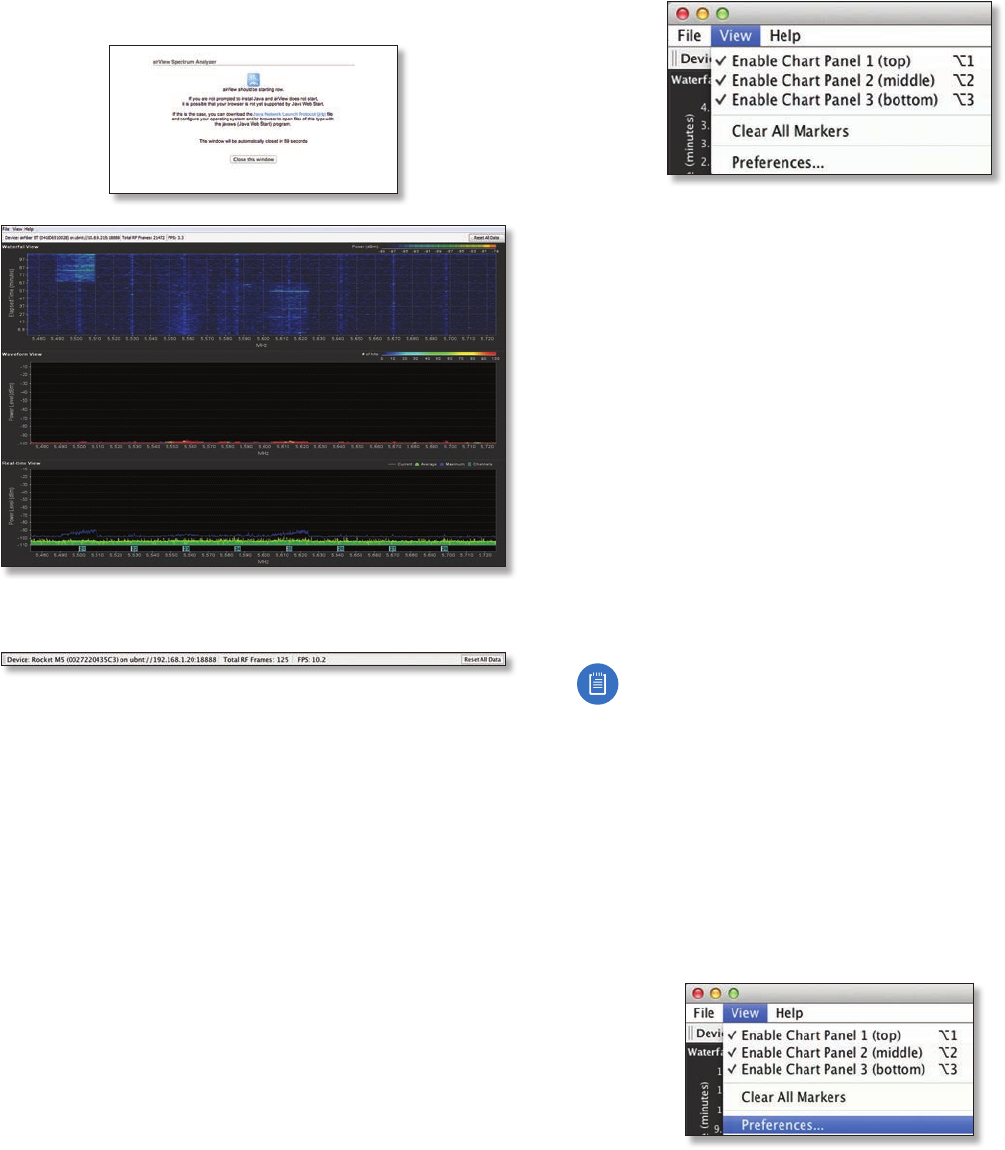
Ping
You can ping other devices on the network directly from
the airFiberX radio. The Ping tool uses ICMP packets to
check the preliminary link quality and packet latency
estimation between two network devices.
Network Ping
Select Destination IP You have two options:
• Select a remote system IP from the drop‑down list,
which is generated automatically.
• Select specify manually and enter the IP address in the
field displayed below the option.
Packet Count Enter the number of packets to send for
the ping test.
Packet Size Specify the size of the packet.
Start Click this button to start the test.
Packet loss statistics and latency time evaluation are
displayed after the test is completed.
Traceroute
The Traceroute tool traces the hops from the airFiberX
radio to a specified outgoing IP address. Use this tool to
find the route taken by ICMP packets across the network
to the destination host.
Destination Host Enter the IP address of the
destinationhost.
Resolve IP Addresses Select this option to resolve the IP
addresses symbolically rather than numerically.
Start Click this button to start the test.
Responses are displayed after the test is completed.
airView
Use the airView Spectrum Analyzer to analyze the noise
environment of the radio spectrum and intelligently select
the optimal frequency to install a PtP airFiber link.
There are two system requirements for the airView
Spectrum Analyzer:
• Your system is connected to the device via Ethernet.
Launching airView will terminate all wireless
connections on the device.
• Java Runtime Environment 1.6 (or above) is required on
your client machine to use airView.
On first use, the following window appears.
• Do NOT warn me about this in the future Check the
box to bypass this window in future launches of the
airView Spectrum Analyzer.
37
Chapter 10: ToolsairFiber X User Guide
Ubiquiti Networks, Inc.
• Launch airView Click Launch airView to download the
Java Network Launch Protocol (jnlp) file and complete
the launch of airView.
Main View
Device Displays the device name, MAC (Media Access
Control) address, and IP address of the device running
airView.
Total RF Frames Displays the total number of Radio
Frequency (RF) frames gathered since the start of the
airView session or since the Reset All Data button was last
clicked.
FPS Displays the total number of frames per second (FPS)
gathered since the start of the airView session or since
the Reset All Data button was last clicked. The wider the
interval amplitude, the fewer the FPS will be gathered.
Reset All Data Click to reset all gathered data. Use this
option to analyze the spectrum for another location or
address.
File Menu
Click Exit to end the airView session.
View Menu
Enable Chart Panel 1 (top) Displays the Waterfall or
Channel Usage chart in Chart Panel 1, depending on
which option you have selected in Preferences. This
time‑based graph shows the aggregate energy collected
or channel usage for each frequency since the start of the
airView session.
Enable Chart Panel 2 (middle) Displays the Waveform
chart in Chart Panel 2. This time‑based graph shows the RF
signature of the noise environment since the start of the
airView session. The energy color designates its amplitude.
Cooler colors represent lower energy levels (with blue
representing the lowest levels) in that frequency bin, and
warmer colors (yellow, orange, or red) represent higher
energy levels in that frequency bin.
Enable Chart Panel 3 (bottom) Displays the Real‑time
chart (traditional spectrum analyzer) in Chart Panel 3.
Energy (in dBm) is shown in real time as a function of
frequency.
Note:
Energy is the power ratio in decibels (dB) of the
measured power referenced to one milliwatt (mW).
Clear All Markers Resets all previously assigned
markers. Markers are assigned by clicking a point, which
corresponds with a frequency on the Real‑time chart.
Preferences Changes airView settings, such as enabling
or disabling charts and traces, or specifying the frequency
interval.
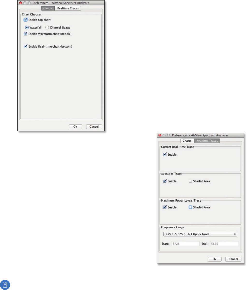
Preferences
Select View > Preferences to display the Preferences -
airView Spectrum Analyzer window.
38
Chapter 10: Tools airFiber X User Guide
Ubiquiti Networks, Inc.
Charts
Enable top chart Check the box to enable the top chart.
Select the desired chart to display in the top chart panel
on the main view. There are two options:
• Waterfall This time‑based graph shows the aggregate
energy collected for each frequency since the start
of the airView session. The energy color designates
its amplitude. Cooler colors represent lower energy
levels (with blue representing the lowest levels)
in that frequency bin, and warmer colors (yellow,
orange, or red) represent higher energy levels in that
frequencybin.
The Waterfall View’s legend (top‑right corner) provides
a numerical guide associating the various colors to
power levels (in dBm). The low end of that legend (left)
is always adjusted to the calculated noise floor, and the
high end (right) is set to the highest detected power
level since the start of the airView session.
• Channel Usage For each channel, a bar displays a
percentage showing the relative “crowdedness” of
that specific channel. To calculate this percentage, the
airView Spectrum Analyzer analyzes both the popularity
and strength of RF energy in that channel since the start
of an airView session.
Note: airFiberX radio channels are not related
to Wi‑Fi channels which are determined by IEEE
standards. airFiberX radio channels are numbered
consecutively starting with 0 and are 28 MHz in
width.
Enable Waveform chart (middle) Check the box to
enable the middle chart. This time‑based graph shows
the RF signature of the noise environment since the
start of the airView session. The energy color designates
its amplitude. Cooler colors represent lower energy
levels (with blue representing the lowest levels) in that
frequency bin, and warmer colors (yellow, orange, or red)
represent higher energy levels in that frequency bin.
The spectral view over time will display the steady‑state RF
energy signature of a given environment.
Enable Real-time chart (bottom) Check the box to
enable the bottom chart. This graph displays a traditional
spectrum analyzer in which energy (in dBm) is shown in
real time as a function of frequency. There are three traces
in this view:
• Current (Yellow) Shows the real‑time energy seen by
the device as a function of frequency.
• Average (Green) Shows the running average energy
across frequency.
• Maximum (Blue) Shows updates and maximum power
levels across frequency.
Real-Time Traces
The following settings apply only to the Real-time chart:
Current Real-time Trace Check the Enable box to enable
the real‑time trace. When enabled, the yellow outline on
the Real-time chart represents the real‑time power level of
each frequency. The refresh speed depends on the FPS.
39
Chapter 10: ToolsairFiber X User Guide
Ubiquiti Networks, Inc.
Averages Trace Check the Enable box to enable the
averages trace. When enabled, the averages trace is
represented by the green area on the Real-time chart,
which displays the average received power level data
since the start of the airView session. To enable a shaded
green area, check the Shaded Area box. To display only
a green outline without the shaded area, uncheck the
Shaded Area box.
Maximum Power Levels Trace Check the Enable box to
enable the maximum power trace. When enabled, the
maximum power trace is represented by the blue area on
the Real-time chart, which displays the maximum received
power level data since the start of the airView session. To
enable a shaded blue area, check the Shaded Area box.
To display only a blue outline without the shaded area,
uncheck the Shaded Area box.
Frequency Range Select the amplitude of the
frequency interval to be scanned from the Frequency
Range drop‑down list. Available frequencies are device‑
dependent. There are pre‑defined ranges for the most
popular bands. You can enter a custom range; select
Custom Range from the Frequency Range drop‑down list
and enter the desired values in the Start and End fields.
40
Chapter 10: Tools airFiber X User Guide
Ubiquiti Networks, Inc.
41
Appendix A: SpecificationsairFiber X User Guide
Ubiquiti Networks, Inc.
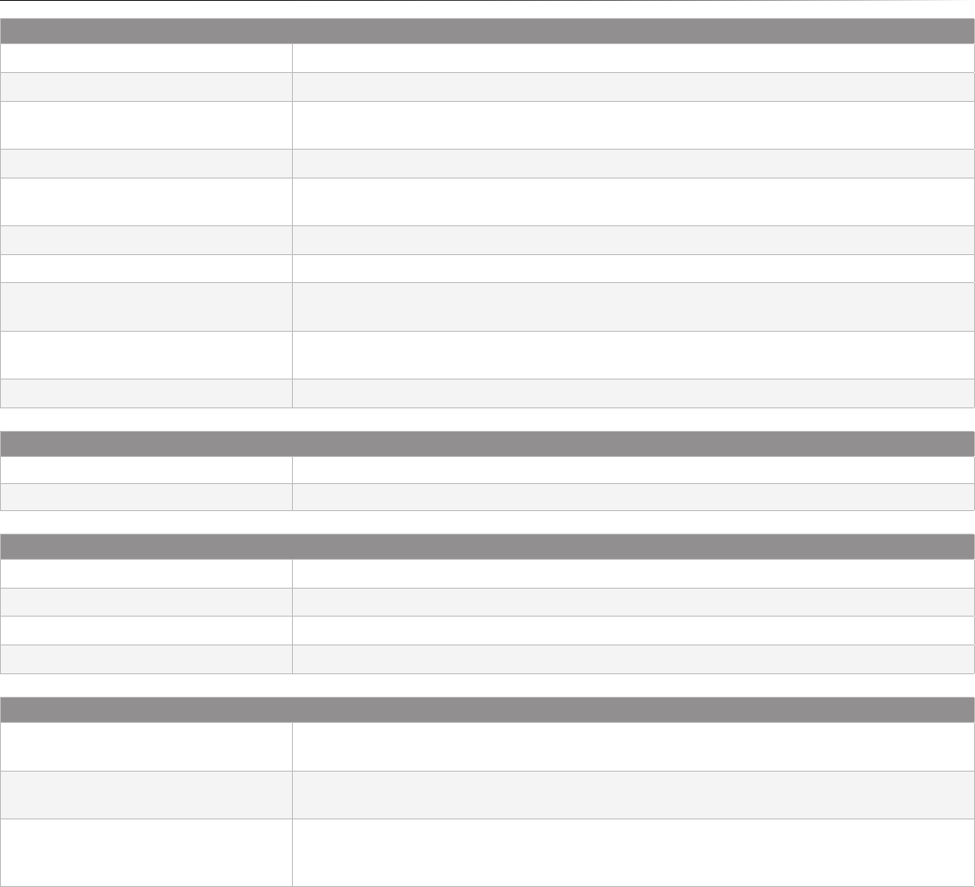
Appendix A: Specifications
airFiber AF‑2X
Dimensions 224 x 82 x 48 mm (8.82 x 3.23 x 1.89")
Weight 0.35 kg (0.77 lb)
RF Connectors (2) RP‑SMA Weatherproof (CH0, CH1)
(1) SMA Weatherproof (GPS)
GPS Antenna External, Magnetic Base
Max. Conducted TX Power 29 dBm
(Depends on Regulatory Region)
Power Supply 24V, 1A PoE Gigabit Adapter (Included)
Power Method Passive Power over Ethernet
Mounting Rocket Mount Compatible
GPS Pole Mount (Included)
Certications FCC Part 15.247
CE EN 300328 v1.8.1
Operating Temperature ‑40 to 55° C (‑40 to 131° F)
AF‑2X Networking Interface
Data Port (1) 10/100/1000 Ethernet Port
Management Port (1) 10/100 Ethernet Port
AF‑2X System Interface
Maximum Throughput 500 Mbps
Encryption 128‑bit AES
OS airOS F
Wireless Modes Master/Slave
AF‑2X Radio Interface
Operating Frequency 2400‑2500 MHz
(Depends on Regulatory Region)
Frequency Accuracy ± 2.5 ppm without GPS Synchronization
± 0.2 ppm with GPS Synchronization
Channel Bandwidth 3.5 MHz, 5 MHz, 7.0 MHz, 10 MHz, 14 MHz, 20 MHz, 28 MHz, 30 MHz, 40 MHz, 50 MHz,
and 56MHz Selectable
Programmable Uplink and Downlink Duty Cycles

42
Appendix A: Specifications airFiber X User Guide
Ubiquiti Networks, Inc.
airFiber AF‑3X
Dimensions 224 x 82 x 48 mm (8.82 x 3.23 x 1.89")
Weight 0.35 kg (0.77 lb)
RF Connectors (2) RP‑SMA Weatherproof (CH0, CH1)
(1) SMA Weatherproof (GPS)
GPS Antenna External, Magnetic Base
Max. Conducted TX Power 29 dBm
(Depends on Regulatory Region)
Power Supply 24V, 1A PoE Gigabit Adapter (Included)
Power Method Passive Power over Ethernet
Mounting Rocket Mount Compatible
GPS Pole Mount (Included)
Certications FCC Part 90 Z
CE EN 302 217‑2‑2
Operating Temperature ‑40 to 55° C (‑40 to 131° F)
AF‑3X Networking Interface
Data Port (1) 10/100/1000 Ethernet Port
Management Port (1) 10/100 Ethernet Port
AF‑3X System Interface
Maximum Throughput 500 Mbps
Encryption 128‑bit AES
OS airOS F
Wireless Modes Master/Slave
AF‑3X Radio Interface
Operating Frequency 3300‑3900 MHz
(Depends on Regulatory Region)
Frequency Accuracy ± 2.5 ppm without GPS Synchronization
± 0.2 ppm with GPS Synchronization
Channel Bandwidth 3.5 MHz, 5 MHz, 7.0 MHz, 10 MHz, 14 MHz, 20 MHz, 28 MHz, 30 MHz, 40 MHz, 50 MHz,
and 56MHz Selectable
Programmable Uplink and Downlink Duty Cycles

43
Appendix A: SpecificationsairFiber X User Guide
Ubiquiti Networks, Inc.
airFiber AF‑5X
Dimensions 224 x 82 x 48 mm (8.82 x 3.23 x 1.89")
Weight 0.35 kg (0.77 lb)
RF Connectors (2) RP‑SMA Weatherproof (CH0, CH1)
(1) SMA Weatherproof (GPS)
GPS Antenna External, Magnetic Base
Max. Conducted TX Power 26 dBm
(Depends on Regulatory Region)
Power Supply 24V, 1A PoE Gigabit Adapter (Included)
Power Method Passive Power over Ethernet
Mounting Rocket Mount Compatible
GPS Pole Mount (Included)
Certications FCC Part 15.407
CE EN 302502 v1.2.1, EN 301 893 v1.7.1
Operating Temperature ‑40 to 55° C (‑40 to 131° F)
AF‑5X Networking Interface
Data Port (1) 10/100/1000 Ethernet Port
Management Port (1) 10/100 Ethernet Port
AF‑5X System Interface
Maximum Throughput 500 Mbps
Encryption 128‑bit AES
OS airOS F
Wireless Modes Master/Slave
AF‑5X Radio Interface
Operating Frequency 5150‑5950 MHz
(Depends on Regulatory Region)
Frequency Accuracy ± 2.5 ppm without GPS Synchronization
± 0.2 ppm with GPS Synchronization
Channel Bandwidth 10 MHz, 20 MHz, 30 MHz, 40 MHz, 50 MHz Selectable
Programmable Uplink and Downlink Duty Cycles
44
Appendix A: Specifications airFiber X User Guide
Ubiquiti Networks, Inc.
45
Appendix B: AF-5X and airFiber MultiplexerairFiber X User Guide
Ubiquiti Networks, Inc.
Appendix B: AF-5X and
airFiber Multiplexer
Note: This appendix applies to the airFiber AF-5X
radio when used with the airFiber NxN Multiplexer.
The following provides important information for using
the AF-5X radio with the airFiber NxN Multiplexer (models
AF-MPx4 or AF-MPx8). For a successful deployment,
ensure that all additional steps are taken and that all
information is taken into consideration.
• During initial configuration of each AF-5X radio, input
the additional cable loss associated with the multiplexer,
and enable the NxN Radio setting. For details, refer to
Step 6 of “airFiber Configuration” on page4.
• When performing antenna alignment, perform the
procedure in “Establishing a Link” on page9 on
one radio only. This will help ensure maximum success
in registrations.
• After the first radio has been aligned with the other side
of the link, ensure that the TX power balance is present.
• To maintain 8x performance, maximum TX power
should not exceed 19-20 dBm.
• If 8x performance cannot be achieved at these TX power
levels, it may be possible to improve performance by
increasing channel spacing.
airFiber X Compatibility
The airFiber NxN is designed for use with airFiber 5X
radios, (model AF-5X) and 5 GHz airFiber X or RocketDish™
antennas.
Note: The airFiber X Antenna OMT Conversion Kit
(AF-5G-OMT-S45) is highly recommended when
using a RocketDish for proper fitting and improved
frequency isolation.
Installation Requirements
• (2) airFiber 5X radios for AF-MPx4
• (4) airFiber 5X radios for AF-MPx8
• airFiber X or RocketDish antenna
• Clear view of the sky for proper GPS operation
• Ground wires – min. 10 AWG (5 mm2) and max. length:
1m. Asa safety precaution, ground the airFiber radios to
grounded masts, poles, towers, or grounding bars.
WARNING: Failure to properly ground your
airFiber radio will void your warranty.
Note: For guidelines about grounding and
lightning protection, follow your local electrical
regulatorycodes.
• Outdoor, shielded Category 6 (or above) cabling and
shielded RJ-45 connectors are required for all wired
Ethernetconnections.
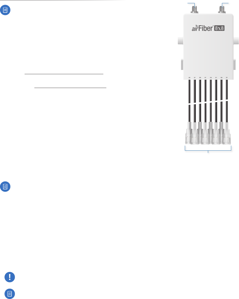
Hardware Overview
airFiber NxN Multiplexer
Chain 0 Chain 1
RF Cables
(AF-MPx8 Shown)
Chain 0 Connect the antenna RF +45° to this connector.
Chain 1 Connect the antenna RF -45° to this connector.
RF Cables Connect each RF Cable pair to the
corresponding RFconnection chain on each airFiber 5X
radio. For example, connect cable A0 to Chain 0, and
cable A1 to Chain 1.
46
Appendix B: AF-5X and airFiber Multiplexer airFiber X User Guide
Ubiquiti Networks, Inc.
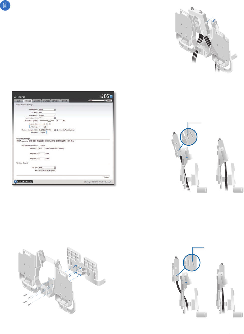
Configure the airFiber 5X Radio
Note: The airFiber 5X radios must be running
airOS®F v3.2.1 or newer. The latest firmware is
available at: downloads.ubnt.com/airfiber
Each airFiber 5X radio must be preconfigured for use with
the airFiberNxN before installing them at the site.
Enable airFiber NxN support on each radio:
1. Log into the airOS F Configuration Interface.
2. Click the Wireless tab.
3. Enter the additional Cable Loss value (dB):
a. 4.1 for the AF-MPx4, or
b. 7.2 for the AF-MPx8
4. For the NxN Radio setting, select Enable.
5. Click Change, and then click Apply.
Hardware Installation
The following installation shows the AF-MPx8. For the
AF-MPx4 installation, only the mounting and connecting
of two airFiber 5X radios apply.
1. (For AF-MPx8 only) Attach the 8x8 Radio Bracket to the
4x4 Radio Bracket using four M3x8 Screws.
2. Seat the airFiber NxN Multiplexer into the 4x4 Radio
Bracket either at (a) a 15° angle or (b) vertically:
a. For most antenna models, the airFiber NxN
Multiplexer should be installed at a 15° angle. Insert
the airFiber NxN Multiplexer from behind the 4x4
Radio Bracket and slide the 15° Angle Tabs into the
slots on the bracket.
15° Angle Tab
b. For other antenna configurations that require the
airFiber NxN assembly to be mounted to a pole, the
airFiber NxN Multiplexer must be installed vertically.
Insert the airFiber NxN Multiplexer from behind the
4x4 Radio Bracket and slide the Vertical Tabs into the
slots on the bracket.
Vertical Tab
47
Appendix B: AF-5X and airFiber MultiplexerairFiber X User Guide
Ubiquiti Networks, Inc.
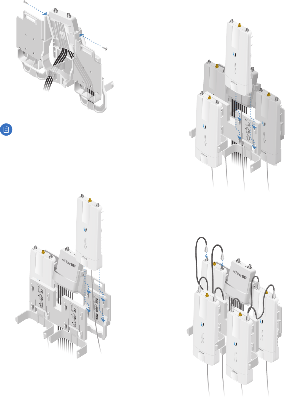
3. Secure the airFiber NxN Multiplexer to the 4x4 Radio
Bracket using two M4x12 Screws.
Note: Ensure the airFiber 5X radios are
preconfigured and the ground wires are installed
as outlined in the radio’s Quick Start Guide
before mounting the radios.
4. Mount the airFiber 5X radios to the 4x4 Radio Bracket:
a. Align the mounting tabs on the back of the radio
with the mounting bracket.
b. Slide the radio down to lock it into place.
Ubiquiti Networks, Inc. www.ubnt.com
Ubiquiti Networks, Inc. www.ubnt.com
5. Mount the airFiber 5X radios to the 8x8 Radio Bracket:
a. Align the mounting tabs on the back of the radio
with the mounting bracket.
b. Slide the radio down to lock it into place.
Ubiquiti Networks, Inc. www.ubnt.com
Ubiquiti Networks, Inc. www.ubnt.com
6. Connect the RF Cables to the airFiber 5X radios.
Connect each RF Cable pair to the corresponding
RFconnection chain on each radio. For example,
connect cable A0 to Chain 0, and cable A1 to Chain 1.
48
Appendix B: AF-5X and airFiber Multiplexer airFiber X User Guide
Ubiquiti Networks, Inc.
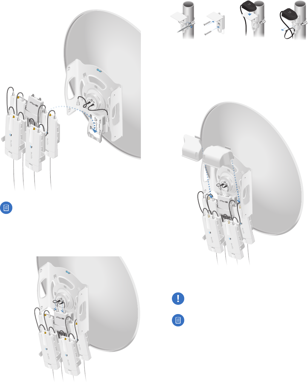
7. Attach the airFiber NxN assembly to the airFiber X or
RocketDish antenna:
a. Align the mounting tabs on the back of the airFiber
NxN Multiplexer with the mounting bracket.
b. Slide the airFiber NxN Multiplexer down to lock it into
place on the bracket.
Note: The airFiber NxN assembly may be
pole-mounted if it cannot be attached to the
antenna. See the Pole-Mounting section for
details.
8. Connect the RF cables from the antenna to the RF
connectors on the airFiber NxN Multiplexer. Connect
+45° to Chain 0 and -45° to Chain 1.
9. Attach the GPS antennas to each of the airFiber 5X
radios.
10. Mount the GPS antennas in a location that has a clear
view of the sky, and is above and as far away from the
radios as possible.
11. Attach the Protective Shrouds:
a. Insert the Protective Shroud’s attachment tab
between the airFiber 5X radio and the 4x4 Radio
Bracket.
b. Push the Protective Shroud down until the
attachment tab locks into place.
12. Secure the grounding wire from each radio to a
grounded mast, pole, tower, or grounding bar.
WARNING: Failure to properly ground your
airFiber radio will void your warranty.
Note: The ground wire should be as short as
possible and no longer than one meter in length.
49
Appendix B: AF-5X and airFiber MultiplexerairFiber X User Guide
Ubiquiti Networks, Inc.
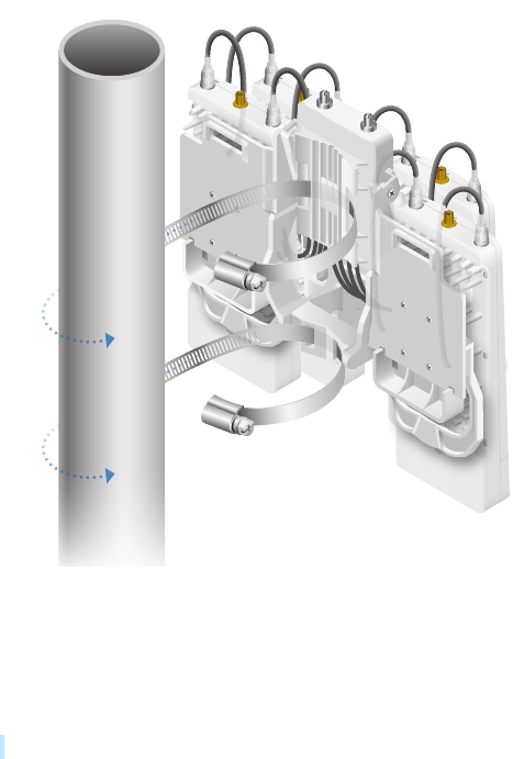
Pole-Mounting
1. Ensure the airFiber NxN Multiplexer is installed vertically
in the 4x4 Radio Bracket.
2. Mount the airFiber NxN assembly to the pole using two
metal straps (not included):
a. Insert a metal strap through each mounting bracket
on the back of the airFiber NxN Multiplexer and 4x4
Radio Bracket.
b. Secure both straps around the pole.
3. Connect the RF cables from the antenna to the
RFconnectors on the airFiber NxN Multiplexer. Connect
+45° to Chain 0 and -45° to Chain 1.
50
Appendix B: AF-5X and airFiber Multiplexer airFiber X User Guide
Ubiquiti Networks, Inc.

51
Appendix C: Listen Before TalkairFiber X User Guide
Ubiquiti Networks, Inc.
Appendix C: Listen Before Talk
Note: This appendix applies to the airFiber AF-3X
radio only.
Introduction
Listen Before Talk (LBT) is a requirement for the 3.6GHz
band in North America and Canada.
Because exclusive licenses for the 3650-3700 MHz band
are not granted within the United States, operators must
take steps to minimize potential interference in this band.
LBT refers to a contention-based protocol (CBP) that
requires a device to check if the transmission channel is in
use (listen) before it can initiate a transmission (talk). FCC
standards that relate to LBT include the following:
• FCC Part 90, Subpart Z requires 3.6 GHz systems to
implement a contention-based protocol to provide
LBT capability. This same requirement has also been
adopted by Industry Canada (IC).
• FCC Part 90, Subpart Z defines two categories of
contention-based protocols, restricted and unrestricted:
- Restricted contention-based protocol This is a
protocol that can detect interference from products
that use a similar contention technology. Systems
using a restricted contention-based protocol operate
in the lower 25 MHz of the frequency band (3650-
3675 MHz).
- Unrestricted contention-based protocol This is a
protocol that can detect interference from products
that use a dissimilar contention technology. Systems
using an unrestricted contention-based protocol use
the full 50MHz (3650-3700 MHz) of the frequency
band.
Unrestricted Protocol Description
The AF-3X Master/Slave system uses dedicated logic for
the LBT protocol, which is embedded into a TDD frame
structure. Energy detection is done at the beginning of
the TX defined by the frame structure of the air interface,
at intervals of 2.0, 2.5, 4.0, or 5.0ms for compatibility
between various other Part 90Z radio devices.
Threshold Detection To Determine
Occupancy
The AF-3X averages the energy detected over a fixed listen
time and compares it to a preconfigured threshold value.
This threshold is configured for values that are within
the linear portion of the radio’s Receive Signal Strength
Indicator (RSSI) dynamic range.
The energy detection threshold is proportional to the
transmitter’s maximum transmit power. For example, if the
transmitter’s EIRP is 23 dBm, then the detection threshold
at the receiver’s input (assuming antenna gain of 0 dBi) is
-73 dBm/MHz.
The detection threshold is adjusted as follows:
DT = -73 dBm/MHz + 10log10(B) + 23 – PT + A
where:
DT = Detection Threshold in dBm
B = Monitored bandwidth in MHz
PT = Maximum transmit power in dBm EIRP
A = Receive antenna gain in dBi
The receive antenna gain A is set equal to the external
antenna gain. The following are set by the operator during
the configuration of the AF-3X radio:
• maximum desired EIRP power PT
• external antenna gain A
• channel bandwidth B
The AF-3X ensures that the sum of the actual conducted
power and the external antenna gain used to calculate PT
does not exceed the regulatory EIRP limit.
The Master/Slave device makes an average measurement
during its Tx and samples the channel every frame
(typically 2.0ms) to accumulate a co-channel signal
measurement. A typical accumulation period is 5µs.
The bandwidth used for all channel occupancy
measurements is the same bandwidth used for system
operation and is configurable for values that range from
3.5MHz to 40MHz.
The detection threshold is configured to scale
automatically based on the in-use modulation level that
the system negotiates. The threshold level is automatically
set by the radio to meet regulatory requirements. All
threshold levels are normalized to a 0 dBi reference level.
The detection system uses the same hardware as the
actual radio lower-level software code and is therefore
operational over the same power range.
The AF-3X point-to-point system employs a proprietary
media access layer (MAC) that utilizes a TDD scheduled
transmission which is synchronized. Both the Master
and Slave employ a threshold detection mechanism
to monitor for other systems running within a selected
channel.
Action Taken When Occupancy is
Determined
Upon detection of occupancy, the Master will cease
transmission. It will continue to monitor the channel to
see if at any point that it becomes available.
Hidden-node problems are avoided by the AF-3X system’s
proprietary media access control (MAC) layer that utilizes
a TDD scheduled transmission (a synchronized framed
transmission). The Slave device cannot transmit until it
is allocated bandwidth from the Master device. If the
Master device detects co-channel signals, the uplink for
the scheduled slot allocation is not granted to the Slave,
preventing the Slave from transmitting. Since permission
to transmit is granted by the Master, there is no hidden
node problem like that experienced by Wi-Fi systems
which employ a contention-based protocol.
52
Appendix C: Listen Before Talk airFiber X User Guide
Ubiquiti Networks, Inc.
Opportunities for Other Transmitters
to Operate
No differences are performed between start-up mode
and operational mode. The Master/Slave device goes
into an energy scanning mode where it is allowed to do
one full cycle of energy detection before it is allowed to
transmit. The scan is a mode where the average energy
is accumulated to compare against the programmed
detection threshold. If the energy detected is less than the
detection threshold, the Master/Slave device is allowed to
make a transmission.
In normal operational mode the system does not allow
any transmission once the threshold has been detected.
Once the energy is no longer present will the system
begin to transmit again.
The Master and Slave uses the energy detected prior to
each transmit frame to control the muting of the transmit
function.
At any load level (no load, typical, or overload), the
system transmits data based on the configuration for the
uplink/downlink ratio The same amount of bandwidth is
reserved for channel detection, so performance remains
unaffected.
If there are two AF-3X systems on a co-channel, they
would share the spectrum as follows:
• Since the system is a synchronized frame-based system,
both systems would operate effectively with each other
because each system can be configured to transmit and
receive at the same point in time. The system uses a
GPS synchronization to time-align the start-of-frame for
all systems deployed.
• If the users configure the number of uplink and
downlink slots and the duty cycle (uplink/downlink
ratio) in an identical manner and each system uses the
same set of uncommitted uplink slots for the detection
sampling interval, then the two systems will co-exist
with no knowledge of the others presence.
• Each system listens prior to transmit and if it detects
activity yields to the other system.
• The system will shut down when the accumulated
energy is above the detection threshold and will
continue to transmit if it is below the detection
threshold. When the co-channel system is clear of the
channel then the target system will go back into regular
operation. Regular operation will consist of a constant
averaging of the energy detected in the uplink slots.

53
Appendix D: Safety NoticesairFiber X User Guide
Ubiquiti Networks, Inc.
Appendix D: Safety Notices
1. Read, follow, and keep these instructions.
2. Heed all warnings.
3. Only use attachments/accessories specified by the
manufacturer.
WARNING: Do not use this product in location that can be
submerged by water.
WARNING: Avoid using this product during an electrical
storm. There may be a remote risk of electric shock from
lightning.
Electrical Safety Information
1. Compliance is required with respect to voltage,
frequency, and current requirements indicated on the
manufacturer’s label. Connection to a different power
source than those specified may result in improper
operation, damage to the equipment or pose a fire
hazard if the limitations are not followed.
2. There are no operator serviceable parts inside this
equipment. Service should be provided only by a
qualified service technician.
3. This equipment is provided with a detachable power
cord which has an integral safety ground wire intended
for connection to a grounded safety outlet.
a. Do not substitute the power cord with one that
is not the provided approved type. Never use an
adapter plug to connect to a 2-wire outlet as this
will defeat the continuity of the grounding wire.
b. The equipment requires the use of the ground wire
as a part of the safety certification, modification or
misuse can provide a shock hazard that can result in
serious injury or death.
c. Contact a qualified electrician or the manufacturer
if there are questions about the installation prior to
connecting the equipment.
d. Protective earthing is provided by Listed AC
adapter. Building installation shall provide
appropriate short-circuit backup protection.
e. Protective bonding must be installed in accordance
with local national wiring rules and regulations.
54
Appendix D: Safety Notices airFiber X User Guide
Ubiquiti Networks, Inc.