Ubiquiti AF2X Digital Point-to-Point Radio User Manual airFiber X User Guide
Ubiquiti Networks, Inc. Digital Point-to-Point Radio airFiber X User Guide
Ubiquiti >
Contents
- 1. user manual Part 1
- 2. user manual Part 2
- 3. user manual Part 3
- 4. user manual Part 4
user manual Part 2
5
Chapter 2: InstallationairFiber® X User Guide
Ubiquiti Networks, Inc.
10. Configure the Wireless Security:
a. Select the AES Key Type, HEX or ASCII.
b. For the Key field:
-HEX Enter 16 bytes (eight, 16-bit HEX values: 0-9,
A-F, or a-f). You can omit zeroes and use colons,
similar to the IPv6 format.
Note: The airFiber Configuration Interface
supports IPv6 formats excluding dotted
quad and “::” (double-colon) notation.
-ASCII Enter a combination of alphanumeric
characters (0-9, A-Z, or a-z).
11. Click Change and then click Apply.
12. In-Band Management is enabled by default, so each
airFiberX radio must have a unique IP Address. (If the
airFiberX radios use the same IP Address, you may lose
access to the airFiberX radios via the DATA ports.) Click
the Network tab.
a. For the Management IP Address option:
-DHCP Keep the default, DHCP, to use DHCP
reservation on your router to assign a unique
IPAddress.
-Static Change the IP Address, Netmask, and other
settings to make them compatible with your
network.
b. Click Change and then click Apply.
Repeat the instructions in the airFiber Configuration
section on your other airFiberX radio. After you have
configured the airFiberX radios, disconnect them and
move them to your installation site.
Hardware Installation
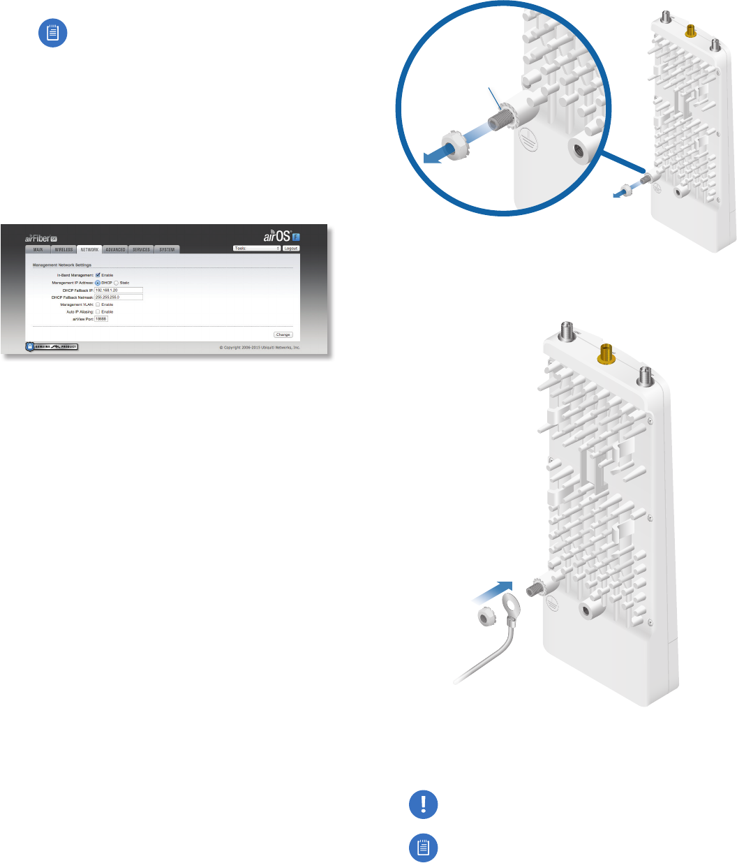
Install a Ground Wire
1. Remove the nut from the Ground Bonding Point located
on the back of the airFiberX radio.
Ground
Bonding
Point
2. Attach a ground wire (min. 10 AWG or 5 mm2) to the
lug and replace the nut to secure the wire.
3. At the installation site, secure the other end of the
ground wire to a grounded mast, pole, tower, or
grounding bar.
WARNING: Failure to properly ground your
airFiberX radio will void your warranty.
Note: The ground wire should be as short as
possible and no longer than one meter in length.
6
Chapter 2: Installation airFiber® X User Guide
Ubiquiti Networks, Inc.
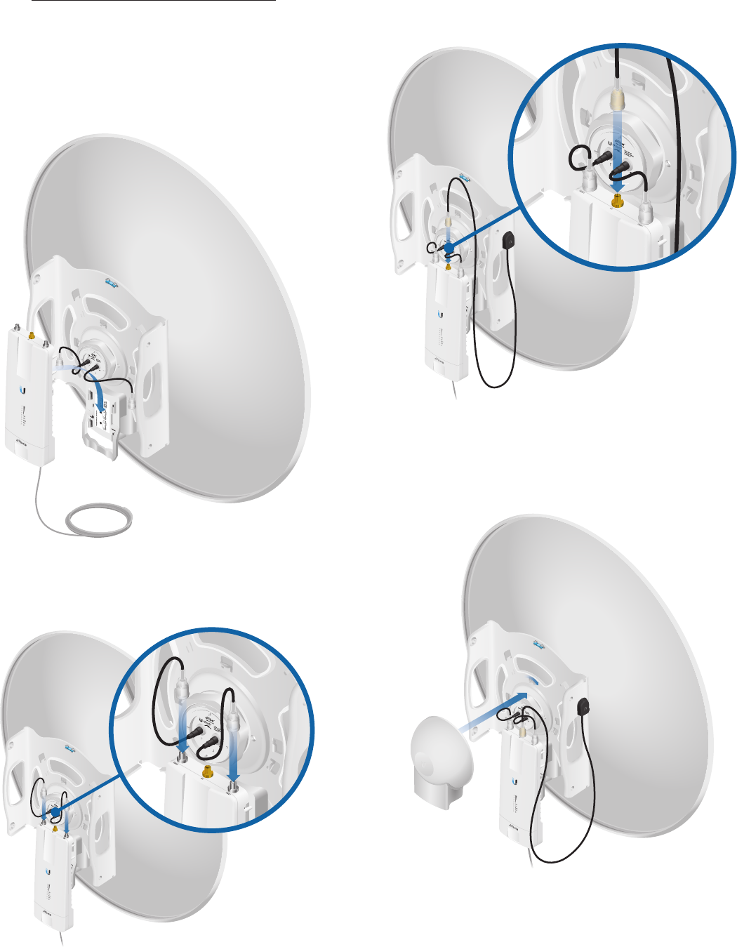
Mount to an Antenna
The airFiberX radio can be mounted to the antenna(s)
listed in “Installation Requirements” on page 3.
The airFiber X Antenna (AF-5G30-S45) is shown in the
following steps:
1. Attach the airFiberX radio to the mounting bracket.
a. Align the mounting tabs on the back of the
airFiberX radio with the mounting bracket.
b. Slide the airFiberX radio down to lock it into place.
2. Attach the RF cables from the antenna feed to the RF
connectors on the airFiberX radio in this combination:
+45°to Chain 0 and -45° to Chain 1.
3. Attach the External GPS Antenna to the RF connector
labeled GPS. Then, place the magnetic External GPS
Antenna on the bracket (this is temporary; you will
mount the External GPS Antenna on the GPS Antenna
Mount at the site).
4. Attach the protective shroud.
a. Align the hash mark on the top of the shroud with
the notch on the dish antenna.
b. Rotate the shroud clockwise until it locks into place.
7
Chapter 2: InstallationairFiber® X User Guide
Ubiquiti Networks, Inc.
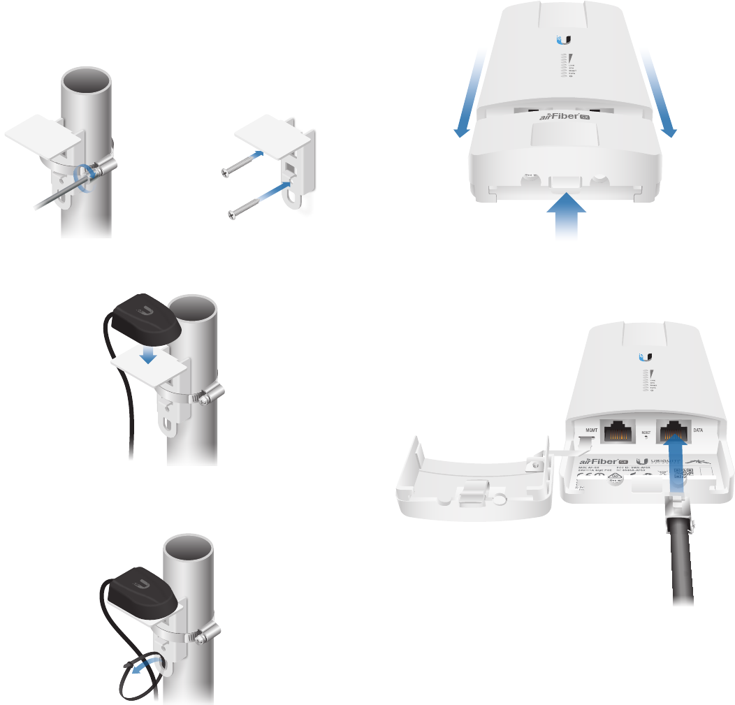
Mount the External GPS Antenna
Locate a mounting point that has a clear view to the
sky, and is above and as far away as possible from the
AirFiberX radio.
1. Attach the GPS Antenna Mount to the pole using the
metal strap, or attach it to a wall using the appropriate
fasteners (notincluded).
2. Place the External GPS Antenna on the mount.
3. Secure the cable of the External GPS Antenna to the
mount with a Cable Tie.
Connecting Power over Ethernet
1. Lift the release latch on the bottom of the airFiberX
radio and slide the Port Cover off.
2. Connect an outdoor, shielded Ethernet cable to the
DATA port.
8
Chapter 2: Installation airFiber® X User Guide
Ubiquiti Networks, Inc.
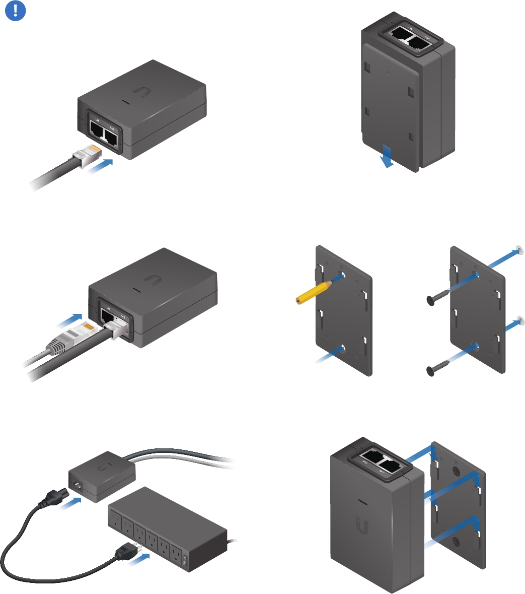
3. Connect the other end of the cable from the DATA port
to the Ethernet port labeled POE on the airFiber PoE
Adapter.
WARNING: Use only the included airFiber PoE
Adapter, Model: GP-H240-100G-4. Failure to do
so can damage the unit and void the product
warranty.
4. Connect an Ethernet cable from your network to the
Ethernet port labeled LAN on the airFiber PoE Adapter.
5. Connect the Power Cord to the power port on the
airFiber PoE Adapter. Connect the other end of the
Power Cord to a power source.
Mount the PoE Adapter (Optional)
1. Remove the Mounting Bracket from the adapter by
sliding the bracket downward.
2. Place the Mounting Bracket at the desired location and
mark the holes for the fasteners. Pre-drill the holes if
necessary, then secure the bracket to the wall using
two fasteners (not included).
3. Attach the airFiber PoE Adapter to the bracket by
aligning the four slots and tabs, and then slide the
adapter downward.
9
Chapter 2: InstallationairFiber® X User Guide
Ubiquiti Networks, Inc.
Surge Protection
For added protection, install two surge suppressors, such
as the Ubiquiti Ethernet Surge Protector, model ETH-SP,
at the end of each link. Install the first surge protector
within one meter of the airFiber DATA port, and install the
second surge protector at the ingress point of the location
housing the wired network equipment.
Ground to Pole, Tower,
or Grounding Block:
Max. 1 m from AF-5X
Max. 1 m
airFiber
PoE Adapter
EdgeRouter™
Power Source
ETH-SP
GPS Antenna
ETH-SP
AF-5X
Mounted on
AF-5G30-S45
Alignment
Tips
• To accurately align the airFiberX radios for best
performance, you MUST align only one end of the link at
a time.
• You may need to use additional hardware to
compensate for issues such as the improper orientation
of a mounting pole or significant elevation differences
between airFiberX radios.
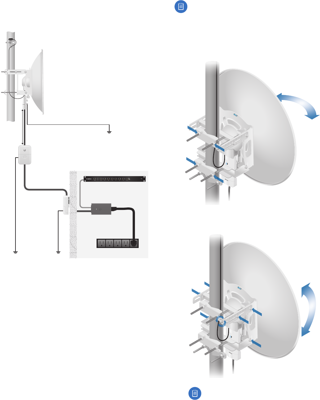
Establishing a Link
Adjust the positions of the Master and the Slave to
establish a link.
Note: The Master must be aimed first at the Slave
because the Slave does not transmit any RF signal
until it detects transmissions from the Master.
1. Master Visually aim the Master at the Slave. To adjust
the Master’s position:
a. Loosen the four pole clamp nuts, and rotate the
airFiber antenna on the pole to align the azimuth.
b. Loosen the six elevation bolts, and use the hex nut
on the elevation rod to adjust the elevation.
Note: Do NOT make simultaneous adjustments
on the Master and Slave.
10
Chapter 2: Installation airFiber® X User Guide
Ubiquiti Networks, Inc.
2. Slave Visually aim the Slave at the Master. To adjust the
Slave’s position:
a. Loosen the four pole clamp nuts, and rotate the
airFiber antenna on the pole to align the azimuth.
b. Loosen the six elevation bolts, and use the hex nut
on the elevation rod to adjust the elevation.
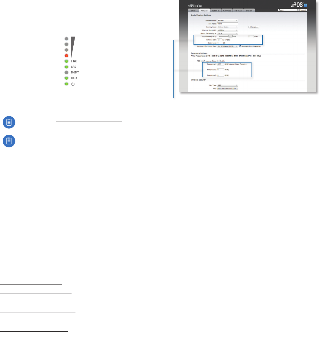
3. Check to see if a link is established. Ensure that the LINK
LED is solidly lit green and the Signal LEDs of the Slave
are displaying signal levels.
4. Slave Aim the Slave at the Master to achieve the
strongest signal level on the Master.
Note: Refer to “Signal LEDs” on page 2 for
details on the signal values.
Note: Maximum signal strength can best be
achieved by iteratively sweeping through both
azimuth and elevation.
5. Master Aim the Master at the Slave to achieve the
strongest signal level on the Slave.
6. Repeat steps 4 and 5 until you achieve an optimal link,
with all four Signal LEDs solidly lit. This ensures the best
possible data rate between the airFiberX radios.
7. Lock the alignment on both airFiber antennas by
tightening all the nuts and bolts.
8. Observe the Signal LEDs of each airFiberX radio
to ensure that the values remain constant while
tightening the nuts and bolts. If any LED value changes
during the locking process, loosen the nuts and bolts,
finalize the alignment of each airFiber antenna again,
and retighten the nuts and bolts.
Refer to the following chapters of this User Guide for
details on the airFiber Configuration Interface:
• “Main Tab” on page 13
• “Wireless Tab” on page 17
• “Network Tab” on page 20
• “Advanced Tab” on page 22
• “Services Tab” on page 25
• “System Tab” on page 29
• “Tools” on page 32
Installer Compliance Responsibility
Devices must be professionally installed and it is the
professional installer’s responsibility to make sure the
device is operated within local country regulatory
requirements.
The Output Power, Antenna Gain, Cable Loss, and Frequency
fields are provided to the professional installer to assist in
meeting regulatory requirements.
11
Chapter 3: NavigationairFiber® X User Guide
Ubiquiti Networks, Inc.
Chapter 3: Navigation
The airFiber Configuration Interface is an advanced
operating system capable of powerful wireless and
routing features, built upon a simple and intuitive user
interface foundation.
The airFiberX radio uses the airFiber Configuration
Interface for easy configuration and management via a
web browser.
There are two ways to access the airFiber Configuration
Interface:
• Management Port Enabled by default. Use a direct
connection to the Management port for out-of-band
management.
• In-Band Management Enabled by default. In-band
management is available through the local Data port
or the Data port at the other end of the link. You can
disable it on the Network tab. (See “Management
Network Settings” on page 20 for more details.)
Accessing the airFiber Configuration
Interface
Connect to the airFiber Configuration Interface.
1. Make sure that your host machine is connected to the
LAN that is connected to the Management port on
theairFiberX radio.
2. Configure the Ethernet adapter on your host system
with a static IP address on the 192.168.1.x subnet (for
example, 192.168.1.100).
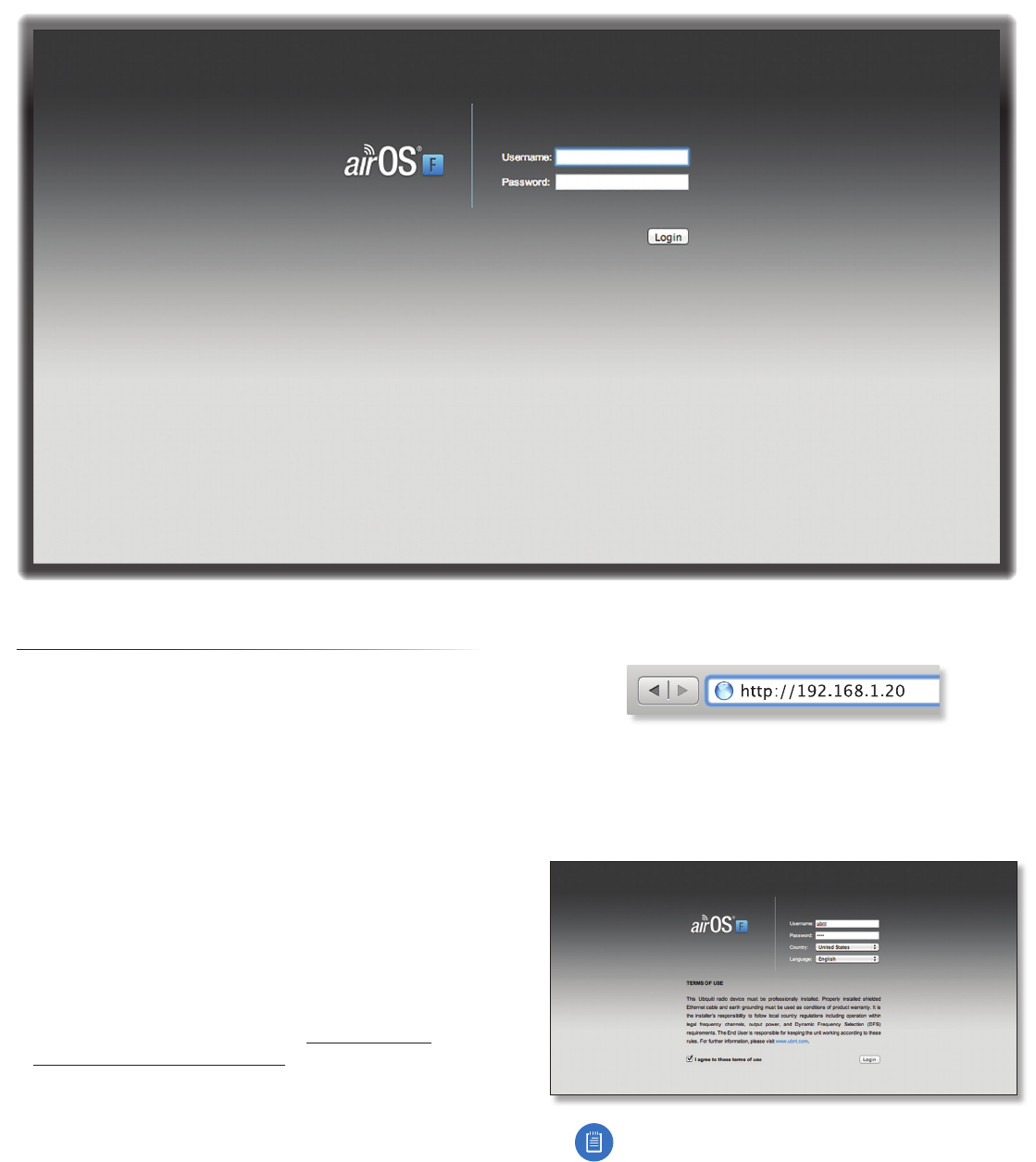
3. Launch your web browser. Type http://192.168.1.20 in
the address field and press enter (PC) or return (Mac).
4. Upon initial login, the Terms of Use appear on the login
screen. Enter ubnt in the Username and Password fields,
and select the appropriate choices from the Country
and Language drop-down lists. Check the box next to
Iagree to these terms of use, and click Login.
Note: U.S. product versions are locked to the U.S.
Country Code to ensure compliance with FCC
regulations.
5. The airFiber Configuration Interface will appear,
allowing you to customize your settings as needed.
12
Chapter 3: Navigation airFiber® X User Guide
Ubiquiti Networks, Inc.
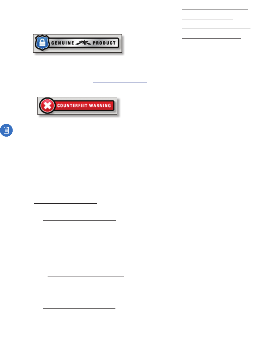
Product Verification
The airFiber Configuration Interface will verify whether a
product is genuine or counterfeit.
For a genuine airFiber airFiberX radio, the airFiber
Configuration Interface will display a Genuine Product
logo in the lower left corner of the screen.
For any product that is not an official Ubiquiti product, the
airFiber Configuration Interface will display a counterfeit
warning. Please contact Ubiquiti at support@ubnt.com
regarding this product.
Note: For product models introduced prior to 2012,
the airFiber Configuration Interface will NOT display
any logo in the lower left corner of the screen.
Interface Tabs
The airFiber Configuration Interface contains six main
tabs, each of which provides a web-based management
page to configure a specific aspect of the airFiberX radio.
This User Guide covers each tab with a chapter. For details
on a specific tab, refer to the appropriate chapter.
• Main The “Main Tab” on page 13 displays device
status, statistics, and network monitoring links.
• Wireless The “Wireless Tab” on page 17 configures
basic wireless settings, including the wireless mode, link
name, frequency, output power, speed, and wireless
security.
• Network The “Network Tab” on page 20 configures
the management network settings, Internet Protocol (IP)
settings, management VLAN, and automatic IP aliasing.
• Advanced The “Advanced Tab” on page 22
provides more precise wireless interface controls,
including advanced wireless settings and advanced
Ethernet settings.
• Services The “Services Tab” on page 25 configures
system management services: Ping Watchdog, Simple
Network Management Protocol (SNMP), servers (web,
SSH, telnet), Network Time Protocol (NTP) client,
Dynamic Domain Name System (DDNS) client, system
log, and device discovery.
• System The “System Tab” on page 29 controls
system maintenance routines, administrator account
management, location management, device
customization, firmware update, and configuration
backup. You can also change the language of the web
management interface.
Each page also contains network administration and
monitoring tools:
• “Align Antenna” on page 32
• “Discovery” on page 33
• “Ping” on page 33
• “Traceroute” on page 33
• “airView” on page 33