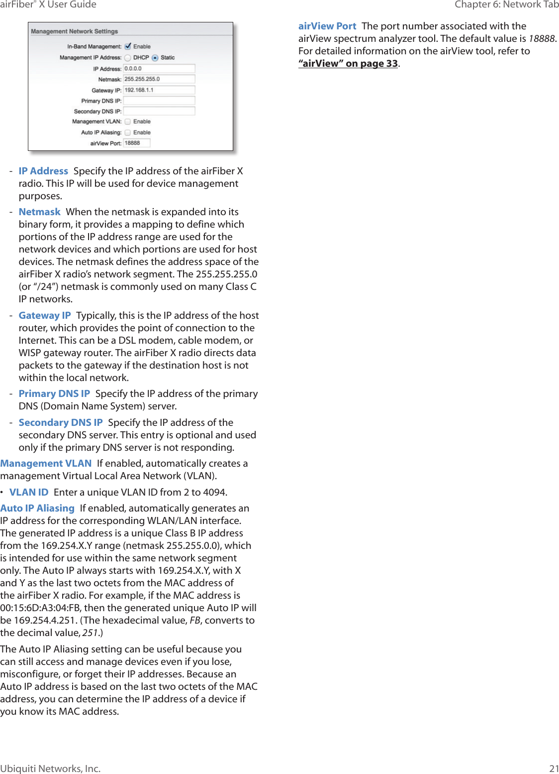
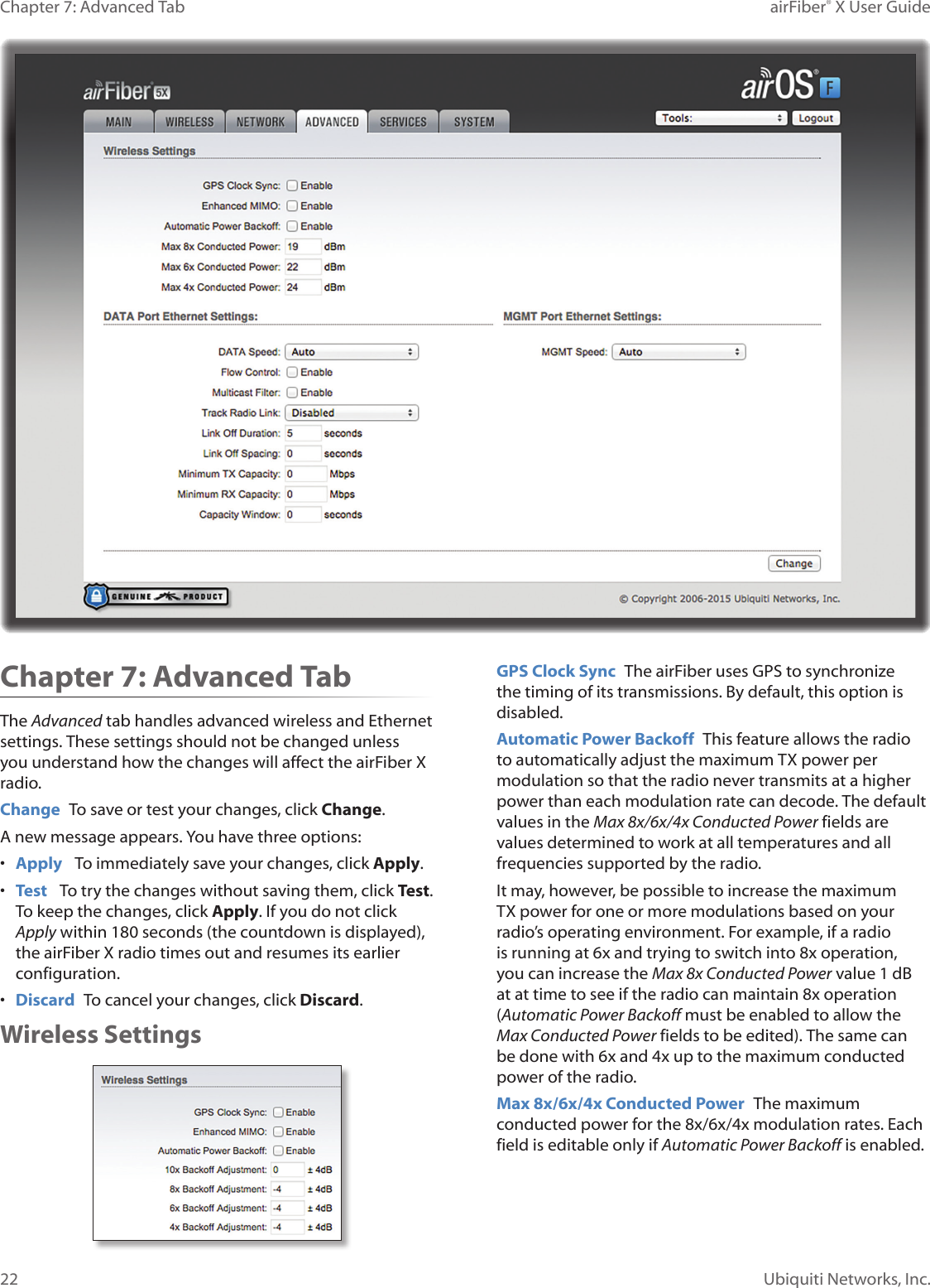
Ubiquiti AF2X Digital Point-to-Point Radio User Manual airFiber X User Guide
Ubiquiti Networks, Inc. Digital Point-to-Point Radio airFiber X User Guide
Ubiquiti >
Contents
- 1. user manual Part 1
- 2. user manual Part 2
- 3. user manual Part 3
- 4. user manual Part 4
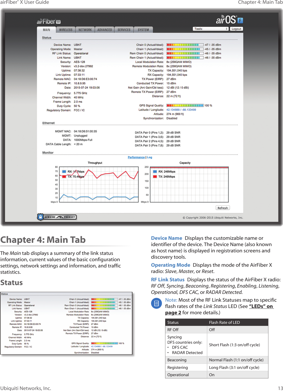
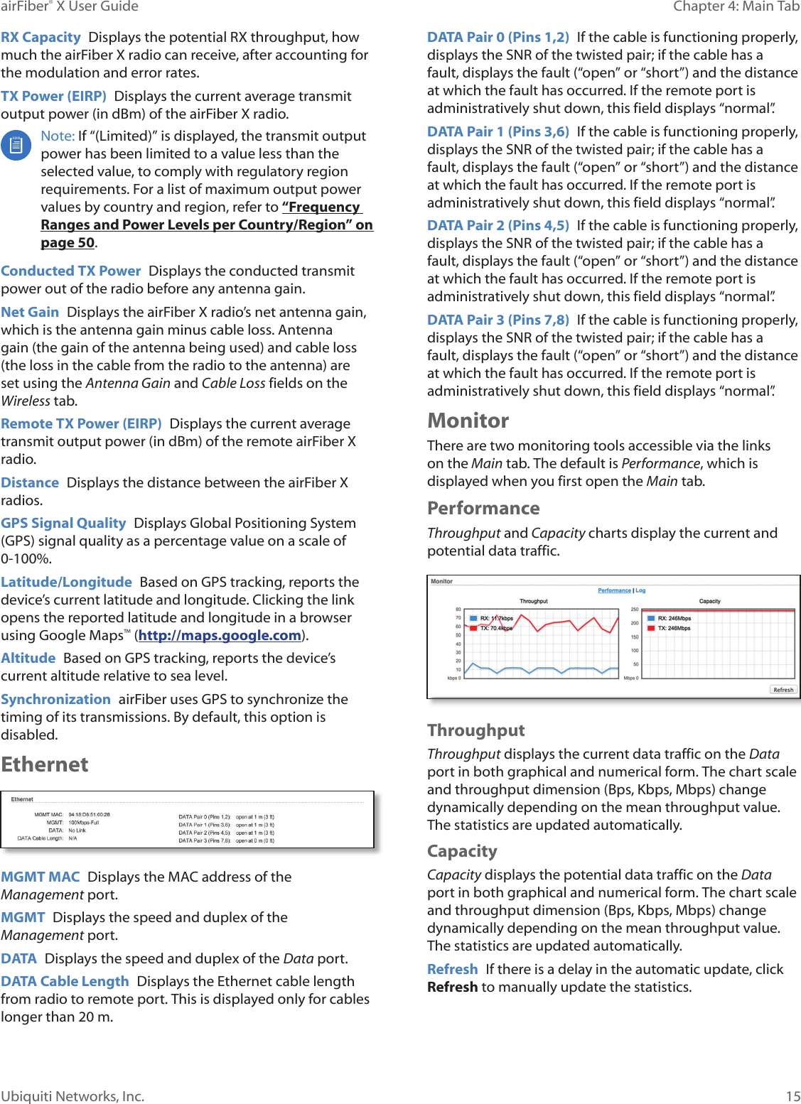
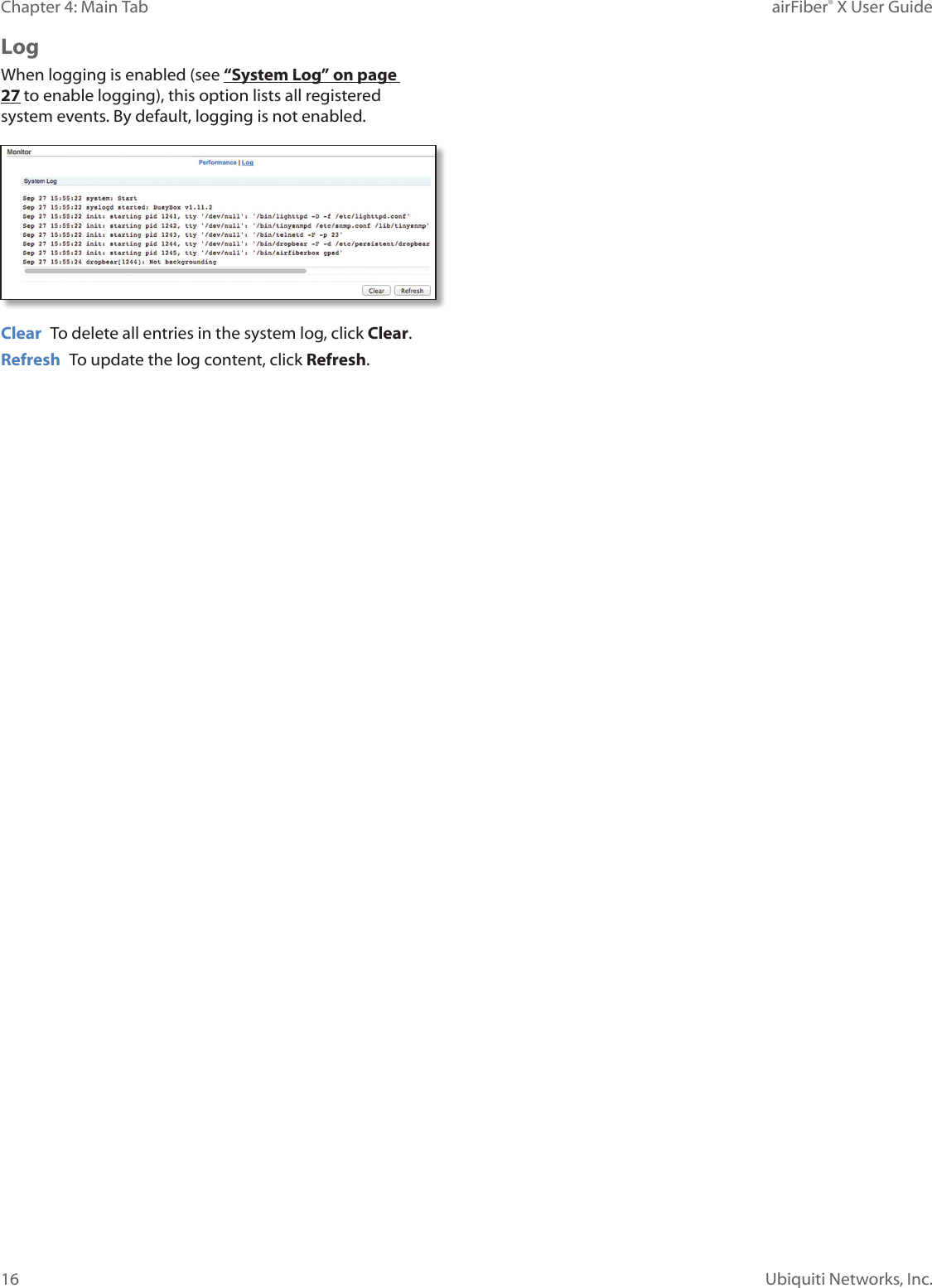
user manual Part 3