Ubiquiti AF2X Digital Point-to-Point Radio User Manual airFiber X User Guide
Ubiquiti Networks, Inc. Digital Point-to-Point Radio airFiber X User Guide
Ubiquiti >
Contents
- 1. user manual Part 1
- 2. user manual Part 2
- 3. user manual Part 3
- 4. user manual Part 4
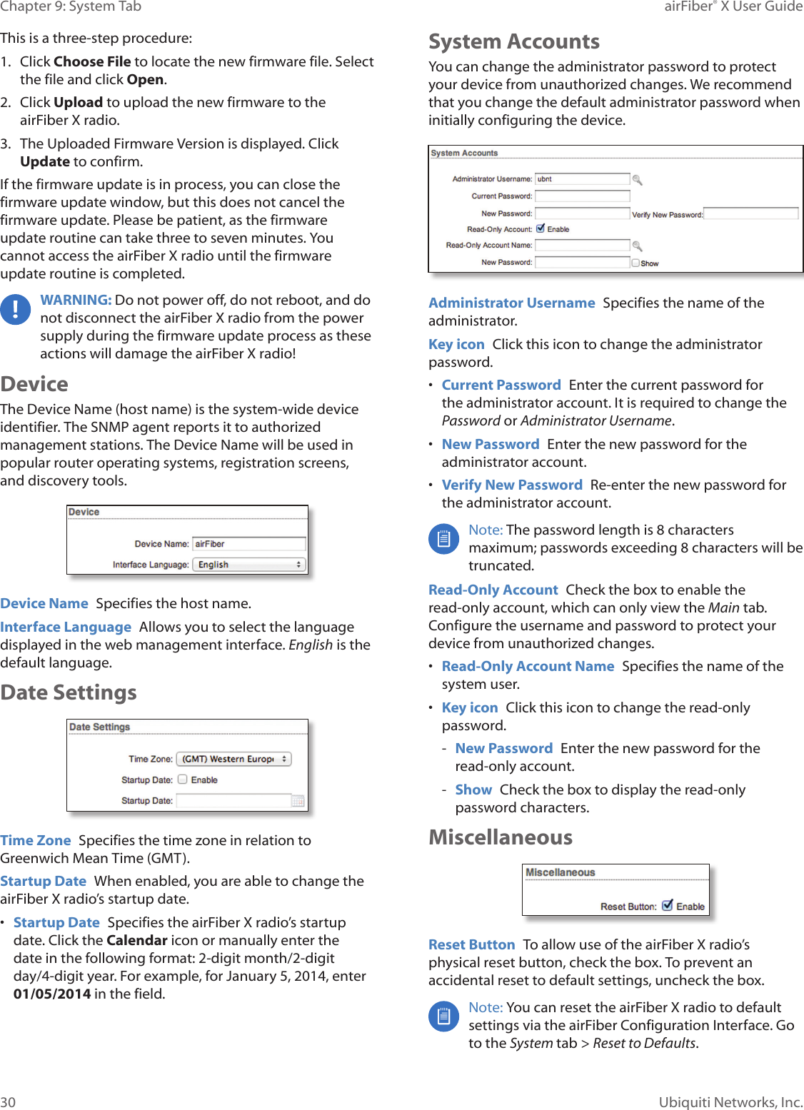
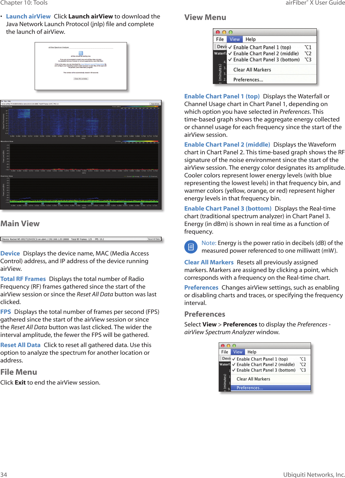
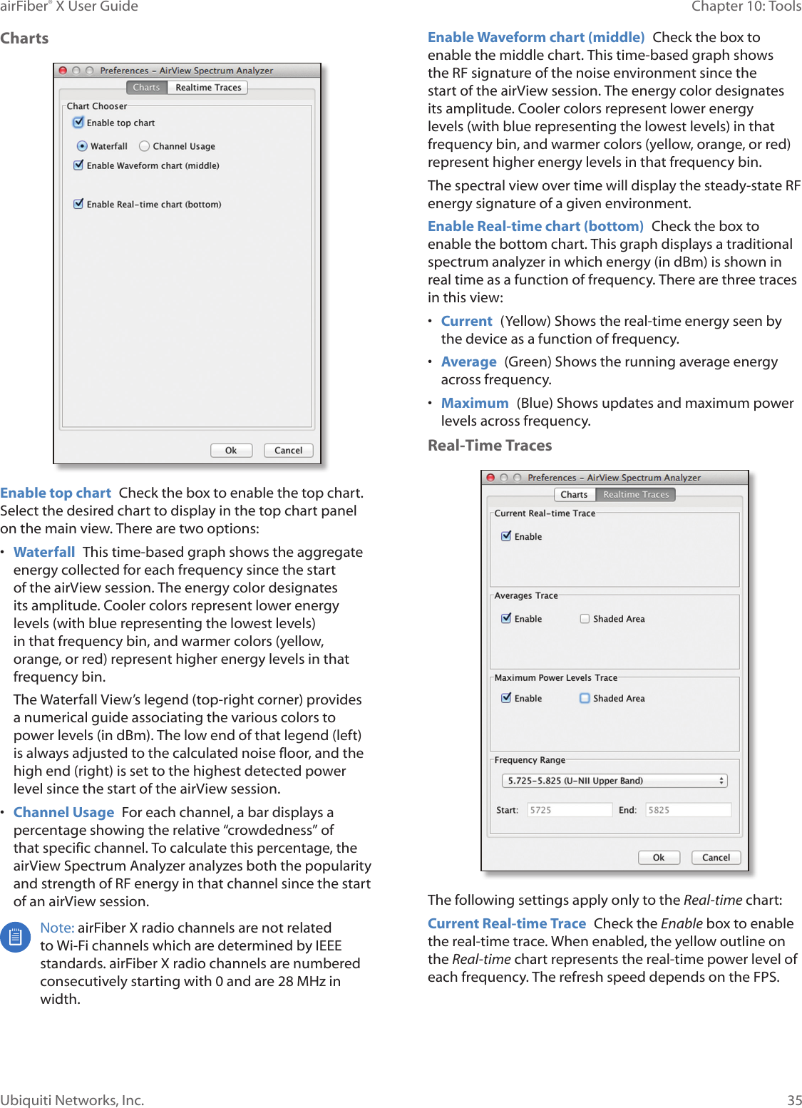
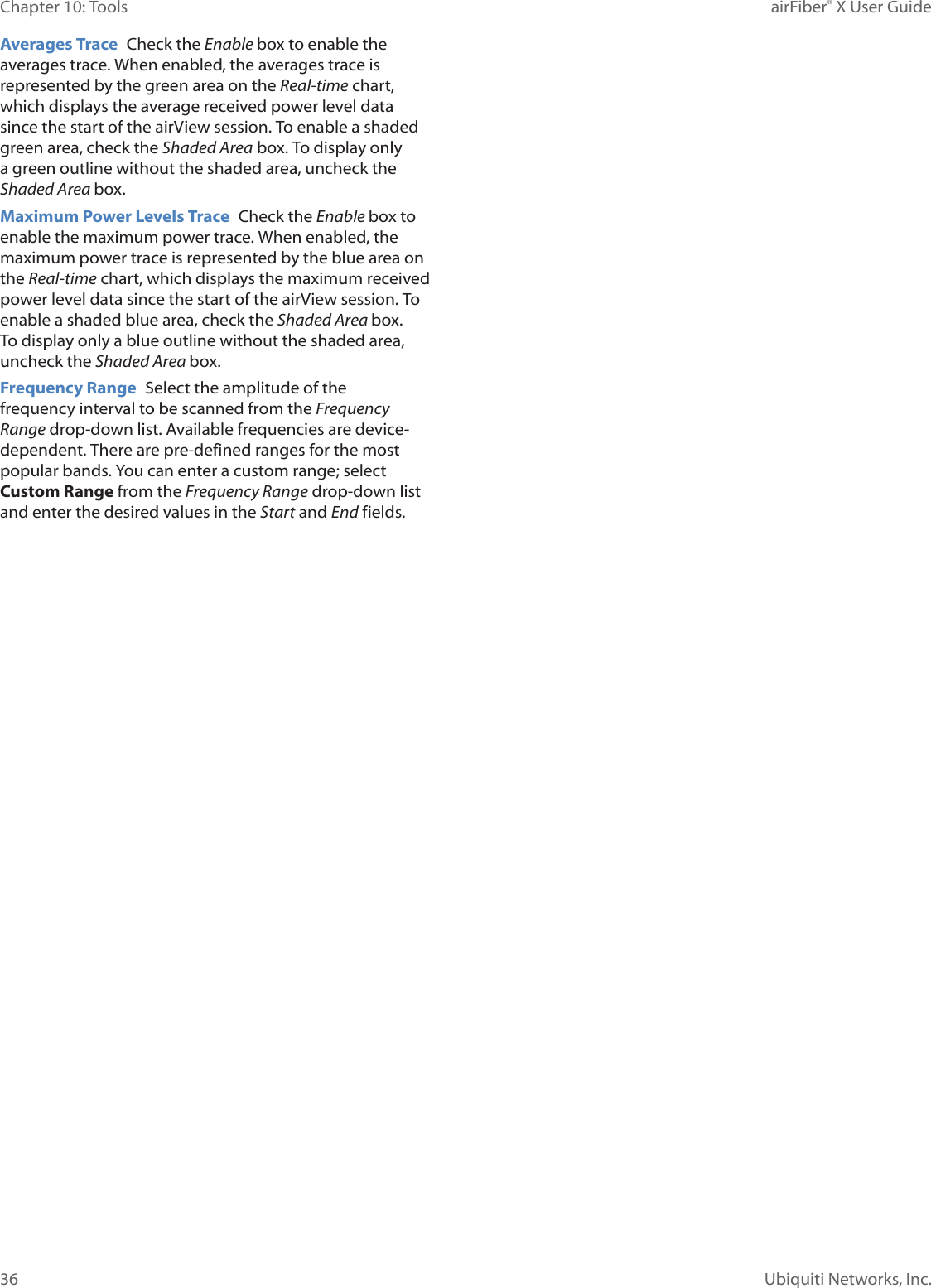
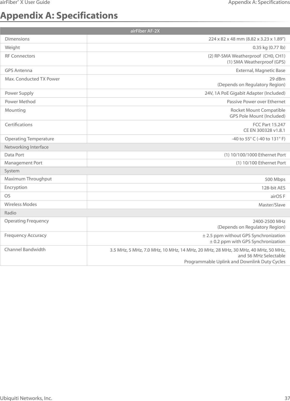
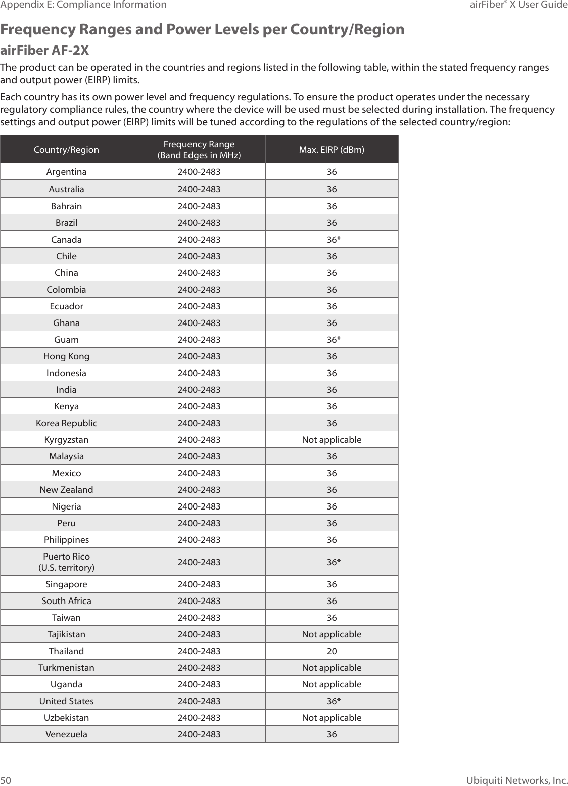
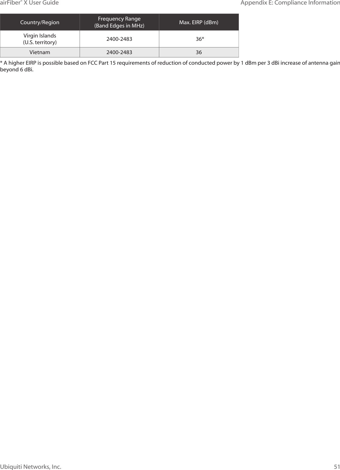
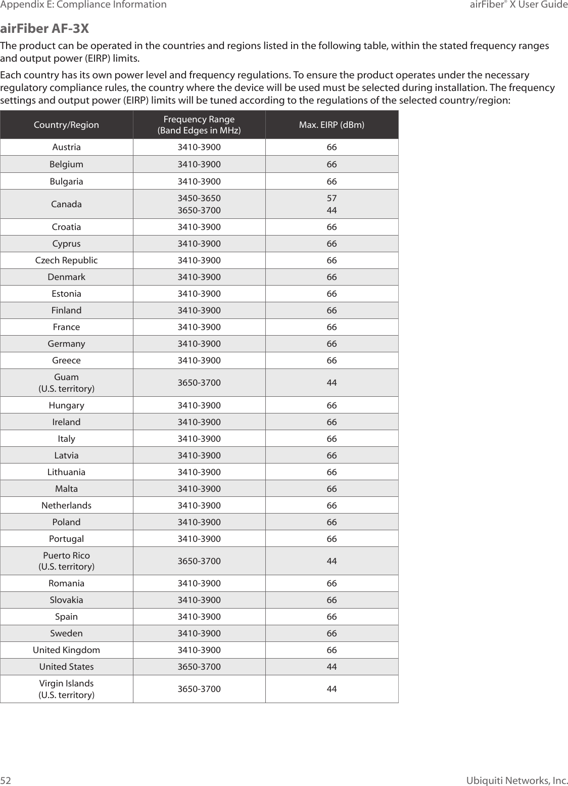
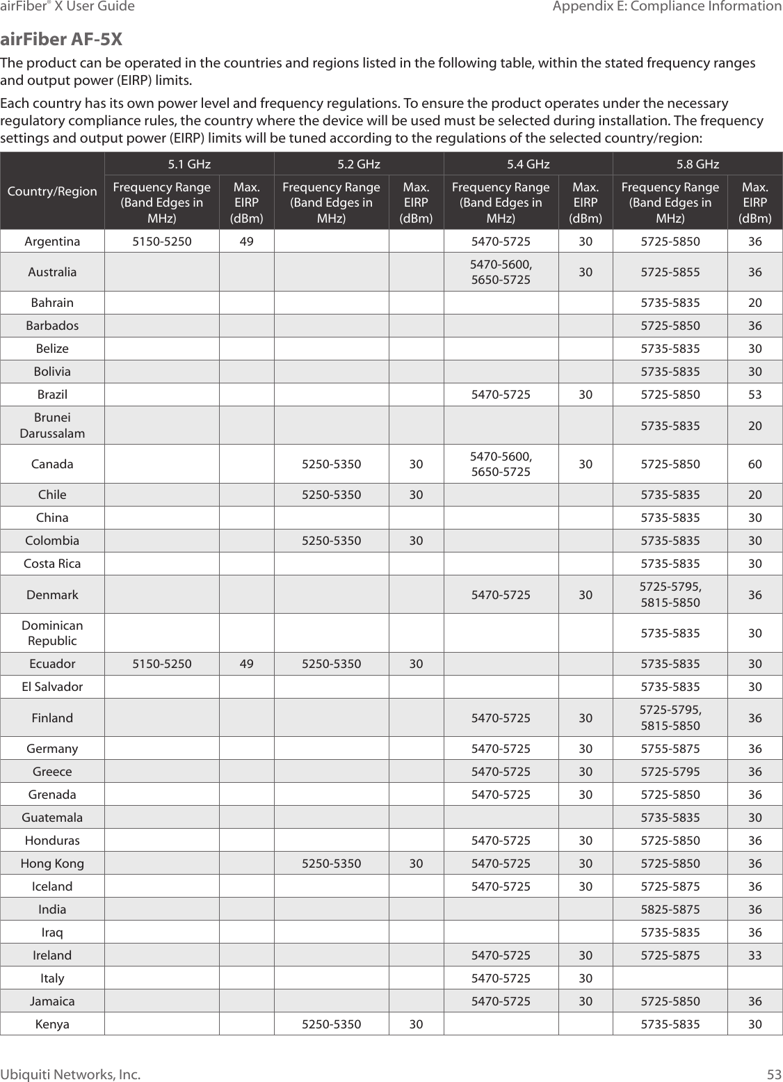
user manual Part 4
![57Appendix F: Declaration of ConformityairFiber® X User GuideUbiquiti Networks, Inc.Appendix F: Declaration of ConformityČesky [Czech]UBIQUITI NETWORKS tímto prohlašuje, že toto UBIQUITI NETWORKS zařízení, je ve shod se základními požadavky a dalšími příslušnými ustanoveními směrnice 1999/5/ES.Dansk [Danish]Hermed, UBIQUITI NETWORKS, erklærer at denne UBIQUITI NETWORKS enhed, er i overensstemmelse med de væsentlige krav og øvrige relevante krav i direktiv 1999/5/EF.Nederlands [Dutch]Hierbij verklaart UBIQUITI NETWORKS, dat deze UBIQUITI NETWORKS apparaat, in overeenstemming is met de essentiële eisen en de andere relevante bepalingen van richtlijn 1999/5/EC.EnglishHereby, UBIQUITI NETWORKS, declares that this UBIQUITI NETWORKS device, is in compliance with the essential requirements and other relevant provisions of Directive 1999/5/EC.Eesti [Estonian]Käesolevaga UBIQUITI NETWORKS kinnitab, et antud UBIQUITI NETWORKS seade, on vastavus olulistele nõuetele ja teistele asjakohastele sätetele direktiivi 1999/5/EÜ.Suomi [Finnish]Täten UBIQUITI NETWORKS vakuuttaa, että tämä UBIQUITI NETWORKS laite, on yhdenmukainen olennaisten vaatimusten ja muiden sitä koskevien direktiivin 1999/5/EY.Français [French]Par la présente UBIQUITI NETWORKS déclare que l’appareil UBIQUITI NETWORKS, est conforme aux exigences essentielles et aux autres dispositions pertinentes de la directive 1999/5/CE.Deutsch [German]Hiermit erklärt UBIQUITI NETWORKS, dass sich dieses UBIQUITI NETWORKS Gerät, in Übereinstimmung mit den grundlegenden Anforderungen und den anderen relevanten Vorschriften der Richtlinie 1999/5/EG befindet.Ελληνική [Greek]Δια του παρόντος, UBIQUITI NETWORKS, δηλώνει ότι αυτή η συσκευή UBIQUITI NETWORKS, είναι σε συμμόρφωση με τις βασικές απαιτήσεις και τις λοιπές σχετικές διατάξεις της οδηγίας 1995/5/ΕΚ.Magyar [Hungarian]Ezennel UBIQUITI NETWORKS kijelenti, hogy ez a UBIQUITI NETWORKS készülék megfelel az alapvető követelményeknek és más vonatkozó 1999/5/EK irányelv rendelkezéseit.Íslenska [Icelandic]Hér, UBIQUITI NETWORKS, því yfir að þetta UBIQUITI NETWORKS tæki er í samræmi við grunnkröfur og önnur viðeigandi ákvæði tilskipun 1999/5/EC.Italiano [Italian]Con la presente, UBIQUITI NETWORKS, dichiara che questo dispositivo UBIQUITI NETWORKS, è conforme ai requisiti essenziali ed alle altre disposizioni pertinenti della direttiva 1999/5/CE.Latviski [Latvian]Ar šo, UBIQUITI NETWORKS, deklarē, ka UBIQUITI NETWORKS ierīce, ir saskaņā ar būtiskajām prasībām un citiem attiecīgiem noteikumiem Direktīvā 1999/5/EK.Lietuviškai [Lithuanian]UBIQUITI NETWORKS deklaruoja, kad šis UBIQUITI NETWORKS įrenginys atitinka esminius reikalavimus ir kitas 1999/5/EB Direktyvos nuostatas.Malti [Maltese]Hawnhekk, UBIQUITI NETWORKS, tiddikjara li dan il-mezz UBIQUITI NETWORKS huwa konformi mar-rekwiżiti essenzjali u dispożizzjonijiet rilevanti oħrajn ta ‘Direttiva 1999/5/EC.Norsk [Norwegian]Herved UBIQUITI NETWORKS, erklærer at denne UBIQUITI NETWORKS enheten, er i samsvar med de grunnleggende kravene og andre relevante bestemmelser i direktiv 1999/5/EF.Slovensky [Slovak]Týmto UBIQUITI NETWORKS, prehlasuje, že toto UBIQUITI NETWORKS zariadenie, je v súlade so základnými požiadavkami a ďalšími relevantnými ustanoveniami smernice 1999/5/ES.Svenska [Swedish]Härmed UBIQUITI NETWORKS, intygar att denna UBIQUITI NETWORKS enhet är i överensstämmelse med de väsentliga egenskapskrav och övriga relevanta bestämmelser som framgår av direktiv 1999/5/EG.Español [Spanish]Por medio de la presente UBIQUITI NETWORKS declara que este dispositivo UBIQUITI NETWORKS, cumple con los requisitos esenciales y cualesquiera otras disposiciones aplicables o exigibles de la Directiva 1999/5/CE.Polski [Polish]Niniejszym, Ubiquiti Networks, oświadcza, że urządzenie UBIQUITI NETWORKS, jest zgodny z zasadniczymi wymaganiami oraz pozostałymi stosownymi postanowieniami Dyrektywy 1999/5/EC.Português [Portuguese]UBIQUITI NETWORKS declara que este dispositivo UBIQUITI NETWORKS, está conforme com os requisitos essenciais e outras disposições da Directiva 1999/5/CE.Română [Romanian]Prin prezenta, UBIQUITI NETWORKS declară că acest dispozitiv UBIQUITI NETWORKS este în conformitate cu cerințele esențiale și alte prevederi relevante ale Directivei 1999/5/CE.](https://usermanual.wiki/Ubiquiti/AF2X.user-manual-Part-4/User-Guide-2713924-Page-35.png)