Ubiquiti XR5 2.4GHz Mini PCI module User Manual
Ubiquiti Networks, Inc. 2.4GHz Mini PCI module
UserManual.wiki
>
Ubiquiti
>
XR5 User Manual
>
User Manual
Contents
1.
OEM Guide
2.
User Manual
3.
Users Manual
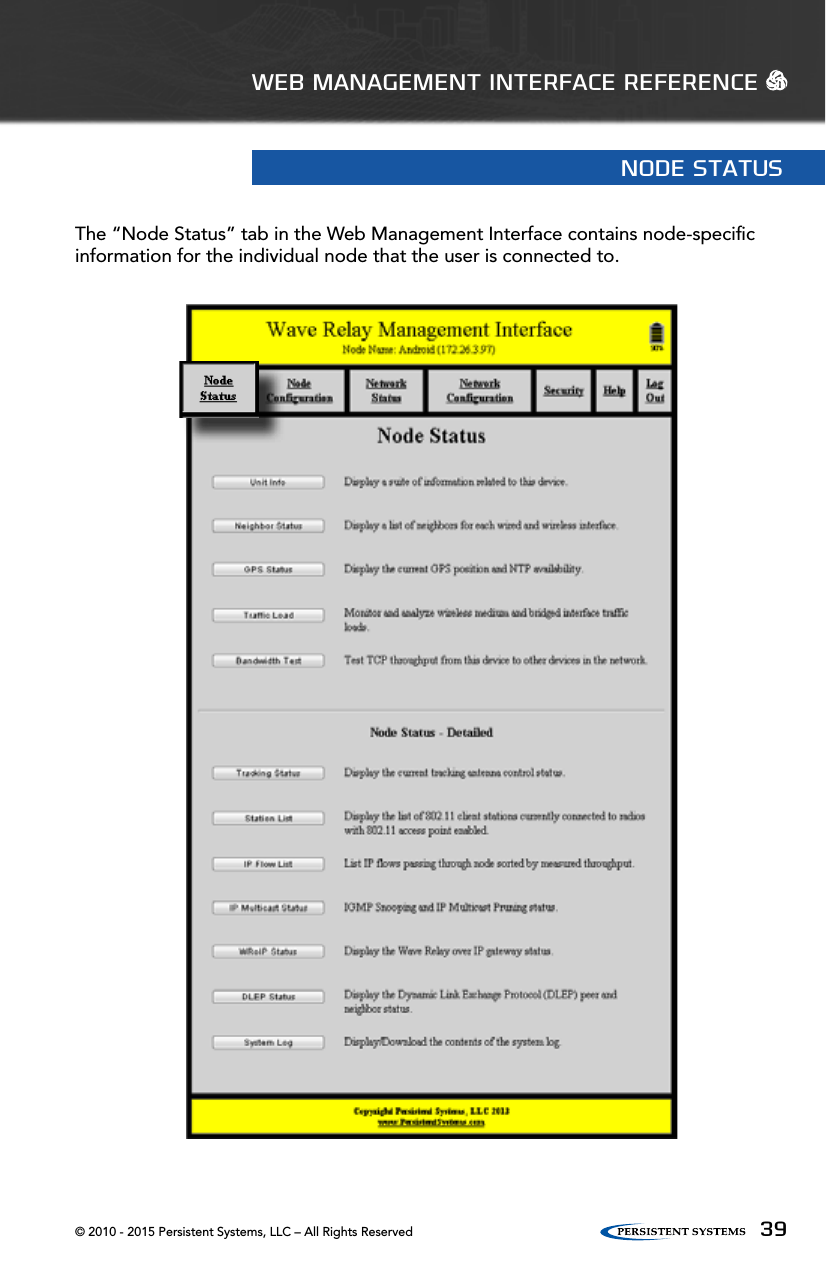
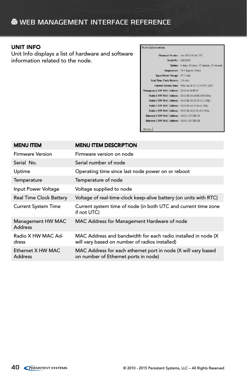
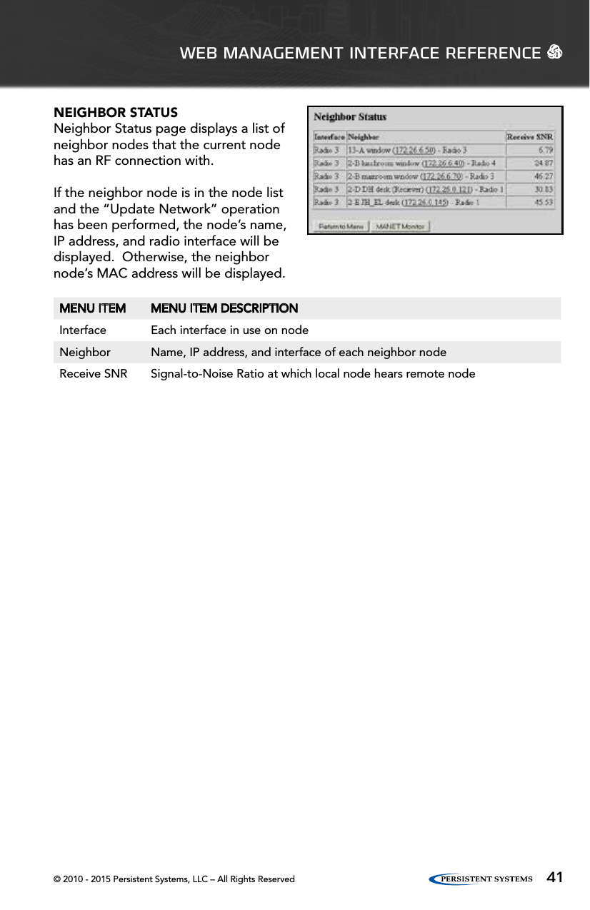
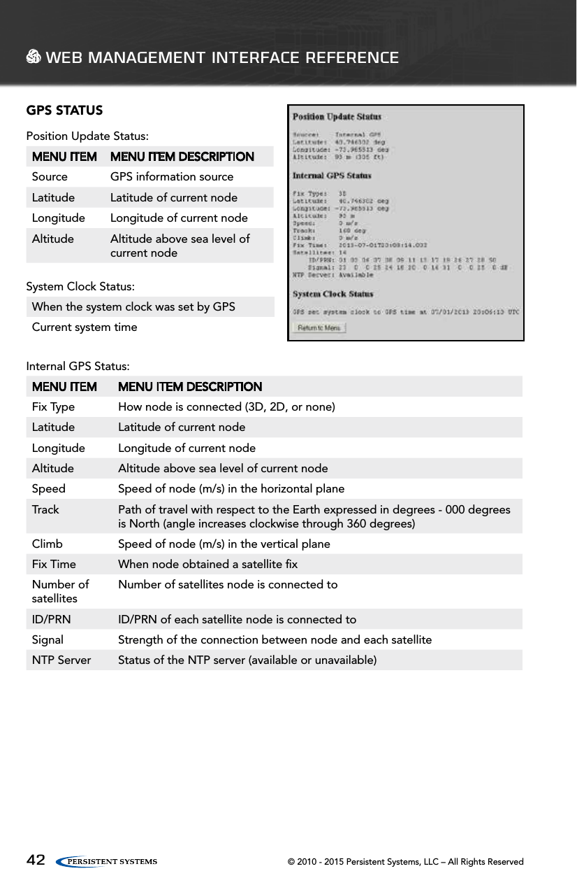
User Manual
Navigation menu
Upload a User Manual
Namespaces
Wiki Guide
HTML
PDF
Info
Views
User Manual
Discussion / Help
Navigation


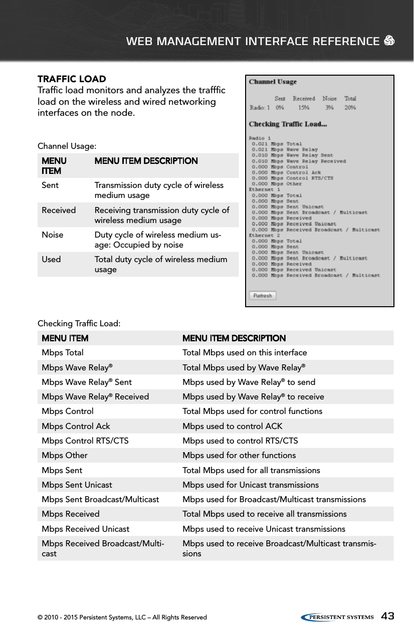
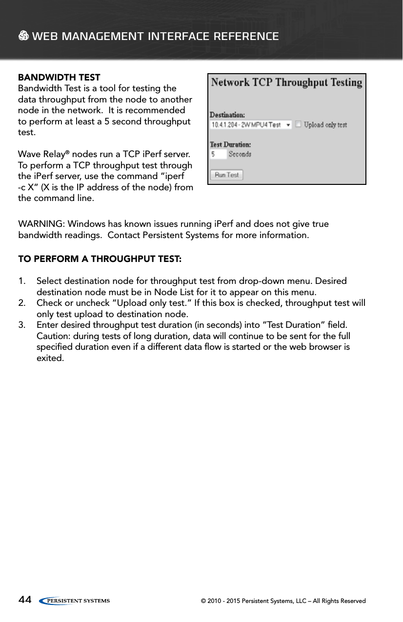
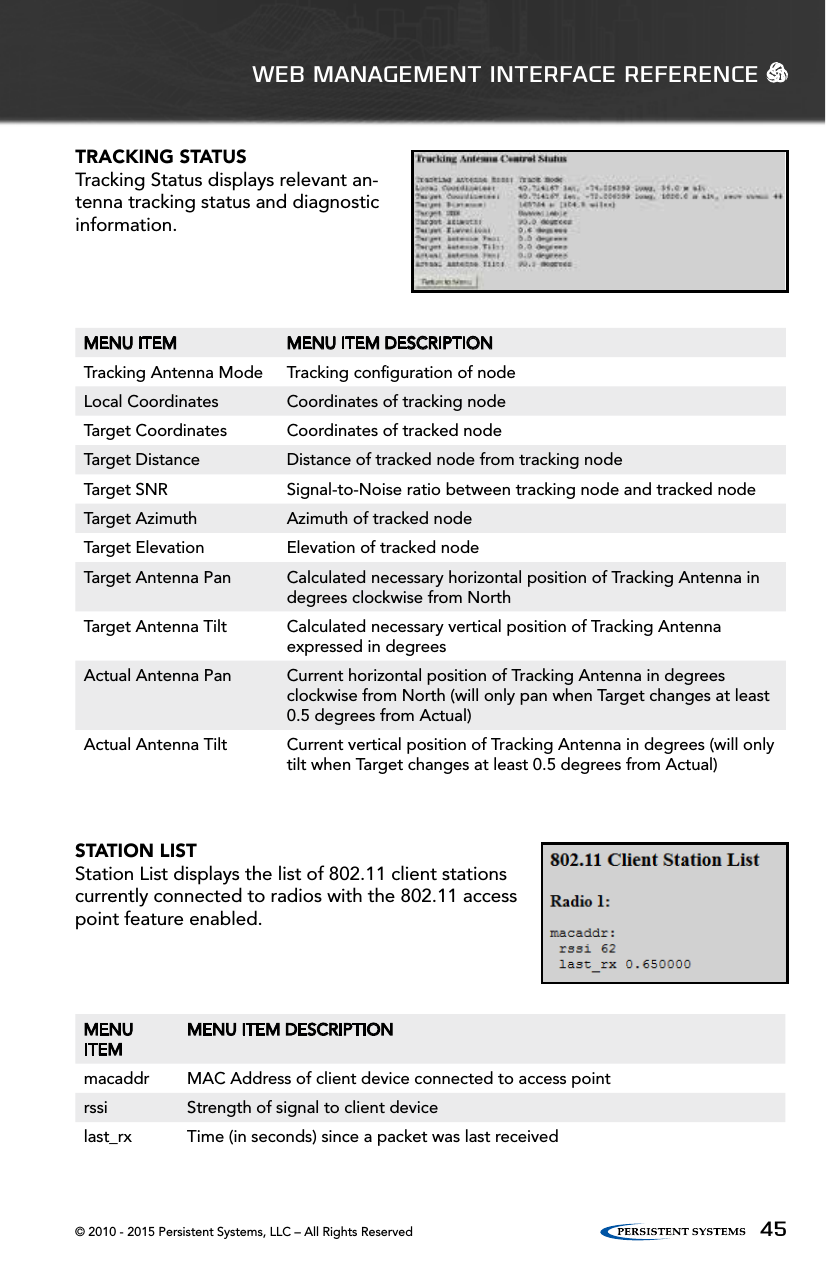
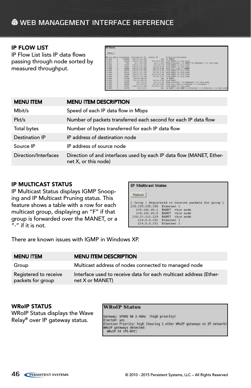
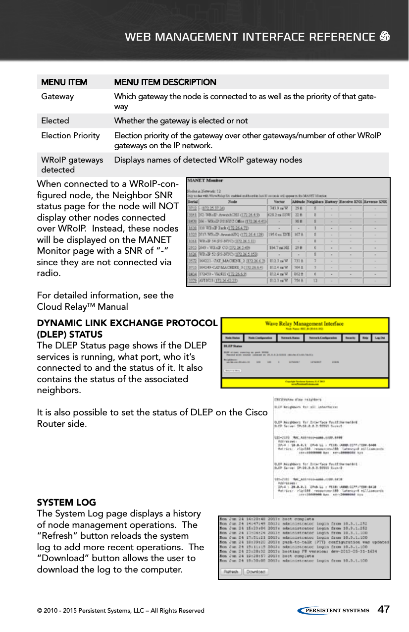
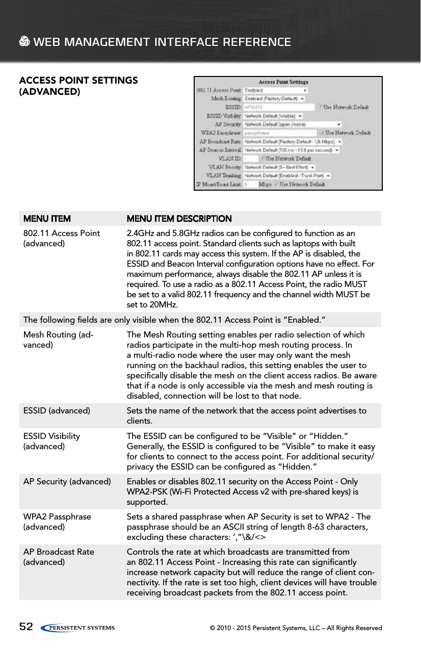
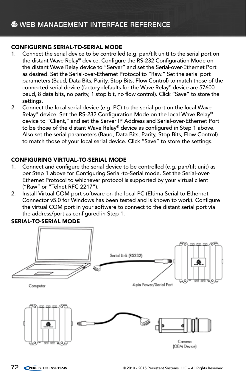
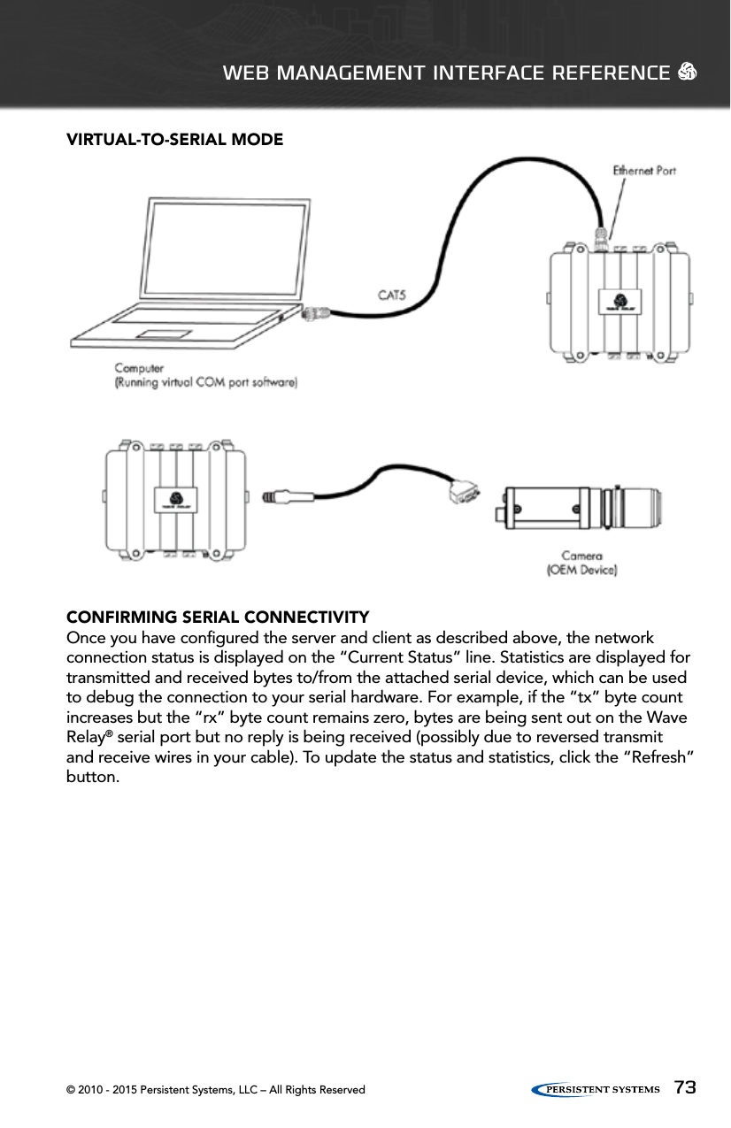
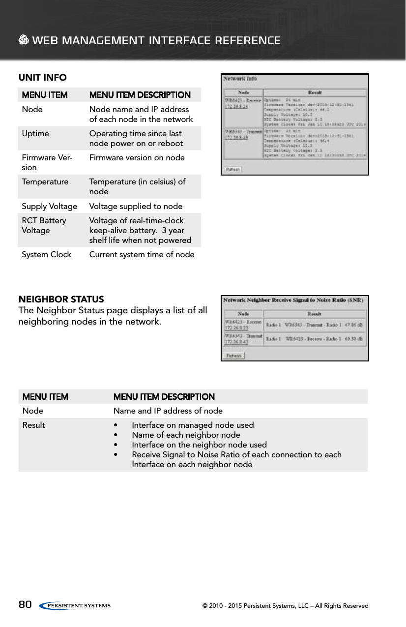
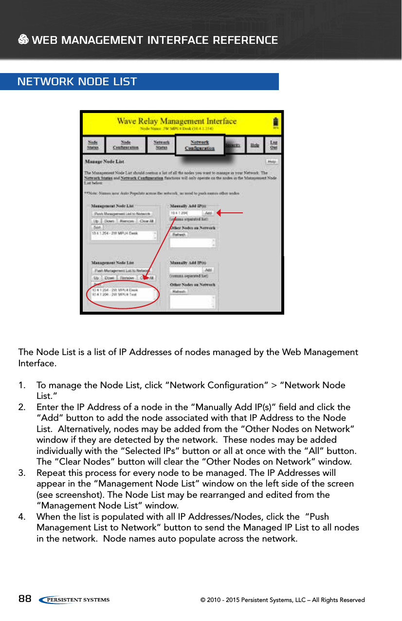
![© 2010 - 2015 Persistent Systems, LLC – All Rights Reserved 23For your computer to be able to communicate with the Wave Relay®, it must have an IP address that is in the same IP subnet mask as the Wave Relay®’s IP address. A subnet mask of 255.255.255.0 means that the computer can communicate with another device that has an IP address matching the first three numbers of its own IP address. No Default Gateway or DNS server configuration is required; however they can be configured if necessary. Most computers are capable of having more then one IP address configured on a single Ethernet adapter. It is recommended that you add all three addresses to your wired Ethernet adapter so that you can easily manage your network.CONFIGURING YOUR COMPUTER’S IP ADDRESSWINDOWS:Start > Network (Right Click) > Properties Change Adapter Settings (Windows Vista / 7 only) Local Area Connection (Right Click) > Properties Select Internet Protocol Version 4 (TCP/IPv4) Click Properties Select Use the following IP AddressClick Advanced…Click Add…Enter IP Address and Subnet maskClick Add and repeat for all IP Addresses LINUX:[sudo] ifconfig eth0 10.4.1.10/24 [sudo] ip addr add 10.3.1.10/24 dev eth0 [sudo] ip addr add 10.3.2.10/24 dev eth0WEB MANAGEMENT OVERVIEW](https://usermanual.wiki/Ubiquiti/XR5.User-Manual/User-Guide-2609898-Page-23.png)


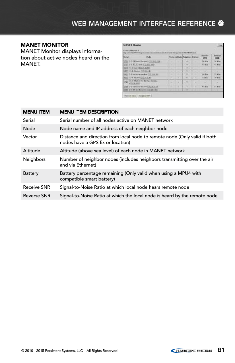
![© 2010 - 2015 Persistent Systems, LLC – All Rights Reserved96 WEB MANAGEMENT INTERFACE REFERENCEMENU ITEM MENU ITEM DESCRIPTIONSend Position Enables or disables transmission of CoT packets to serverServer IP Defines the IP address of the CoT server - This IP address can be a unicast or multicast addressServer Port Defines the UDP port of the CoT serverType Defines the contents of the CoT “type” attributeCURSOR ON TARGET (COT) SETTINGS(ADVANCED)This feature enables transmission of local positioning information to a CoT server on the network. This feature is not available on all firmware versions.SIMPLE SA PACKET GENERATOR (SSPG) (ADVANCED)These settings exist for backwards compatability with an outdated protocol. See earlier versions of the manual for more information.Visualization Server (advanced)Defines the IP address to which nodes will send their visualization updates (may be either a multicast address [224.0.0.0,239.255.255.255] or the unicast address of a device running the visualization server.) - The factory default is a multicast address. When using multicast, each node sends visualization updates to the entire connected network. All nodes run a visualization server and receive updates from all other connected nodes. When using unicast, each node sends visualization updates to the selected address only. If the unicast address is the management IP address of a node, that node will run a visualization server to receive the updates. Visualization updates are sent from the management IP address, so the selected address must be reachable by all nodes with visualization enabled; it should be either in the same subnet or reachable through the default gateway. Multicast operation allows the most robust visualization for mobile networks because it provides true distributed operation with partitions and merges. Unicast operation requires all visualization users to be able to contact the selected server, but offers reduced network overhead for larger static networks.](https://usermanual.wiki/Ubiquiti/XR5.User-Manual/User-Guide-2609898-Page-96.png)