Ubiquiti XR5 2.4GHz Mini PCI module User Manual
Ubiquiti Networks, Inc. 2.4GHz Mini PCI module
Ubiquiti >
Contents
- 1. OEM Guide
- 2. User Manual
- 3. Users Manual
User Manual

© 2015 Persistent Systems – ITAR Restricted – All Rights Reserved 1
WAVE RELAY®
USER MANUAL
03EN009 (English) VERSION 3.1

© 2010 - 2015 Persistent Systems, LLC – All Rights Reserved2
Copyright 2010 - 2015 Persistent Systems, LLC. Wave Relay® is a regis-
tered trademark of Persistent Systems, LLC. All rights reserved. This User
Manual contains information that is the sole property of Persistent Sys-
tems, LLC and may not be excerpted, summarized, copied or published
without the written permission of Persistent Systems, LLC.
This User Manual applies to Wave Relay® Firmware Version 18.4.0+. For
information on older firmware versions, contact Persistent Systems.

© 2010 - 2015 Persistent Systems, LLC – All Rights Reserved 3
Copyright 2010 - 2015 Persistent Systems, LLC
Issued: April 2015
03EN009 (English)

© 2010 - 2015 Persistent Systems, LLC – All Rights Reserved4

© 2010 - 2015 Persistent Systems, LLC – All Rights Reserved 5
INTRODUCTION
Headquartered in New York City since 2007, Persistent Systems LLC is a global
communications technology company which develops, manufactures and integrates
a patented and secure Mobile Ad Hoc Networking (MANET) system: Wave Relay®.
The company’s industry leading R&D team has designed wireless networking
protocols to support their cutting edge Wave Relay® system and technology. Wave
Relay® is capable of running real-time data, video, voice and other applications
under the most difficult and unpredictable conditions. Their suite of products is field
proven and utilized in Commercial, Military, Government, Industrial, Agriculture,
Mining, Oil and Gas, Robotics, and Unmanned System markets.
The Wave Relay® System is a peer-to-peer wireless MANET networking solution in
which there is no master node. If any device fails, the rest of the devices continue
to commu nicate using any remaining connectivity. By eliminating master nodes,
gateways, access points, and central coordinators from the design, Wave Relay®
delivers high levels of fault tolerance regardless of which nodes might fail. The
system is designed to maximize the capacity of the radio frequency (RF) spectrum
and to minimize the network overhead. While optimizing efficiency, Wave Relay®
also implements tech niques that increase multicast reliability. The advanced
multicast functionality allows the system to support both multicast voice and video
over IP.
Wave Relay® is designed to maintain high bandwidth con nectivity among devices
that are on the move. The system is scalable, enabling it to incorporate unlimited
meshed devices into the wireless network, where the devices themselves form the
communication infrastructure. Even in high ly dynamic environments, the system is
able to maintain connectivity by rapidly re-routing data. Wave Relay® “self-form”
and “self-heal” as nodes move unpredictably throughout the network, and Wave
Relay® routing adapts in less than a second to fluctuations in topology and other
environmental conditions, continuously maximizing the communication performance.
Due to Wave Relay’s® architecture, deploying the system and establishing the
network are as easy as plugging in an Ethernet cable. The system operates on the
data link layer (OSI Layer 2) rather than the network layer (Layer 3), facilitating plug-
and-play operation.
Wave Relay® is a seamless wireless networking system offering a dynamic and
reliable solution for all mobile networking needs. Wave Relay® offers all of these
capabilities in an inte grated and cost-effective package.

© 2010 - 2015 Persistent Systems, LLC – All Rights Reserved6
TABLE OF CONTENTS
Introduction 5
Persistent Systems, LLC 5
Device Hardware Introduction 8
Man Portable Unit — Gen4 10
Man Portable Unit — Gen3 Single 11
Quad Radio Router 12
Man Portable Unit — Gen3 Dual 14
AID 15
Device Operation 16
Pushbutton/LED Operation 17
Configuration 18
Web Management Overview 20
Web Management Introduction 21
Accessing the Web Management Interface
22
Configuring Your Computer’s IP Address 23
Security Certificate Warnings 24
Initial Node Configuration 26
Steps for Configuring the First Node 27
Steps for Configuring Remaining Nodes 32
Node List 36
Network vs. Managed Nodes Defined 36
Network Upgrade 37

© 2010 - 2015 Persistent Systems, LLC – All Rights Reserved 7
Web Management Interface Reference 38
Node Status 39
Node Configuration 48
Creating a Master Configuration File 61
Quick Setup 63
Reset to Factory Configuration 64
Tracking Antenna Control 65
Push-To-Talk (PTT) 67
RS-232 71
Date/Time 75
Amplifier Configuration 77
Network Status 79
Network Configuration 87
Network Node List 88
Network Defaults 89
Security 101
Wave Relay® API 104
Troubleshooting 106
Common Problems And Troubleshooting 107
Symptom 1: Nodes Are Unale To Communicate 109
Symptom 2: Poor/Low Throughput 110
Symptom 3: Multicast Traffic Not Forwarding Correctly 110
Hardware Details 112
Man Portable Unit — Gen4 114
Man Portable Unit — Gen3 122
Quad Radio Router 130
Sector Array Kit 135
Tracking Antenna System 137
Regulatory Information 142
Change History --
Supporting Manuals
Cloud Relay™ Manual
Android™ Manual
Rapid Configuration Tool Manual
Quality Control Tool Manual All Available Upon Request
TABLE OF CONTENTS

© 2010 - 2015 Persistent Systems, LLC – All Rights Reserved8
DEVICE
HARDWARE
INTRODUCTION

© 2010 - 2015 Persistent Systems, LLC – All Rights Reserved 9
DEVICE HARDWARE INTRODUCTION
© 2010 - 2015 Persistent Systems, LLC – All Rights Reserved10
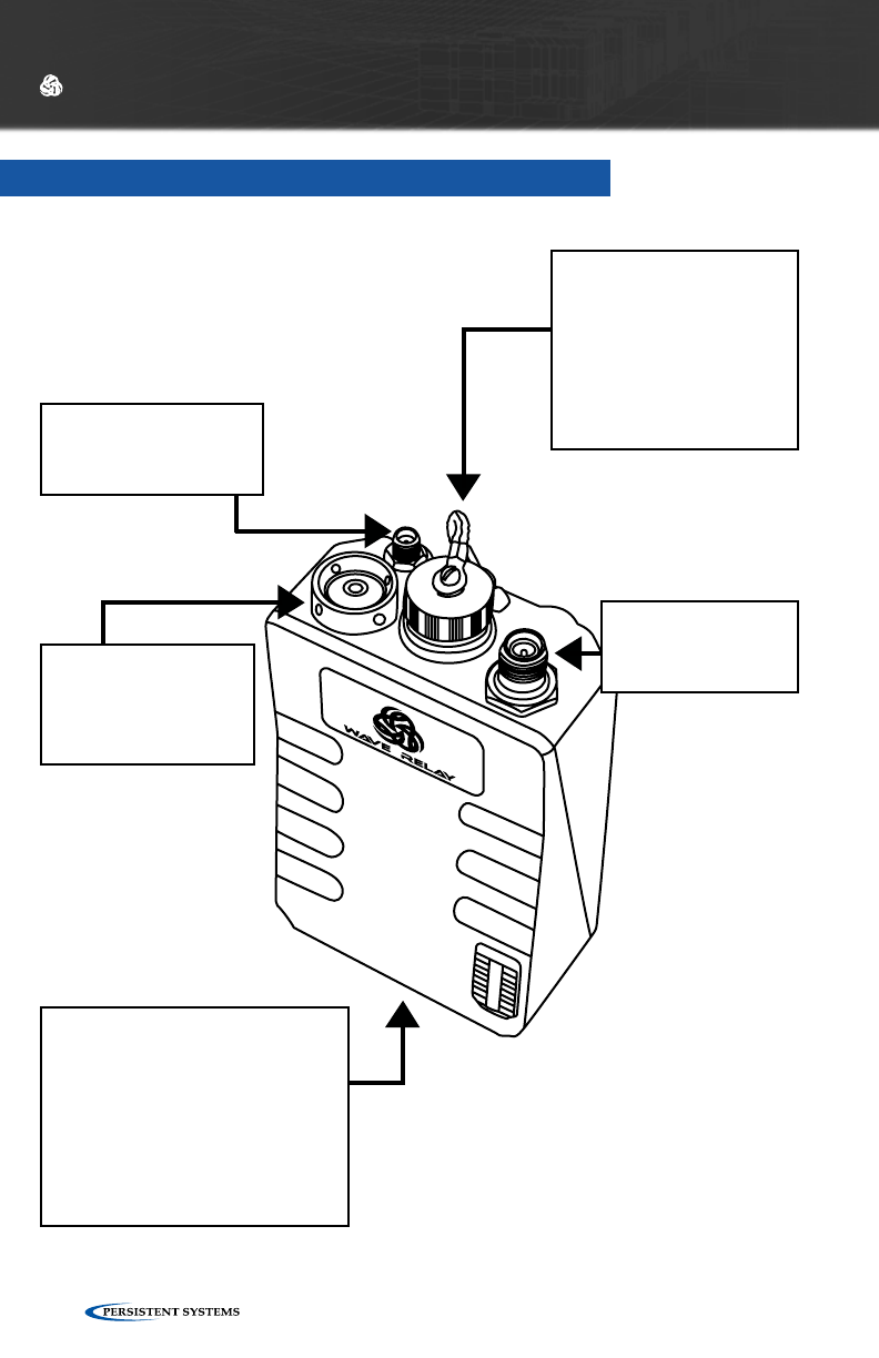
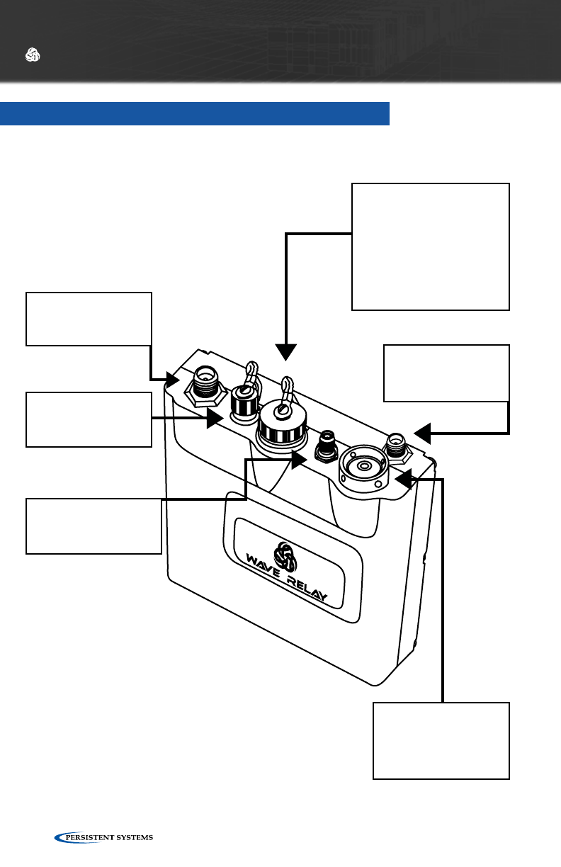
MAN PORTABLE UNIT — GEN4
DEVICE HARDWARE INTRODUCTION
GPS
3.3V Active Antenna
only (SMA)
RADIO 1
ANTENNA
(RP-TNC)
BATTERY TWIST-LOCK
CONNECTION
Included: BAT-06
Battery Eliminator: CBL-054
Compatible With:
PRC-148 Battery
PRC-152 Battery
POWER
10-48VDC
(48 VDC is PoE)
POWER/DEVICE I/O
(19-PIN)
Ethernet 1: 10.3.1.254
Ethernet 2: 10.3.2.254
Serial RS-232
PTT Audio
PoE: 10-48 VDC
PUSHBUTTON/LED
ZEROIZE: PRESS 3X
IN < 2
SECONDS
© 2010 - 2015 Persistent Systems, LLC – All Rights Reserved 11
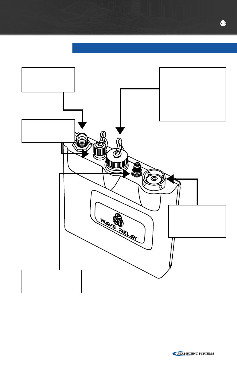
MAN PORTABLE UNIT — GEN3 SINGLE
DEVICE HARDWARE INTRODUCTION
RADIO 1
ANTENNA
(RP-TNC)
AUXILIARY
POWER (3-PIN)
10-48 VDC
GPS
3.3V Active Antenna
only (SMA)
POWER/DEVICE I/O
(19-PIN)
Ethernet 1: 10.3.1.254
Ethernet 2: 10.3.2.254
Serial RS-232
PTT Audio
PoE: 10 - 48 VDC
PUSHBUTTON/LED
ZEROIZE: PRESS 3X
IN < 2
SECONDS
© 2010 - 2015 Persistent Systems, LLC – All Rights Reserved12
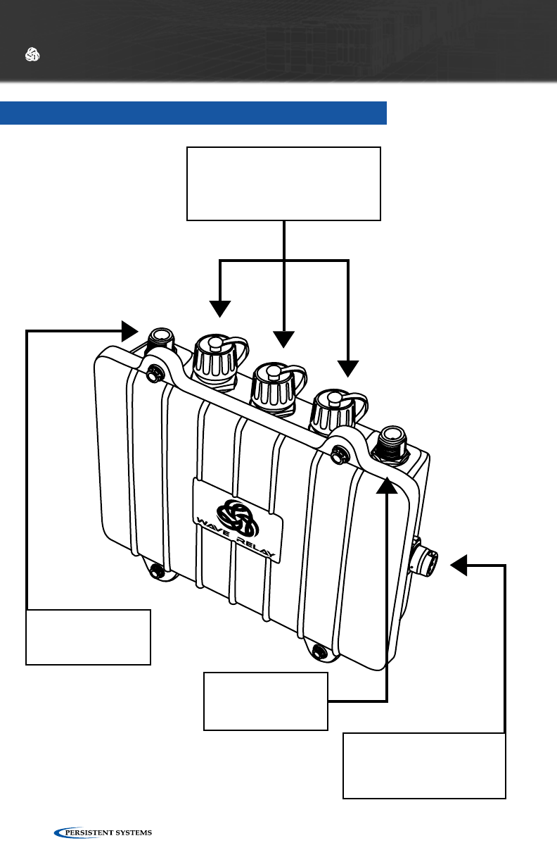
QUAD RADIO ROUTER
DEVICE HARDWARE INTRODUCTION
PUSH-TO-TALK (PTT) AU-
DIO (NATO 6-PIN CON-
NECTOR)
ETHERNET 2 SWITCH PORT
(RJ45)
CANNOT accept PoE
Ethernet 2 IP: 10.3.2.254
RADIO 2
ANTENNA
(N-type)
RADIO 1
ANTENNA
(N-type)
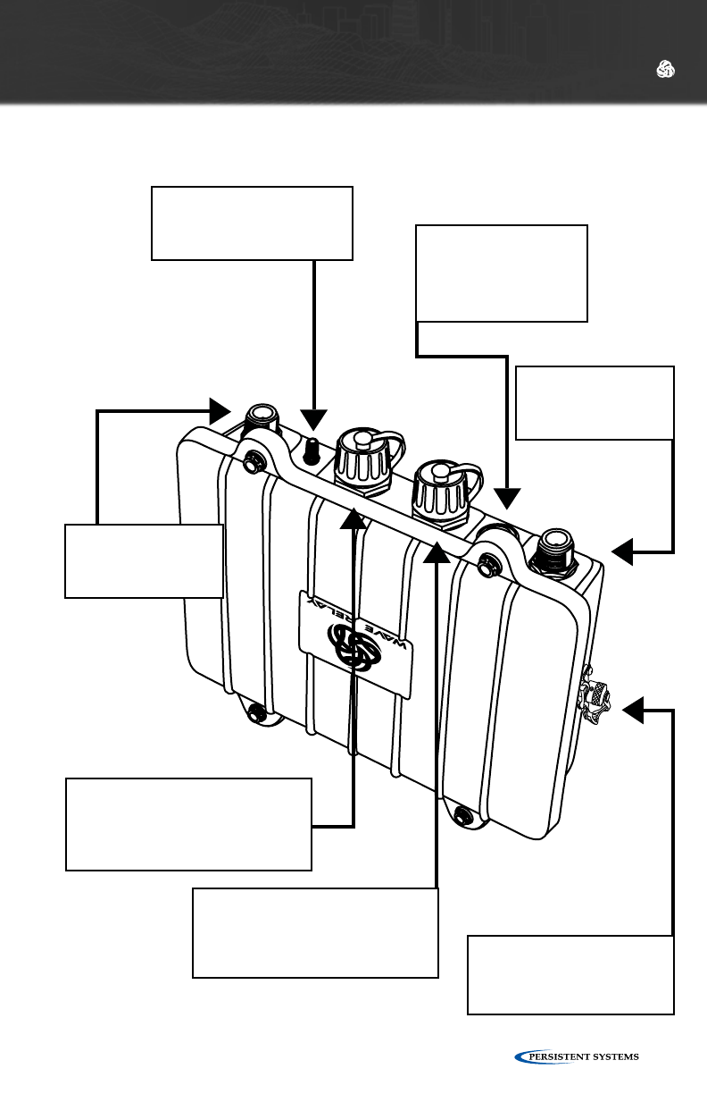
© 2010 - 2015 Persistent Systems, LLC – All Rights Reserved 13
DEVICE HARDWARE INTRODUCTION
ETHERNET 2 SWITCH PORT
(RJ45)
CANNOT accept PoE
Ethernet 2 IP: 10.3.2.254
RADIO 4
ANTENNA
(N-type)
GPS
3.3V Active Antenna only
(SMA)
RADIO 3
ANTENNA
(N-type)
AUXILIARY POWER/
SERIAL (4-PIN)
10-48 VDC
POWER/ETHERNET 1
(RJ45)
Accepts PoE, 10-48 VDC
Ethernet 1 IP: 10.3.1.254
PUSHBUTTON/LED
ZEROIZE: PRESS 3X
IN < 2
SECONDS
© 2010 - 2015 Persistent Systems, LLC – All Rights Reserved14
MAN PORTABLE UNIT — GEN3 DUAL
DEVICE HARDWARE INTRODUCTION
RADIO 2
ANTENNA
(RP-TNC)
RADIO 1
ANTENNA
(RP-TNC)
GPS
3.3V Active Antenna
only (SMA)
AUXILIARY
POWER (3-PIN)
10-48 VDC
POWER/DEVICE I/O
(19-PIN)
Ethernet 1: 10.3.1.254
Ethernet 2: 10.3.2.254
Serial RS-232
PTT Audio
PoE: 10 - 48 VDC
PUSHBUTTON/LED
ZEROIZE: PRESS 3X
IN < 2
SECONDS
© 2010 - 2015 Persistent Systems, LLC – All Rights Reserved 15
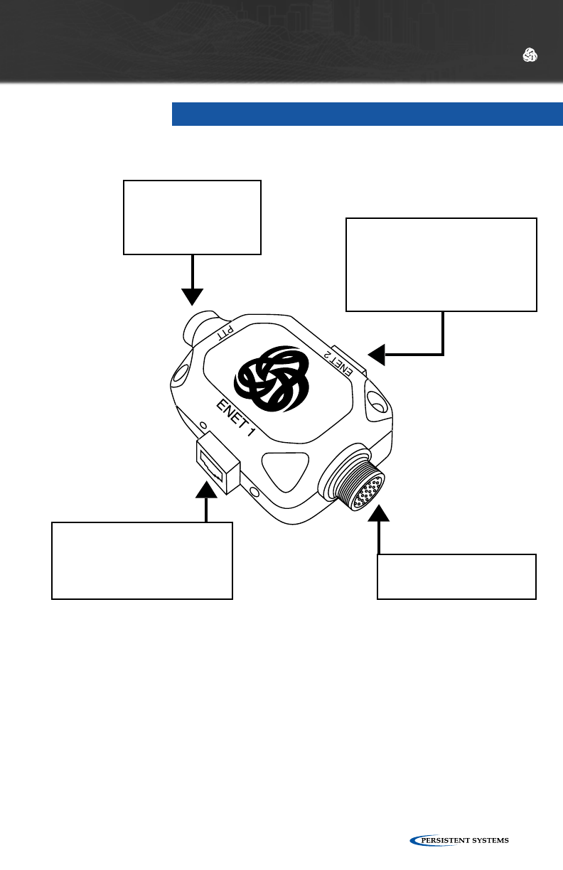
AID
POWER/ETHERNET 1
(RJ45)
Accepts PoE, 10-48 VDC
Factory Setup IP: 10.3.1.254
ETHERNET 2
(RJ45)
PoE,
10-48 VDC
Factory Setup IP: 10.3.2.254
TO MPU
(19-PIN)
PUSH-TO-TALK
(PTT) AUDIO
(NATO 6-PIN
CONNECTOR)
DEVICE HARDWARE INTRODUCTION

© 2010 - 2015 Persistent Systems, LLC – All Rights Reserved16
DEVICE
OPERATION
© 2010 - 2015 Persistent Systems, LLC – All Rights Reserved 17
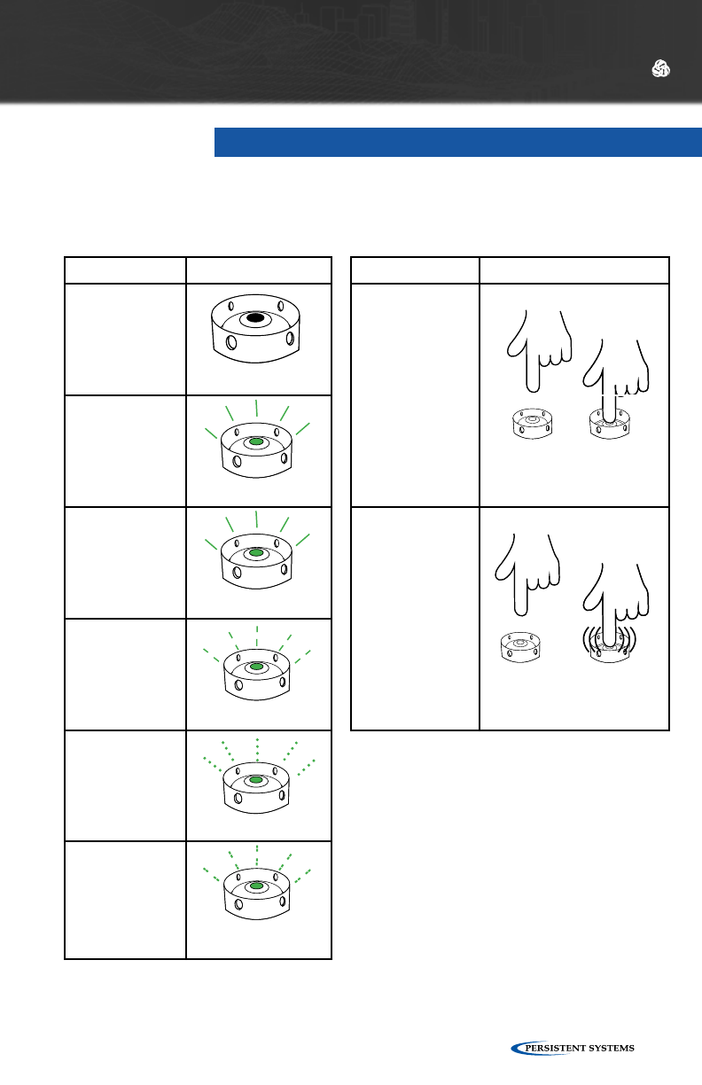
Low Battery
(MPU4 Only)
OFF 2 SEC,
ON .5 SEC
ON
ON
SLOW BLINK
FAST BLINK
OFF
HOLD
(1 second)
TAP 3 TIMES
(< 2 sec)
NOTE:
PUSHBUTTON/LED OPERATION
DEVICE OPERATION
STATE LED STATUS OPERATION INSTRUCTION
OFF ON/OFF Power
Boot Up
(30s - 2 mins)
Fully
Operational
Zeroize
Configuration
Required
Zeroize

© 2010 - 2015 Persistent Systems, LLC – All Rights Reserved18
When a node is shipped from the factory, it is in a state that requires configuration.
Nodes can be configured by using the Web Management Interface or through the
Management API.
Follow the steps under “Initial Node Configuration” to put the nodes into an opera-
tional state. The basic steps required to configure a node to an operational state are:
SET ENCRYPTION KEY
A key must be set in order for a node to communicate with other nodes in the net-
work. In order for two nodes to communicate, they must share a matching encryp-
tion key and crytpo mode.
SET CHANNEL
Each radio module on a node should be assigned a center frequency and channel
width. In order for two nodes to communicate, each node must have at least one
radio that shares the same center frequency and channel width.
SET IP ADDRESS
During node configuration, a node needs to be assigned a unique management IP
address. This management IP address is used for monitoring, configuration, and device
services (PTT, Google™ Earth, Tracking, RS-232, etc.).
In the event that two nodes are unable to communicate after initial configuration,
refer to the “Troubleshooting” section starting on page 104.
CONFIGURATION
DEVICE OPERATION

© 2010 - 2015 Persistent Systems, LLC – All Rights Reserved 19

© 2010 - 2015 Persistent Systems, LLC – All Rights Reserved20
WEB
MANAGEMENT
OVERVIEW
© 2010 - 2015 Persistent Systems, LLC – All Rights Reserved 21
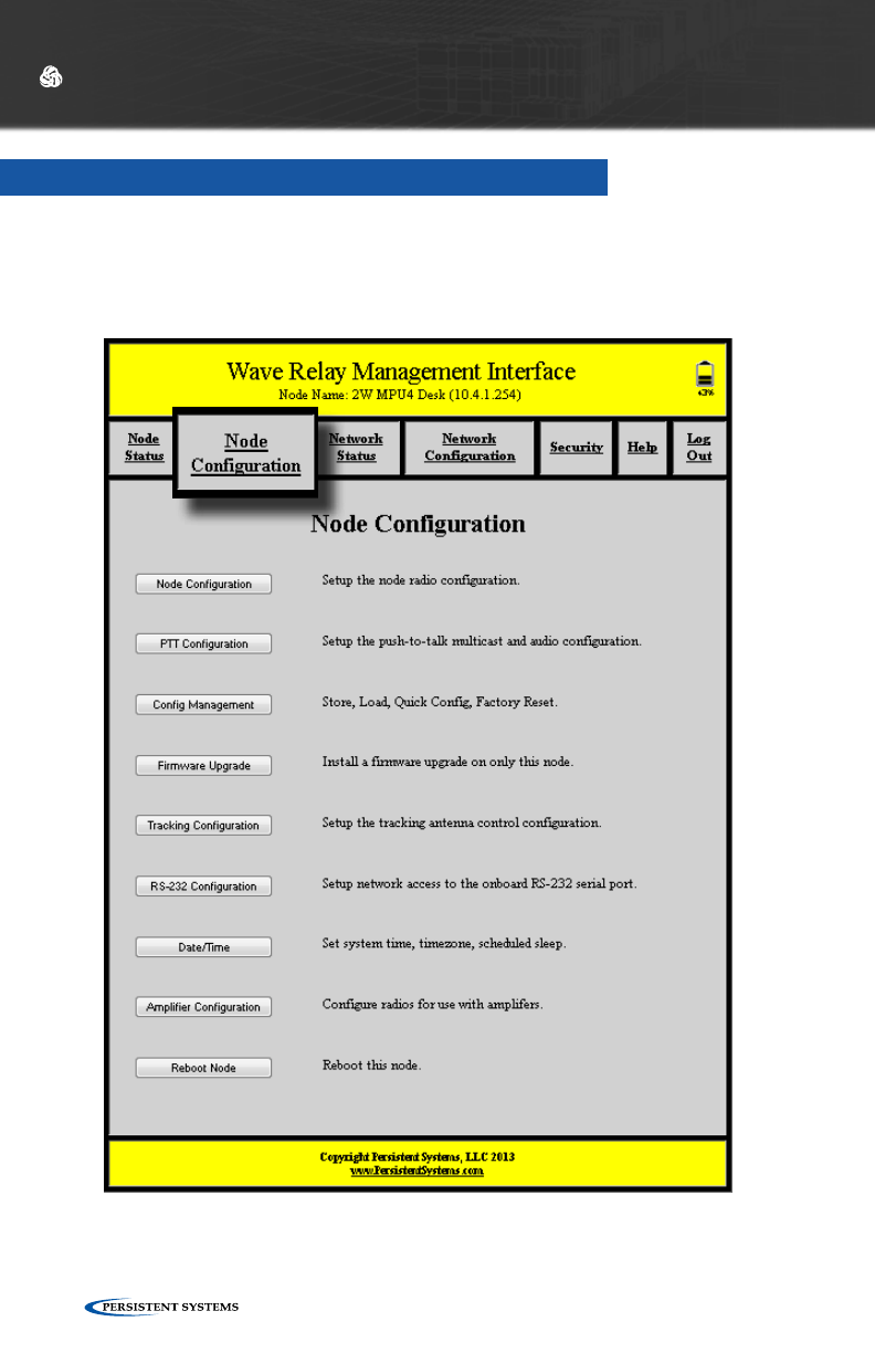
WEB MANAGEMENT OVERVIEW
WEB MANAGEMENT INTRODUCTION
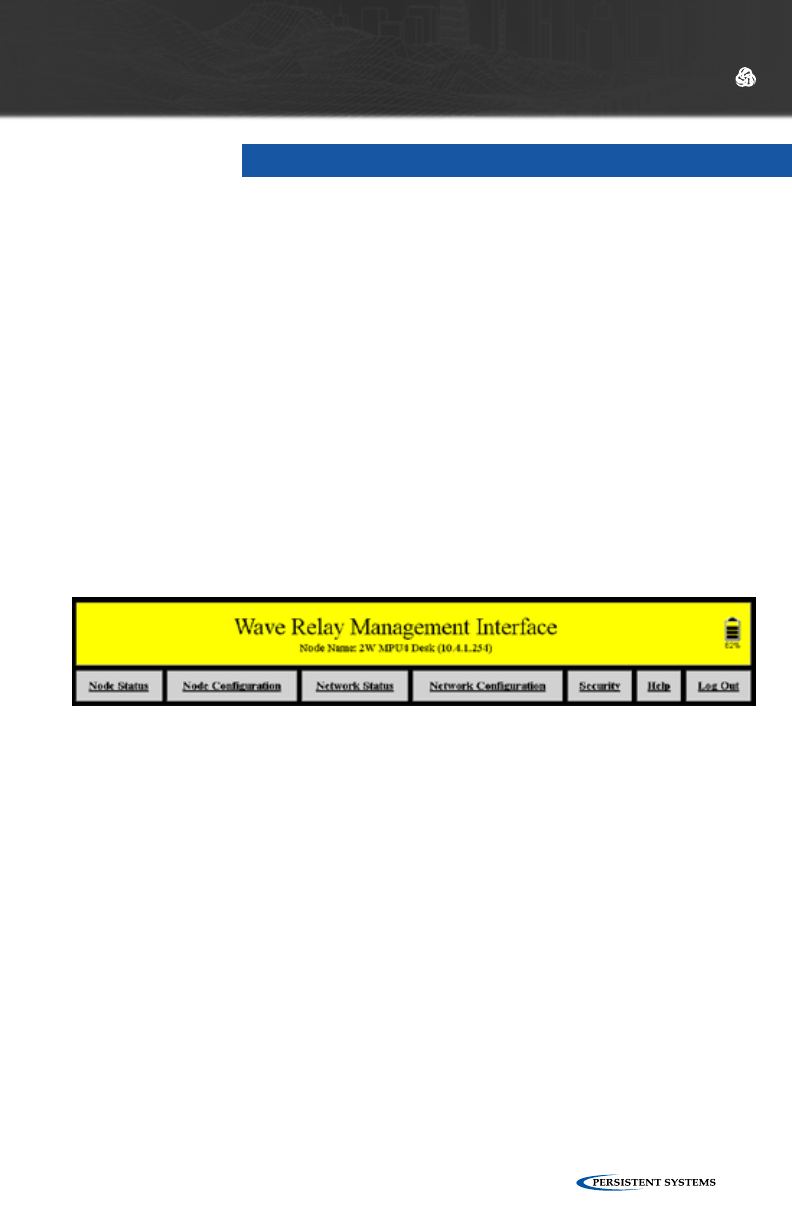
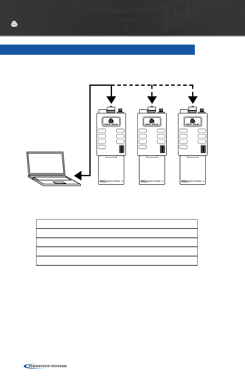
The Wave Relay® Web Management Interface enables users to configure and
monitor Wave Relay® units through a web browser. A navigation bar organizes
the Management Interface. The “Node Status” and “Node Configuration” tabs
pertain only to the node to which the management computer is connected
(either by Ethernet cable or by wireless), and the “Network Status” and “Network
Configuration” tabs pertain to the entire network of nodes.

© 2010 - 2015 Persistent Systems, LLC – All Rights Reserved22
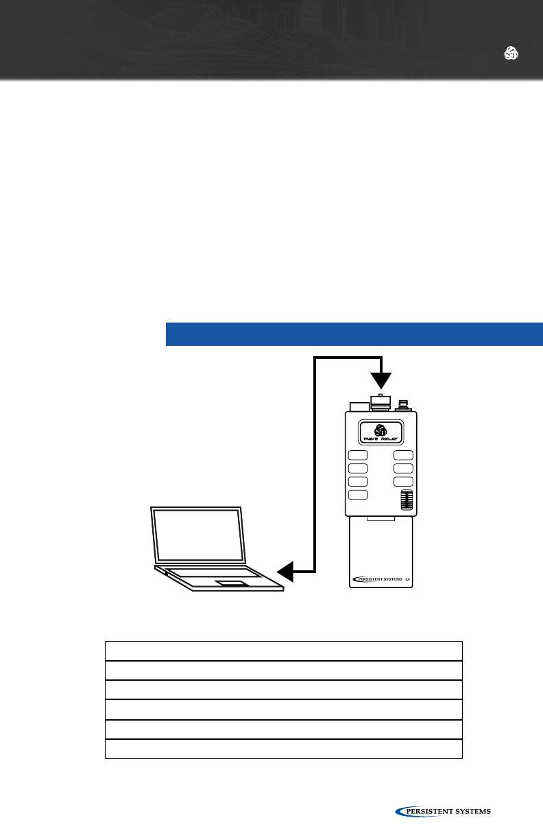
NODE CONNECTIVITY INFORMATION
Default Management Password
Ethernet 1 Factory Setup IP
Ethernet 2 Factory Setup IP
Password
10.3.1.254
10.3.2.254
•Factory Setup IP addresses are always accessible when directly connected to the radio. Use
Factory IPs any time you do not remember the management IP address of the radio.
•To connect to the Factory IP address, the management computer must be on the correct
IP subnet and wired to the correct Ethernet port on the node.
MANAGEMENT COMPUTER SETTINGS
IP Address
Subnet Mask
Default Gateway / Router
10.3.1.10
255.255.255.0
10.3.1.1
•To connect to the node using Ethernet 1, open a web browser and connect to
http://10.3.1.254.
•Each time you connect a new device, you may need to accept a security certificate before
you can enter the Web Management Interface.
•See next page for information on setting up the management computer.
ACCESSING THE WEB MANAGEMENT INTERFACE
WEB MANAGEMENT OVERVIEW
© 2010 - 2015 Persistent Systems, LLC – All Rights Reserved 23
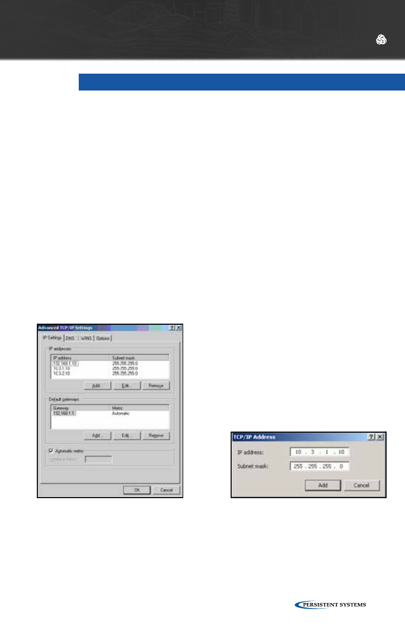
For your computer to be able to communicate with the Wave Relay®, it must have
an IP address that is in the same IP subnet mask as the Wave Relay®’s IP address.
A subnet mask of 255.255.255.0 means that the computer can communicate with
another device that has an IP address matching the first three numbers of its own IP
address.
No Default Gateway or DNS server configuration is required; however they can be
configured if necessary. Most computers are capable of having more then one IP
address configured on a single Ethernet adapter. It is recommended that you add all
three addresses to your wired Ethernet adapter so that you can easily manage your
network.
CONFIGURING YOUR COMPUTER’S IP ADDRESS
WINDOWS:
Start > Network (Right Click) >
Properties
Change Adapter Settings (Windows Vista
/ 7 only)
Local Area Connection (Right Click) >
Properties
Select Internet Protocol Version 4 (TCP/
IPv4)
Click Properties
Select Use the following IP Address
Click Advanced…
Click Add…
Enter IP Address and Subnet mask
Click Add and repeat for all IP
Addresses
LINUX:
[sudo] ifconfig eth0 10.4.1.10/24
[sudo] ip addr add 10.3.1.10/24 dev
eth0
[sudo] ip addr add 10.3.2.10/24 dev
eth0
WEB MANAGEMENT OVERVIEW
© 2010 - 2015 Persistent Systems, LLC – All Rights Reserved24
Recommended browsers are Firefox 3+, Internet Explorer 7+, and Google™ Chrome.
Internet Explorer 6 is not compatible with the most recent Web Management
Interface. If you are having difficulty connecting to the Web Management Interface,
make sure you are using one of the recommended browsers.
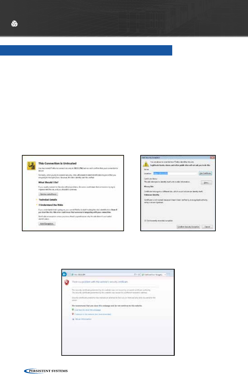
When connecting to the Web Management Interface, Firefox and Internet Explorer
may ask the user to accept a security certificate. Firefox and IE handle security cer-
tificates in different ways:
SECURITY CERTIFICATE WARNINGS
WEB MANAGEMENT OVERVIEW
FIREFOX DISPLAYS A PAGE
Click “I understand the risks” > ”Add Exception” > ”Confirm Security Exception.”
IE DISPLAYS A PAGE
Click the red X “Continue to this website (not recomended).”
© 2010 - 2015 Persistent Systems, LLC – All Rights Reserved 25
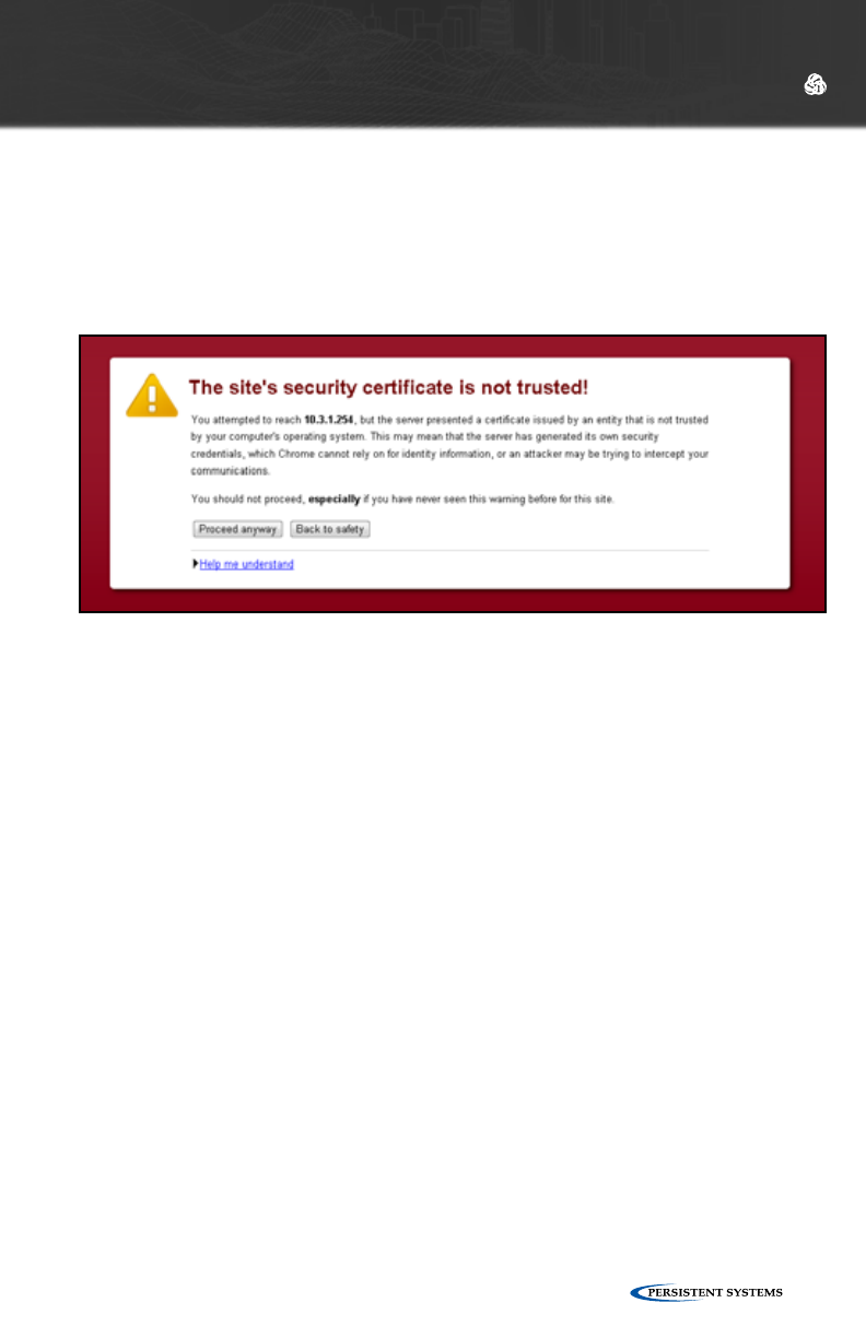
GOOGLE™ CHROME DISPLAYS A PAGE
1. Click the “Proceed anyway” button.
2. When the Web Management Interface loads, enter the management password
and click “Authenticate.” The default management password is “password”
which is set from the factory or after the key/configuration is zeroized by push-
ing the on/off button 3 time in less than 2 seconds.
WEB MANAGEMENT OVERVIEW

© 2010 - 2015 Persistent Systems, LLC – All Rights Reserved26
INITIAL
NODE
CONFIGURATION
© 2010 - 2015 Persistent Systems, LLC – All Rights Reserved 27
STEPS FOR CONFIGURING THE FIRST NODE
All nodes arrive set to factory default configuration. This section details the
recommended setup and custom configuration procedure for a set of identical
nodes, for example, a set of 50 MPU4s. In general, the procedure is completed as
follows:
1. Configure an individual node
2. Save the individual node’s configuration settings and key
3. Load key and the saved configuration settings into remaining nodes
4. Verify communication among the nodes
QUICK CONFIGURATION
If the network administrator provides a node configuration file, use it to facilitate
quick device configuration. Please refer to Section “Quick Setup.” If a node con-
figuration file has been provided, skip to the “Steps for Configuring the Remaining
Nodes” section.
INITIAL NODE CONFIGURATION
STEPS FOR CONFIGURING THE FIRST NODE
1. Configure Network Defaults
2. Customize Node Name and IP Address To Be Unique
3. Configure Radio to Use Defaults
4. Setup Node List
5. Store Configuration File
6. Set and Save Security Settings
© 2010 - 2015 Persistent Systems, LLC – All Rights Reserved28
INITIAL NODE CONFIGURATION
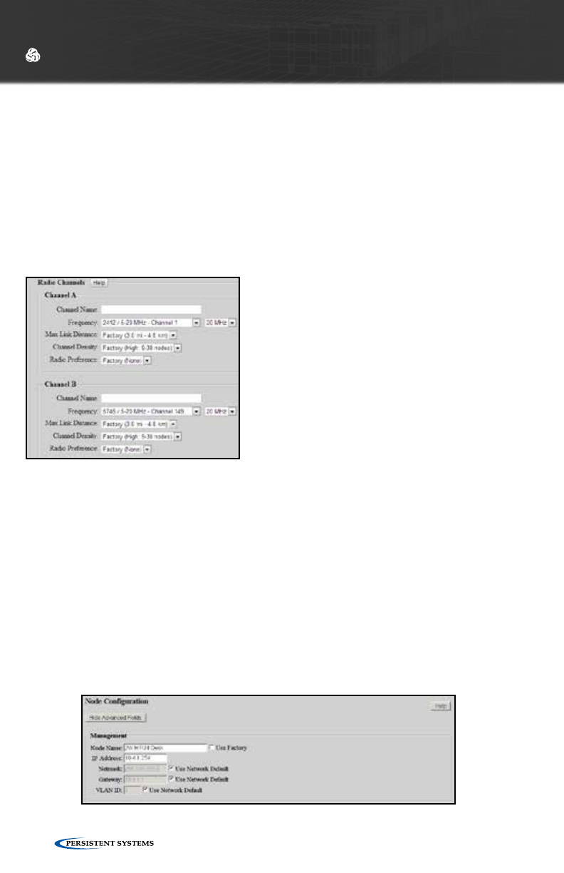
STEP 2: CUSTOMIZE NODE NAME AND IP ADDRESS TO BE UNIQUE
Each node in the network should be assigned a unique node name and IP address to
facilitate management and network operations.
1. Click “Node Configuration” > “Node Configuration.”
2. Insert the new name and IP Address in the indicated fields.
3. Set the gateway to match the subnet of the node’s IP address.
4. Click the “Save & Reconfigure Unit” button at the bottom of the page.
5. Load the key and saved configuration file into remaining nodes. Customize the
Node Name and IP address for each node, then click the “Save & Reconfigure
Unit” button at the bottom of the page.
6. Ensure that node names and IP addresses of all nodes are unique.
STEP 1: CONFIGURE NETWORK DEFAULTS
Network Defaults are settings that will be used to manage the configuration of the
network. Up to 16 different default Channel settings are able to be configured.
1. Click “Network Configuration” > “Network Defaults.”
2. Choose the settings you would like to use for your network for each Channel.
3. Click the “Save to Network” button at the bottom of the page.
For more information on setting Network Defaults, refer to the section “Network
Configuration > Network Defaults.”
WARNING!
For units branded with an FCC label and FCC ID,
only the provided antenna or equivalent type and
gain can be used: this device must comply with
Part 15 of the FCC rules.
FCC branded devices will be limited so users can-
not set output power levels outside of those certi-
fied under the FCC rules.
FCC test results and reports can be provided by
Persistent Systems, LLC upon request.
For more information, please contact Persistent Sys-
tems, LLC Quality/Compliance personnel.
© 2010 - 2015 Persistent Systems, LLC – All Rights Reserved 29
STEP 3: CONFIGURE RADIO TO USE DEFAULTS
The node must be configured to use the appropriate Network Defaults in order for
the node to be managed by changes to the Network Configuration.
1. Click “Node Configuration” > “Node Configuration.”
2. Select the appropriate Network Defaults in the drop down menus.
3. Click the “Save & Reconfigure Unit” button at the bottom of the page.
For more information, see section “Configuring Radio to Use Defaults.”
INITIAL NODE CONFIGURATION
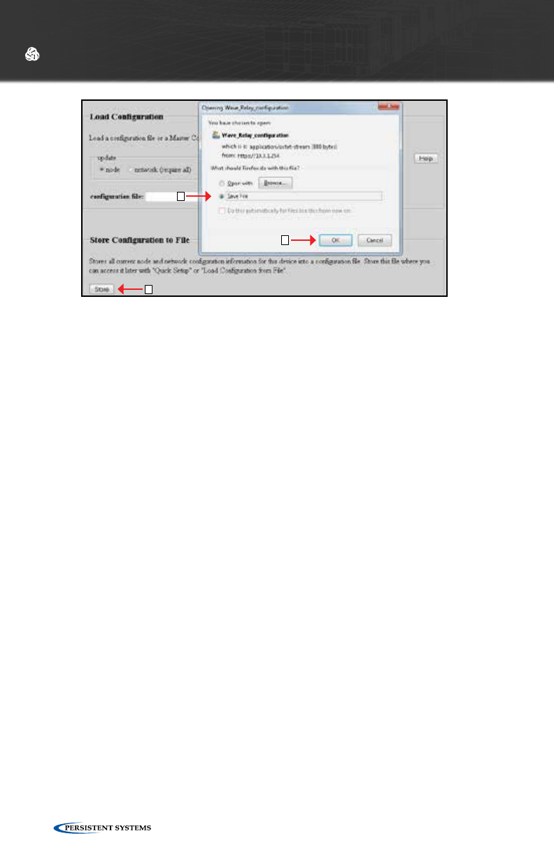
STEP 5: STORE CONFIGURATION FILE
Device settings (both Node Configuration and Network Configuration settings) can
be saved to a configuration file. The configuration file serves as a backup for device
settings and provides the ability to easily transfer settings from one node to another.
1. Ensure Network Configuration and Node Configuration settings are set as
desired.
2. Click “Node Configuration” > “Config Management.”
3. Click the “Store” button. A prompt will appear to choose where to save the
configuration file. Note specifically that this file contains settings (both Network
Configuration and Node Configuration settings) for the current device only.
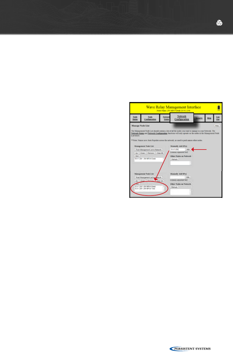
STEP 4: SETUP NODE LIST
The Node List is a list of IP Addresses of
nodes managed by the Web Management
Interface.
1. Click “Network Configuration” >
“Network Node List.”
2. Enter the IP Address of a node in the
“Manually Add IP(s)” field and click
“Add” to add the node associated with
that IP Address to the Node List. Nodes
may also be added from the “Other
Nodes on Network” window if they are
detected by the network. These nodes
may be added individually with the
“Selected IPs” button or all at once with
the “All” button.
3. Repeat this process for every node to be managed.
4. With all new nodes programmed and on, ensure that all nodes are on the
Network Node List.
5. Click the “Push Management List to Network” button. This function will copy
the node list to each node in the network. Only nodes in the node list will
be affected by Network Configuration functions. Pushing the node list to the
network allows network-wide settings to be managed from any node in the
network.
© 2010 - 2015 Persistent Systems, LLC – All Rights Reserved30
INITIAL NODE CONFIGURATION
2
3
1
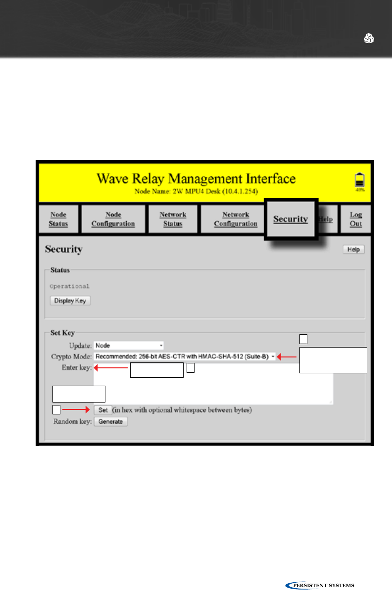
STEP 6: SET AND SAVE SECURITY SETTINGS
A node will not function properly unless it has a valid key. If the “Security” tab in the
Web Management Interface is blinking red, then a proper key has not been set. All
nodes in a network must use the same Crypto Mode AND Key in order to
communicate.
1. Select the “Security” tab in the Web Management Interface.
2. Select a Crypto Mode to match your network requirements.
3. Once the Crypto Mode is set, enter a key value into the field and click “Set” or
click “Generate” to generate a random key. The new key information is stored
to the node or the network based on the setting in the “Update” menu.
For more information on Security information and selecting Crypto Mode options,
refer to the “Security” section.
The key will NOT be stored in the configuration file. The key must be stored sepa-
rately.
1. Click the “Display Key” button.
2. Select OK on the warning to open the key. Since the key is displayed in plain-
text, only open the key in a secure environment.
3. Copy the key to a text file in a secure place on your management computer.
© 2010 - 2015 Persistent Systems, LLC – All Rights Reserved 31
INITIAL NODE CONFIGURATION
Ensure all nodes are
using the same
Crypto Mode
Enter your key
here
Click here after
entering key
1
2
3
© 2010 - 2015 Persistent Systems, LLC – All Rights Reserved32
STEPS FOR CONFIGURING THE REMAINING NODES
1. Load Configuration File into All Other Nodes
2. Load Key into All Other Nodes
3. Verify Nodes are Communicating
4. Push Node List to Network
5. Set Management Password
STEPS FOR CONFIGURING THE REMAINING NODES
INITIAL NODE CONFIGURATION

© 2010 - 2015 Persistent Systems, LLC – All Rights Reserved 33
STEP 1: LOAD CONFIGURATION FILE INTO ALL OTHER NODES
When setting up a network of new nodes from the factory, use the configuration
file saved in the “Store Configuration File” step to upload the settings from the
previously configured node into the new node. During this process, node specific
settings (including IP Address, Radio Name, and other radio specific settings) can
be configured separately for each node while preserving all other settings from the
configuration file.
1. Click “Node Configuration” > “Config Management.”
2. In the Load Configuration menu, select “network (require all)” or “network (any
available)” to upload configuration settings to all nodes in the network. The
“network (require all)” setting will require all nodes in the network be available
for any changes to be applied. If not all nodes are available, no changes will be
applied. The “network (any available)” setting will apply changes to available
nodes only.
3. Click the “Choose File” button to find the the configuration file saved in the
“Store Configuration File” step.
4. Click the “Load” button to upload configuration settings to other nodes in the
network.
STEP 2: LOAD KEY INTO ALL OTHER NODES
The security key is NOT stored in the configuration file. You must load the key
separately.
1. Select the “Security” tab in the Web Management Interface.
2. In the “Set Key” box, select “network (require all)” or “network (any available)”
to upload the security key to all nodes in the network. The “network (require
all)” setting will require all nodes in the network be available for any changes
to be applied. If not all nodes are available, no changes will be applied. The
“network (any available)” setting will apply changes to available nodes only.
3. Select the Crypto Mode chosen in Step 6 of First Node Configuration from the
drop-down menu.
4. Copy the security key from the text file saved in Step 6 of First Node Configura-
tion and paste the security into the “Enter key” field. All nodes MUST have the
same security key to communicate.
INITIAL NODE CONFIGURATION
© 2010 - 2015 Persistent Systems, LLC – All Rights Reserved34
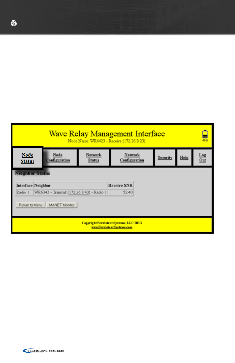
STEP 3: VERIFY NODES ARE COMMUNICATING
After nodes have been configured, the connectivity of the nodes should be checked.
1. Ensure that all nodes are turned on, that at least one radio on each node has an
antenna and is set to the same channel as the other nodes, and that each node
has the same key.
2. Access one of the nodes and verify connectivity to all the nodes. Click “Node
Status” > “Neighbor Status.” The figure below displays the Node Neighbor Status,
which shows which of the node’s radios are communicating with other radios. This
figure shows that Radio 1 is communicating with one other radio in a neighbor
node.
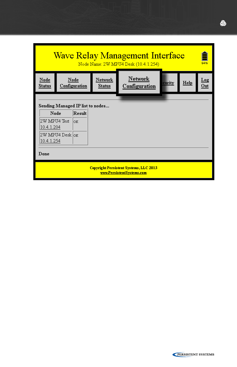
STEP 4: PUSH NODE LIST TO NETWORK
To be able to control configuration settings for the entire network from any node in
the network rather than just this node, the user must push the Node List to all other
nodes in the network.
1. Click “Network Configuration” > “Network Node List” > “Push Management
List to Network.” This function will share the Node List configured on this node
with all nodes in the Node List.
INITIAL NODE CONFIGURATION
© 2010 - 2015 Persistent Systems, LLC – All Rights Reserved 35
STEP 5: SET MANAGEMENT PASSWORD
After all nodes have been configured, the management password should be
changed.
1. Click “Network Configuration” > “Network Password.”
2. Enter the old password in the “Old Password” field.
3. Enter the new password in both “New Password” fields.
4. Click the “Change” button to change the management password. The
management password will be changed on all nodes in the node list. The
current node list is displayed at the bottom of the page.
INITIAL NODE CONFIGURATION

© 2010 - 2015 Persistent Systems, LLC – All Rights Reserved36
The Node List contains a list of nodes specified by IP Address that are controlled by
the Web Management Interface. Any function that resides under Network Status
or Network Configuration operates on, and only on, the nodes listed in the node list.
In the context of Wave Relay®, the network is defined as the set of nodes for which
routing is possible. These nodes do not need to be specified in the Node List. By
contrast, the Node List defines a set of Managed Nodes that are managed by the
network operations in the Web Management Interface. That list, however, does
not restrict connectivity between nodes specified in the Node List and nodes not
specified in the Node List. Therefore, the Node List is just a management tool that
defines the list of nodes on which network management functions operate.
In general, the Node List should be updated whenever the network changes in
order to ensure that every node has complete and current information and is able to
be monitored and controlled by the network operations in the Web Management
Interface.
NODE LIST
NETWORK VS MANAGED NODES DEFINED
INITIAL NODE CONFIGURATION

© 2010 - 2015 Persistent Systems, LLC – All Rights Reserved 37
Network Upgrade installs new firmware versions on large numbers of nodes with
one operation. Since network upgrades function on all nodes in the Node List, make
sure the Node List is complete and current before performing a Network Upgrade.
1. Click “Network Configuration” > “Network Upgrade.”
2. Browse and select the appropriate upgrade file.
3. Check or uncheck “Require All.” If checked, the update will be installed if
and only if all the nodes in the Node List are accessible. If unchecked, the
update will be installed to only those nodes in the Node List that are accessible.
Network Upgrades will cause nodes to be reconfigured, an operation that
causes a period of downtime. Do not perform Network Upgrades during
mission critical operations that cannot tolerate such disruptions. Under such
situations, perform Network Upgrades only during scheduled maintenance or
other appropriate times.
4. Click the “Upload” button to upgrade firmware for all nodes in the Node List.
NOTE: When upgrading or downgrading a node’s firmware, it is normal for the LED
to turn off for 30 seconds then turn on.
Do not unnecessarily disturb devices during a Network Upgrade. Loss of power
during the Network Upgrade can permanently damage a device.
To receive the latest firmware update:
1. Connect to: http://www.persistentsystems.com/requestfirmwareupdate.php
2. Fill out all fields on the page.
3. Ensure the “Receive Firmware” box is checked.
4. Click the “Submit Query” button.
NETWORK UPGRADE
INITIAL NODE CONFIGURATION

© 2010 - 2015 Persistent Systems, LLC – All Rights Reserved38
WEB
MANAGEMENT
INTERFACE
REFERENCE
© 2010 - 2015 Persistent Systems, LLC – All Rights Reserved 39
WEB MANAGEMENT INTERFACE REFERENCE
The “Node Status” tab in the Web Management Interface contains node-specific
information for the individual node that the user is connected to.
NODE STATUS
© 2010 - 2015 Persistent Systems, LLC – All Rights Reserved40
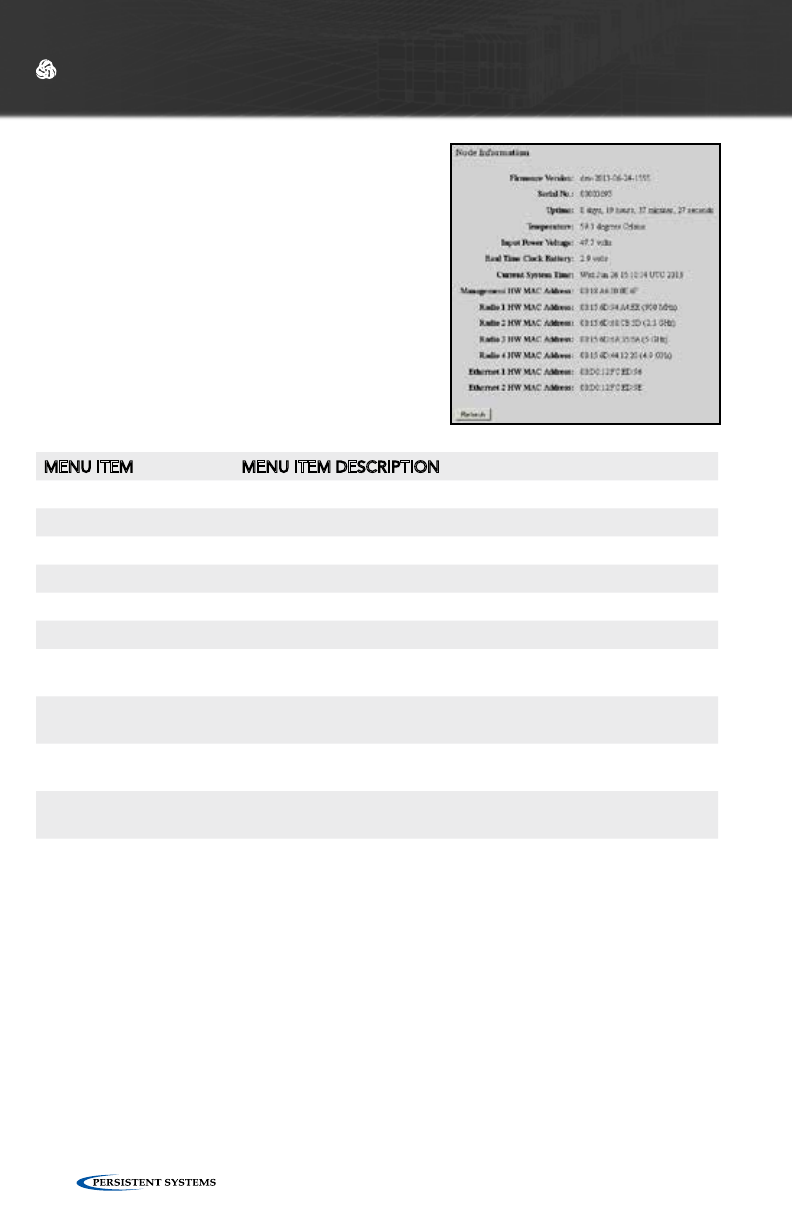
MENU ITEM MENU ITEM DESCRIPTION
Firmware Version Firmware version on node
Serial No. Serial number of node
Uptime Operating time since last node power on or reboot
Temperature Temperature of node
Input Power Voltage Voltage supplied to node
Real Time Clock Battery Voltage of real-time-clock keep-alive battery (on units with RTC)
Current System Time Current system time of node (in both UTC and current time zone
if not UTC)
Management HW MAC
Address
MAC Address for Management Hardware of node
Radio X HW MAC Ad-
dress
MAC Address and bandwidth for each radio installed in node (X
will vary based on number of radios installed)
Ethernet X HW MAC
Address
MAC Address for each ethernet port in node (X will vary based
on number of Ethernet ports in node)
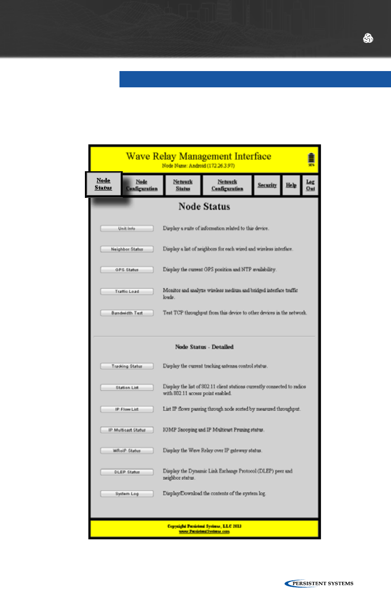
UNIT INFO
Unit Info displays a list of hardware and software
information related to the node.
WEB MANAGEMENT INTERFACE REFERENCE
© 2010 - 2015 Persistent Systems, LLC – All Rights Reserved 41
WEB MANAGEMENT INTERFACE REFERENCE
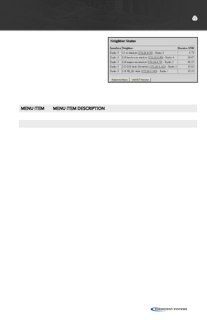
MENU ITEM MENU ITEM DESCRIPTION
Interface Each interface in use on node
Neighbor Name, IP address, and interface of each neighbor node
Receive SNR Signal-to-Noise Ratio at which local node hears remote node
NEIGHBOR STATUS
Neighbor Status page displays a list of
neighbor nodes that the current node
has an RF connection with.
If the neighbor node is in the node list
and the “Update Network” operation
has been performed, the node’s name,
IP address, and radio interface will be
displayed. Otherwise, the neighbor
node’s MAC address will be displayed.
© 2010 - 2015 Persistent Systems, LLC – All Rights Reserved42
WEB MANAGEMENT INTERFACE REFERENCE
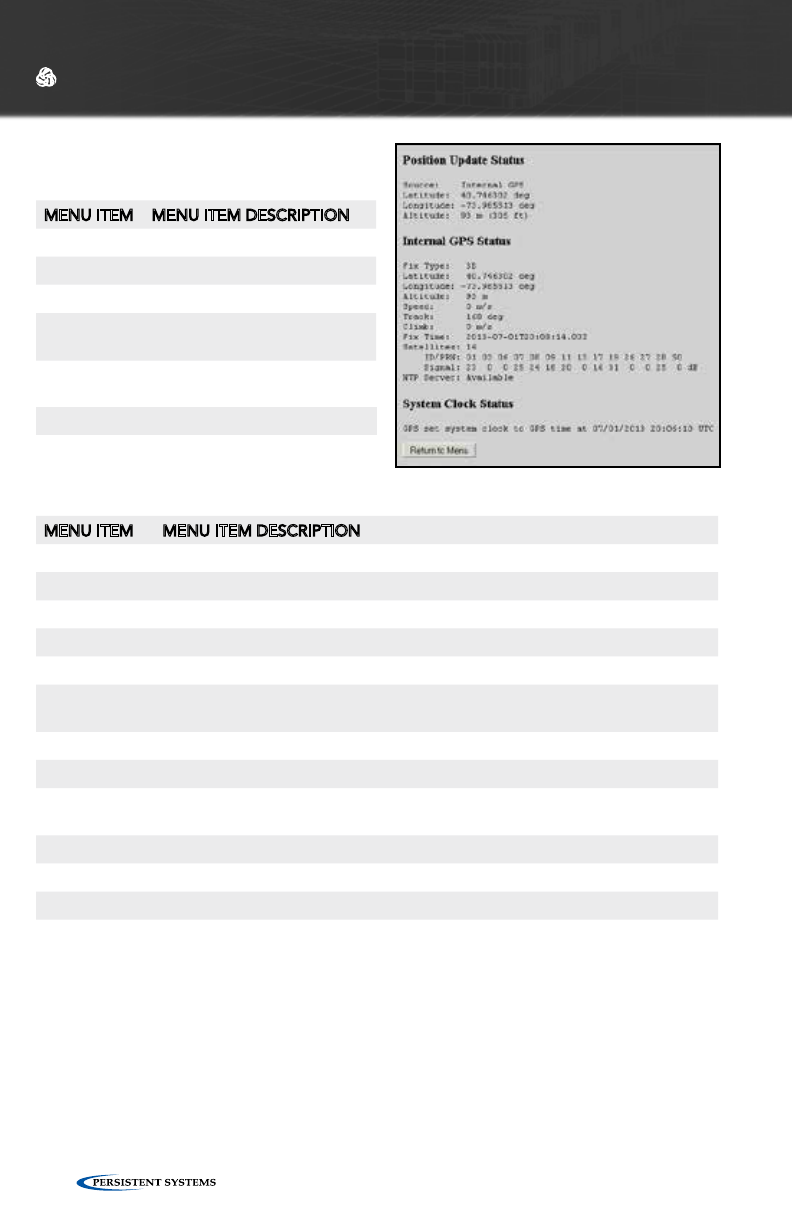
Internal GPS Status:
MENU ITEM MENU ITEM DESCRIPTION
Fix Type How node is connected (3D, 2D, or none)
Latitude Latitude of current node
Longitude Longitude of current node
Altitude Altitude above sea level of current node
Speed Speed of node (m/s) in the horizontal plane
Track Path of travel with respect to the Earth expressed in degrees - 000 degrees
is North (angle increases clockwise through 360 degrees)
Climb Speed of node (m/s) in the vertical plane
Fix Time When node obtained a satellite fix
Number of
satellites
Number of satellites node is connected to
ID/PRN ID/PRN of each satellite node is connected to
Signal Strength of the connection between node and each satellite
NTP Server Status of the NTP server (available or unavailable)
GPS STATUS
Position Update Status:
MENU ITEM MENU ITEM DESCRIPTION
Source GPS information source
Latitude Latitude of current node
Longitude Longitude of current node
Altitude Altitude above sea level of
current node
System Clock Status:
When the system clock was set by GPS
Current system time
© 2010 - 2015 Persistent Systems, LLC – All Rights Reserved 43
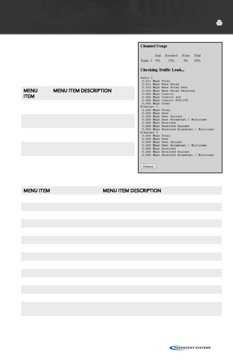
TRAFFIC LOAD
Traffic load monitors and analyzes the trafffic
load on the wireless and wired networking
interfaces on the node.
Channel Usage:
MENU
ITEM
MENU ITEM DESCRIPTION
Sent Transmission duty cycle of wireless
medium usage
Received Receiving transmission duty cycle of
wireless medium usage
Noise Duty cycle of wireless medium us-
age: Occupied by noise
Used Total duty cycle of wireless medium
usage
WEB MANAGEMENT INTERFACE REFERENCE
Checking Traffic Load:
MENU ITEM MENU ITEM DESCRIPTION
Mbps Total Total Mbps used on this interface
Mbps Wave Relay®Total Mbps used by Wave Relay®
Mbps Wave Relay® Sent Mbps used by Wave Relay® to send
Mbps Wave Relay® Received Mbps used by Wave Relay® to receive
Mbps Control Total Mbps used for control functions
Mbps Control Ack Mbps used to control ACK
Mbps Control RTS/CTS Mbps used to control RTS/CTS
Mbps Other Mbps used for other functions
Mbps Sent Total Mbps used for all transmissions
Mbps Sent Unicast Mbps used for Unicast transmissions
Mbps Sent Broadcast/Multicast Mbps used for Broadcast/Multicast transmissions
Mbps Received Total Mbps used to receive all transmissions
Mbps Received Unicast Mbps used to receive Unicast transmissions
Mbps Received Broadcast/Multi-
cast
Mbps used to receive Broadcast/Multicast transmis-
sions
© 2010 - 2015 Persistent Systems, LLC – All Rights Reserved44
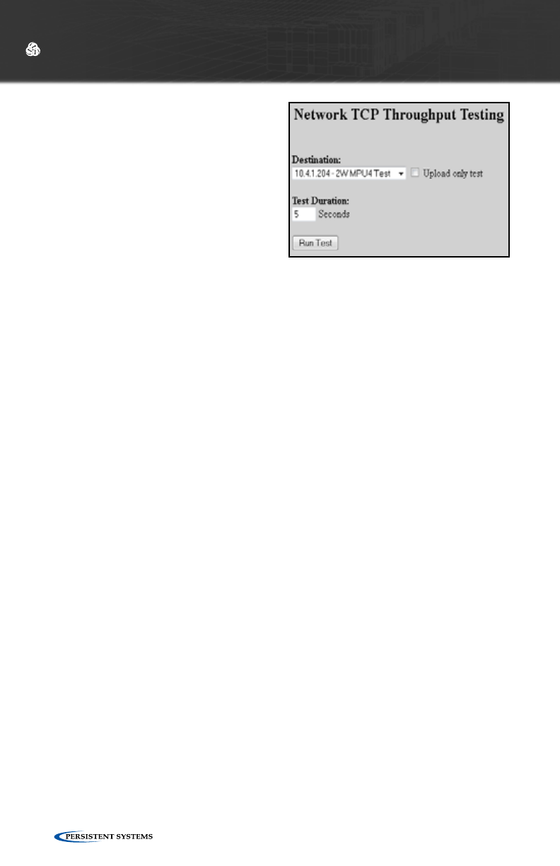
BANDWIDTH TEST
Bandwidth Test is a tool for testing the
data throughput from the node to another
node in the network. It is recommended
to perform at least a 5 second throughput
test.
Wave Relay® nodes run a TCP iPerf server.
To perform a TCP throughput test through
the iPerf server, use the command “iperf
-c X” (X is the IP address of the node) from
the command line.
WEB MANAGEMENT INTERFACE REFERENCE
TO PERFORM A THROUGHPUT TEST:
1. Select destination node for throughput test from drop-down menu. Desired
destination node must be in Node List for it to appear on this menu.
2. Check or uncheck “Upload only test.” If this box is checked, throughput test will
only test upload to destination node.
3. Enter desired throughput test duration (in seconds) into “Test Duration” field.
Caution: during tests of long duration, data will continue to be sent for the full
specified duration even if a different data flow is started or the web browser is
exited.
WARNING: Windows has known issues running iPerf and does not give true
bandwidth readings. Contact Persistent Systems for more information.
© 2010 - 2015 Persistent Systems, LLC – All Rights Reserved 45
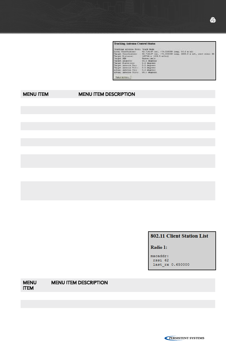
TRACKING STATUS
Tracking Status displays relevant an-
tenna tracking status and diagnostic
information.
MENU ITEM MENU ITEM DESCRIPTION
Tracking Antenna Mode Tracking configuration of node
Local Coordinates Coordinates of tracking node
Target Coordinates Coordinates of tracked node
Target Distance Distance of tracked node from tracking node
Target SNR Signal-to-Noise ratio between tracking node and tracked node
Target Azimuth Azimuth of tracked node
Target Elevation Elevation of tracked node
Target Antenna Pan Calculated necessary horizontal position of Tracking Antenna in
degrees clockwise from North
Target Antenna Tilt Calculated necessary vertical position of Tracking Antenna
expressed in degrees
Actual Antenna Pan Current horizontal position of Tracking Antenna in degrees
clockwise from North (will only pan when Target changes at least
0.5 degrees from Actual)
Actual Antenna Tilt Current vertical position of Tracking Antenna in degrees (will only
tilt when Target changes at least 0.5 degrees from Actual)
STATION LIST
Station List displays the list of 802.11 client stations
currently connected to radios with the 802.11 access
point feature enabled.
MENU
ITEM
MENU ITEM DESCRIPTION
macaddr MAC Address of client device connected to access point
rssi Strength of signal to client device
last_rx Time (in seconds) since a packet was last received
WEB MANAGEMENT INTERFACE REFERENCE
© 2010 - 2015 Persistent Systems, LLC – All Rights Reserved46
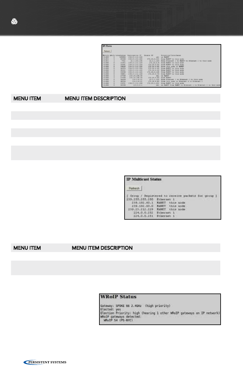
IP FLOW LIST
IP Flow List lists IP data flows
passing through node sorted by
measured throughput.
IP MULTICAST STATUS
IP Multicast Status displays IGMP Snoop-
ing and IP Multicast Pruning status. This
feature shows a table with a row for each
multicast group, displaying an “F” if that
group is forwarded over the MANET, or a
“-” if it is not.
There are known issues with IGMP in Windows XP.
WEB MANAGEMENT INTERFACE REFERENCE
MENU ITEM MENU ITEM DESCRIPTION
Mbit/s Speed of each IP data flow in Mbps
Pkt/s Number of packets transferred each second for each IP data flow
Total bytes Number of bytes transferred for each IP data flow
Destination IP IP address of destination node
Source IP IP address of source node
Direction/Interfaces Direction of and interfaces used by each IP data flow (MANET, Ether-
net X, or this node)
MENU ITEM MENU ITEM DESCRIPTION
Group Multicast address of nodes connected to managed node
Registered to receive
packets for group
Interface used to receive data for each multicast address (Ether-
net X or MANET)
WRoIP STATUS
WRoIP Status displays the Wave
Relay® over IP gateway status.
© 2010 - 2015 Persistent Systems, LLC – All Rights Reserved 47
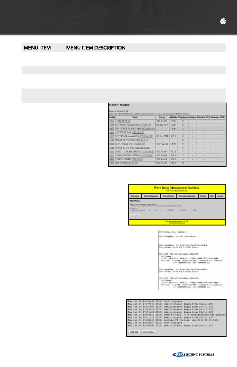
SYSTEM LOG
The System Log page displays a history
of node management operations. The
“Refresh” button reloads the system
log to add more recent operations. The
“Download” button allows the user to
download the log to the computer.
DYNAMIC LINK EXCHANGE PROTOCOL
(DLEP) STATUS
The DLEP Status page shows if the DLEP
services is running, what port, who it’s
connected to and the status of it. It also
contains the status of the associated
neighbors.
It is also possible to set the status of DLEP on the Cisco
Router side.
WEB MANAGEMENT INTERFACE REFERENCE
MENU ITEM MENU ITEM DESCRIPTION
Gateway Which gateway the node is connected to as well as the priority of that gate-
way
Elected Whether the gateway is elected or not
Election Priority Election priority of the gateway over other gateways/number of other WRoIP
gateways on the IP network.
WRoIP gateways
detected
Displays names of detected WRoIP gateway nodes
When connected to a WRoIP-con-
figured node, the Neighbor SNR
status page for the node will NOT
display other nodes connected
over WRoIP. Instead, these nodes
will be displayed on the MANET
Monitor page with a SNR of “-”
since they are not connected via
radio.
For detailed information, see the
Cloud RelayTM Manual
© 2010 - 2015 Persistent Systems, LLC – All Rights Reserved48
WEB MANAGEMENT INTERFACE REFERENCE
The “Node Configuration” tab in the Web Management Interface contains
configuration options for managing an individual node. Click “Node Configuration”
> “Node Configuration” to access basic Node Configuration settings.
NODE CONFIGURATION
© 2010 - 2015 Persistent Systems, LLC – All Rights Reserved 49
WEB MANAGEMENT INTERFACE REFERENCE
SHOW/HIDE ADVANCED FIELDS
For convenience, this button allows you to show (or hide) many of the less frequently
used node configuration fields. The default is to hide the advanced fields (and thus
display a briefer page). If you choose to show the advanced fields, your choice will
remain in effect when you revisit the page. Advanced fields are indicated as such in
the descriptions below.
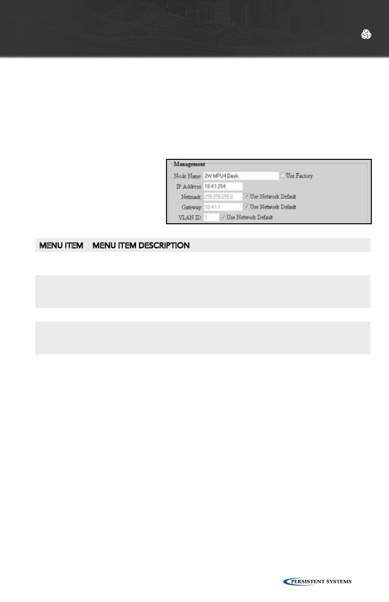
MANAGEMENT SETTINGS
MENU ITEM MENU ITEM DESCRIPTION
Node Name Nodes can be assigned a unique name which is displayed in all of the
management status functions.
IP Address A node IP address can be assigned to allow IP connectivity. The IP address is
generally used for node management functions. An IP address is not required
for actual network operation, only for management and configuration.
Netmask This field defines the netmask for the Web Management Interface.
Gateway This field defines the default gateway if a default gateway is required. The
gateway must be set to an IP address on the same subnet as the IP address
for the node.
VLAN ID
(advanced)
This setting configures this node’s management port VLAN ID. Management
features will ONLY be accessible to the specified VLAN (traffic to/from all
other VLANs is blocked/filtered).

© 2010 - 2015 Persistent Systems, LLC – All Rights Reserved50
WEB MANAGEMENT INTERFACE REFERENCE
RADIO CONFIGURATION
(BASIC RADIO SETTINGS)
MENU ITEM MENU ITEM DESCRIPTION
Name Each radio can be assigned a name to be used in status functions.
MANET (ADVANCED)
MENU ITEM MENU ITEM DESCRIPTION
IP Multicast Rout-
ing
AUTO: Node will prune multicast packets that are not requested (de-
fault, most efficient setting for network).
PULL ALL MULTICAST: Node will accept all multicast packets it hears
on the network. Note: Windows CE/XP computers do not respond
to IGMP Multicast Group Queries sent by Wave Relay nodes. “Pull All
Multicast” should be used in networks with Windows CE/XP computers
to work around this issue.
Root Gateway
Priority
(advanced)
HIGH: Any node in your network directly connected to wired
infrastructure should have priority set to “HIGH.”
MEDIUM: All other non-mobile routers should be set to “MEDIUM.”
LOW: Mobile routers should be set to “LOW.”
DHCP Server
Filter
(advanced)
ALLOW: Device will pass DHCP messages FROM a DHCP server which
is bridged directly by one of its interfaces. Only the devices which are
directly wired to the switch where the DHCP server resides need to be
set to “ALLOW.”
BLOCK: Device will not bridge any DHCP reply packets that it picks
up off of any of its bridged interfaces. By setting all of the nodes in
the network (except the nodes physically connected to the real DHCP
server) to “BLOCK,” you will ensure that users of your system will
always use the correct DHCP server.
SNAP OUI
(advanced)
Controls the Subnetwork Access Protocol Organizationally Unique
Identifier - The factory OUI, 0018A6, is registered to Persistent Systems,
LLC with the IEEE. SNAP OUI is used to identify Wave Relay® packets.
Changing this field allows the user to obscure which protocol is being
used by the system. All nodes must be set to the same value or they will
not communicate.
© 2010 - 2015 Persistent Systems, LLC – All Rights Reserved 51
RADIO CONFIGURATION
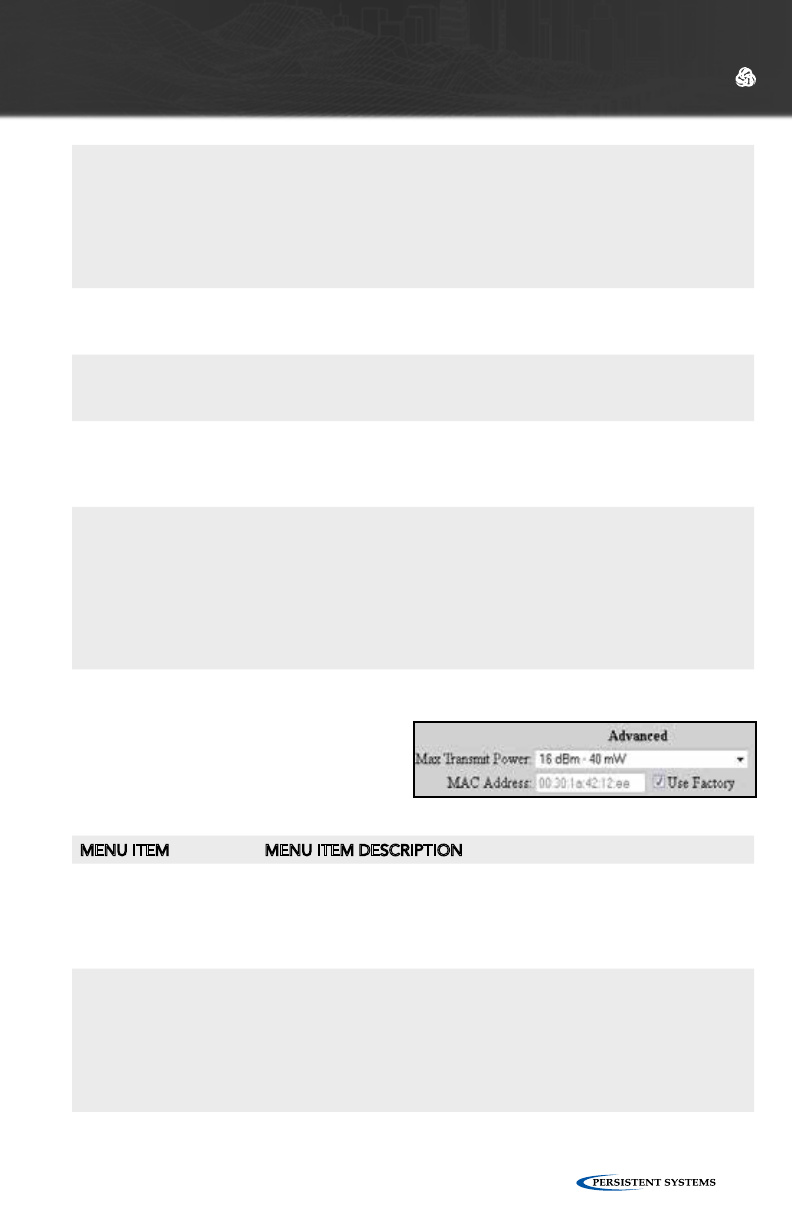
(ADVANCED RADIO SETTINGS)
MENU ITEM MENU ITEM DESCRIPTION
Max Transmit Power
(advanced)
Max Transmit Power will control the radio’s maximum output
power. In general, this configuration is only used to reduce the
output power of a radio for regulatory compliance reasons. The
factory default setting should provide the best communication
performance (highest power) in all other situations.
MAC Address
(advanced)
A custom MAC address may be used for this radio. The entered
value MUST be different from ALL other radio MAC addresses
used in the same network or with the same encryption key. All
radios are factory configured with a globally unique MAC. Since
the MAC address is unencrypted, using a custom MAC that is
periodically changed can help prevent identification and tracking
of the same device across multiple uses.
WEB MANAGEMENT INTERFACE REFERENCE
Frequency Each radio should be a assigned a frequency. Two radios must be set to
the same frequency in order to communicate. If the radio is configured
to use a “Network Default” channel, the radio’s channel assignment can
be managed globally by clicking “Network Configuration” > “Network
Defaults.” Ensure that the frequency is set to match the radio installed
in the unit. A warning will be displayed if the frequency setting does not
match the radio hardware.
Bandwidth Each radio should be assigned a bandwidth. Two radios must be set to
the same bandwidth in order to communicate. Bandwidth should be
increased for shorter distances and decreased for increased distances.
Max Link Dis-
tance
The Max Link Distance should be set to the upper bound of how long
any individual link in the network may need to be. All nodes on the net-
work MUST be set to the same Max Link Distance.
Channel Density The channel density setting controls how aggressively the radios compete
for access to the shared medium. A number of nodes will be displayed in
parentheses after each menu item. Choose the menu item that corre-
sponds to the number of nodes in your network.
Radio Preference Radio Preference instructs the routing protocol to prefer links on a radio
(consider them lower cost than normal). This can be used to help shift traf-
fic towards radios running on certain channels.
None: None is the default factory setting. All links are considered equally.
Medium: Routing protocol is more likely to use this radio to forward
traffic.
High: Routing protocol is significantly more likely to use this radio to
forward traffic.

© 2010 - 2015 Persistent Systems, LLC – All Rights Reserved52
WEB MANAGEMENT INTERFACE REFERENCE
ACCESS POINT SETTINGS
(ADVANCED)
MENU ITEM MENU ITEM DESCRIPTION
802.11 Access Point
(advanced)
2.4GHz and 5.8GHz radios can be configured to function as an
802.11 access point. Standard clients such as laptops with built
in 802.11 cards may access this system. If the AP is disabled, the
ESSID and Beacon Interval configuration options have no effect. For
maximum performance, always disable the 802.11 AP unless it is
required. To use a radio as a 802.11 Access Point, the radio MUST
be set to a valid 802.11 frequency and the channel width MUST be
set to 20MHz.
The following fields are only visible when the 802.11 Access Point is “Enabled.”
Mesh Routing (ad-
vanced)
The Mesh Routing setting enables per radio selection of which
radios participate in the multi-hop mesh routing process. In
a multi-radio node where the user may only want the mesh
running on the backhaul radios, this setting enables the user to
specifically disable the mesh on the client access radios. Be aware
that if a node is only accessible via the mesh and mesh routing is
disabled, connection will be lost to that node.
ESSID (advanced) Sets the name of the network that the access point advertises to
clients.
ESSID Visibility
(advanced)
The ESSID can be configured to be “Visible” or “Hidden.”
Generally, the ESSID is configured to be “Visible” to make it easy
for clients to connect to the access point. For additional security/
privacy the ESSID can be configured as “Hidden.”
AP Security (advanced) Enables or disables 802.11 security on the Access Point - Only
WPA2-PSK (Wi-Fi Protected Access v2 with pre-shared keys) is
supported.
WPA2 Passphrase
(advanced)
Sets a shared passphrase when AP Security is set to WPA2 - The
passphrase should be an ASCII string of length 8-63 characters,
excluding these characters: ‘,”\&/<>
AP Broadcast Rate
(advanced)
Controls the rate at which broadcasts are transmitted from
an 802.11 Access Point - Increasing this rate can significantly
increase network capacity but will reduce the range of client con-
nectivity. If the rate is set too high, client devices will have trouble
receiving broadcast packets from the 802.11 access point.
© 2010 - 2015 Persistent Systems, LLC – All Rights Reserved 53
WEB MANAGEMENT INTERFACE REFERENCE
AP Beacon Interval
(advanced)
The 802.11 access point can send beacons at an interval between
twice and ten times per second.
VLAN ID (advanced) Each 802.11 AP is a VLAN-aware bridge port. Each port is as-
signed a VLAN ID. Untagged frames received by the port are
tagged with the specified VLAN ID. Frames that are sent by the
port which have a VLAN tag matching the specified VLAN ID will
have their tags removed (i.e. they are sent by the port untagged).
VLAN Priority (ad-
vanced)
Specifies the 802.11 priority of the VLAN tag added to untagged
frames received by this port
VLAN Trunking (ad-
vanced)
Controls the filtering of VLAN tagged frames that do NOT match
this port’s VLAN ID - Trunking enabled: ALL non-matching VLAN
tagged frames are passed (no filtering). Trunking disabled: all
non-matching VLAN tagged frames are blocked (filtered).
IP Mcast/Bcast Limit
(advanced)
Defines the maximum bandwidth allowed for IP multicast or
broadcast network traffic received on the given interface and
retransmitted onto the Wave Relay® network - Traffic in excess of
this limit will be dropped. Units are megabits/sec (Mbps). To disable
the limit, set to zero.
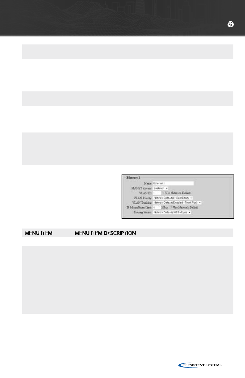
ETHERNET CONFIGURATION
(ADVANCED)
MENU ITEM MENU ITEM DESCRIPTION
Name (advanced) A name can be assigned to each Ethernet interface.
MANET Access
(advanced)
Controls whether MANET traffic is available on a wired Ethernet port
- This setting is useful in cases where the node is physically situated in
an insecure location, and you want to prevent casual passersby from
eavesdropping on the MANET by physically plugging into the Ethernet
port (in this case, be sure to disable access for all wired Ethernet
interfaces on the node). The default setting is “Enabled,” i.e. the
MANET traffic is available on the Ethernet port. Note: the permanent
factory IP address for the node is still available on the Ethernet
port, regardless of this setting. In addition, two Wave Relay® nodes
connected via wired Ethernet can still communicate via encrypted link
regardless of this setting.
VLAN ID
(advanced)
Each Ethernet interface is a VLAN-aware bridge port. Each port
is assigned a VLAN ID. Untagged frames received by the port are
tagged with the specified VLAN ID. Frames that are sent by the port
which have a VLAN tag matching the specified VLAN ID will have their
tags removed (i.e. they are sent by the port untagged).
© 2010 - 2015 Persistent Systems, LLC – All Rights Reserved54
WEB MANAGEMENT INTERFACE REFERENCE
VLAN Priority
(advanced)
Specifies the 802.11 priority of the VLAN tag added to untagged
frames received by this port
VLAN Trunking
(advanced)
Controls the filtering of VLAN tagged frames that do NOT match this
port’s VLAN ID - Trunking enabled: ALL non-matching VLAN tagged
frames are passed (no filtering). Trunking disabled: all non-matching
VLAN tagged frames are blocked (filtered).
IP Mcast/Bcast Limit
(advanced)
Defines the maximum bandwidth allowed for IP multicast or broadcast
network traffic received on the given interface and retransmitted onto
the Wave Relay® network - Traffic in excess of this limit will be dropped.
Units are megabits/sec (Mbps). To disable the limit, set to zero.
Routing Metric
(advanced)
Defines link capacity for the routing protocol - A value lower than
the 100 Mbps default should be used when nodes are connected via
non-switched Ethernet (e.g. a third-party point-to-point wireless link).
The metric allows the routing protocol to make an intelligent decision
whether it is better to route over this Ethernet port or use a faster
alternate route.
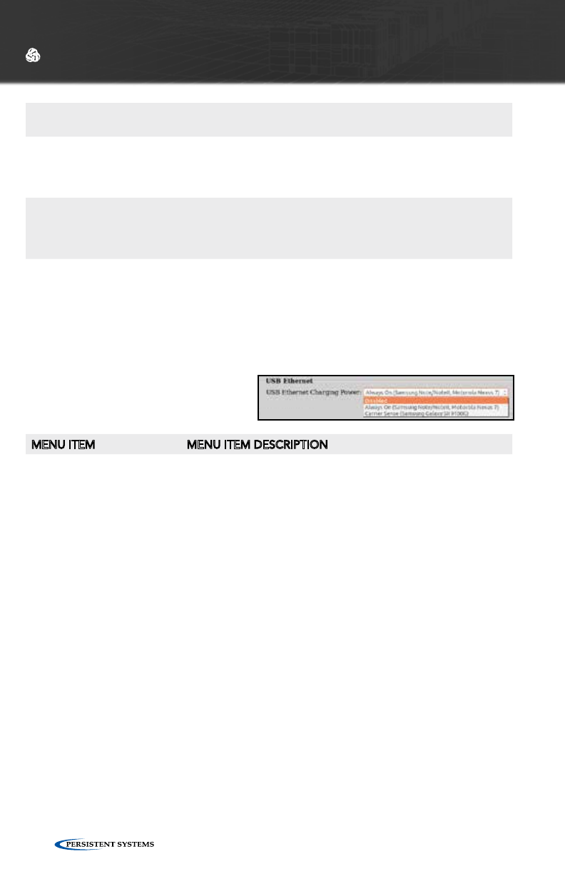
USB ETHERNET (ADVANCED)
MENU ITEM MENU ITEM DESCRIPTION
USB Ethernet Charging
Power
Controls how an EUD connected via a USB Ethernet cable
receives a charge from the node - Should be set to “Always
On” for the Samsung Note/Note II/Note III, Motorola EUDs,
and Nexus 7 and “Carrier Sense” for the Samsung Galaxy SII
9100G.
© 2010 - 2015 Persistent Systems, LLC – All Rights Reserved 55
WEB MANAGEMENT INTERFACE REFERENCE
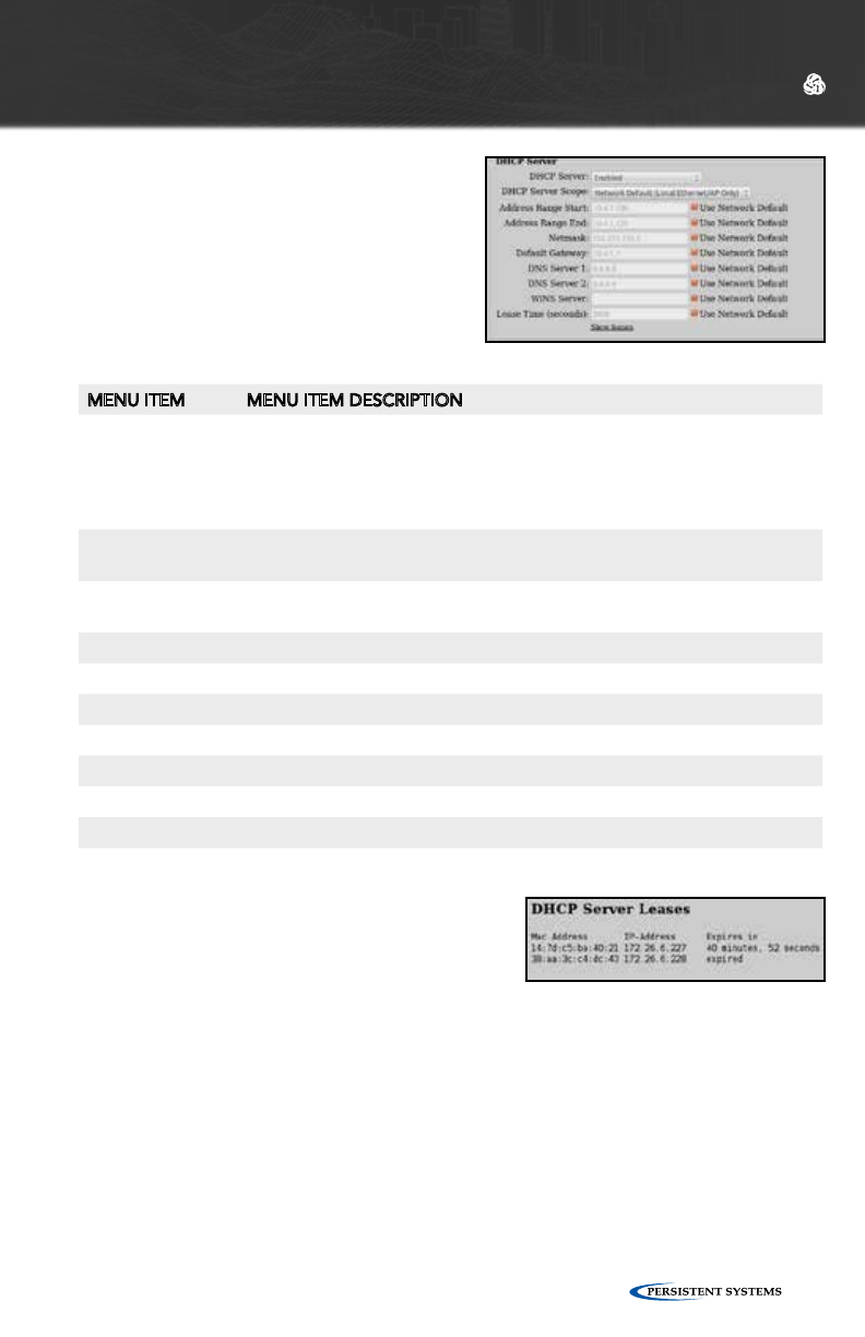
MENU ITEM MENU ITEM DESCRIPTION
DHCP Server
Scope
Selects which DHCP clients the DHCP server serves IP addresses to.
“Local Ethernet/AP Only” serves IP addresses to nodes connected via
Ethernet or a wireless 802.11 Access Point. “Entire Network” serves IP
addresses to all nodes in the network. “Local Ethernet/AP Only” is the
recommended setting.
Address Range
Start
Start of range of IP addresses assigned to DHCP clients
Address Range
End
End of range of IP addresses assigned to DHCP clients
Netmask Netmask assigned to DHCP clients
Default Gateway Gateway assigned to DHCP clients
DNS Server 1 Primary DNS server assigned to DHCP clients
DNS Server 2 Secondary DNS server assigned to DHCP clients
WINS Server WINS server assigned to DHCP clients
Lease Time DHCP lease time (defaults to 1 hour)
Show Leases Displays the MAC and IP address of assigned DHCP leases
DHCP SERVER (ADVANCED)
If enabled, the DHCP server will serve
IP addresses to devices connected
to the node via the wired Ethernet
or wireless 802.11 Access Point
interfaces.
© 2010 - 2015 Persistent Systems, LLC – All Rights Reserved56
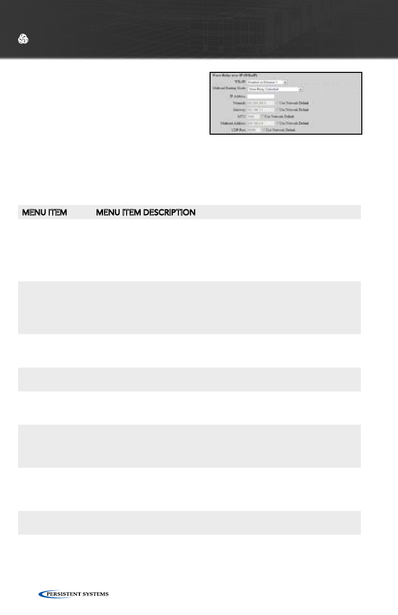
WAVE RELAY® OVER IP (WRoIP)
(ADVANCED)
WRoIP allows the Wave Relay® network to
extend over and seamlessly interact with a
large routed IP network. In order to use this
capability, one or more Wave Relay® nodes
must be setup as WRoIP gateways. A WRoIP
gateway must be directly connected to an appropriately configured IP router.
See Cloud RelayTM Manual
WEB MANAGEMENT INTERFACE REFERENCE
MENU ITEM MENU ITEM DESCRIPTION
WRoIP
(advanced)
WRoIP gateway nodes must have the WRoIP protocol enabled on
the interface directly connected to the IP router. All other nodes
should have the WRoIP protocol disabled. When the WRoIP protocol
is enabled on an interface, the interface will no longer function as a
normal Wave Relay® Ethernet port for connecting Ethernet devices: it
will only work for connecting the IP router.
Multicast Routing
Mode (advanced)
Selects pruning options for multicast traffic:
IP Router Controlled (default): All multicast packets travel to the cloud
network
Wave Relay Controlled: Only subscribed multicast feeds are passed to
the cloud network to reduce network traffic congestion.
IP Address
(advanced)
Defines the IP address of the WRoIP gateway in the IP subnet specific to
the directly connected IP router interface - WRoIP protocol packets will
be sent over the IP network using this IP address.
Netmask
(advanced)
Defines the netmask of the IP subnet specific to the directly connected
IP router interface
Gateway
(advanced)
Defines the IP address of the IP router in the IP subnet specific to the
directly connected IP router interface - WRoIP protocol packets will be
forwarded to this IP address in order to be sent over the IP network.
MTU
(advanced)
Defines the maximum transmissible unit size for the IP network - WRoIP
protocol packets sent over the IP network will be limited to this MTU.
All nodes that communicate over the IP network should be set to the
same value.
Multicast Address
(advanced)
Defines the multicast IP address used by the WRoIP protocol - The next
higher IP multicast address will also be used by the WRoIP protocol. For
example, if 239.255.90.67 is set as the multicast address, both 239.255.90.67
and 239.255.90.68 will be used.
UDP Port
(advanced)
Defines the UDP port used by WRoIP protocol packets
© 2010 - 2015 Persistent Systems, LLC – All Rights Reserved 57
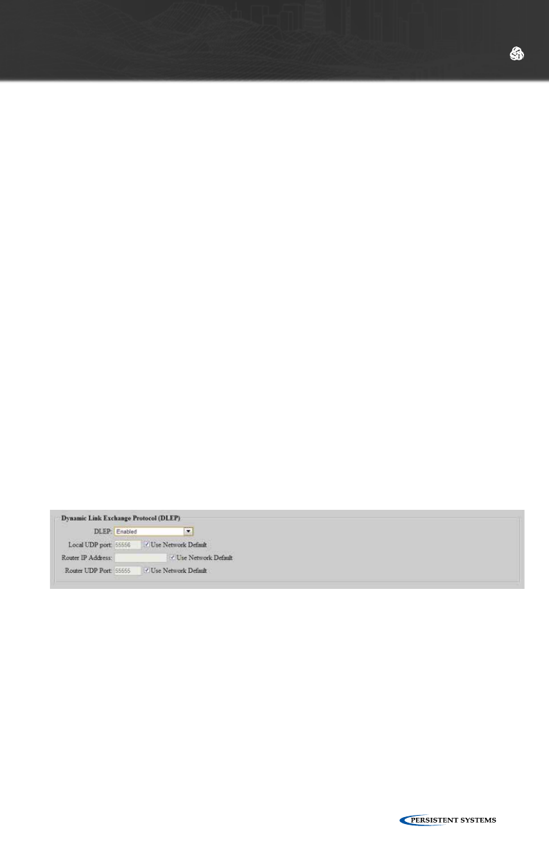
NODE CONFIGURATION FOR DLEP
Dynamic Link Exchange Protocol (DLEP) (advanced):
DLEP is used to transmit characteristics and metrics of the wireless network to a
connected DLEP-capable router such as the Cisco 5915. This feature is available on
all Wave Relay® versions. It supports DLEP Draft 00.
The Wave Relay® MANET operates at Layer 2 of the OSI mode. The DLEP protocol
runs between a router and its attached Wave Relay device, allowing the Wave
Relay® to communicate link characteristics as they change, and convergence events
(acquisition and loss of potential Layer 3 (L3) routing neighbors). Upon receipt of
the signal, the local router may take whatever action it deems appropriate, such
as initiating L3 discovery protocols, and/or issuing HELLO messages to converge
the network on L3. On a continuing, as-needed basis, the Wave Relay devices
utilize DLEP to report any characteristics of the link (bandwidth, latency, etc)to the
L3 router that have changed. DLEP is independent of the link type and topology
supported by the Wave Relay.
•DLEP (advanced): Enable/disable the DLEP subsystem.
•Local UDP Port (advanced): UDP port on the Wave Relay to receive DLEP traffic
from the router.
•Router IP Address (advanced): Network address of the DLEP-capable router.
•Router UDP Port (advanced): UDP port on the DLEP-capable router for receiving
DLEP packets.
WEB MANAGEMENT INTERFACE REFERENCE
© 2010 - 2015 Persistent Systems, LLC – All Rights Reserved58
WEB MANAGEMENT INTERFACE REFERENCE
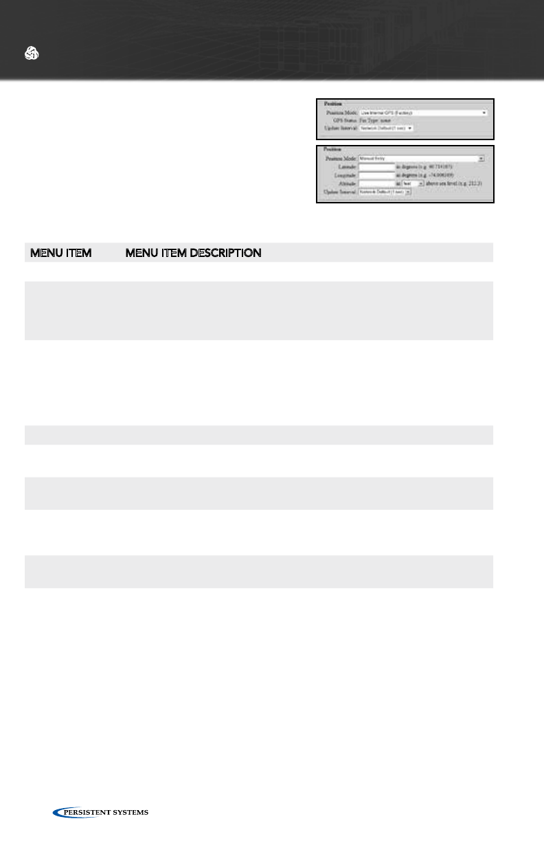
POSITION
The node’s position must be specified in order
to provide data to the visualization, CoT, and
tracking features. The position may be specified
via internal or external GPS, manually, or from an
external feed.
Position Mode:
MENU ITEM MENU ITEM DESCRIPTION
Determines the source of local positioning information
Use Internal GPS Instructs node to receive GPS position information from the optional
integrated GPS module - This control should not be enabled on a device
that does not have an integrated GPS module or if a suitable GPS
antenna with satellite connectivity is not attached.
Use External
GPS
Instructs node to receive GPS position information from an external GPS
device connected via the node’s onboard serial port - A standard NMEA
data stream is supported with the following RS-232 settings: 4800 baud,
8-N-1, no flow control. Higher baud rates are also autodetected. Note that
this option is disabled on Wave Relay® units without serial connectors or
units already using the serial port for other features (e.g. antenna tracking).
Manual Entry Allows manual entry of latitude, longitude, and altitude.
Use External
Feed
Instructs node to receive positioning information over the network via
the external Wave Relay® ‘wr-update-gps’ command
Use ESD Feed Instructs node to receive positioning information over the network via a
ESD (Exploitation Support Data) feed
Use CoT Feed Instructs node to receive positioning information over the network via a
CoT (Cursor on Target) feed. This feature is not available on all firmware
versions.
Use CDF Feed Instructs node to receive positioning information over the network via
Shadow CDF (Common Data Feed)
GPS Status Displays the current status of the GPS (only visible in “Use Internal GPS”
mode)

© 2010 - 2015 Persistent Systems, LLC – All Rights Reserved 59
WEB MANAGEMENT INTERFACE REFERENCE
Latitude Allows the user to manually define the node’s latitude in decimal degrees
(only visible in “Manual Entry” mode)
Longitude Allows the user to manually define the node’s longitude in decimal de-
grees (only visible in “Manual Entry” mode)
Altitude Allows the user to manually define the node’s altitude in feet above GPS
ellipsoid - approximately equal to feet above mean sea level (MSL) (only
visible in “Manual Entry” mode)
External Update
UDP Port
Defines the port number to receive position updates via the external
Wave Relay® ‘wr-update-gps’ command (only visible in “Use External
Feed” mode)
ESD UDP Port Defines the port number to receive position updates via an external ESD
feed (only visible in “Use ESD Feed” mode)
CoT UDP Port Defines the port number to receive position updates via external CoT
feed (only visible in “Use CoT Feed” mode)
CDF UDP Port Defines the port number to receive position updates via an external CDF
feed (only visible in “Use CDF Feed” mode)
Update Interval Controls how often nodes report information back to visualiziation
server with visualization enabled - Smaller values allow finer mobile node
movements in Google™ Earth. Shorter update intervals require more
bandwidth.
© 2010 - 2015 Persistent Systems, LLC – All Rights Reserved60
WEB MANAGEMENT INTERFACE REFERENCE
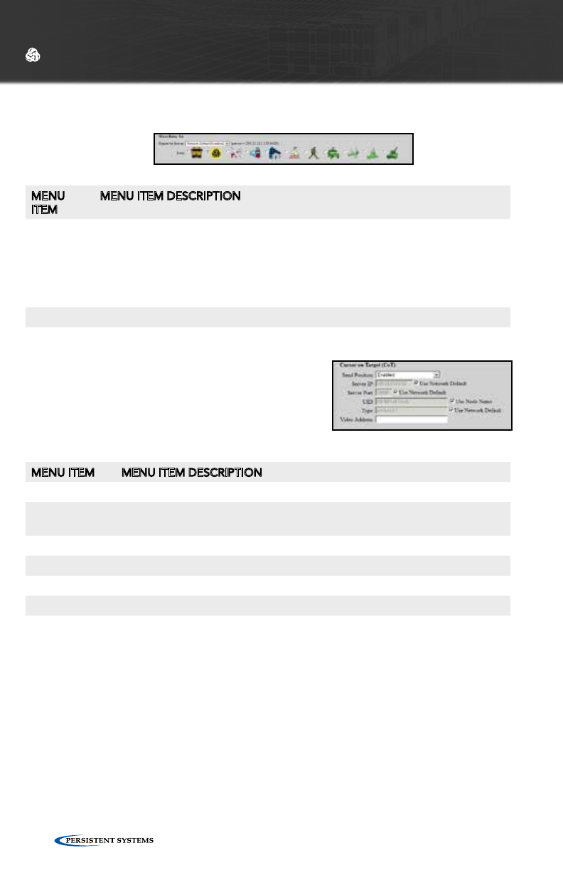
WAVE RELAY® SA (GOOGLE™ EARTH NETWORK VISUALIZATION)
MENU
ITEM
MENU ITEM DESCRIPTION
Report to
Server
Sending visualization updates can be individually enabled or disabled on each
node. Setting “Network Default,” allows visualization to be turned on and off
for the entire network at once via the Network Default configuration. Note
that the selected server IP address is displayed here but is configured as part
of the Network Default configuration. Visualization is also used by the Tracking
Antenna system and should be enabled on nodes that you wish to track.
Icon The user may select an icon that will be used to identify the node in Google™ Earth.
MENU ITEM MENU ITEM DESCRIPTION
Send Position Enables or disables transmission of CoT packets to server
Server IP Defines the IP address of the CoT server - This IP address can be a unicast
or multicast address
Server Port Defines the UDP port of the CoT server
UID Defines the contents of the CoT “uid” attribute
Type Defines the contents of the CoT “type” attribute
Video Address Defines the contents of the CoT “Video Address” attribute
CURSOR ON TARGET (COT) SETTINGS
This feature enables transmission of local position-
ing information to a CoT server on the network.
This feature is not available on all firmware ver-
sions.
SIMPLE SA PACKET GENERATOR (SSPG) (ADVANCED)
These settings exist for backwards compatability with an outdated protocol. See
earlier versions of the manual for more information.
© 2010 - 2015 Persistent Systems, LLC – All Rights Reserved 61
WEB MANAGEMENT INTERFACE REFERENCE
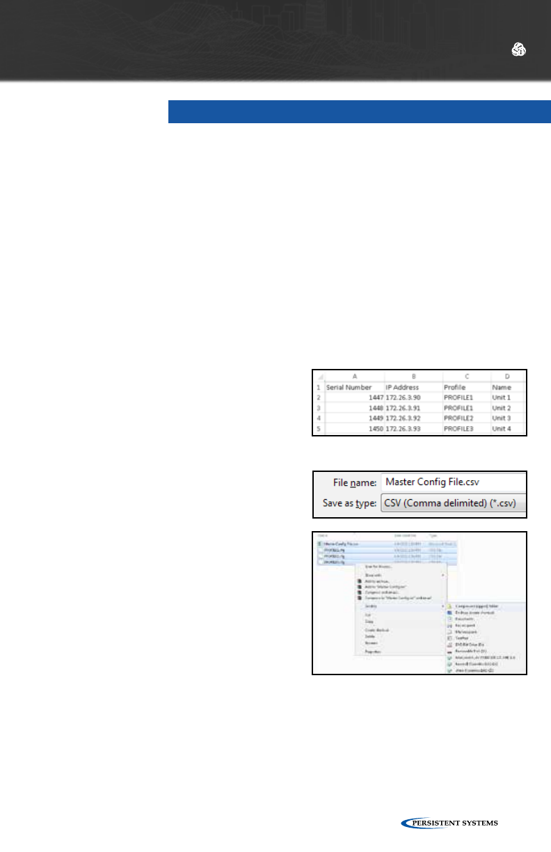
A Master Configuration File allows the user to associate IP addresses, configuration
files, and names with specific nodes.
See RCT Tool Manul
CREATING A MASTER CONFIGURATION FILE
1. Create a temporary directory in an easy to find location with a recognizable
name.
2. Connect a node to the computer and set configuration as desired.
3. Click “Node Configuration” > “Config Management.”
4. Click the “Store” button. A prompt will appear to choose where to save the
configuration file. Save the configuration file to the directory created in Step 1.
5. Repeat steps 2 - 4 for each configuration file that will be uploaded to nodes.
Ensure all configuration file names are
unique.
6. In Microsoft Excel, create a spreadsheet
with 4 columns: Serial Number, IP
address, Profile, and Name.
7. For each node to be managed by the
Master Configuration File, enter that
node’s Serial Number, IP address, the
name of the configuration file saved
in Step 4 to be uploaded to the node,
and the name of the node. Ensure all IP
addresses and names are unique.
8. Click “File” > “Save As” and save
the spreadsheet as a CSV (Comma
delimited) .csv file with a recognizable
name in the directory created in Step1.
9. Create a .zip file containing the CSV file
created in Step 8 and ALL configuration
files created in Step 4.
CONFIGURATION MANAGEMENT
© 2010 - 2015 Persistent Systems, LLC – All Rights Reserved62
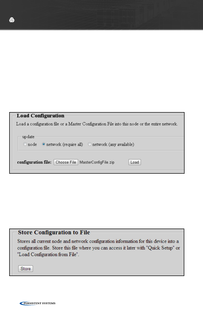
UPLOADING A MASTER CONFIGURATION FILE
1. Ensure all nodes in the Master Configuration File are in the node list.
2. Click “Node Configuration” > “Config Management.”
3. In the Load Configuration menu, select “network (require all)” or “network (any
available)” to upload configuration settings to all nodes in the network. The
“network (require all)” setting will require all nodes in the network be available
for any changes to be applied. If not all nodes are available, no changes will be
applied. The “network (any available)” setting will apply changes to available
nodes only.
4. Click the “Choose File” button to find the the .zip file created in Step 9 above.
5. Click the “Load” button to upload configuration settings to other nodes in the
network.
STORE CONFIGURATION TO FILE
Clicking the “Store” button allows the web browser to download the node’s
configuration settings as an encrypted file. Environment variables, node lists, and
network defaults are stored.
THE CRYPTO KEY IS NOT STORED IN THE CONFIGURATION FILE.
WEB MANAGEMENT INTERFACE REFERENCE
© 2010 - 2015 Persistent Systems, LLC – All Rights Reserved 63
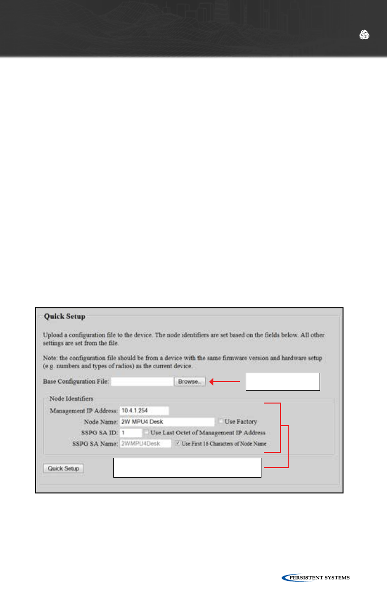
Select the configuration
file to upload.
All settings from the configuration file are written to
the device except Node Identifiers, which are specified
here.
QUICK SETUP
Both “Load Configuration from File” and “Quick Setup” load configuration settings
from a configuration file. The difference between the functions is that “Quick Setup”
loads all the configuration settings from a file (except Node Identifiers), whereas “Load
Configuration from File” loads user-selected configuration categories. Quick Setup
facilitates the configuration of a large number of nodes when the nodes share
identical configuration settings. Note specifically that the only configuration categories
that must be specified when using Quick Setup are Node Identifiers, which include IP
Address, Node Name, and SSPG SA ID.
1. Click “Node Configuration” > “Config Management.” Scroll down to the
“Quick Setup” menu.
2. Click the “Base Configuration File” field or the “Browse...” button and select
the configuration file to load to the device. Note that the configuration file
should be from a device with the same firmware version and hardware setup
(e.g. numbers and types of radios) as the device to which it is being uploaded.
3. Insert the IP Address, Node Name, SSPG SA ID, and SSPG SA Name to be set
to the device.
4. Click the “Quick Setup” button. All settings from the configuration file will be
applied to the device except IP Address, Node Name, SSPG SA ID, and SSPG
SA Name, which will populate from the values specified.
WEB MANAGEMENT INTERFACE REFERENCE
© 2010 - 2015 Persistent Systems, LLC – All Rights Reserved64
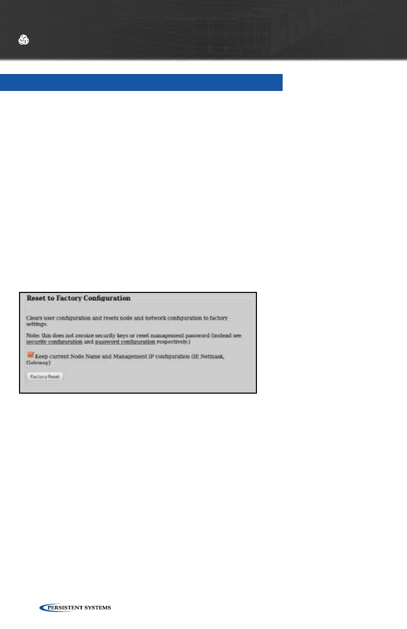
The Web Management Interface contains a “Reset to Factory Configuration” feature
to remove all custom configuration and restore the node to its factory settings.
1. Click “Node Configuration” > “Config Management.” Scroll to the bottom
of the page. Resetting the node to its factory settings will remove all custom
configuration and will reset the IP address to 10.4.1.254.
2. To retain the node name and IP address after the reset, ensure that the box
labelled “Keep node name and IP address” is checked. The node’s Crypto Key
will NOT be zeroized. For instructions on how to zeroize the Crypto Key from
the Security Configuration page, refer to the “Security” section.
3. When you are ready to remove all custom configuration and restore the node to
its factory settings, click the “Reset” button.
WEB MANAGEMENT INTERFACE REFERENCE
RESET TO FACTORY CONFIGURATION
© 2010 - 2015 Persistent Systems, LLC – All Rights Reserved 65
WEB MANAGEMENT INTERFACE REFERENCE
TRACKING ANTENNA CONTROL
For information on setting up the Tracking Antenna Control system hardware, please
refer to the Tracking Antenna Manual.
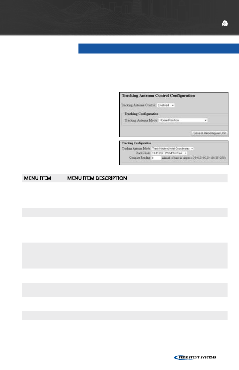
TRACKING CONFIGURATION
MENU ITEM MENU ITEM DESCRIPTION
Tracking Antenna
Mode
Use this menu to choose the source of the coordinates to track or to return
the Pan/Tilt unit to its home position for storage. Possible tracking sources
include another Wave Relay®, a ESD (Exploitation Support Data) feed, a
CoT (Cursor on Target) feed, or CDF (Common Data Feed).
Home Position Returns the Pan/Tilt unit to its home position for storage
Track Node Instructs the node to track another Wave Relay® node position - This
function works by receiving Wave Relay® visualization packets from the
chosen node. Be sure that the tracked node is configured to transmit
Google™ Earth Network Visualization packets.
Track Node w/
Initial Coordi-
nates
This setting is the same as the “Track Node” setting (instructs the node
to track another Wave Relay® node position), but also allows manual
entry of initial coordinates in cases where no position has yet been
received from the tracked Wave Relay® node.
Track via ESD
Feed
Points the antenna based on coordinate data received via an external
ESD feed
Track via CoT
Feed
Points the antenna based on coordinate data received via an external
CoT feed
Track via CDF
Feed
Points the antenna based on coordinate data received via an external
CDF feed
Track Node Selects a Wave Relay® node to track from the Node List
ESD UDP Port Defines the port number to receive coordinate updates via an external ESD
feed
To enable the tracking antenna
control system, go to the “Node
Configuration” tab and click on the
“Tracking Configuration” button.
On the drop down menu, select
“Enabled” next to the Tracking
Antenna Control option.
© 2010 - 2015 Persistent Systems, LLC – All Rights Reserved66
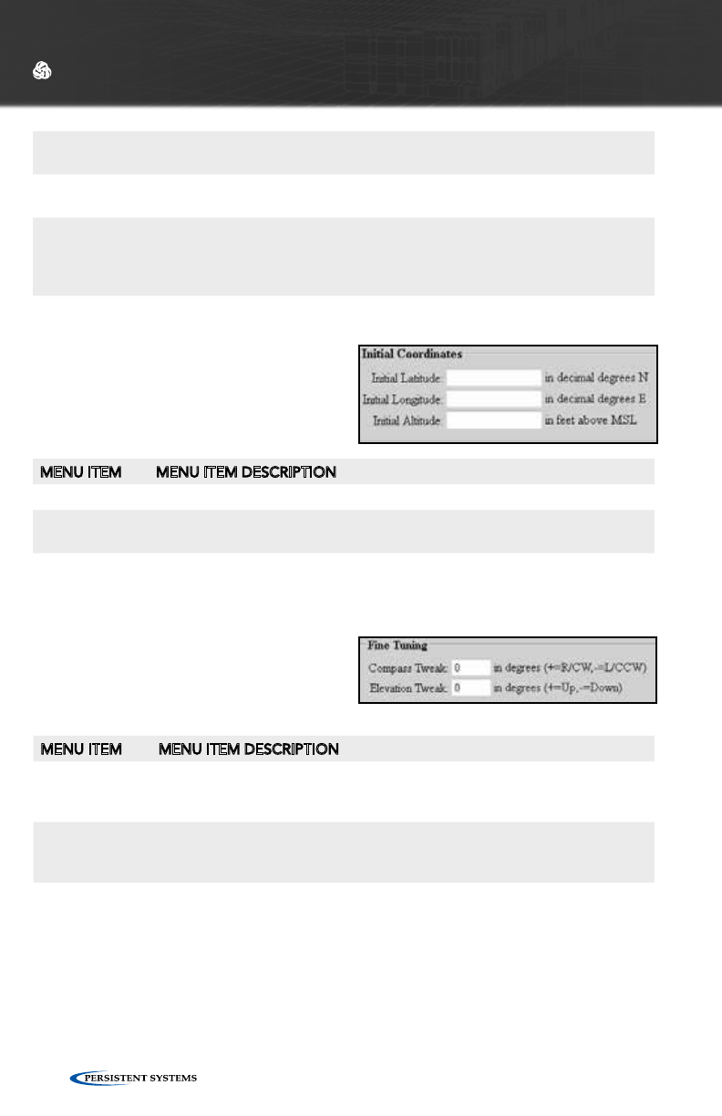
INITIAL COORDINATE SETTINGS
These fields allow specification of the
initial antenna target location in cases
where coordinates have not yet been
received from the tracked node.
WEB MANAGEMENT INTERFACE REFERENCE
MENU ITEM MENU ITEM DESCRIPTION
Initial Latitude Sets the tracked node’s initial latitude in decimal degrees
Initial Longi-
tude
Sets the tracked node’s initial longitude in decimal degrees
Initial Altitude Sets the tracked node’s initial altitude in feet above GPS ellipsoid, which is
approximately equal to feet above mean sea level (MSL)
FINE TUNING SETTINGS
MENU ITEM MENU ITEM DESCRIPTION
Compass
Tweak
Defines the heading correction factor for tracking, specified in decimal
degrees - Use a positive number for right/clockwise correction and a
negative number for left/counterclockwise correction.
Elevation
Tweak
Defines the elevation correction factor for tracking, specified in decimal
degrees - Use a positive number for upward correction and a negative
number for downward correction.
CoT UDP Port Defines the port number to receive coordinate updates via an external
CoT feed
CDF UDP Port Defines the port number to receive coordinate updates via an external
CDF feed
Compass Read-
ing
Specifies the heading of the Pan/Tilt unit - The heading is defined as the
compass reading taken when standing behind the Pan/Tilt unit while fac-
ing the large circular electrical connector. For more information, see the
compass reading step of the setup procedure.
© 2010 - 2015 Persistent Systems, LLC – All Rights Reserved 67
WEB MANAGEMENT INTERFACE REFERENCE
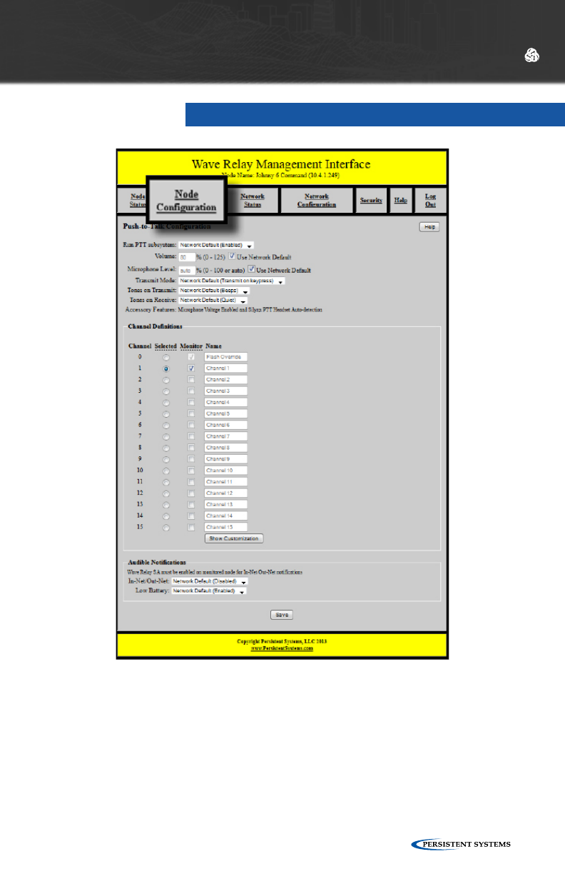
PUSH-TO-TALK (PTT)
Push-to-Talk (PTT) voice is supported on all Wave Relay® nodes. By default, Wave
Relay® supports single-channel PTT voice on a specified multicast IP address and port.
You can “switch channels” by specifying an alternate IP address or port. Users can talk
or listen (but cannot do both simultaneously). Transmissions from an individual user
are broadcast to all other users on the network. Only one person can talk at a time.
If a user tries to talk when another user is transmitting, a busy tone will be heard.
To configure Push-to-Talk settings, click “Node Configuration” > “PTT
Configuration.”
© 2010 - 2015 Persistent Systems, LLC – All Rights Reserved68
WEB MANAGEMENT INTERFACE REFERENCE
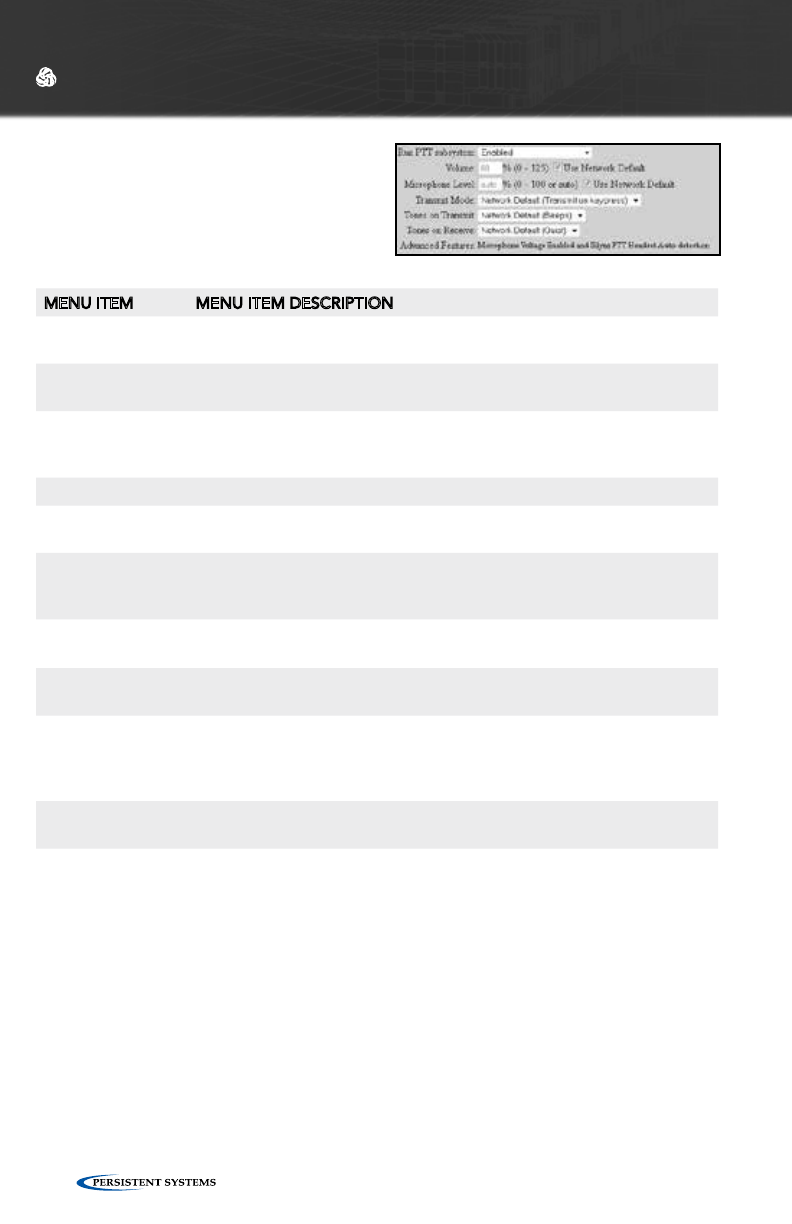
PUSH-TO-TALK CONFIGURATION
MENU ITEM MENU ITEM DESCRIPTION
Run PTT subsys-
tem
Enables or disables push-to-talk voice
Volume Defines the default earpiece volume for headsets - Valid values are 0
through 125 (Values above 100 are digitally amplified)
Microphone Level Defines the default microphone level for headsets - Valid values are 0
through 100 or “auto.” The “auto” configuration uses automatic gain
control for microphone input and is recommended for most users.
Transmit Mode
Transmit on
keypress
Audio is transmitted only when the PTT button is pressed on the
headset.
Transmit continu-
ously
Audio is continuously transmitted. Other nodes may monitor the
channel only. Selected Channel audio transmissions will interrupt
monitored continuously transmitted audio.
Tones on Transmit Enables or disables an audible checktone (either Beeps or Verbal) at
the beginning of each transmitted message
Tones on Receive Enables or disables an audible checktone (either Beeps or Verbal) at
the beginning of each received message
Advanced Fea-
tures
If advanced features are able to be configured, a drop down menu will
appear. If advanced features are not able to be configured, a string
will appear displaying the current configuration. Available features vary
among Wave Relay® hardware versions.
Silynx PTT Head-
set
Enables the serial port on the node (Silynx PTT Headsets require this
setting be enabled)
Microphone
Voltage
Enables +5V power supply voltage on the center pin of the 6-pin head-
set connector (required for some headsets)
© 2010 - 2015 Persistent Systems, LLC – All Rights Reserved 69
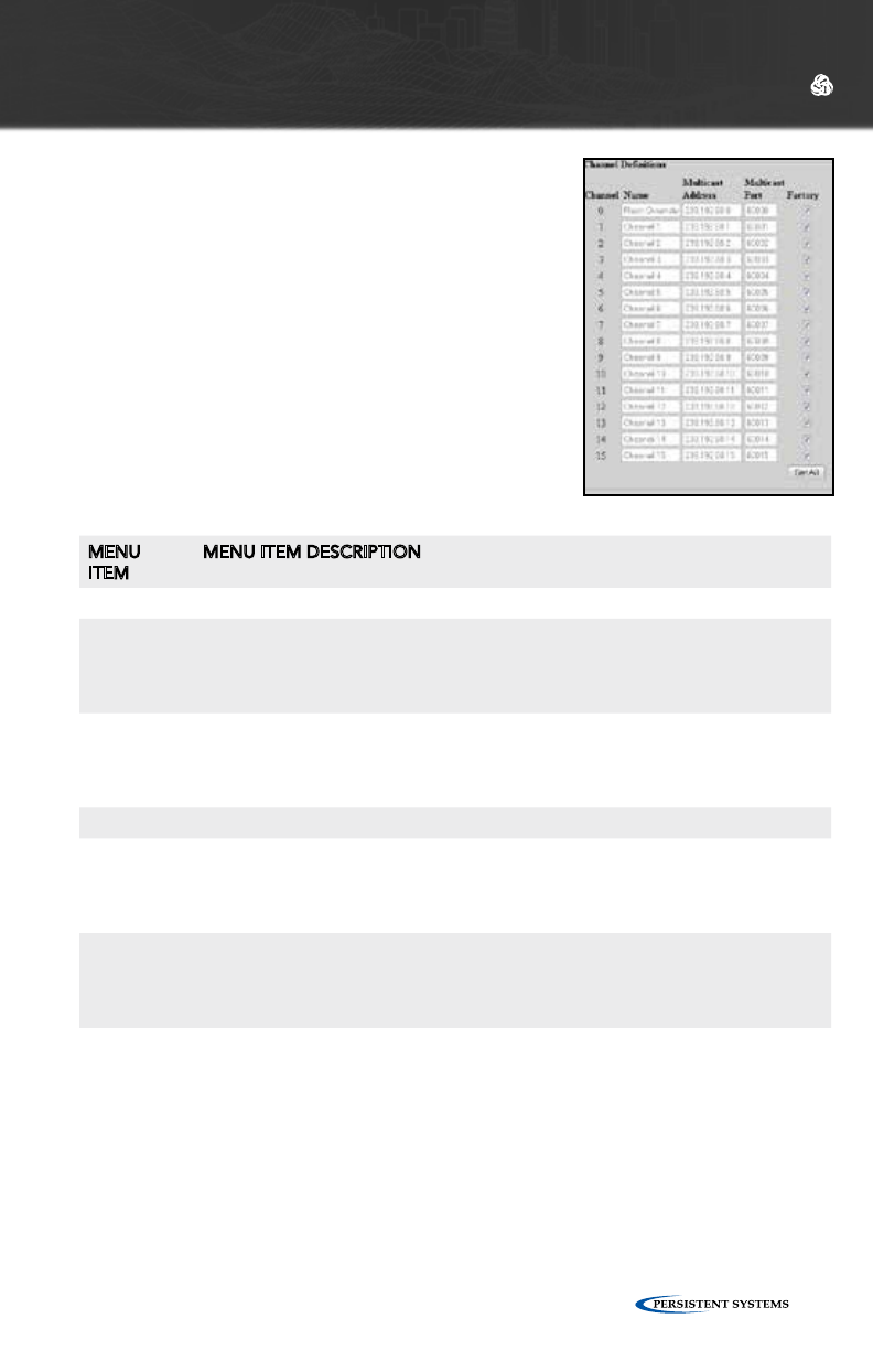
CHANNEL DEFINITIONS
The Wave Relay® Network has 16 channels numbered
0 through 15. Channel 0 is the Flash Override
Channel and has priority over channels 1-15. The
Flash Override Channel will always be enabled and
is capable of both receiving and transmitting audio.
Channels 1-15 are normal audio channels. Audio
channels 1-15 may be configured to be either Selected
Channels or Monitored Channels. Flash Override
Channel audio will interrupt both Selected Channel
audio and Monitored Channel audio. Each channel is
defined by a Multicast Address and a Multicast Port.
To display the Multicast Address and Multicast Port
fields, click the “Show Customization” button. After
Channel Definition settings have been configured, click
the “Set All” button.
WEB MANAGEMENT INTERFACE REFERENCE
MENU
ITEM
MENU ITEM DESCRIPTION
Channel Displays the channel number to be configured
Selected A Selected Channel is capable of both receiving and transmitting PTT audio.
Selected Channel audio will NOT interrupt Flash Override Channel audio.
Selected Channel audio will interrupt Monitor Channel audio. A user MUST
choose a Selected Channel from channels 1-15.
Monitor A Monitored Channel is only capable of receiving audio transmissions. Both
Flash Override Channel audio and Selected Channel audio will interrupt
Monitored Channel audio. A user may select none to multiple channels to be
Monitored Channels.
Name Defines the text name of the channel
Multicast
Address
Defines the Multicast Address for the channel (Valid values are within the
range of 224.0.0.0 through 239.255.255.255) - Note that each talk group must
have a unique multicast address and port. This field is only visible if the “Show
Customization” button has been clicked
Multicast
Port
Defines the Multicast UDP port for audio traffic (Valid values are within the
range of 1 through 65534) - Note that each talk group must have a unique
multicast address and port. This field is only visible if the “Show Customiza-
tion” button has been clicked.
FLASH OVERRIDE
Flash Override is a new feature which allows audio to be sent to all nodes even if
those nodes have selected a different audio channel.
• A flash override transmission is triggered by a “tap-tap-hold” of the PTT
button(button is pressed and released twice quickly in succession immediately
preceding the normal hold for the duration of the transmission.)
• The user will hear a unique “triple” tone on TX and RX to indicate a flash over-
ride.

© 2010 - 2015 Persistent Systems, LLC – All Rights Reserved70
WEB MANAGEMENT INTERFACE REFERENCE
AUDIBLE NOTIFICATIONS
MENU ITEM MENU ITEM DESCRIPTION
Low Battery Enables or disables audible notification when the battery is depleted to
5% (notification will occur every 5 minutes)
In-Net/Out-Net Enables or disables an audible notification when a chosen node enters or
leaves the network
Node to Monitor Selects a node to monitor for In-Net/Out-Net audible notifications from
the node list (only visible when In-Net/Out-Net Audible Notifications are
enabled)
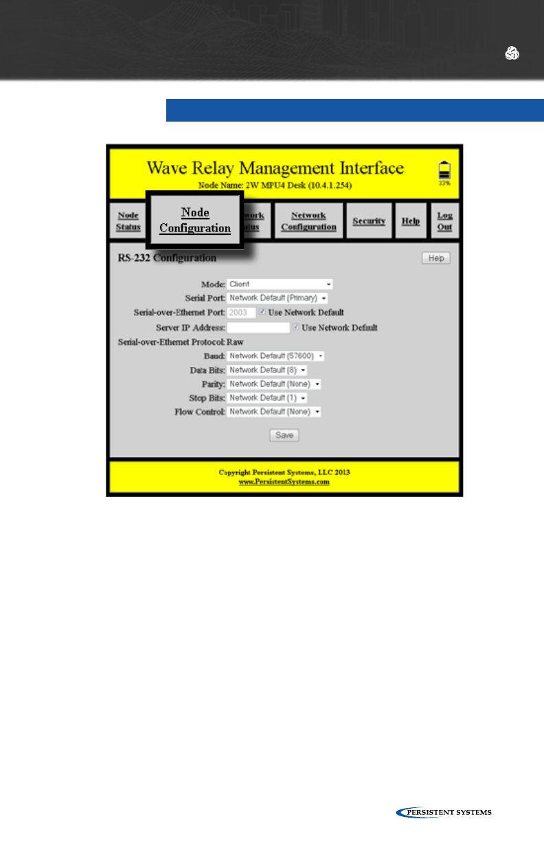
© 2010 - 2015 Persistent Systems, LLC – All Rights Reserved 71
RS-232
WEB MANAGEMENT INTERFACE REFERENCE
The RS-232 serial-over-Ethernet feature can be used for remote control of a distant
serial device via the Wave Relay® network. A typical application is for a local PC to
control a distant pan/tilt camera via a serial link. If the PC and camera cannot be
colocated, then two Wave Relay® devices can be used to connect them (similar to an
old-fashioned modem-to-modem link). Thus, the serial port on the local PC can be
hardwired to a local Wave Relay® device and the serial port on the distant camera
can be hardwired to a distant Wave Relay® device. Communication between the two
devices is then relayed via the Wave Relay® network. This is called “serial-to-serial
mode.”
Alternatively, the PC can run emulation software that allows it to create a local
virtual COM port that is configured to communicate directly with a distant network-
enabled serial port (e.g. as described in RFC 2217). Thus, the distant camera is
hardwired to a distant Wave Relay® device and the local PC can then connect
directly to the distant device via Ethernet. This is called “virtual-to-serial mode.”
To access RS-232 configuration settings, click “Node Configuration” > “RS-232
Configuration.”
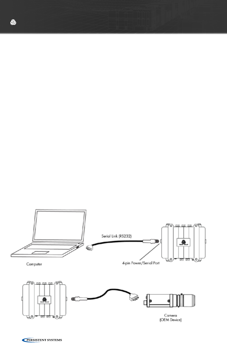
© 2010 - 2015 Persistent Systems, LLC – All Rights Reserved72
CONFIGURING SERIAL-TO-SERIAL MODE
1. Connect the serial device to be controlled (e.g. pan/tilt unit) to the serial port on
the distant Wave Relay® device. Configure the RS-232 Configuration Mode on
the distant Wave Relay device to “Server” and set the Serial-over-Ethernet Port
as desired. Set the Serial-over-Ethernet Protocol to “Raw.” Set the serial port
parameters (Baud, Data Bits, Parity, Stop Bits, Flow Control) to match those of the
connected serial device (factory defaults for the Wave Relay® device are 57600
baud, 8 data bits, no parity, 1 stop bit, no flow control). Click “Save” to store the
settings.
2. Connect the local serial device (e.g. PC) to the serial port on the local Wave
Relay® device. Set the RS-232 Configuration Mode on the local Wave Relay®
device to “Client,” and set the Server IP Address and Serial-over-Ethernet Port
to be those of the distant Wave Relay® device as configured in Step 1 above.
Also set the serial parameters (Baud, Data Bits, Parity, Stop Bits, Flow Control)
to match those of your local serial device. Click “Save” to store the settings.
CONFIGURING VIRTUAL-TO-SERIAL MODE
1. Connect and configure the serial device to be controlled (e.g. pan/tilt unit) as
per Step 1 above for Configuring Serial-to-Serial mode. Set the Serial-over-
Ethernet Protocol to whichever protocol is supported by your virtual client
(“Raw” or “Telnet RFC 2217”).
2. Install Virtual COM port software on the local PC (Eltima Serial to Ethernet
Connector v5.0 for Windows has been tested and is known to work). Configure
the virtual COM port in your software to connect to the distant serial port via
the address/port as configured in Step 1.
WEB MANAGEMENT INTERFACE REFERENCE
SERIAL-TO-SERIAL MODE
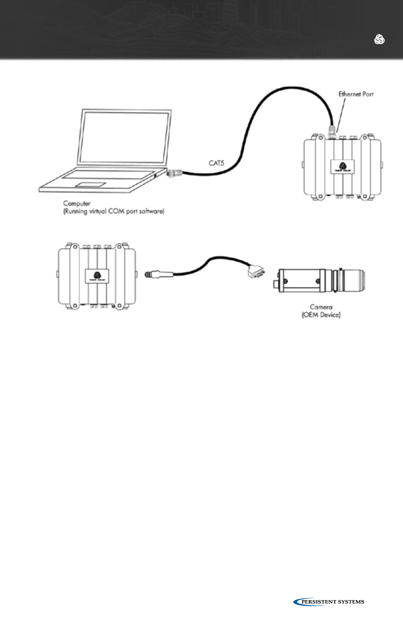
© 2010 - 2015 Persistent Systems, LLC – All Rights Reserved 73
WEB MANAGEMENT INTERFACE REFERENCE
VIRTUAL-TO-SERIAL MODE
CONFIRMING SERIAL CONNECTIVITY
Once you have configured the server and client as described above, the network
connection status is displayed on the “Current Status” line. Statistics are displayed for
transmitted and received bytes to/from the attached serial device, which can be used
to debug the connection to your serial hardware. For example, if the “tx” byte count
increases but the “rx” byte count remains zero, bytes are being sent out on the Wave
Relay® serial port but no reply is being received (possibly due to reversed transmit
and receive wires in your cable). To update the status and statistics, click the “Refresh”
button.
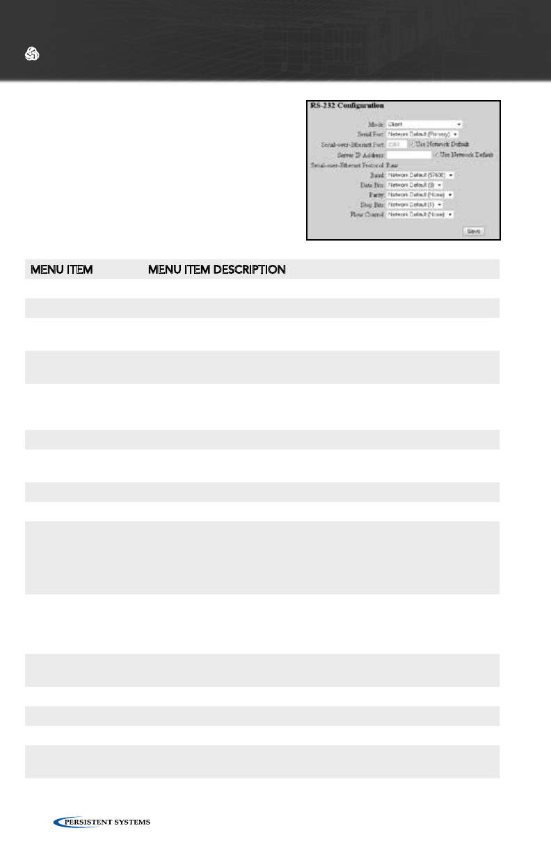
© 2010 - 2015 Persistent Systems, LLC – All Rights Reserved74
WEB MANAGEMENT INTERFACE REFERENCE
MENU ITEM MENU ITEM DESCRIPTION
Mode
Disabled The serial-over-Ethernet feature is turned off.
Server Use this mode when the device to be controlled (e.g. pan/tilt unit) is
connected to a Wave Relay® device serial port.
Client Use this mode when a controller (e.g. PC) is connected to a Wave
Relay® device serial port.
Echo Mode Instructs the serial port to retransmit any received serial data out
on its transmit pin (useful for debugging serial connections in cases
where Rx/Tx pins might be accidentally reversed in the cable)
Serial Port Selects the primary or secondary RS-232 port on the Wave Relay®.
Serial-over-Ethernet
TCP Port
Defines the TCP port for serial-over-Ethernet traffic
Server IP Address Dfines the default IP address of the serial-over-Ethernet server
Serial-over-Ethernet Protocol
Raw Serial messages are encapsulated into packets and are transmitted
unaltered over the network. This setting requires that the RS-
232 parameters (baud, parity, etc.) be set correctly at both ends.
This setting is typically used in serial-to-serial mode, e.g. when a
hardware serial controller is used to control a remote serial device.
Telnet - RFC2217 Serial messages are encapsulated into packets as per RFC2217,
and baud settings are automatically controlled by the protocol. This
setting is typically used in serial-to-virtual mode, e.g. when a PC with
virtual COM ports is used to control a remote serial device.
Baud Valid settings are 300, 1200, 2400, 4800, 9600, 19200, 38400, 57600,
or 115200.
Data Bits Valid settings are 7 or 8 bits.
Parity Valid settings are None, Even, or Odd.
Stop Bits Valid settings are 1 or 2 bits.
Flow Control Valid choices are XON/XOFF (a.k.a. software flow control) or None.
Note that RTS/CTS (a.k.a. hardware flow control) is not supported.
RS-232 CONFIGURATION
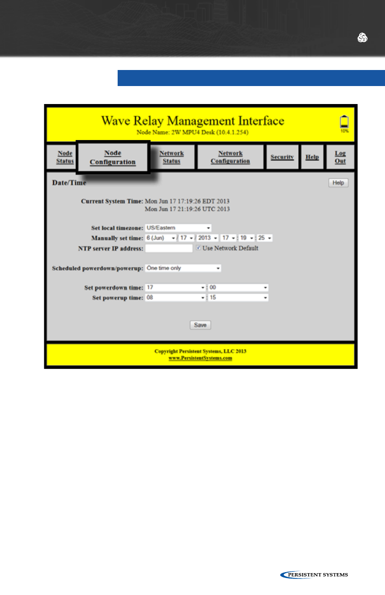
© 2010 - 2015 Persistent Systems, LLC – All Rights Reserved 75
WEB MANAGEMENT INTERFACE REFERENCE
DATE/TIME
When possible, Wave Relay® will obtain the current date and time from its internal
GPS hardware. However, in cases where the GPS is unlocked (or absent), you may
alternatively specify an NTP server or manually set the current date and time. You
may also set the local time zone. The default time zone is UTC (a.k.a. GMT or Zulu
time). Note that some Wave Relay® device models do not contain a clock, and thus
these settings may be unavailable.
Wave Relay® also supports a sleep feature that allows scheduling remote unit
power down and power up in order to conserve battery life and/or maintain radio
silence. Sleep can be performed as a one-time power cycle or can be scheduled for
repetitive daily or hourly operation. The sleep feature is not available on all Wave
Relay® device models.
To access Date/Time Configuration, click “Node Configuration” > “Date/Time.”

© 2010 - 2015 Persistent Systems, LLC – All Rights Reserved76
WEB MANAGEMENT INTERFACE REFERENCE
MENU ITEM MENU ITEM DESCRIPTION
Current System Time Displays the current system time (in both UTC and current time
zone if not UTC)
Set local timezone Sets the local time zone as ±12 hours from UTC (settings also
include select US and other global time zones)
Manually set time Manually sets the current local time
NTP Server Address Defines the address, if available, of the NTP (Network Time Proto-
col) server for automatic clock synchronization
Scheduled powerdown/powerup
One time only Instructs nodes to perform a one-time power down and power
up at specified times as set in the Set powerdown time and Set
powerup time fields
Daily Instructs nodes to perform a daily powerdown and powerup as
specified in the Set powerdown time and Set powerup time fields
Twice daily Instructs nodes to perform a twice-daily powerdown and powerup
as specified in the Set powerdown time, Set powerup time, Set
2nd powerdown time, and Set 2nd powerup time fields
Hourly Instructs nodes to perform hourly powerdowns and powerups as
specified in the Set powerdown time and Set powerup time fields
- powerdown and powerup times are specified as minutes past
the hour (00 through 59)
Set powerdown time Selects the hour and minute (in local time zone) for unit power-
down - If the powerdown/power up frequency is set to “Hourly,”
then you may only set minutes past the hour.
Set powerup time Selects the hour and minute (in local time zone) for unit powerup -
If the powerdown/powerup frequency is set to “Hourly,” then you
may only set minutes past the hour. If the powerup time is before
the powerdown time, then the powerup happens the next day (or
hour).
Set 2nd powerdown
time
Selects the hour and minute (in local time zone) for second daily power-
down - This setting is valid only when power down/power up frequency is
set to “Twice Daily.”
Set 2nd powerup time Selects the hour and minute (in local time zone) for second daily powerup
- If the powerup time is before the powerdown time, then the powerup
happens the next day (or hour). This setting is valid only when powerdown/
powerup frequency is set to “Twice Daily.”
DATE/TIME SETTINGS
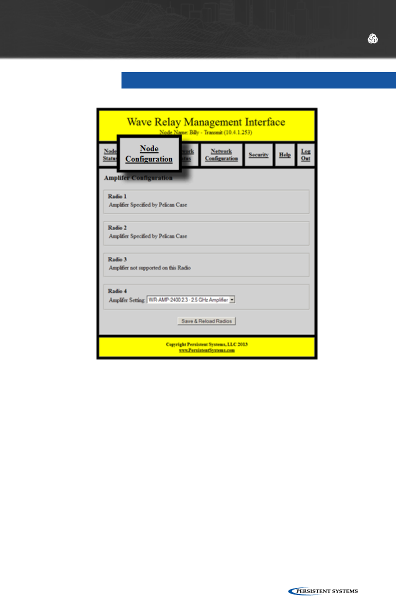
© 2010 - 2015 Persistent Systems, LLC – All Rights Reserved 77
WEB MANAGEMENT INTERFACE REFERENCE
Any Wave Relay® device (MPU4, MPU3 Single, MPU3 Dual, and Quad Radio Router)
may be configured for use with an amplifier. To access Amplifier Configuration
settings, select the “Node Configuration” tab, then click the “Amplifier
Configuration” button. The page will display separate sections for each radio so that
the amplifier settings for each radio may be configured separately.
Depending on the radios installed in the node, several different options will appear.
If the radio installed in the node does not support the use of an amplifier, the
section on the page corresponding to that radio will display the message “Amplifier
not supported on this Radio.”
If the radio installed in the node does support the use of an amplifier, a drop-down
menu titled “Amplifier Setting” will appear. On the drop-down menu, select the
amplifier setting that matches the amplifier being used with the radio.
AMPLIFIER CONFIGURATION

© 2010 - 2015 Persistent Systems, LLC – All Rights Reserved78
VALID AMPLIFIER SETTINGS ARE:
• WR-AMP-0900 900 MHz Amplifier
• WR-AMP-1370 1.3 GHz Amplifier
• WR-AMP-2400 2.3 - 2.5 GHz Amplifier
When the Amplifier Configuration page for a QAMP device is accessed from the
Web Management Interface, the sections for some radios may display the message
“Amplifier Specified by Pelican Case.” The amplifier settings for these radios have
already been configured.
WARNING: WAVE RELAY® AMPLIFIERS REQUIRE REGULATED 28V
DC POWER SUPPLY (DEVIATIONS WILL CAUSE DEGRADATION IN
PERFORMANCE).
WEB MANAGEMENT INTERFACE REFERENCE
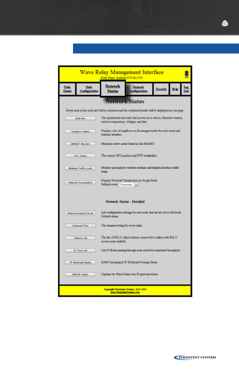
© 2010 - 2015 Persistent Systems, LLC – All Rights Reserved 79
WEB MANAGEMENT INTERFACE REFERENCE
NETWORK STATUS
The “Network Status” tab in the Web Management Interface displays information
about every node in the node list. Each time a network status feature is used, all
nodes in the node list will attempt to be contacted and the combined results will
be displayed on one page. This feature is useful for managing a network without
having to individually connect to each node. Refer to the “Node Status” section for
more detailed information about a specific feature.
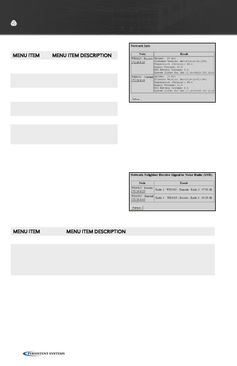
© 2010 - 2015 Persistent Systems, LLC – All Rights Reserved80
WEB MANAGEMENT INTERFACE REFERENCE
MENU ITEM MENU ITEM DESCRIPTION
Node Node name and IP address
of each node in the network
Uptime Operating time since last
node power on or reboot
Firmware Ver-
sion
Firmware version on node
Temperature Temperature (in celsius) of
node
Supply Voltage Voltage supplied to node
RCT Battery
Voltage
Voltage of real-time-clock
keep-alive battery. 3 year
shelf life when not powered
System Clock Current system time of node
UNIT INFO
NEIGHBOR STATUS
The Neighbor Status page displays a list of all
neighboring nodes in the network.
MENU ITEM MENU ITEM DESCRIPTION
Node Name and IP address of node
Result • Interface on managed node used
• Name of each neighbor node
• Interface on the neighbor node used
• Receive Signal to Noise Ratio of each connection to each
Interface on each neighbor node
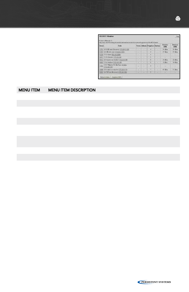
© 2010 - 2015 Persistent Systems, LLC – All Rights Reserved 81
WEB MANAGEMENT INTERFACE REFERENCE
MENU ITEM MENU ITEM DESCRIPTION
Serial Serial number of all nodes active on MANET network
Node Node name and IP address of each neighbor node
Vector Distance and direction from local node to remote node (Only valid if both
nodes have a GPS fix or location)
Altitude Altitude (above sea level) of each node in MANET network
Neighbors Number of neighbor nodes (includes neighbors transmitting over the air
and via Ethernet)
Battery Battery percentage remaining (Only valid when using a MPU4 with
compatible smart battery)
Receive SNR Signal-to-Noise Ratio at which local node hears remote node
Reverse SNR Signal-to-Noise Ratio at which the local node is heard by the remote node
MANET MONITOR
MANET Monitor displays informa-
tion about active nodes heard on the
MANET.
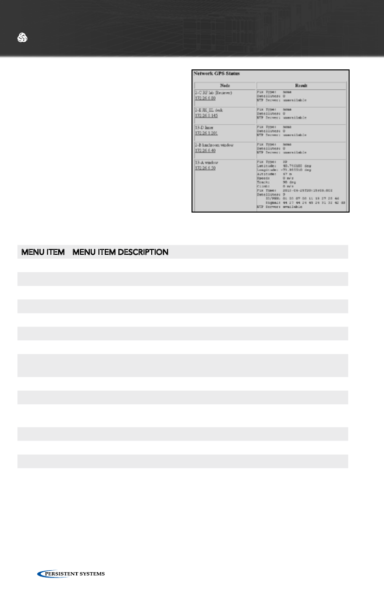
© 2010 - 2015 Persistent Systems, LLC – All Rights Reserved82
GPS STATUS
MENU ITEM MENU ITEM DESCRIPTION
Node Name and IP address of each node
Result
Fix Type How node is connected (3D, 2D, or none)
Latitude Latitude of current node
Longitude Longitude of current node
Altitude Altitude above sea level of current node
Speed Speed of node (m/s) in the horizontal plane
Track Path of travel with respect to the Earth expressed in degrees - 000 degrees is
North (angle increases clockwise through 360 degrees)
Climb Speed of node (m/s) in the vertical plane
Fix Time When node obtained a satellite fix
Number of
satellites
Number of satellites node is connected to
ID/PRN ID/PRN of each satellite node is connected to
Signal Strength of the connection between node and each satellite
NTP Server Status of the NTP server (available or unavailable)
WEB MANAGEMENT INTERFACE REFERENCE
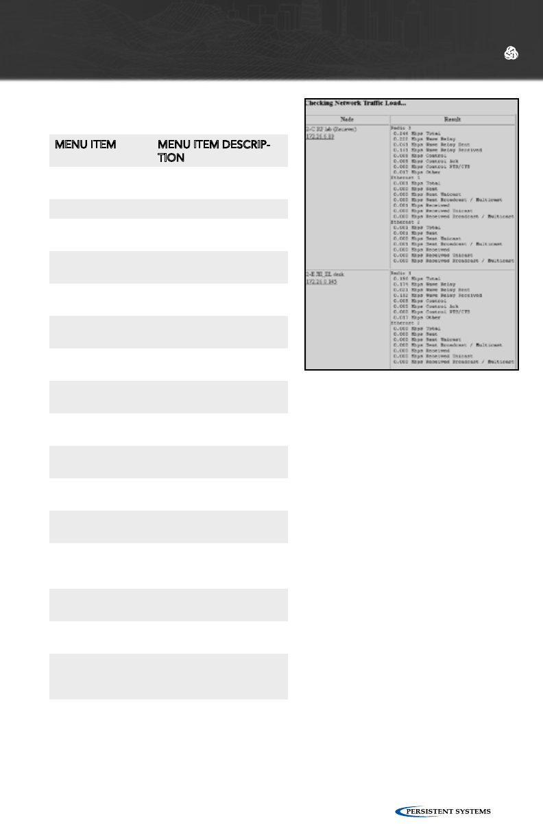
© 2010 - 2015 Persistent Systems, LLC – All Rights Reserved 83
WEB MANAGEMENT INTERFACE REFERENCE
MENU ITEM MENU ITEM DESCRIP-
TION
Node Name and IP address of
each node
Result
Mbps Total Total Mbps used on this
interface
Mbps Wave
Relay®
Total Mbps used by
Wave Relay®
Mbps Wave Re-
lay® Sent
Mbps used by Wave
Relay® to send
Mbps Wave
Relay® Received
Mbps used by Wave
Relay® to receive
Mbps Control Total Mbps used for
control functions
Mbps Control Ack Mbps used to control
ACK
Mbps Control
RTS/CTS
Mbps used to control
RTS/CTS
Mbps Other Mbps used for other
functions
Mbps Sent Total Mbps used for all
transmissions
Mbps Sent Unicast Mbps used for Unicast
transmissions
Mbps Sent Broad-
cast/Multicast
Mbps used for
Broadcast/Multicast
transmissions
Mbps Received Total Mbps used to
receive all transmissions
Mbps Received
Unicast
Mbps used to receive
Unicast transmissions
Mbps Received
Broadcast/
Multicast
Mbps used to receive
Broadcast/Multicast
transmissions
NETWORK TRAFFIC LOAD
NETWORK VISUALIZATION
This feature displays situational
awareness GPS mapping for all
network nodes in Google™ Earth. The
drop down menu selects how often
Google™ Earth will refresh its data
from the visualization server. To access
Network Visualization:
1. Click the “Network Visualization”
button. The browser will attempt
to open a file called “node-
monitor.kml.” This file contains
geographic data to be displayed
in Google™ Earth.
2. Either open the file directly from
the pop-up dialogue box or save
the file to the computer and open
it separately.
The management computer must
have Google™ Earth installed for this
feature to work.
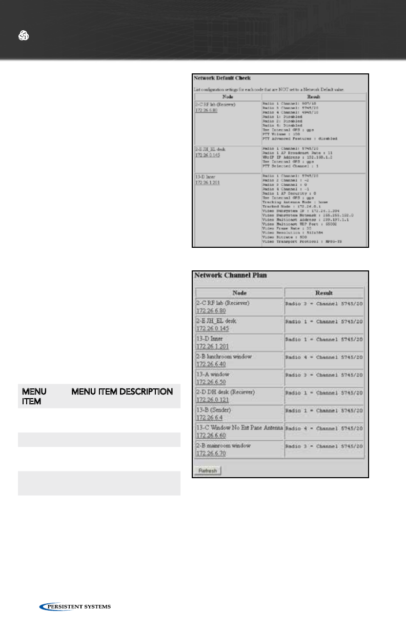
© 2010 - 2015 Persistent Systems, LLC – All Rights Reserved84
WEB MANAGEMENT INTERFACE REFERENCE
NETWORK DEFAULT CHECK
The Network Default Check page
checks and displays which settings on
each node are NOT set to the Network
Default values. If a setting shows up
in this list, it means that that particular
setting on that node is NOT managed
by Network Defaults and will NOT
be changed if the Network Default is
changed.
NETWORK CHANNEL PLAN
The Channel Plan page displays the
channel center frequency and channel
width for every radio of every node in
the node list. Additionally, if “Network
Default” is displayed before the chan-
nel information, it means that that set-
ting is managed by Network Defaults.
MENU
ITEM
MENU ITEM DESCRIPTION
Node Name and IP address of
each node
Result
Radio X Radio(s) in use on each
node
Channel
Y/Z
Channel center frequency/
channel width for each radio
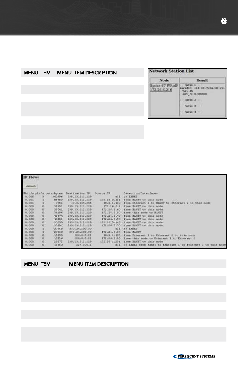
© 2010 - 2015 Persistent Systems, LLC – All Rights Reserved 85
WEB MANAGEMENT INTERFACE REFERENCE
STATION LIST
The Station List page displays the list of 802.11 client stations connected to radios
with 802.11 access point enabled for each node.
IP FLOW LIST
The IP Flow List page displays the list of IP data flows passing through node sorted
by measured throughput.
MENU ITEM MENU ITEM DESCRIPTION
Node Name and IP address of each node
Result
Mbit/s Speed of each IP data flow in Mbps
Pkt/s Number of packets transferred each second for each IP data flow
Total bytes Number of bytes transferred for each IP data flow
Destination IP IP address of destination node
Source IP IP address of source node
Direction/
Interfaces
Direction of and interfaces used by each IP data flow (MANET, Ethernet
X, or this node)
MENU ITEM MENU ITEM DESCRIPTION
Node Name and IP address of each node
Result
Radio X Radio on the node
macaddr MAC address of each client device
connected to the access point
rssi Signal strength to client device
last_rx Time (in seconds) since a packet was
last received
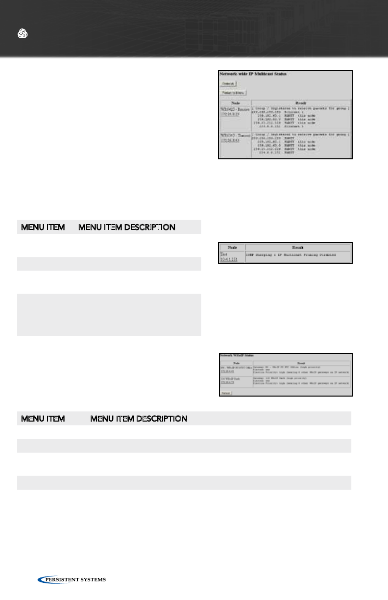
© 2010 - 2015 Persistent Systems, LLC – All Rights Reserved86
WEB MANAGEMENT INTERFACE REFERENCE
IP MULTICAST STATUS
IP Multicast Status displays IGMP Snooping and
IP Multicast Pruning status. This feature shows
a table with a row for each multicast group,
displaying an “F” if that group is forwarded
over the MANET, or a “-” if it is not.
There are known issues with IGMP in Windows
X P.
ATTENTION: PRIOR TO FW VERSION 18.4.0, NETWORK WILL NOT FUNCTION
PROPERLY IF PRUNING STATUS IS NOT CONSISTENT THROUGHOUT THE
NETWORK.
MENU ITEM MENU ITEM DESCRIPTION
Node Name and IP address of each
node
Result
Group Multicast address of nodes con-
nected to managed node
Registered
to receive
packets for
group
Interface used to receive data for
each multicast address (Ethernet
X or MANET)
WRoIP STATUS
WRoIP Status displays the Wave Relay® over IP
gateway status for each node.
MENU ITEM MENU ITEM DESCRIPTION
Node Name and IP address of each node
Result
Gateway Which gateway the node is connected to as well as the priority of that gate-
way
Elected Whether the gateway is elected or not
Election Priority Election priority of the gateway over other gateways/number of other WRoIP
gateways on the IP network.
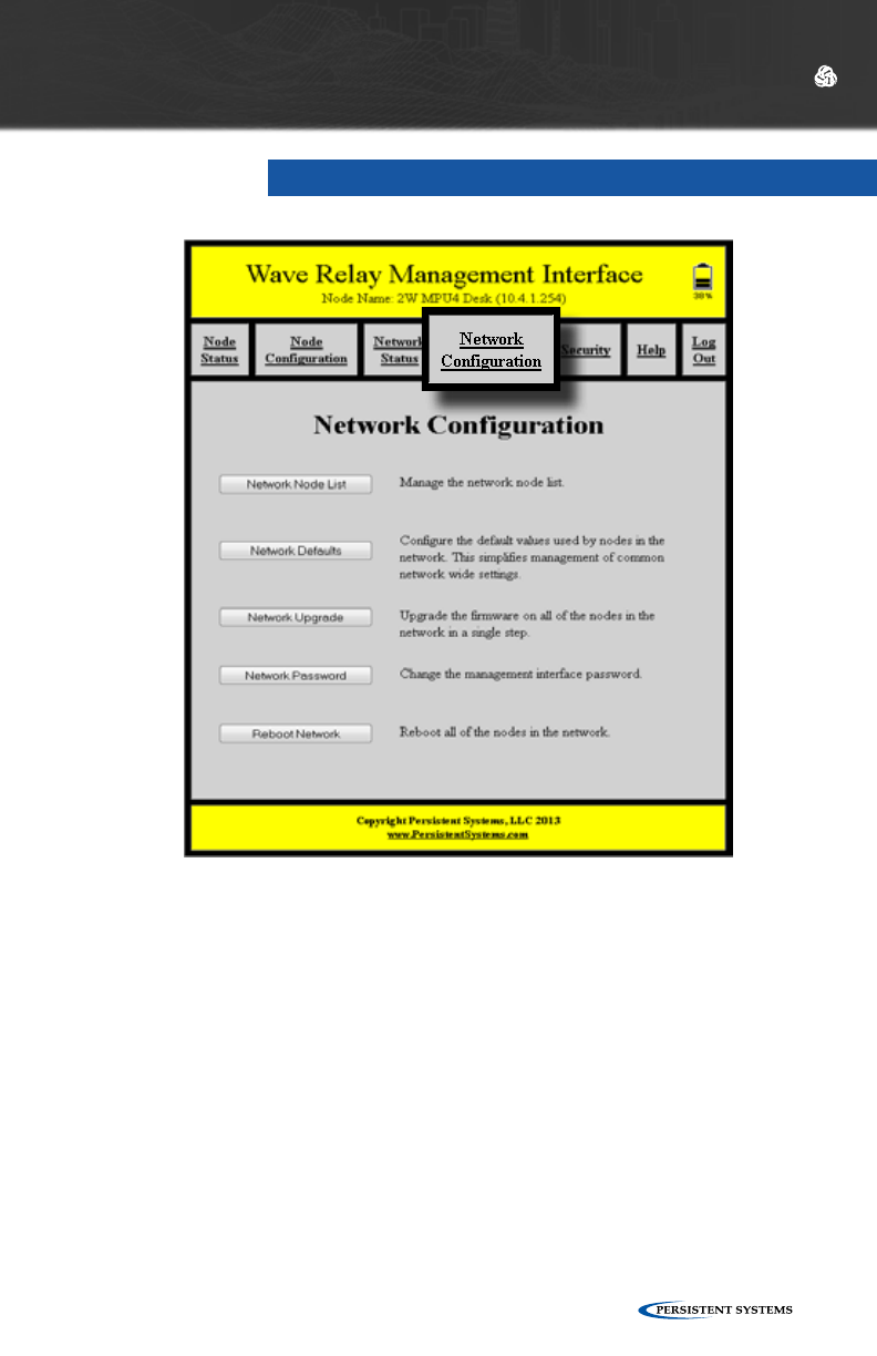
© 2010 - 2015 Persistent Systems, LLC – All Rights Reserved 87
The “Network Configuration” tab contains options to manage the network node list,
configure the network defaults, upgrade and reboot the network, and change the
network password.
NETWORK CONFIGURATION
WEB MANAGEMENT INTERFACE REFERENCE
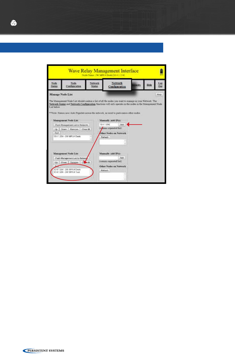
© 2010 - 2015 Persistent Systems, LLC – All Rights Reserved88
WEB MANAGEMENT INTERFACE REFERENCE
NETWORK NODE LIST
WEB MANAGEMENT INTERFACE REFERENCE
The Node List is a list of IP Addresses of nodes managed by the Web Management
Interface.
1. To manage the Node List, click “Network Configuration” > “Network Node
List.”
2. Enter the IP Address of a node in the “Manually Add IP(s)” field and click the
“Add” button to add the node associated with that IP Address to the Node
List. Alternatively, nodes may be added from the “Other Nodes on Network”
window if they are detected by the network. These nodes may be added
individually with the “Selected IPs” button or all at once with the “All” button.
The “Clear Nodes” button will clear the “Other Nodes on Network” window.
3. Repeat this process for every node to be managed. The IP Addresses will
appear in the “Management Node List” window on the left side of the screen
(see screenshot). The Node List may be rearranged and edited from the
“Management Node List” window.
4. When the list is populated with all IP Addresses/Nodes, click the “Push
Management List to Network” button to send the Managed IP List to all nodes
in the network. Node names auto populate across the network.
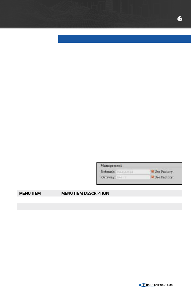
© 2010 - 2015 Persistent Systems, LLC – All Rights Reserved 89
WEB MANAGEMENT INTERFACE REFERENCE WEB MANAGEMENT INTERFACE REFERENCE
NETWORK DEFAULTS
Network Defaults facilitate the management of a large number of nodes. Network
Defaults enable administrators to manage settings on all network nodes specified
in the Node List rather than to manage individual settings on single nodes. Any
changes to Network Defaults will affect only nodes that are in the Node List. To
ensure proper Network Default configuration, confirm that the Node List is current
and configured properly before making changes to Network Defaults. Note that
individual nodes will adopt Network Default settings only if those individual nodes
are configured to use Network Defaults.
SHOW/HIDE ADVANCED FIELDS
For convenience, this button allows you to show (or hide) many of the less frequently
used node configuration fields. The default is to hide the advanced fields (and thus
display a briefer page). If you choose to show the advanced fields, your choice will
remain in effect when you revisit the page. Advanced fields are indicated as such in
the descriptions below.
MANAGEMENT SETTINGS
MENU ITEM MENU ITEM DESCRIPTION
Netmask Defines default netmask for the Web Management Interface
Gateway Defines default gateway for the Web Management Interface

© 2010 - 2015 Persistent Systems, LLC – All Rights Reserved90
WEB MANAGEMENT INTERFACE REFERENCE
RADIO CHANNEL SETTINGS
MENU ITEM MENU ITEM DESCRIPTION
Channel Name Each channel can be assigned a name which to be used in status func-
tions.
Frequency Each radio should be a assigned a frequency. Two radios must be set
to the same frequency in order to communicate. A warning will be
displayed if the frequency setting does not match the radio hardware.
A node with a radio channel set to “Network Default X” in node
configuration will automatically change center frequency and bandwidth
if the settings for “Network Default X” are changed in Network Default
configuration.
Bandwidth Each radio should be assigned a bandwidth. Two radios must be set to
the same bandwidth in order to communicate. Bandwidth should be
increased for shorter distances and decreased for increased distances.
Max Link Dis-
tance
Max Link Distance should be set to the upper bound of how long any
individual link in the network may need to be. All nodes on the network
MUST be set to the same Max Link Distance. A node with a radio channel
set to “Network Default X” in node configuration will automatically change
Max Link Distance if the settings for “Network Default X” are changed in
Network Default configuration.
Channel Density The channel density setting controls how aggressively the radios
compete for access to the shared medium. A number of nodes will be
displayed in parentheses after each menu item. Choose the menu item
that corresponds to the number of nodes in your network. A node with
a radio channel set to “Network Default X” in node configuration will
automatically change Channel Density if the settings for “Network Default
X” are changed in Network Default configuration.
Radio Preference Radio Preference instructs the routing protocol to prefer links on a radio
(consider them lower cost than normal). This can be used to help shift
traffic towards radios running on certain channels.
None: None is the default factory setting. All links are considered
equally.
Medium: Routing protocol is more likely to use this radio to forward
traffic.
High: Routing protocol is significantly more likely to use this radio to forward
traffic.
A node with a radio channel set to “Network Default X” in node
configuration will automatically change Radio Preference if the settings for
“Network Default X” are changed in Network Default configuration.
Each radio must be a assigned a center
frequency and bandwidth. These settings
determine the “channel” on which the node
operates. Up to 16 Network Default channel
settings may be configured to facilitate
management of groups of radios of different
nodes.
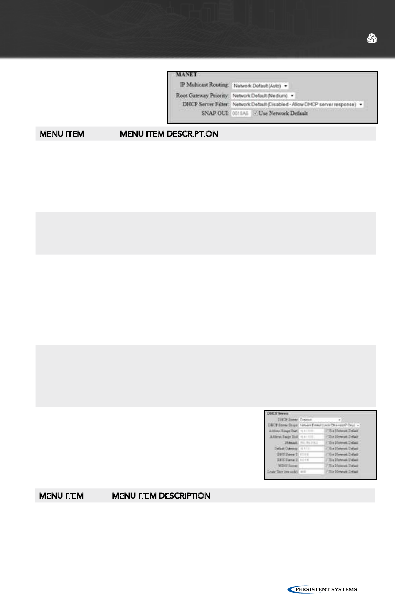
© 2010 - 2015 Persistent Systems, LLC – All Rights Reserved 91
WEB MANAGEMENT INTERFACE REFERENCE
DHCP SERVER (ADVANCED)
If enabled, the DHCP server will serve IP addresses to
devices connected to the node via the wired Ethernet
or wireless 802.11 Access Point interfaces.
MENU ITEM MENU ITEM DESCRIPTION
DHCP Server
Scope
Selects which DHCP clients the DHCP server serves IP addresses to. “Local
Ethernet/AP Only” serves IP addresses to nodes connected via Ethernet or
a wireless 802.11 Access Point. “Entire Network” serves IP addresses to
all nodes in the network. “Local Ethernet/AP Only” is the recommended
setting.
MANET
MENU ITEM MENU ITEM DESCRIPTION
IP Multicast Routing AUTO: Node will prune multicast packets that are not requested
(default, most efficient setting for network).
PULL ALL MULTICAST: Node will accept all multicast packets it hears
on the network. Note: Windows CE/XP computers do not respond
to IGMP Multicast Group Queries sent by Wave Relay nodes. “Pull
All Multicast” should be used in networks with Windows CE/XP
computers to work around this issue.
Root Gateway
Priority (advanced)
HIGH: Any node in your network directly connected to wired
infrastructure should have priority set to “HIGH.”
MEDIUM: All other non-mobile routers should be set to “MEDIUM.”
LOW: Mobile routers should be set to “LOW.”
DHCP Server Filter
(advanced)
ALLOW: Device will pass DHCP messages FROM a DHCP server
which is bridged directly by one of its interfaces. Only the devices
which are directly wired to the switch where the DHCP server resides
need to be set to “ALLOW.”
BLOCK: Device will not bridge any DHCP reply packets that it picks
up off of any of its bridged interfaces. By setting all of the nodes in
the network (except the nodes physically connected to the real DHCP
server) to “BLOCK,” you will ensure that users of your system will
always use the correct DHCP server.
SNAP OUI
(advanced)
Controls the Subnetwork Access Protocol Organizationally Unique
Identifier - The factory OUI, 0018A6, is registered to Persistent Systems,
LLC with the IEEE. SNAP OUI is used to identify Wave Relay® packets.
Changing this field allows the user to obscure which protocol is being
used by the system. All nodes must be set to the same value or they will
not communicate.
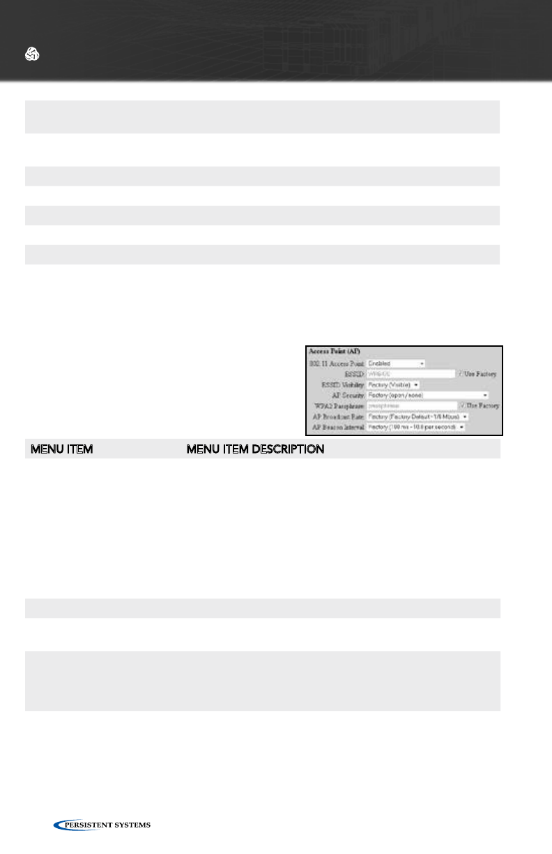
© 2010 - 2015 Persistent Systems, LLC – All Rights Reserved92
WEB MANAGEMENT INTERFACE REFERENCE
ACCESS POINT (AP) SETTINGS
(ADVANCED)
MENU ITEM MENU ITEM DESCRIPTION
802.11 Access Point
(advanced)
Each radio can be configured to function as an 802.11 access
point. Standard clients such as laptops with built in 802.11
cards may access this system. If the AP is disabled, the ESSID
and Beacon Interval configuration options have no effect. For
maximum performance, always disable the 802.11 AP unless
it is required. To use a radio as a 802.11 Access Point, the
radio MUST be set to a valid 802.11 frequency (Numbered
channels in the frequency selection menu i.e. “2412 / 5-20
MHz - Channel 1”) and the channel width MUST be set to 20
MHz.
The following fields are only visible when the 802.11 Access Point is “Enabled.”
ESSID (advanced) Sets the name of the network that the access point advertises
to clients.
ESSID Visibility (advanced) The ESSID can be configured to be “Visible” or “Hidden.”
Generally, the ESSID is configured to be “Visible” to make it
easy for clients to connect to the access point. For additional
security/privacy the ESSID can be configured as “Hidden.”
AP Security (advanced) Enables or disables 802.11 security on the Access Point - Only
WPA2-PSK (Wi-Fi Protected Access v2 with pre-shared keys) is
supported.
Address Range
Start
Start of range of IP addresses assigned to DHCP clients
Address Range
End
End of range of IP addresses assigned to DHCP clients
Netmask Netmask assigned to DHCP clients
Default Gateway Gateway assigned to DHCP clients
DNS Server 1 Primary DNS server assigned to DHCP clients
DNS Server 2 Secondary DNS server assigned to DHCP clients
WINS Server WINS server assigned to DHCP clients
Lease Time DHCP lease time (defaults to 1 hour)
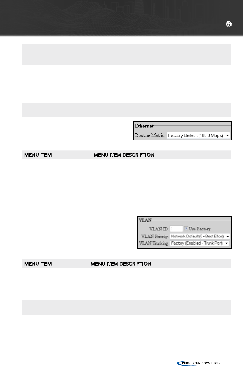
© 2010 - 2015 Persistent Systems, LLC – All Rights Reserved 93
WEB MANAGEMENT INTERFACE REFERENCE
WPA2 Passphrase
(advanced)
Sets a shared passphrase when AP Security is set to WPA2
- The passphrase should be an ASCII string of length 8-63
characters, excluding these characters: ‘,”\&/<>
AP Broadcast Rate
(advanced)
Controls the rate at which broadcasts are transmitted from
an 802.11 Access Point - Increasing this rate can significantly
increase network capacity but will reduce the range of client
connectivity. If the rate is set too high, client devices will have
trouble receiving broadcast packets from the 802.11 access
point.
AP Beacon Interval
(advanced)
The 802.11 access point can send beacons at an interval
between twice and ten times per second.
ETHERNET SETTINGS (ADVANCED)
MENU ITEM MENU ITEM DESCRIPTION
Routing Metric (advanced) Defines link capacity for the routing protocol - A value lower
than the 100 Mbps default should be used when nodes are
connected via non-switched Ethernet (e.g. a third-party
point-to-point wireless link). The metric allows the routing
protocol to make an intelligent decision on if it is better to
route over this Ethernet port or use an alternate route which
is faster.
VLAN SETTINGS (ADVANCED)
MENU ITEM MENU ITEM DESCRIPTION
VLAN ID (advanced) Each VLAN-aware bridge port is assigned a VLAN ID. Un-
tagged frames received by the port are tagged with the speci-
fied VLAN ID. Frames that are sent by the port which have a
VLAN tag matching the specified VLAN ID will have their tags
removed (i.e. they are sent by the port untagged).
VLAN Priority (advanced) Specifies the 802.11 priority of the VLAN tag added to
untagged frames received by this port
VLAN Trunking (advanced) Controls the filtering of VLAN tagged frames that do NOT match
this port’s VLAN ID. When trunking is enabled (trunk port), ALL
non-matching VLAN tagged frames are passed (no filtering).
When trunking is disabled (access port), all non-matching VLAN
tagged frames are blocked (filtered)
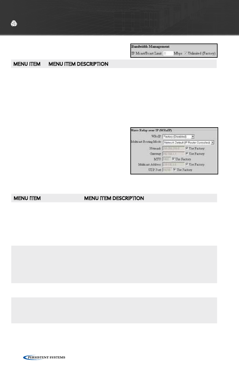
© 2010 - 2015 Persistent Systems, LLC – All Rights Reserved94
BANDWIDTH MANAGEMENT
SETTINGS (ADVANCED)
WAVE RELAY® OVER IP (WROIP)
SETTINGS (ADVANCED)
WRoIP allows the Wave Relay® network to
extend over and seamlessly interact with a
large routed IP network. In order to use this
capability, one or more Wave Relay® nodes
must be setup as WRoIP gateways. A WRoIP
gateway must be directly connected to an
appropriately configured IP router.
WEB MANAGEMENT INTERFACE REFERENCE
MENU ITEM MENU ITEM DESCRIPTION
IP Mcast/
Bcast Limit
(advanced)
Defines the maximum bandwidth allowed for IP multicast or broadcast
network traffic received on the given interface and retransmitted onto the
Wave Relay® network. Traffic in excess of this limit will be dropped. Units are
megabits/sec (Mbps). To disable the limit, set to zero
MENU ITEM MENU ITEM DESCRIPTION
WRoIP (advanced) WRoIP gateway nodes must have the WRoIP protocol
enabled on the interface directly connected to the IP router.
All other nodes should have the WRoIP protocol disabled.
When the WRoIP protocol is enabled on an interface, the
interface will no longer function as a normal Wave Relay®
Ethernet port for connecting Ethernet devices: it will only
work for connecting the IP router.
Multicast Routing Mode
(advanced)
Selects pruning options for multicast traffic:
IP Router Controlled (default): All multicast packets travel
to the cloud network
Wave Relay Controlled: Only subscribed multicast feeds
are passed to the cloud network to reduce network traffic
congestion.
Netmask (advanced) Defines the netmask of the IP subnet specific to the directly
connected IP router interface
Gateway (advanced) Defines the IP address of the IP router in the IP subnet spe-
cific to the directly connected IP router interface - WRoIP
protocol packets will be forwarded to this IP address in
order to be sent over the IP network.
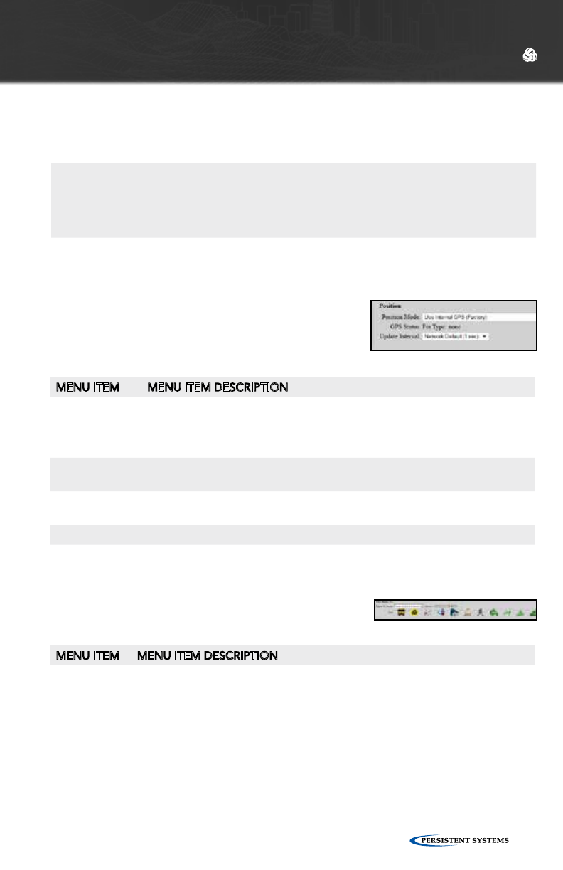
© 2010 - 2015 Persistent Systems, LLC – All Rights Reserved 95
WEB MANAGEMENT INTERFACE REFERENCE
POSITION SETTINGS (ADVANCED)
MENU ITEM MENU ITEM DESCRIPTION
Update Interval Controls how often nodes report information back to visualiziation server
with visualization enabled - A smaller value will result in smoother movement
of mobile nodes in Google™ Earth. A shorter update interval uses more
bandwidth.
ESD UDP Port Defines the port number to receive position updates via an external ESD
feed
External Up-
date UDP Port
Defines the port number to receive position updates via the external Wave
Relay® ‘wr-update-gps’ command
CoT UDP Port Defines the port number to receive position updates via external CoT feed
CDF UDP Port Defines the port number to receive position updates via an external CDF
feed
WAVE RELAY® SA (GOOGLE™ EARTH
NETWORK VISUALIZATION) SETTINGS
MENU ITEM MENU ITEM DESCRIPTION
Report to
Visualization
Server
Enable or disables network visualization for all nodes set to use the Network
Default (typically the whole network) - Visualization is also used by the Tracking
Antenna system and should be enabled on nodes that you wish to be able to
track.
MTU (advanced) Defines the maximum transmissible unit size for the IP net-
work - WRoIP protocol packets sent over the IP network will
be limited to this MTU. All nodes that communicate over
the IP network should be set to the same value.
Multicast Address (advanced) Defines the multicast IP address used by the WRoIP protocol
- The next higher IP multicast address will also be used by the
WRoIP protocol. For example, if 239.255.90.67 is set as the
multicast address, both 239.255.90.67 and 239.255.90.68 will
be used.
UDP Port (advanced) Defines the UDP port used by WRoIP protocol packets
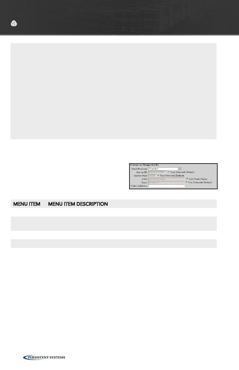
© 2010 - 2015 Persistent Systems, LLC – All Rights Reserved96
WEB MANAGEMENT INTERFACE REFERENCE
MENU ITEM MENU ITEM DESCRIPTION
Send Position Enables or disables transmission of CoT packets to server
Server IP Defines the IP address of the CoT server - This IP address can be a unicast or
multicast address
Server Port Defines the UDP port of the CoT server
Type Defines the contents of the CoT “type” attribute
CURSOR ON TARGET (COT) SETTINGS
(ADVANCED)
This feature enables transmission of local
positioning information to a CoT server on
the network. This feature is not available on
all firmware versions.
SIMPLE SA PACKET GENERATOR (SSPG) (ADVANCED)
These settings exist for backwards compatability with an outdated protocol. See
earlier versions of the manual for more information.
Visualization
Server
(advanced)
Defines the IP address to which nodes will send their visualization updates
(may be either a multicast address [224.0.0.0,239.255.255.255] or the unicast
address of a device running the visualization server.) - The factory default is a
multicast address. When using multicast, each node sends visualization updates
to the entire connected network. All nodes run a visualization server and receive
updates from all other connected nodes. When using unicast, each node sends
visualization updates to the selected address only. If the unicast address is the
management IP address of a node, that node will run a visualization server
to receive the updates. Visualization updates are sent from the management
IP address, so the selected address must be reachable by all nodes with
visualization enabled; it should be either in the same subnet or reachable
through the default gateway. Multicast operation allows the most robust
visualization for mobile networks because it provides true distributed operation
with partitions and merges. Unicast operation requires all visualization users to
be able to contact the selected server, but offers reduced network overhead for
larger static networks.

© 2010 - 2015 Persistent Systems, LLC – All Rights Reserved 97
WEB MANAGEMENT INTERFACE REFERENCE
CHANNEL DEFINITIONS (ADVANCED)
The Wave Relay® Network has 16 channels numbered 0 through 15. Channel 0 is
the Flash Override Channel and has priority over channels 1-15. Channels 1-15
are normal audio channels. Each channel is defined by a Multicast Address and a
Multicast Port. After Channel Definition settings have been configured, click the
“Set All” button.
PTT SETTINGS
MENU ITEM MENU ITEM DESCRIPTION
Enable Push-to-
Talk
Enables or disables the PTT subsystem to allow push-to-talk communi-
cation among voice-equipped devices
Volume Defines the default earpiece volume for headsets - Valid values are 0
through 100. Optimal values vary with headset manufacturer.
Microphone Level Defines the default microphone level for headsets - Valid values are 0
through 100. Optimal values vary with headset manufacturer.
Transmit Mode (advanced)
Transmit on
keypress
Audio is transmitted only when the PTT button is pressed on the
headset.
Transmit
continuously
Audio is continuously transmitted. Other nodes may monitor the
channel only. Selected Channel audio transmissions will interrupt
monitored continuously transmitted audio.
Tones on Transmit
(advanced)
Enables or disables an audible checktone (either Beeps or Verbal) at
the beginning of each transmitted message
Tones on Receive
(advanced)
Enables or disables an audible checktone (either Beeps or Verbal) at
the beginning of each received message
Advanced Features (advanced)
Silynx PTT Head-
set
Enables the serial port on the node (Silynx PTT Headsets require this
setting be enabled)
Microphone
Voltage
Enables +5V power supply voltage on the center pin of the 6-pin head-
set connector (required for some headsets)
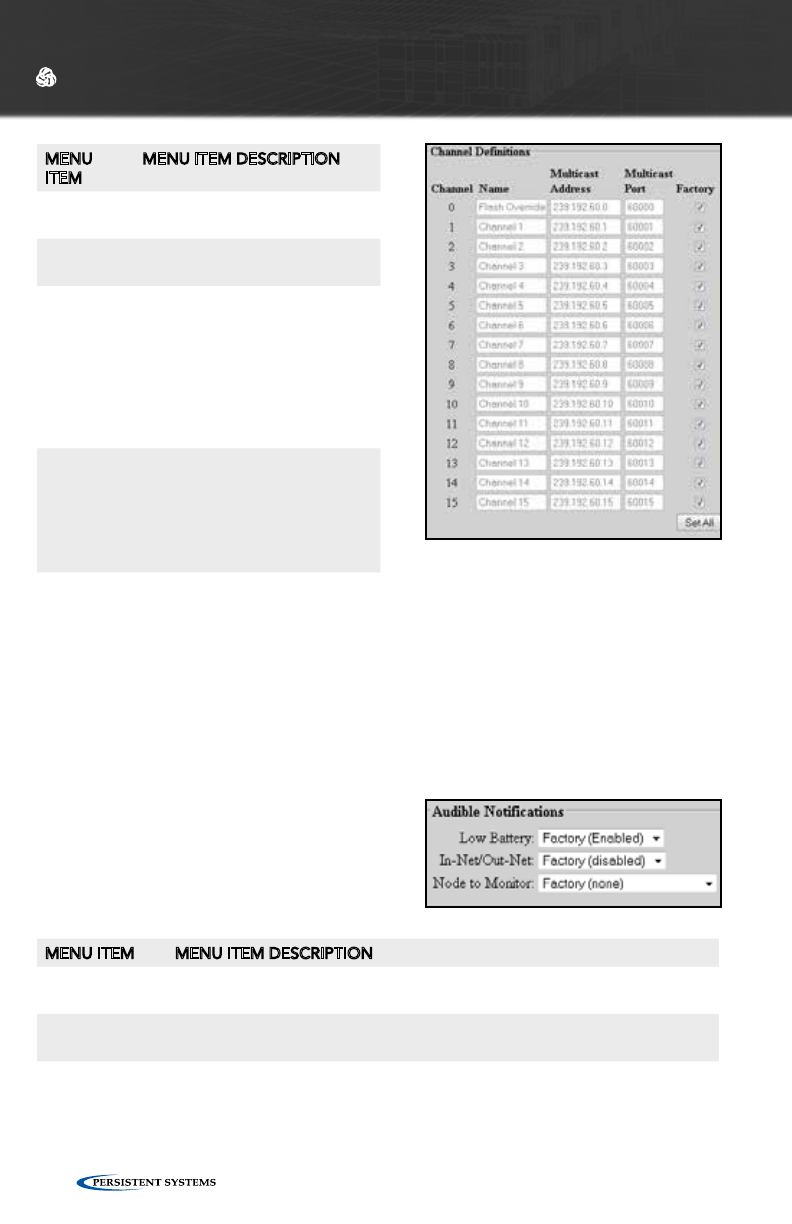
© 2010 - 2015 Persistent Systems, LLC – All Rights Reserved98
WEB MANAGEMENT INTERFACE REFERENCE
MENU
ITEM
MENU ITEM DESCRIPTION
Channel Displays the channel number to
be configured
Name Defines the text name of the
channel
Multicast
Address
Defines the Multicast Ad-
dress for the channel -
Valid values are within the
range of 224.0.0.0 through
239.255.255.255. Note that
each talk group must have a
unique multicast address and
port.
Multicast
Port
Defines the Multicast UDP
port for audio traffic - Valid
values are within the range of 1
through 65534. Note that each
talk group must have a unique
multicast address and port.
AUDIBLE NOTIFICATIONS
MENU ITEM MENU ITEM DESCRIPTION
Low Battery Enables or disables audible notification when the battery is depleted to
5% (notification will occur every 5 minutes)
In-Net/Out-Net Enables or disables an audible notification when a chosen node enters or
leaves the network
Node to
Monitor
Selects a node to monitor for In-Net/Out-Net audible notifications from
the node list
FLASH OVERRIDE
Flash Override is a new feature which allows audio to be sent to all nodes even if
those nodes have selected a different audio channel.
• A flash override transmission is triggered by a “tap-tap-hold” of the PTT
button(button is pressed and released twice quickly in succession immediately
preceding the normal hold for the duration of the transmission.)
• The user will hear a unique “triple” tone on TX and RX to indicate a flash over-
ride.
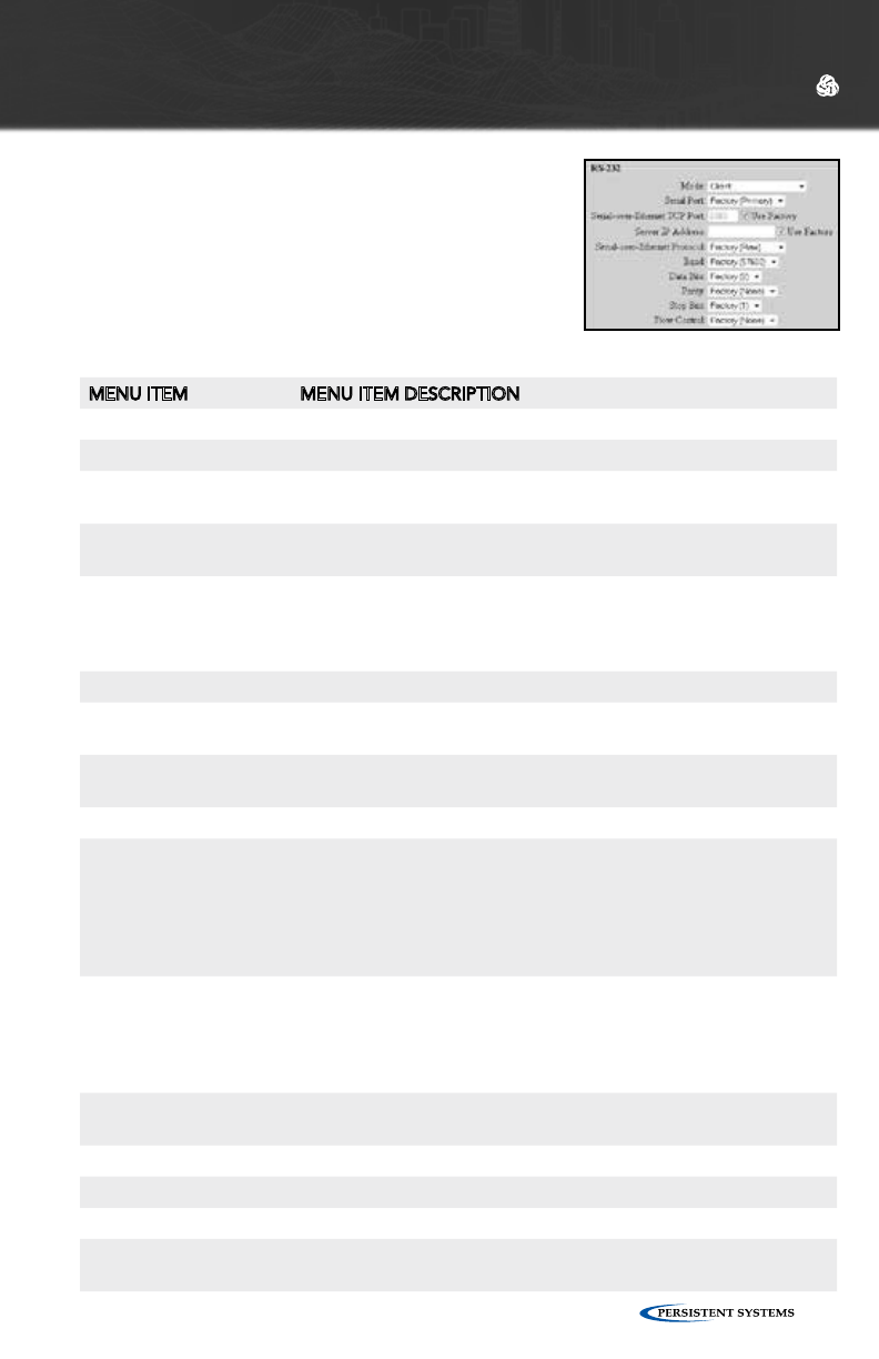
© 2010 - 2015 Persistent Systems, LLC – All Rights Reserved 99
WEB MANAGEMENT INTERFACE REFERENCE
RS-232 SETTINGS (ADVANCED)
The RS-232 serial-over-Ethernet feature can be used
for remote control of a distant serial device via the
Wave Relay® network. A typical application is for a
PC to control a remotely located pan/tilt camera via
a serial link. Two operational modes are supported:
“serial-to-serial” mode and “virtual-to-serial” mode.
For further description, see RS-232 Configuration
Help.
MENU ITEM MENU ITEM DESCRIPTION
Mode
Disabled The serial-over-Ethernet feature is turned off.
Server Use this mode when the device to be controlled (e.g. pan/tilt unit)
is connected to a Wave Relay® device serial port.
Client Use this mode when a controller (e.g. PC) is connected to a Wave
Relay® device serial port.
Echo Mode Instructs the serial port to retransmit any received serial data
out on its transmit pin (useful for debugging serial connections
in cases where Rx/Tx pins might be accidentally reversed in the
cable)
Serial Port (advanced) Selects the primary or secondary RS-232 port on the Wave Relay®.
Serial-over-Ethernet
TCP Port (advanced)
Defines the TCP port for serial-over-Ethernet traffic
Server IP Address (ad-
vanced)
Defines the default IP address of the serial-over-Ethernet server
Serial-over-Ethernet Protocol (advanced)
Raw Serial messages are encapsulated into packets and are
transmitted unaltered over the network. This setting requires
that the RS-232 parameters (baud, parity, etc.) be set correctly at
both ends. This setting is typically used in serial-to-serial mode,
e.g. when a hardware serial controller is used to control a remote
serial device.
Telnet - RFC2217 Serial messages are encapsulated into packets as per RFC2217,
and baud settings are automatically controlled by the protocol.
This setting is typically used in serial-to-virtual mode, e.g. when
a PC with virtual COM ports is used to control a remote serial
device.
Baud (advanced) Valid settings are 300, 1200, 2400, 4800, 9600, 19200, 38400,
57600, or 115200.
Data Bits (advanced) Valid settings are 7 or 8 bits.
Parity (advanced) Valid settings are None, Even, or Odd.
Stop Bits (advanced) Valid settings are 1 or 2 bits.
Flow Control (ad-
vanced)
Valid choices are XON/XOFF (a.k.a. software flow control) or None.
Note that RTS/CTS (a.k.a. hardware flow control) is not supported.

© 2010 - 2015 Persistent Systems, LLC – All Rights Reserved100
WEB MANAGEMENT INTERFACE REFERENCE
DATE/TIME SETTINGS
MENU ITEM MENU ITEM DESCRIPTION
Set local timezone Sets the local time zone as ±12 hours from UTC (settings also
include select US and other global time zones)
NTP Server Address Defines the address, if available, of the NTP (Network Time Proto-
col) server for automatic clock synchronization
Automatic powerdown/powerup
One time only Instructs nodes to perform a one-time power down and power
up at specified times as set in the Set powerdown time and Set
powerup time fields
Daily Instructs nodes to perform a daily powerdown and powerup as
specified in the Set powerdown time and Set powerup time fields
Twice daily Instructs nodes to perform a twice-daily powerdown and powerup
as specified in the Set powerdown time, Set powerup time, Set
2nd powerdown time, and Set 2nd powerup time fields
Hourly Instructs nodes to perform hourly powerdowns and powerups as
specified in the Set powerdown time and Set powerup time fields
- powerdown and powerup times are specified as minutes past
the hour (00 through 59)
Set powerdown time Selects the hour and minute (in local time zone) for unit power-
down - If the powerdown/power up frequency is set to “Hourly,”
then you may only set minutes past the hour.
Set powerup time Selects the hour and minute (in local time zone) for unit powerup -
If the powerdown/powerup frequency is set to “Hourly,” then you
may only set minutes past the hour. If the powerup time is before
the powerdown time, then the powerup happens the next day (or
hour).
Set 2nd powerdown
time
Selects the hour and minute (in local time zone) for second daily power-
down - This setting is valid only when power down/power up frequency is
set to “Twice Daily.”
Set 2nd powerup time Selects the hour and minute (in local time zone) for second daily powerup
- If the powerup time is before the powerdown time, then the powerup
happens the next day (or hour). This setting is valid only when powerdown/
powerup frequency is set to “Twice Daily.”
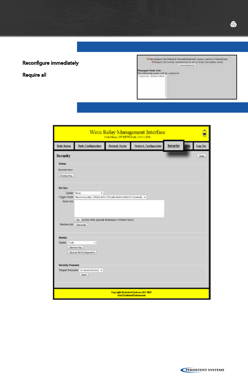
© 2010 - 2015 Persistent Systems, LLC – All Rights Reserved 101
WEB MANAGEMENT INTERFACE REFERENCE
STATUS
The Status box indicates the current security configuration. “Operational” means a
valid key is set and Wave Relay® is operational. If Wave Relay® is NOT operational,
then the node will not communicate with any other nodes, and its management in-
terface can only be accessed via connection to the Ethernet 1 interface. The Security
tab on the navigation bar will have a red background and blink when the current
status is not “Operational.”
SECURITY
SAVE TO NETWORK
Two check boxes are checked by default.
Reconfigure immediately forces the network to
apply the new settings and reboot immediately.
Require all ensures all nodes in the managed
node list receive the updated values or all will fail
and not update.

© 2010 - 2015 Persistent Systems, LLC – All Rights Reserved102
WEB MANAGEMENT INTERFACE REFERENCE
1. From the “Update” menu, select whether to update only the currently managed
node (“Node”) or all nodes on the network. The “network (require all)” setting
will change security settings for all nodes in the network and will require all
nodes in the network be available for any changes to be applied. If not all
nodes are available, no changes will be applied. The “network (any available)”
setting will change security settings for all available nodes on the network.
Nodes that are not available will NOT be updated.
2. Select a Crypto Mode to match your network requirements. The “Crypto
Mode” menu selects the the encryption and authentication algorithms used to
secure Wave Relay® packets. The available set of crypto modes depends on the
node’s hardware capabilities. Newer Wave Relay® products have extra hardware
to support additional Suite-B algorithms (SHA-2 family and GCM) in comparison
to older Wave Relay® products, which do not. If you have a network of only
older hardware, “256-bit AES-CTR with HMAC-SHA-1” will be your only choice.
If you have a network with a mix of older and newer hardware, you should
Crypto Mode 256-bit AES-CTR with
HMAC-SHA-512
256-bit AES-
GCM
256-bit AES-CTR with
HMAC-SHA-1
Encryption Algo-
rithm
256-bit AES in counter mode
Authentication
Algorithm
HMAC-SHA-512 Galois MAC
(GMAC)
HMAC-SHA-1
MAC Tag Length 96-bits
Suite-B Algorithms Yes No (due to SHA-1)
Minimum Key
Length
512-bits (256-bit AES +
256-bit HMAC)
256-bits 512-bits (256-bit AES +
256-bit HMAC)
Maximum Key
Length
1280-bits (256-bit AES
+ 1024-bit HMAC)
256-bits 768-bits (256-bit AES +
512-bit HMAC)
SET KEY
The Set Key box enables users to change the current security configuration.
Changes can be applied to the current node only or to all the nodes in the Network
as specified by the Node List. Ensure all nodes are running the latest firmware
before making changes to the security configuration.
“Error: no security configuration” will be displayed if a node is booted without a key
set. An error will also be displayed if the key has been zeroized (see below).
The current key, if one is set, can be viewed by selecting “Display Key.” Since the
key is displayed in plaintext, view the key in a secure environment only. The “Display
Key” feature indicates the current Crypto Mode, Size, and Value of the key.

© 2010 - 2015 Persistent Systems, LLC – All Rights Reserved 103
WEB MANAGEMENT INTERFACE REFERENCE
ZEROIZE
The Zeroize box enables users to erase the key configuration on an individual node
or on the entire network as specified by the Node List. When a node is zeroized, all
traces of the current key are erased so that the key can no longer be recovered from
the unit. Once a node has been zeroized, it cannot participate in any Wave Relay®
network until it is re-keyed using the “Set Key” function.
1. From the “Update” menu, select whether to update only the currently managed
node (“Node”) or all nodes on the network. The “network (require all)” setting
will zeroize the security configuration for all nodes in the network and will
require all nodes in the network be available for any changes to be applied.
If not all nodes are available, no changes will be applied. The “network (any
available)” setting will zeroize the security configuration for all available nodes
on the network. Nodes that are not available will NOT be updated.
2. Clicking the “Zeroize Key” button will erase the packet encryption key only.
Clicking the “Zeroize All Configuration” button will erase not only the key but
also the management password and the public/private key-pair used to connect
to the Web Management Interface. If the “Zeroize All Configuration” button is
clicked, the node(s) will also reboot.
3. To access the Web Management Interface after the “Zeroize All Configuration”
button has been clicked and the node has rebooted, the user will need to
accept a newly generated certificate and use the factory password to log into
the Web Management Interface.
SECURITY FEATURES
Tamper Response: This menu enables or disables tamper detection. If tamper
detection is enabled, disassembly of the Wave Relay® enclosure will cause a
complete zeroize of the security configuration, including the encryption key, the
management password, and the public/private key-pair used to connect to the Web
Management Interface. This feature is only available on MPU versions of the Wave
Relay®.
select the “Backwards Compatible: 256-bit AES-CTR with HMAC-SHA-1” mode
on the units with newer hardware; this will allow all the nodes in the network
to communicate. If you have a network with only newer hardware you can
select any of the three modes. We recommend “256-bit AES-CTR with HMAC-
SHA-512” as the mode with the greatest security margin. “256-bit AES-GCM” is
an alternate full Suite-B mode that can also be used based on user preference.
3. Once the Crypto Mode is set, enter a key value into the field and click the “Set”
button, or click the “Generate” button to generate a random key. The new key
information is stored to the node or the network.

© 2010 - 2015 Persistent Systems, LLC – All Rights Reserved104
WEB MANAGEMENT INTERFACE REFERENCE
The Wave Relay® router provides an API for configuring and monitoring the radio
outside of the management interface. The API runs over the on-board HTTPS
interface, allowing any program or package that submits requests according to the
HTTP protocol (RFC 2616) to communicate with the Wave Relay®. Some example
programs include custom programs written in Java or C/C++ as well as the Linux
“Curl” command.
A typical request to the Wave Relay® has the form:
https://192.168.5.88/management.cgi?password-
input=XXXXXX&command=param_get&name=WAVERELAY_
IP&name=WAVERELAY_NETMASK
This example URL has the following syntax:
• Protocol: must be https
• Address: use the assigned IP address for the Wave Relay® node (in this example:
192.168.5.88)
• Script name: must be management.cgi
• Required query string field: password-input (the assigned management password
for the node)
• Required query string field: command (the management command to be
performed)
• Additional query string fields: depend on the command. In this example, we are
executing the command param_get in order to request the values for the two
parameters with name=WAVERELAY_IP and name=WAVERELAY_NETMASK
Additional documentation on the Wave Relay® API can be found in the Wave Relay®
Management API document available upon request.
WAVE RELAY® API

© 2010 - 2015 Persistent Systems, LLC – All Rights Reserved 105
WEB MANAGEMENT INTERFACE REFERENCE

© 2010 - 2015 Persistent Systems, LLC – All Rights Reserved106
TROUBLE-
SHOOTING

© 2010 - 2015 Persistent Systems, LLC – All Rights Reserved 107
TROUBLESHOOTING
COMMON PROBLEMS AND TROUBLESHOOTING
This section contains a list of troubleshooting steps to follow when two or more
nodes are unable to communicate.
The following must be configured correctly for Wave Relay® nodes to communicate:
1. Encryption Key and Type
2. Radio Enabled
3. Channel Frequency and Channel Width
4. Firmware Version
5. Mesh Routing Enabled
6. Antenna Connected

© 2010 - 2015 Persistent Systems, LLC – All Rights Reserved108
TROUBLESHOOTING
SYMPTOM POTENTIAL ROOT
CAUSE
POTENTIAL SOLUTION
NODES ARE UN-
ABLE TO COM-
MUNICATE
NODES NOT
POWERED ON
1. Check for depleted batteries and/or discon-
nected power cables.
INADEQUATE
POWER SUPPLY
1. MPU3/MPU4 can require as much as 18W
of peak power to operate. Quads (with 2W
radio) can require as much as 60W.
2. Ensure that 60W PoE injector is being used.
3. Ensure other power sources are adequate.
CRYPTO MODE
AND/OR CRYPTO
KEY SET INCOR-
RECTLY
1. The Crypto Mode and Crypto Key must be
the same on all nodes. e.g. AES-256 + SHA1
will not communicate with AES-256 + SHA-
512.
2. To check the Crypto Mode setting, click
“Security” > “Display Key” and ensure that
the Crypto Mode setting is the same on all
nodes.
3. On the same page, ensure that the Crypto
Key is the same on all nodes.
RADIOS NOT
ENABLED
1. Depending on node type, several radios
may be available. At least one radio must be
enabled for the node to communicate.
2. To enable a radio, click “Node Configuration”
> “Node Configuration.” Ensure “Enabled” is
selected from the drop-down menu.
FREQUENCY
AND/OR CHAN-
NEL WIDTH SET
INCORRECTLY
1. Radios must be on the same Center
Frequency and the same Channel Width in
order to communicate. e.g. a node on 2412
MHz, Width = 5MHz will not communicate
with 2412 MHz Width = 20MHz.
2. To set Frequency and/or Channel Width,
click “Node Configuration” > “Node
Configuration.” In the Configuration Settings
for an available Radio, ensure that the Center
Frequency AND the Channel Width are the
same on all nodes. Note that depending on
the type of radio module installed, specific
frequencies may not be available.

© 2010 - 2015 Persistent Systems, LLC – All Rights Reserved 109
TROUBLESHOOTING
MAX LINK
DISTANCE SET
INCORRECTLY
1. Radios are able to communicate when set to
different link distances but will result in sub-
optimal performance.
2. To set Max Link Distance correctly, determine
the farthest distance any individual link on this
frequency may need to be, then choose the
next longest Max Link Distance. e.g. 13 mi =
Max Link Distance should be set to 15 mi.
3. Click “Node Configuration” > “Node Con-
figuration.” Ensure that the Max Link Distance
is correct and the same on all radios on the
same frequency.
INCOMPATIBLE
FIRMWARE VER-
SIONS
1. All nodes must be running the same major
firmware version in order to communicate.
e.g. a node with firmware version 17.X.X will
not communicate with a node with firmware
version 18.X.X.
2. To check the firmware version of a node, click
“Node Status” > “Unit Info.” The firmware
version will be displayed at the top of the
list. If firmware versions are not the same, up-
grade the nodes to the same firmware version
(see “Node Upgrade”).
MESH ROUTING
DISABLED
1. If mesh routing is disabled on the radio, it will
not participate in the routing protocol and
will not communicate with its neighbor nodes.
2. To enable mesh routing, click “Node
Configuration” > “Node Configuration.”
Click on the “Show Advanced Fields”
button if Advanced Fields are hidden. In the
Configuration Settings for the desired radio,
ensure that Mesh Routing is set to “Enabled.”
ANTENNA CON-
NECTED TO
WRONG RADIO
1. The node that is being configured may have
several available radios. Ensure that an an-
tenna is connected to the correct RF port on
the node that is being configured. Addition-
ally, ensure that the antenna is for the correct
frequency band for that radio.

© 2010 - 2015 Persistent Systems, LLC – All Rights Reserved110
TROUBLESHOOTING
POOR/LOW
THROUGHPUT
RF INTERFER-
ENCE
1. As a general rule of thumb, if there is no RF
interference and nodes are in proximity to
each other, a 20MHz channel should observe
approximately 20Mbps throughput, a 10MHz
channel should observe approximately
10Mbps, and a 5MHz channel should observe
approximately 5Mbps.
2. If low throughput is measured, test other
center frequencies until you achieve the
highest throughput possible for a given
channel width.
3. Resolve interference issue with other
transmitter located nearby.
MAX LINK
DISTANCE SET
INCORRECTLY
1. If Max Link Distance is set incorrectly and/or
inconsistently in a network, throughput will be
affected negatively. To set Max Link Distance
correctly, determine the farthest distance any
individual link on this frequency may need to
be, then choose the next longest Max Link
Distance. e.g. 13 mi = Max Link Distance
should be set to 15 mi. To set Max Link
Distance, click “Node Configuration” > “Node
Configuration.”
CHANNEL DEN-
SITY SET INCOR-
RECTLY
1. If Channel Density is set incorrectly and/
or inconsistently in a network, throughput
will be affected negatively. To set Channel
Density, click “Node Configuration” > “Node
Configuration.” Channel Density should be
set by the number of nodes in the network.
BLADE ANTEN-
NA DOES NOT
HAVE A GOOD
(METALLIC)
GROUND PLANE
1. Install a proper metallic ground plane.
POOR AUDIO MICROPHONE
VOLTAGE NOT
ENABLED (MPU3
AND QUAD
ONLY)
1. Microphone voltage must be enabled for use
with certain headsets.
2. To enable microphone voltage, click “Node
Configuration” > “PTT Configuration” > “Ac-
cessory Features.”
MICROPHONE
GAIN NOT SET
TO AUTO
1. To set microphone gain to auto, click “Node
Configuration” > “PTT Configuration” > “Mi-
crophone Level” > enter “auto” into the field.

© 2010 - 2015 Persistent Systems, LLC – All Rights Reserved 111
MULTICAST
TRAFFIC STOPS
AFTER A FEW
SECONDS
PRUNING STA-
TUS SET INCOR-
RECTLY (FW
VERSIONS 18.3.X
AND EARLIER
ONLY)
1. Prior to FW version 18.4.0, if pruning status
is not the same on all nodes in the network,
then multicast traffic will not forward properly.
2. To check Pruning status, click “Network
Status” > “IP Multicast Status.” If any nodes
in the network have pruning status disabled,
the page will report a message of “pruning
disabled.”
CLIENT DEVICE
IS USING WIN-
DOWS CE/XP
1. Windows CE/XP computers have a known
issue where they do not respond to IGMP
Multicast Group Queries sent by Wave Relay
nodes. “Pull All Multicast” should be used on
Windows CE/XP computers to work around
this issue. Pruning must be disabled on all
nodes with FW versions 18.3.x and earlier or
set to “Pull All Multicast” on all nodes with
FW version 18.4.0 and later.
2. To disable pruning on FW versions 18.3.x and
earlier, navigate to the “Network Defaults”
page. Set IGMP Snooping & IP Multicast
Pruning to “Disabled.”
3. On FW versions 18.4.0 and later, set IP
Multicast Routing to “Pull All Multicast”
in the “Node Configuration” or “Network
Defaults” page.
TROUBLESHOOTING

© 2010 - 2015 Persistent Systems, LLC – All Rights Reserved112
HARDWARE
DETAILS

© 2010 - 2015 Persistent Systems, LLC – All Rights Reserved 113
HARDWARE DETAILS

© 2010 - 2015 Persistent Systems, LLC – All Rights Reserved114
MAN PORTABLE UNIT
— GEN4

© 2010 - 2015 Persistent Systems, LLC – All Rights Reserved 115
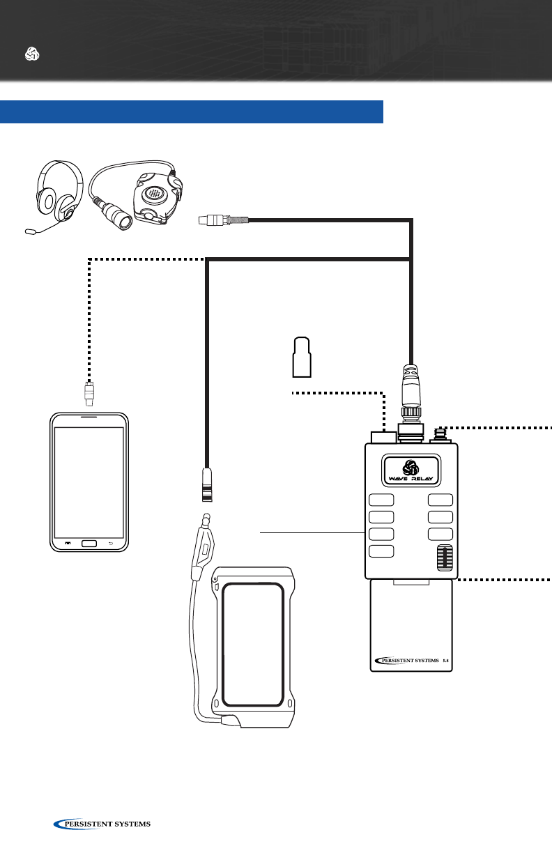
© 2010 - 2015 Persistent Systems, LLC – All Rights Reserved116
HARDWARE DETAILS
MAN PORTABLE UNIT — GEN4
MAN PORTABLE
UNIT 4
WR-MPU4-XX
Battery
Eliminator
CBL-054
High-
Performance
Ground-to-Air
WR-ANT-059
2.3 - 2.5 GHz
Antenna
Options
Audio Options
Springbase
Adapter
CBL-085
PULL TO REVEAL SMB
DO NOT USE
IN JAVELIN
0
+
+
-
-
-
100
(2) (5)
(1)
(4)
12V
12V
(3)
SOC
PINS
2-5
SOC
PINS
1-4
SW
(6)
MPU4 Pouch
MOLLE-MPU4-2
BA-2557 Pouch
MOLLE-BA-2557
BA-2590 Pouch
MOLLE-BA2590
Transit Case
CASE-017
CASE & POUCH OPTIONS
Battery
BAT-06
(Included with
WR-MPU4-XX)
Battery Charging Adapter
BAT-07
Battery
BAT-06
760 - 780 MHz
WR-ANT-051
2.3 - 2.5 GHz
WR-ANT-053
5.1 - 5.9 GHz
WR-ANT-052
GPS Stub
Antenna
WR-ANT-071
6-Pin
Connectors
CBL-116
CBL-118
6-pin to
Micro USB
Adapter
Cable
CBL-117
19-Pin to 6-Pin Connector
CBL-115
Samsung™ Galaxy
Note Ruggedized
Enclosure
MOLLE-IP67-NOTE
Android™ Smart
Phone
902 - 928 MHz
WR-ANT-073
4.4 - 5.0 GHz
WR-ANT-081
0
+
+
-
-
-
100
(2) (5)
(1)
(4)
12V
12V
(3)
SOC
PINS
2-5
SOC
PINS
1-4
SW
(6)
PULL TO REVEAL SMB
DO NOT USE
IN JAVELIN
Battery
Charger
BAT-05
(fits 4 Battery
Charging
Adapters)
POWER OPTIONS
BA-2557
BAT-08
BA-2590
BAT-02
BATTERY
CHARGING
ADAPTER
BAT-03BAT-04
Two-Bay
Battery
Charger
BAT-11
(fits 2 MPU4
Batteries)
Headset &
Push-To-Talk
Adapter
WR-ACC-067
Android™ EUD
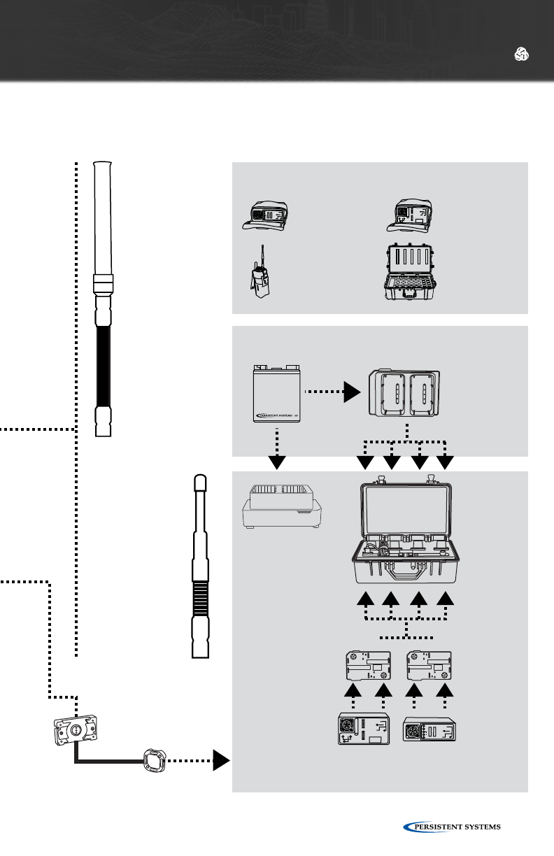
© 2010 - 2015 Persistent Systems, LLC – All Rights Reserved 117
HARDWARE DETAILS
MAN PORTABLE
UNIT 4
WR-MPU4-XX
Battery
Eliminator
CBL-054
High-
Performance
Ground-to-Air
WR-ANT-059
2.3 - 2.5 GHz
Antenna
Options
Audio Options
Springbase
Adapter
CBL-085
PULL TO REVEAL SMB
DO NOT USE
IN JAVELIN
0
+
+
-
-
-
100
(2) (5)
(1)
(4)
12V
12V
(3)
SOC
PINS
2-5
SOC
PINS
1-4
SW
(6)
MPU4 Pouch
MOLLE-MPU4-2
BA-2557 Pouch
MOLLE-BA-2557
BA-2590 Pouch
MOLLE-BA2590
Transit Case
CASE-017
CASE & POUCH OPTIONS
Battery
BAT-06
(Included with
WR-MPU4-XX)
Battery Charging Adapter
BAT-07
Battery
BAT-06
760 - 780 MHz
WR-ANT-051
2.3 - 2.5 GHz
WR-ANT-053
5.1 - 5.9 GHz
WR-ANT-052
GPS Stub
Antenna
WR-ANT-071
6-Pin
Connectors
CBL-116
CBL-118
6-pin to
Micro USB
Adapter
Cable
CBL-117
19-Pin to 6-Pin Connector
CBL-115
Samsung™ Galaxy
Note Ruggedized
Enclosure
MOLLE-IP67-NOTE
Android™ Smart
Phone
902 - 928 MHz
WR-ANT-073
4.4 - 5.0 GHz
WR-ANT-081
0
+
+
-
-
-
100
(2) (5)
(1)
(4)
12V
12V
(3)
SOC
PINS
2-5
SOC
PINS
1-4
SW
(6)
PULL TO REVEAL SMB
DO NOT USE
IN JAVELIN
Battery
Charger
BAT-05
(fits 4 Battery
Charging
Adapters)
POWER OPTIONS
BA-2557
BAT-08
BA-2590
BAT-02
BATTERY
CHARGING
ADAPTER
BAT-03BAT-04
Two-Bay
Battery
Charger
BAT-11
(fits 2 MPU4
Batteries)
Headset &
Push-To-Talk
Adapter
WR-ACC-067
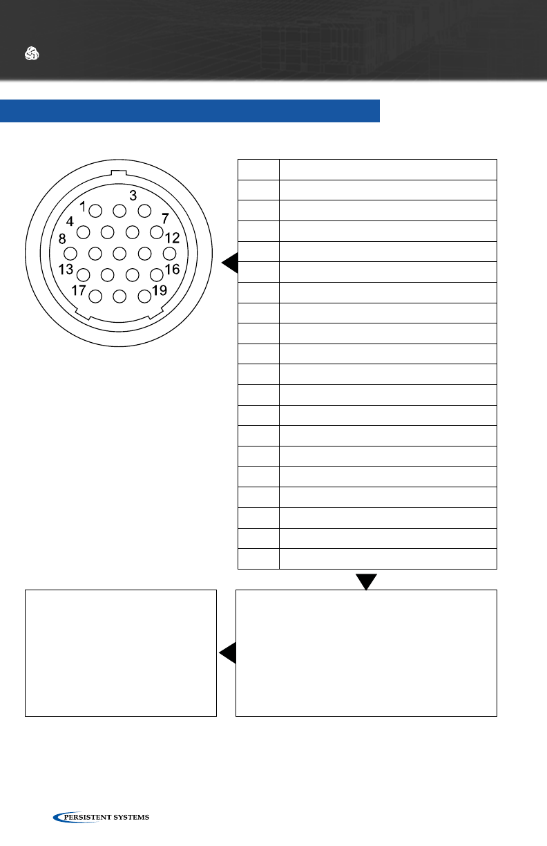
© 2010 - 2015 Persistent Systems, LLC – All Rights Reserved118
I/O CONNECTION - MPU4
PIN DESCRIPTION
1 Ethernet 2 RXN (RJ45 pin 6)
2 Ethernet 2 TXN (RJ45 pin 2)
3 Audio GND
4 Ethernet 1 RXP (RJ45 pin 3)
5 Ethernet 2 RXP (RJ45 pin 3)
6 Ethernet 2 TXP (RJ45 pin 1)
7 Audio Input (Microphone)
8 Ethernet 1 TXN (RJ45 pin 2)
9 Ethernet 1 RXN (RJ45 pin 6)
10 GPIO
11 Audio PTT or RS-232 WR Tx/Dev Rx
12 Audio Output (Speaker)
13 Ethernet 1 TXP (RJ45 pin 1)
14 Power GND
15 RS-232 Wave Relay® Rx/Device Tx
16 +5V Accessory Power (1 Amp Max)
17 3.3V Accessory Power (5 Amp Max)
18 +10-48VDC (VIN)
19 LED GND (Switched)
WHAT TO CONNECT
CBL-043 → I/O to Ethernet + PoE
CBL-035/CBL-077 → I/O to AID
CONNECTOR INFORMATION
•Glenair 801 Series “Mighty Mouse”
Connector
•IP67 Rated in the Mated State
HARDWARE DETAILS
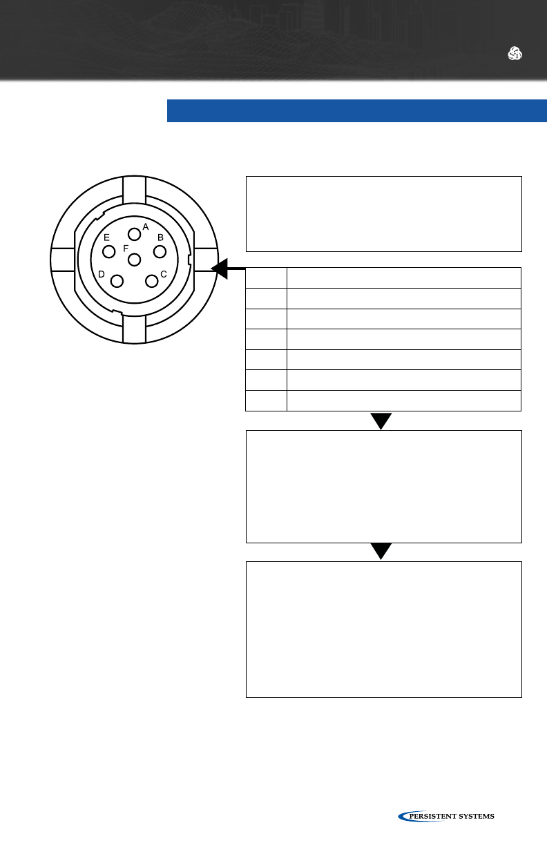
© 2010 - 2015 Persistent Systems, LLC – All Rights Reserved 119
PIN DESCRIPTION
A Ground
B Audio Output (speaker)
C Audio PTT or RS-232 WR Tx/Dev Rx
D Audio Input (microphone)
E RS-232 Wave Relay® Rx/Device Tx
F +5V Accessory Power
NOTE
The PTT Audio connections for the MPU4
is not wired the same as the MPU3 or Quad
Radio Router.
CONNECTOR INFORMATION
•NATO U-283/U Standard Wiring for PTT
Devices
•IP67 Rated
WHAT TO CONNECT
WR-ACC-067, WR-ACC-079
PTT AUDIO - MPU4 AID
HARDWARE DETAILS
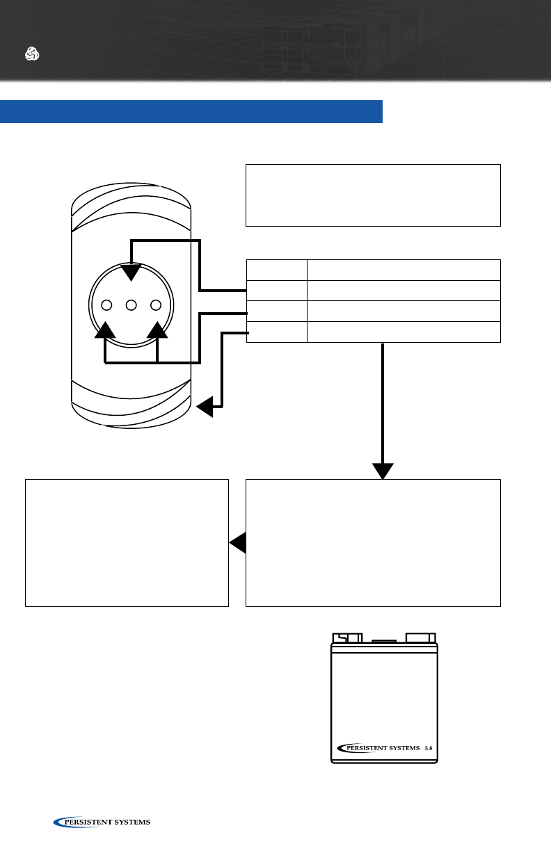
© 2010 - 2015 Persistent Systems, LLC – All Rights Reserved120
BATTERY TWIST-LOCK CONNECTION - MPU4
HARDWARE DETAILS
WHAT TO CONNECT
Included: BAT-06
Battery Eliminator: CBL-054
Compatible With:
PRC-148 Thales MBITR Battery
PRC-152 Harris Falcon III Battery
POWER SPECIFICATIONS
Voltage Range: 8-30 VDC
CONNECTOR INFORMATION
•IP67 Rated
•Used to power an MPU4 when not using
19-pin I/O PoE functionality
PIN DESCRIPTION
Center Smart I/O
Outer Power
Flange Ground

© 2010 - 2015 Persistent Systems, LLC – All Rights Reserved 121
HARDWARE DETAILS

© 2010 - 2015 Persistent Systems, LLC – All Rights Reserved122
MAN PORTABLE UNIT
— GEN3

© 2010 - 2015 Persistent Systems, LLC – All Rights Reserved 123
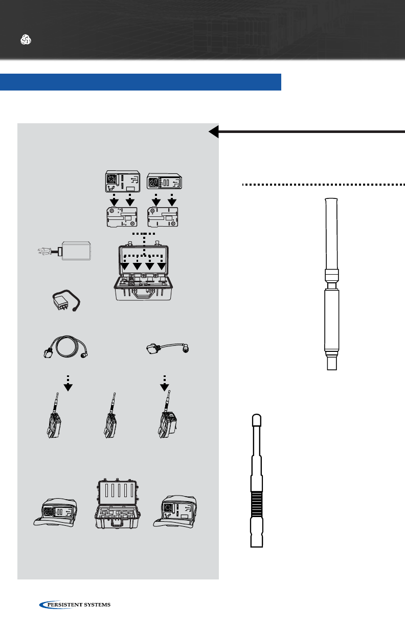
© 2010 - 2015 Persistent Systems, LLC – All Rights Reserved124
MAN PORTABLE UNIT — GEN3
HARDWARE DETAILS
Camera
Auxiliary Input
Device (AID)
WR-AID-01
GPS Antenna
WR-ANT-040
(2 foot cable)
WR-ANT-040L
(10 foot cable)
MAN PORTABLE
UNIT 3
With One Radio: WR-MPU3-XX
With Two Radios: WR-MPU3-XXXX
19-Pin to Ethernet Cable
CBL-043
Standard
Ethernet
Cable
CBL-046
Computer
To Power
- 8-48V DC Input
Springbase
Adaptor
CBL-085
High-
Performance
Ground-to-Air
WR-ANT-059
2.3 - 2.5 GHz
Audio Options
Antenna Options
19-Pin to
19-Pin Cable
CBL-035 (Standard)
CBL-098 (Ultra Flexible)
Headset & Push-To-
Talk Adapter
WR-ACC-067
POWER OPTIONS
5 inch Battery Cable
CBL-045
24 inch Battery Cable
CBL-037
Wall Power Supply
CBL-063
BA-2557
BAT-08
BA-2590
BAT-02
BATTERY
CHARGING
ADAPTER
MPU3/BA-2557
Pouch
CASE-011
BA-2557
Pouch
CASE-020
BA-2590
Pouch
MOLLE-BB2590
MPU3
Pouch
CASE-015
MPU3 Dual
Pouch
CASE-019
0
+
+
-
-
-
100
(2) (5)
(1)
(4)
12V
12V
(3)
SOC
PINS
2-5
SOC
PINS
1-4
SW
(6)
CASE & POUCH OPTIONS
Battery Charger
BAT-05
(fits 4 Battery Charging Adapters)
BAT-03BAT-04
Outdoor PoE Injector
WR-PWR-48V - 60W
PULL TO REVEAL SMB
DO NOT USE
IN JAVELIN
0
+
+
-
-
-
100
(2) (5)
(1)
(4)
12V
12V
(3)
SOC
PINS
2-5
SOC
PINS
1-4
SW
(6)
PULL TO REVEAL SMB
DO NOT USE
IN JAVELIN
Transit Case
CASE-012
1.3 - 1.39 GHz
WR-ANT-084
760 - 780 MHz
WR-ANT-051
2.3 - 2.5 GHz
WR-ANT-053
5.1 - 5.9 GHz
WR-ANT-052
902 - 928 MHz
WR-ANT-073
4.4 - 5.0 GHz
WR-ANT-081
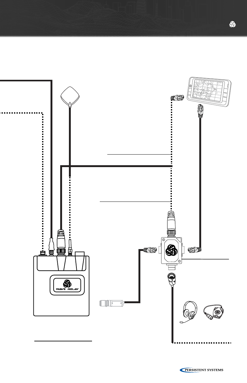
© 2010 - 2015 Persistent Systems, LLC – All Rights Reserved 125
HARDWARE DETAILS
Camera
Auxiliary Input
Device (AID)
WR-AID-01
GPS Antenna
WR-ANT-040
(2 foot cable)
WR-ANT-040L
(10 foot cable)
MAN PORTABLE
UNIT 3
With One Radio: WR-MPU3-XX
With Two Radios: WR-MPU3-XXXX
19-Pin to Ethernet Cable
CBL-043
Standard
Ethernet
Cable
CBL-046
Computer
To Power
- 8-48V DC Input
Springbase
Adaptor
CBL-085
High-
Performance
Ground-to-Air
WR-ANT-059
2.3 - 2.5 GHz
Audio Options
Antenna Options
19-Pin to
19-Pin Cable
CBL-035 (Standard)
CBL-098 (Ultra Flexible)
Headset & Push-To-
Talk Adapter
WR-ACC-067
POWER OPTIONS
5 inch Battery Cable
CBL-045
24 inch Battery Cable
CBL-037
Wall Power Supply
CBL-063
BA-2557
BAT-08
BA-2590
BAT-02
BATTERY
CHARGING
ADAPTER
MPU3/BA-2557
Pouch
CASE-011
BA-2557
Pouch
CASE-020
BA-2590
Pouch
MOLLE-BB2590
MPU3
Pouch
CASE-015
MPU3 Dual
Pouch
CASE-019
0
+
+
-
-
-
100
(2) (5)
(1)
(4)
12V
12V
(3)
SOC
PINS
2-5
SOC
PINS
1-4
SW
(6)
CASE & POUCH OPTIONS
Battery Charger
BAT-05
(fits 4 Battery Charging Adapters)
BAT-03BAT-04
Outdoor PoE Injector
WR-PWR-48V - 60W
PULL TO REVEAL SMB
DO NOT USE
IN JAVELIN
0
+
+
-
-
-
100
(2) (5)
(1)
(4)
12V
12V
(3)
SOC
PINS
2-5
SOC
PINS
1-4
SW
(6)
PULL TO REVEAL SMB
DO NOT USE
IN JAVELIN
Transit Case
CASE-012
1.3 - 1.39 GHz
WR-ANT-084
760 - 780 MHz
WR-ANT-051
2.3 - 2.5 GHz
WR-ANT-053
5.1 - 5.9 GHz
WR-ANT-052
902 - 928 MHz
WR-ANT-073
4.4 - 5.0 GHz
WR-ANT-081
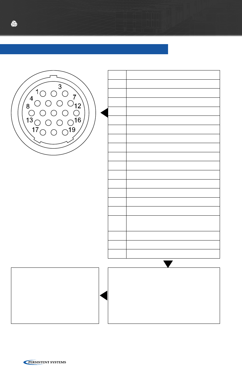
© 2010 - 2015 Persistent Systems, LLC – All Rights Reserved126
HARDWARE DETAILS
I/O CONNECTION - MPU3
PIN DESCRIPTION
1 Ethernet 2 RXN (RJ45 pin 6)
2 Ethernet 2 TXN (RJ45 pin 2)
3 Audio GND
4 Ethernet 1 RXP (RJ45 pin 3)
5 Ethernet 2 RXP (RJ45 pin 3)
6 Ethernet 2 TXP (RJ45 pin 1)
7 Audio Input (Microphone)
8 Ethernet 1 TXN (RJ45 pin 2)
9 Ethernet 1 RXN (RJ45 pin 6)
10 N/C
11 Audio PTT
12 Audio Output (Speaker)
13 Ethernet 1 TXP (RJ45 pin 1)
14 Power GND
15 Wave Relay® Tx/Device Rx
16 RS-232 Wave Relay® Rx/Dev Tx or
+5V Accessory Power (1 Amp Max)
17 3.3V Accessory Power (3 Amp Max)
18 +10-48VDC (VIN)
19 LED GND (Cathode)
HOW TO CONNECT
CBL-043 → I/O to Ethernet + PoE
CBL-035/CBL-077 → I/O to AID
CONNECTOR INFORMATION
•Glenair 801 Series “Mighty Mouse”
Connector
•IP67 Rated in the Mated State
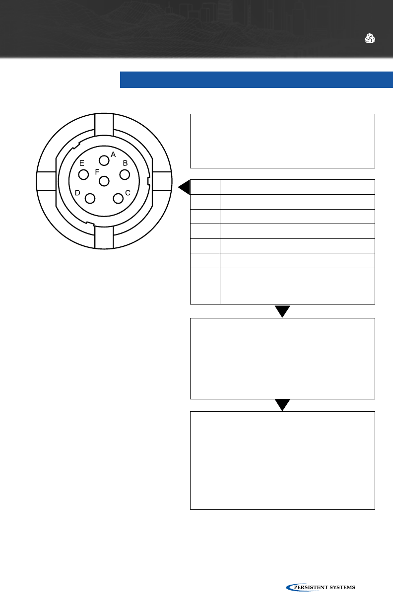
© 2010 - 2015 Persistent Systems, LLC – All Rights Reserved 127
PTT AUDIO - MPU3 AID
HARDWARE DETAILS
PIN DESCRIPTION
A Ground
B Audio Output (speaker)
C Audio Push-To-Talk
D Audio Input (microphone)
E RS-232 Wave Relay® Tx/Dev Rx
F RS-232 Wave Relay® Rx/Dev Tx
or
+5V Accessory Power (1 Amp Max)
NOTE
The PTT Audio connections on the MPU3
and the MPU4 are NOT wired identically.
CONNECTOR INFORMATION
•NATO U-283/U Standard Wiring for PTT
Devices
•IP67 Rated
WHAT TO CONNECT
WR-ACC-067, WR-ACC-079
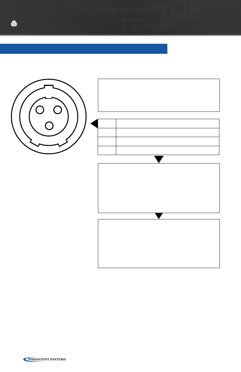
© 2010 - 2015 Persistent Systems, LLC – All Rights Reserved128
AUXILIARY POWER - MPU3
HARDWARE DETAILS
PIN DESCRIPTION
A Ground
B Power IN
C N/C
POWER SPECIFICATIONS
Voltage Range: 8-48 VDC
Maximum Current: 5 Amps
CONNECTOR INFORMATION
•Glenair 801 Series “Mighty Mouse” Connector
•IP67 Rated in the Mated State
•Used to power an MPU3 when not utilizing the
19pin I/O PoE fuction
WHAT TO CONNECT
CBL-037, 045 → PWR to BA-2557, BA-2590,
BA-5590
CBL-059 → PWR to Vehicle DC Power Port
A
BC

© 2010 - 2015 Persistent Systems, LLC – All Rights Reserved 129
HARDWARE DETAILS

© 2010 - 2015 Persistent Systems, LLC – All Rights Reserved130
QUAD RADIO ROUTER

© 2010 - 2015 Persistent Systems, LLC – All Rights Reserved 131
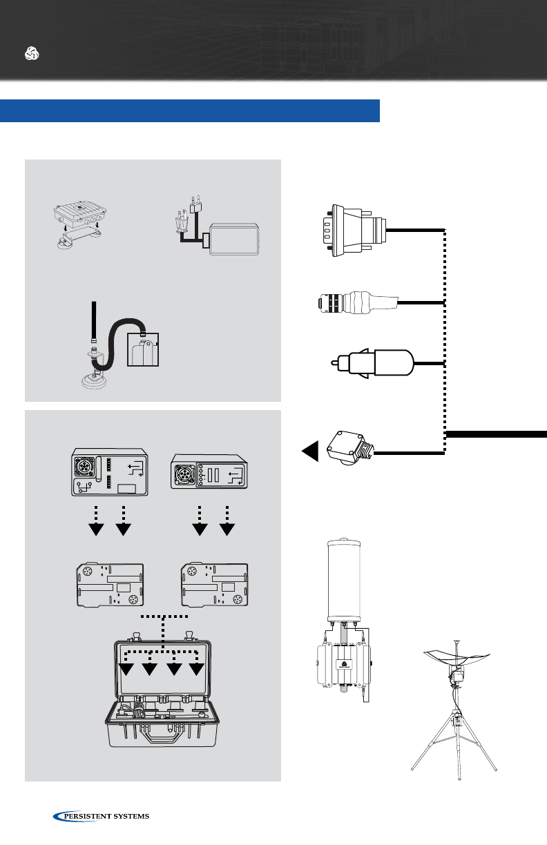
© 2010 - 2015 Persistent Systems, LLC – All Rights Reserved132
QUAD RADIO ROUTER
HARDWARE DETAILS
2.3 GHz
WR-ANT-015
To Power
Antenna
Options
Audio Options
Outdoor PoE Injector
WR-PWR-48V - 60W
Tracking
Antenna System
TRK-KIT-06
Antenna
Connection
Antenna
Connection
4-Pin to 4-Pin
CBL-034
4-Pin to RS-232
CBL-060 (Male)
CBL-061 (Female)
Cable
Options
MOUNTING OPTIONS
POWER OPTIONS
RF Cable
CBL-030
Mag Mount
Bracket
WR-ACC-010
Antenna Magnetic Mount
WR-ACC-013
5 GHz
WR-ANT-026 900 MHz
WR-ANT-085
760 - 780 MHz
WR-ANT-037
4-Pin to Car Adapter
CBL-062
QUAD RADIO
ROUTER
WR-RTR2-XXXXXXXX
Antenna
Connection
4-Pin to BA
CBL-029
110 VAC
220 VAC
110 VAC
220 VAC
Battery
Charger
BAT-05
(fits 4 Battery
Charging Adapters)
BA-2557
BAT-08
BA-2590
BAT-02
0
+
+
-
-
-
100
(2) (5)
(1)
(4)
12V
12V
(3)
SOC
PINS
2-5
SOC
PINS
1-4
SW
(6)
PULL TO REVEAL SMB
DO NOT USE
IN JAVELIN
BATTERY CHARGING ADAPTER
GPS Antenna
WR-ANT-040
(2 foot cable)
WR-ANT-040L
(10 foot cable)
BAT-03BAT-04
PoE Injector
WR-PWR-48V - 60W
(Included free)
Sector Array
Antenna
WR-RTR-XXXXXXXX
Headset &
Push-To-Talk
Adapter
WR-ACC-067
GPS Antenna Options
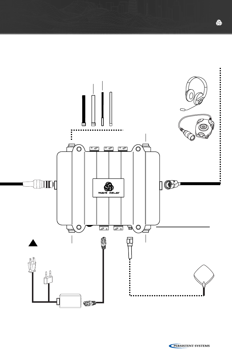
© 2010 - 2015 Persistent Systems, LLC – All Rights Reserved 133
HARDWARE DETAILS
2.3 GHz
WR-ANT-015
To Power
Antenna
Options
Audio Options
Outdoor PoE Injector
WR-PWR-48V - 60W
Tracking
Antenna System
TRK-KIT-06
Antenna
Connection
Antenna
Connection
4-Pin to 4-Pin
CBL-034
4-Pin to RS-232
CBL-060 (Male)
CBL-061 (Female)
Cable
Options
MOUNTING OPTIONS
POWER OPTIONS
RF Cable
CBL-030
Mag Mount
Bracket
WR-ACC-010
Antenna Magnetic Mount
WR-ACC-013
5 GHz
WR-ANT-026 900 MHz
WR-ANT-085
760 - 780 MHz
WR-ANT-037
4-Pin to Car Adapter
CBL-062
QUAD RADIO
ROUTER
WR-RTR2-XXXXXXXX
Antenna
Connection
4-Pin to BA
CBL-029
110 VAC
220 VAC
110 VAC
220 VAC
Battery
Charger
BAT-05
(fits 4 Battery
Charging Adapters)
BA-2557
BAT-08
BA-2590
BAT-02
0
+
+
-
-
-
100
(2) (5)
(1)
(4)
12V
12V
(3)
SOC
PINS
2-5
SOC
PINS
1-4
SW
(6)
PULL TO REVEAL SMB
DO NOT USE
IN JAVELIN
BATTERY CHARGING ADAPTER
GPS Antenna
WR-ANT-040
(2 foot cable)
WR-ANT-040L
(10 foot cable)
BAT-03BAT-04
PoE Injector
WR-PWR-48V - 60W
(Included free)
Sector Array
Antenna
WR-RTR-XXXXXXXX
Headset &
Push-To-Talk
Adapter
WR-ACC-067
GPS Antenna Options
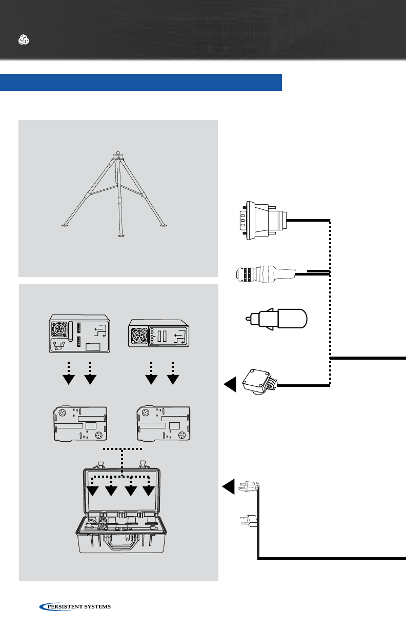
© 2010 - 2015 Persistent Systems, LLC – All Rights Reserved134
SECTOR ARRAY KIT
HARDWARE DETAILS
GPS Antenna
WR-ANT-040
(2 foot cable)
WR-ANT-040L
(10 foot cable)
MOUNTING OPTIONS
POWER OPTIONS
Heavy Duty Tripod
WR-ACC-034 (15 meters)
WR-ACC-028 (7 meters)
Battery
Charger
BAT-05
(fits 4 Battery
Charging Adapters)
BA-2557
BAT-08
BA-2590
BAT-02
0
+
+
-
-
-
100
(2) (5)
(1)
(4)
12V
12V
(3)
SOC
PINS
2-5
SOC
PINS
1-4
SW
(6)
PULL TO REVEAL SMB
DO NOT USE
IN JAVELIN
BATTERY CHARGING ADAPTER
BAT-03BAT-04
Audio Options
CBL-072
(Included free)
CBL-073
(Included free)
To Power
Outdoor
PoE Injector
WR-PWR-48V - 60W GPS Antenna Options
Antenna Options
Sector Array Antenna
WR-RTR-XXXXXXXX
Includes:
Sector Array Antenna
RF Cables
Amplified
Speaker Kit
WR-ACC-079
110 VAC
220 VAC
5 GHz
WR-ANT-067
2.3 GHz
WR-ANT-068
4-Pin to 4-Pin
CBL-034
4-Pin to RS-232
CBL-060 (Male)
CBL-061 (Female)
Cable
Options
4-Pin to Car Adapter
CBL-062
4-Pin to BA
CBL-029
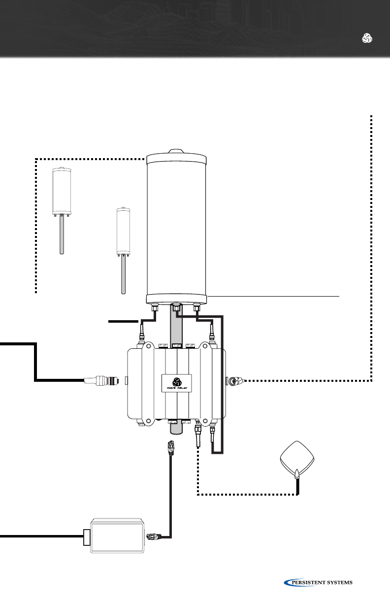
© 2010 - 2015 Persistent Systems, LLC – All Rights Reserved 135
HARDWARE DETAILS
GPS Antenna
WR-ANT-040
(2 foot cable)
WR-ANT-040L
(10 foot cable)
MOUNTING OPTIONS
POWER OPTIONS
Heavy Duty Tripod
WR-ACC-034 (15 meters)
WR-ACC-028 (7 meters)
Battery
Charger
BAT-05
(fits 4 Battery
Charging Adapters)
BA-2557
BAT-08
BA-2590
BAT-02
0
+
+
-
-
-
100
(2) (5)
(1)
(4)
12V
12V
(3)
SOC
PINS
2-5
SOC
PINS
1-4
SW
(6)
PULL TO REVEAL SMB
DO NOT USE
IN JAVELIN
BATTERY CHARGING ADAPTER
BAT-03BAT-04
Audio Options
CBL-072
(Included free)
CBL-073
(Included free)
To Power
Outdoor
PoE Injector
WR-PWR-48V - 60W GPS Antenna Options
Antenna Options
Sector Array Antenna
WR-RTR-XXXXXXXX
Includes:
Sector Array Antenna
RF Cables
Amplified
Speaker Kit
WR-ACC-079
110 VAC
220 VAC
5 GHz
WR-ANT-067
2.3 GHz
WR-ANT-068
4-Pin to 4-Pin
CBL-034
4-Pin to RS-232
CBL-060 (Male)
CBL-061 (Female)
Cable
Options
4-Pin to Car Adapter
CBL-062
4-Pin to BA
CBL-029
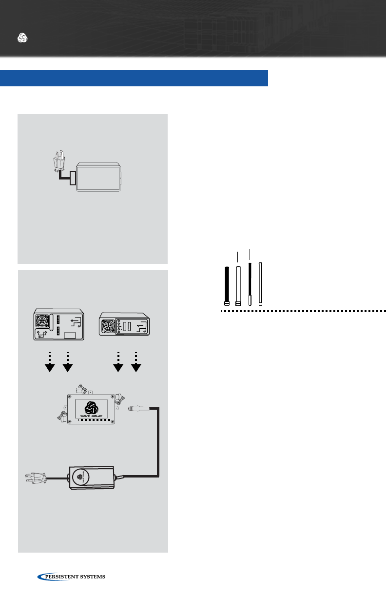
© 2010 - 2015 Persistent Systems, LLC – All Rights Reserved136
TRACKER ANTENNA SYSTEM
HARDWARE DETAILS
2.4GHz
WR-ANT-015
ANTENNA OPTIONS
5GHz
WR-ANT-026
900MHz
WR-ANT-085
760 - 780 MHz
WR-ANT-037
GPS Antenna
WR-ANT-040
WR-ANT040L
Tracking Antenna System
TRK-KIT-06
TRK-01
POWER OPTIONS
BA-2557
BAT-08
BA-2590
BAT-02
0
+
+
-
-
-
100
(2) (5)
(1)
(4)
12V
12V
(3)
SOC
PINS
2-5
SOC
PINS
1-4
SW
(6)
PULL TO REVEAL SMB
DO NOT USE
IN JAVELIN
Power / Communications
Junction Box
TRK-07 (Included)
To 110V - 220V AC Power
Outdoor PoE Injector
WR-PWR-48V - 60W
(US, EU, UK)
Audio Options
Amplified
Speaker Kit
WR-ACC-079
WR-RTR2-XXXXXXXX
with Pole Bracket
(Sold Seperately)
Includes:
- 2.3 Parabolic Grid and Antenna Element
- Tripod
- Pan/Tilt Motor
- Outdoor POE Injector
- Junction Box
- RF Cables
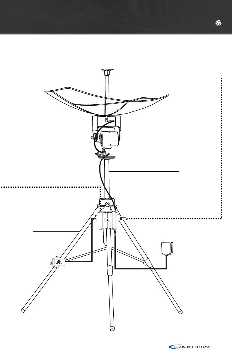
© 2010 - 2015 Persistent Systems, LLC – All Rights Reserved 137
HARDWARE DETAILS
2.4GHz
WR-ANT-015
ANTENNA OPTIONS
5GHz
WR-ANT-026
900MHz
WR-ANT-085
760 - 780 MHz
WR-ANT-037
GPS Antenna
WR-ANT-040
WR-ANT040L
Tracking Antenna System
TRK-KIT-06
TRK-01
POWER OPTIONS
BA-2557
BAT-08
BA-2590
BAT-02
0
+
+
-
-
-
100
(2) (5)
(1)
(4)
12V
12V
(3)
SOC
PINS
2-5
SOC
PINS
1-4
SW
(6)
PULL TO REVEAL SMB
DO NOT USE
IN JAVELIN
Power / Communications
Junction Box
TRK-07 (Included)
To 110V - 220V AC Power
Outdoor PoE Injector
WR-PWR-48V - 60W
(US, EU, UK)
Audio Options
Amplified
Speaker Kit
WR-ACC-079
WR-RTR2-XXXXXXXX
with Pole Bracket
(Sold Seperately)
Includes:
- 2.3 Parabolic Grid and Antenna Element
- Tripod
- Pan/Tilt Motor
- Outdoor POE Injector
- Junction Box
- RF Cables
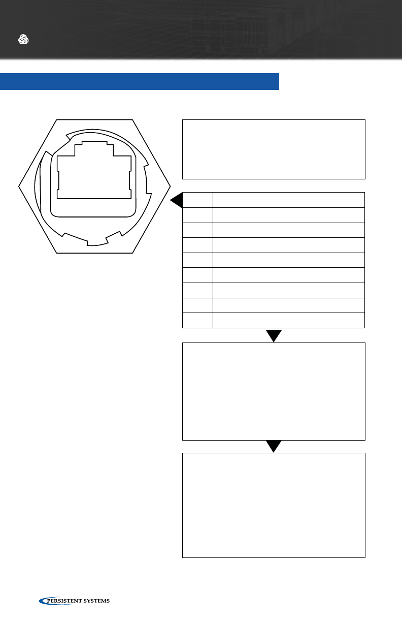
© 2010 - 2015 Persistent Systems, LLC – All Rights Reserved138
ETHERNET 1 PORTS - QUAD RADIO ROUTER
PIN DESCRIPTION
1 Tx(+)
2 Tx(-)
3 Rx(+)
4 PoE Power
5 PoE Power
6 Rx(-)
7 PoE Ground
8 PoE Ground
PoE INFORMATION
Ethernet 1 Accepts 8-48 VDC
Any standard Ethernet cable will carry
power and date
CONNECTION INFORMATION
•Standard CAT5e/RJ45 Ethernet Connection
•Supports Power-Over-Ethernet PoE
•Ethernet 1 Factory Setup IP Address:
10.3.1.254
• Receptacle is rated to IP67 in the unmated
state.
WHAT TO CONNECT
•Standard Ethernet Cable
•Persistent Systems IP67 Rated Ethernet
Cables: 10,15,25, & 100’
•Power-Over-Ethernet(PoE) device included
with every Quad Radio Router System
HARDWARE DETAILS
1 8
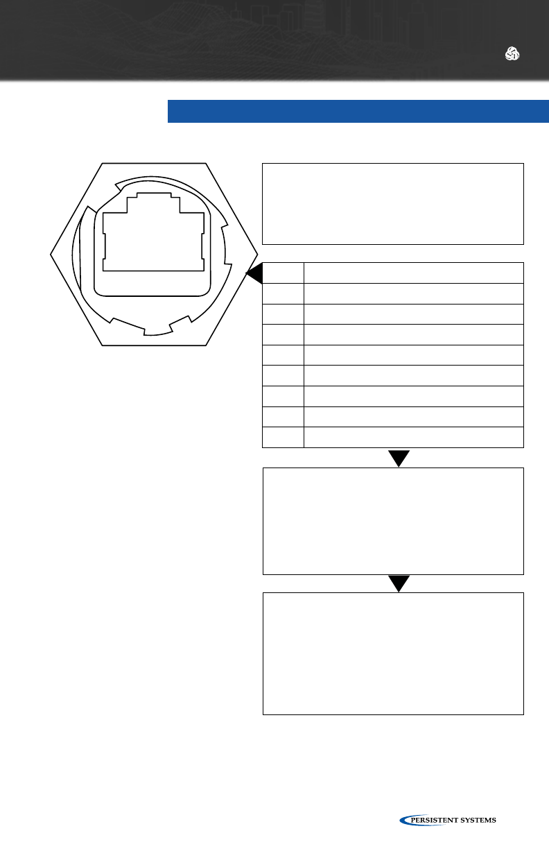
© 2010 - 2015 Persistent Systems, LLC – All Rights Reserved 139
PIN DESCRIPTION
1 Tx(+)
2 Tx(-)
3 Rx(+)
4 N/C
5 N/C
6 Rx(-)
7 N/C
8 N/C
WARNING
Ethernet ports 2-5 do NOT support Power-
Over-Ethernet Functionality
CONNECTION INFORMATION
•Standard CAT5e/RJ45 Ethernet Connection
•Ethernet 2 Factory Setup IP Address:
10.3.2.254
• Receptacle is rated to IP67 in the unmated
state.
WHAT TO CONNECT
•Standard Ethernet Cable
•Persistent Systems IP67 Rated Ethernet
Cables: 10,15,25, & 100’
•Power-Over-Ethernet(PoE) device included
with every Quad Radio Router System
ETHERNET 2 PORTS - QUAD RADIO ROUTER
HARDWARE DETAILS
1 8
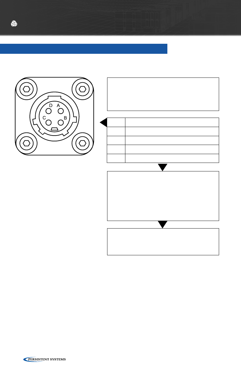
© 2010 - 2015 Persistent Systems, LLC – All Rights Reserved140
HARDWARE DETAILS
PIN DESCRIPTION
A Power In
B Ground
C RS-232 Wave Relay® Tx/Dev Rx
D RS-232 Wave Relay® Rx/Dev Tx
POWER SPECIFICATIONS
Voltage Range: 8-48 VDC
Maximum Current: 5 Amps
CONNECTOR INFORMATION
•IP67 Rated
•Offers auxiliary power option and serial I/O
•Mating Plug: CONN-046
WHAT TO CONNECT
CBL-029, 062, 069, 034, 060, 061
AUXILIARY POWER - QUAD RADIO ROUTER
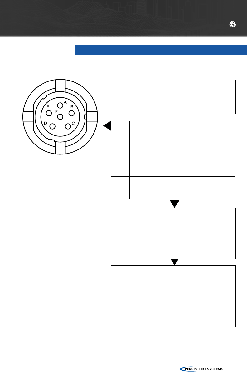
© 2010 - 2015 Persistent Systems, LLC – All Rights Reserved 141
HARDWARE DETAILS
PIN DESCRIPTION
A Audio Ground
B Audio Input (microphone)
C Audio Push-To-Talk
D Audio Output (speaker)
E RS-232 Wave Relay® Tx/Dev Rx
F RS-232 Wave Relay® Rx/Dev Tx
or
+5 V Accessory Power
NOTE
The PTT Audio connections on the Quad
Radio Router and the MPU4 are NOT wired
identically.
CONNECTOR INFORMATION
•NATO U-283/U Standard Wiring for PTT
Devices
•IP67 Rated
WHAT TO CONNECT
WR-ACC-067, WR-ACC-079
PTT AUDIO = QUAD RADIO ROUTER

© 2010 - 2015 Persistent Systems, LLC – All Rights Reserved142
REGULATORY INFORMATION
REGULATORY INFORMATION
The following notes refer to these part numbers: WR-MPU4-04, WR-MPU3-04,
WR-MPU3-0409, and WR-RTR2-04040909.
THIS DEVICE COMPLIES WITH PART 15 OF THE FCC RULES. OPERATION IS SUB-
JECT TO THE FOLLOWING TWO CONDITIONS:
(1) THIS DEVICE MAY NOT CAUSE HARMFUL INTERFERENCE, AND
(2) THIS DEVICE MUST ACCEPT ANY INTERFERENCE RECEIVED, INCLUDING
INTERFERENCE THAT MAY CAUSE UNDESIRED OPERATION.
NOTE: THE MANUFACTURER IS NOT RESPONSIBLE FOR ANY RADIO OR TV
INTERFERENCE CAUSED BY UNAUTHORIZED MODIFICATIONS TO THIS
EQUIPMENT. SUCH MODIFICATIONS COULD VOID THE USER’S AUTHORITY
TO OPERATE THE EQUIPMENT.
NOTE II: This equipment has been tested and found to comply with the limits for
a Class A digital device, pursuant to Part 15 of the FCC Rules. These limits are
designed to provide reasonable protection against harmful interference when
the equipment is operated in a commercial environment. This equipment gen-
erates, uses, and can radiate radio frequency energy and, if not installed and
used in accordance with the instruction manual, may cause harmful interference
to radio communications. Operation of this equipment in a residential area is
likely to cause harmful interference in which case the user will be required to
correct the interference at their own expense.

© 2010 - 2015 Persistent Systems, LLC – All Rights Reserved 143
REGULATORY INFORMATION

303 Fifth Avenue Suite 306
New York, NY 10016
www.persistentsystems.com
03EN009 (English) VERSION 3.1
03EN009
WAVE RELAY®
USER MANUAL