Unigen UGWC821R NEMO BLUETOOTH RADIO MODULE User Manual NEMO Datasheet UGWC621RSMA133
Unigen Corporation NEMO BLUETOOTH RADIO MODULE NEMO Datasheet UGWC621RSMA133
Unigen >
Contents
- 1. user manual
- 2. user manual design guidelines
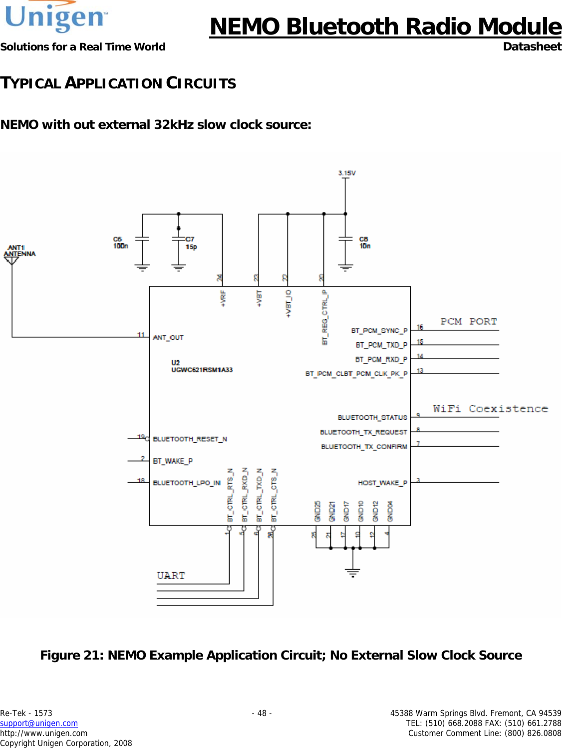
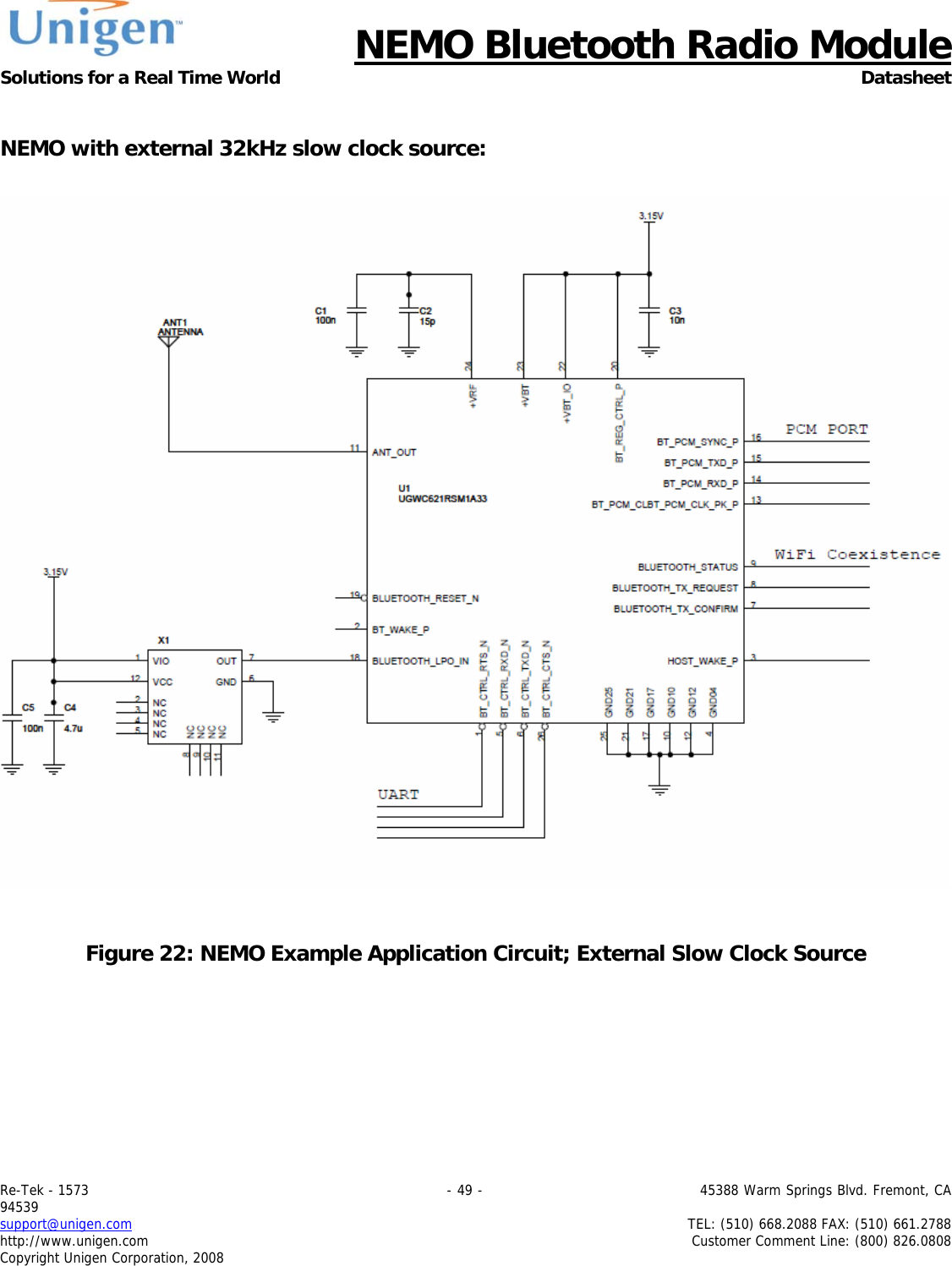
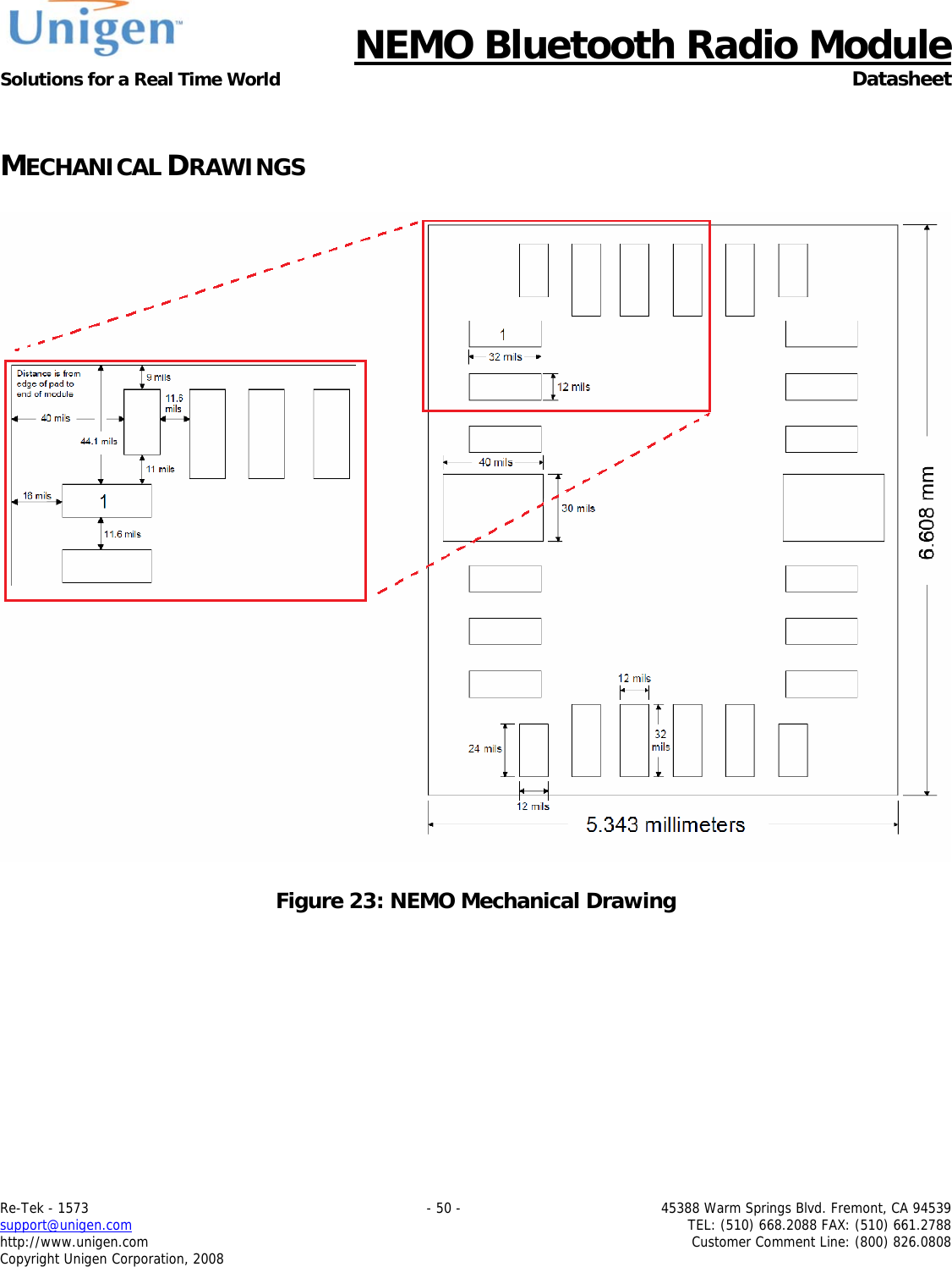
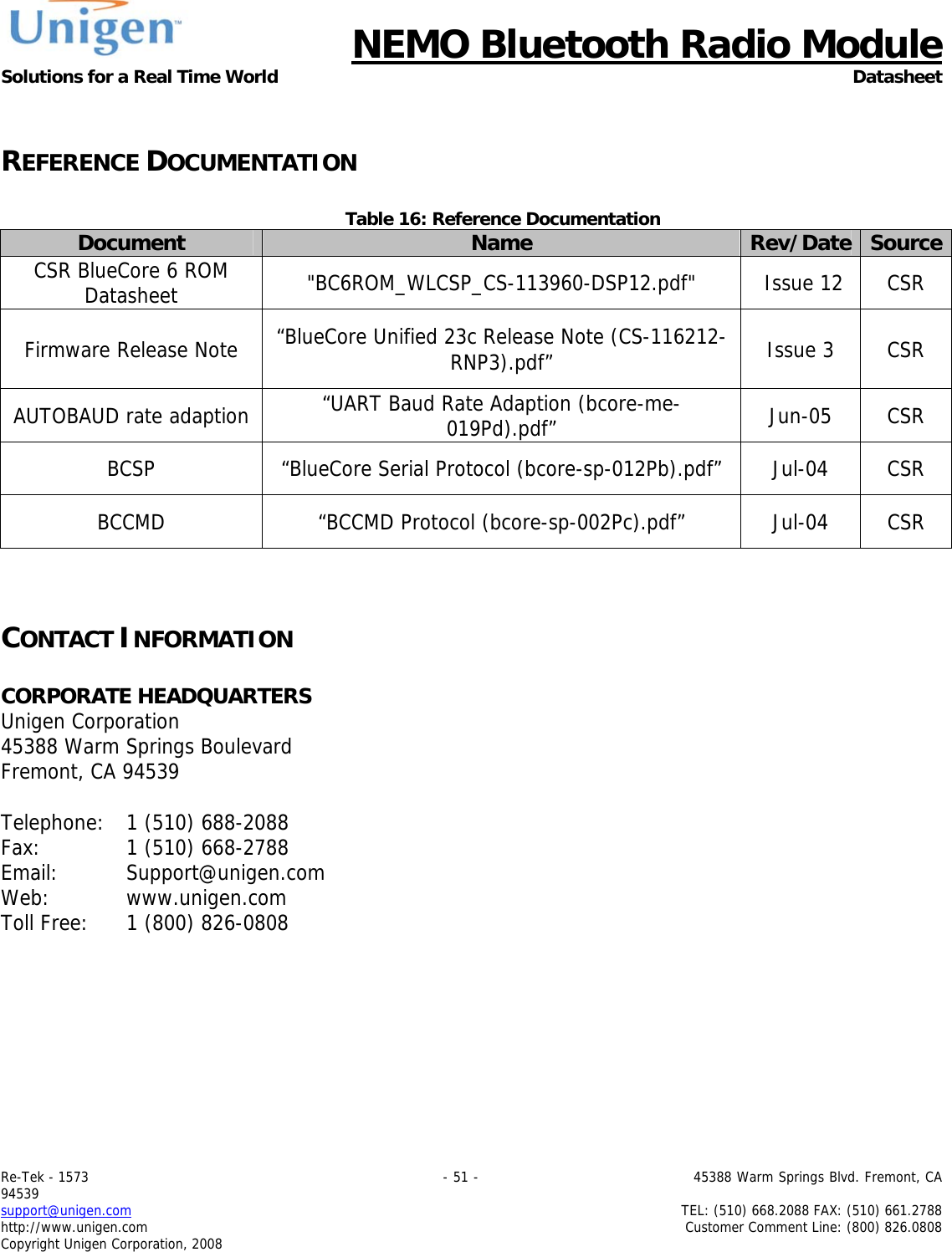
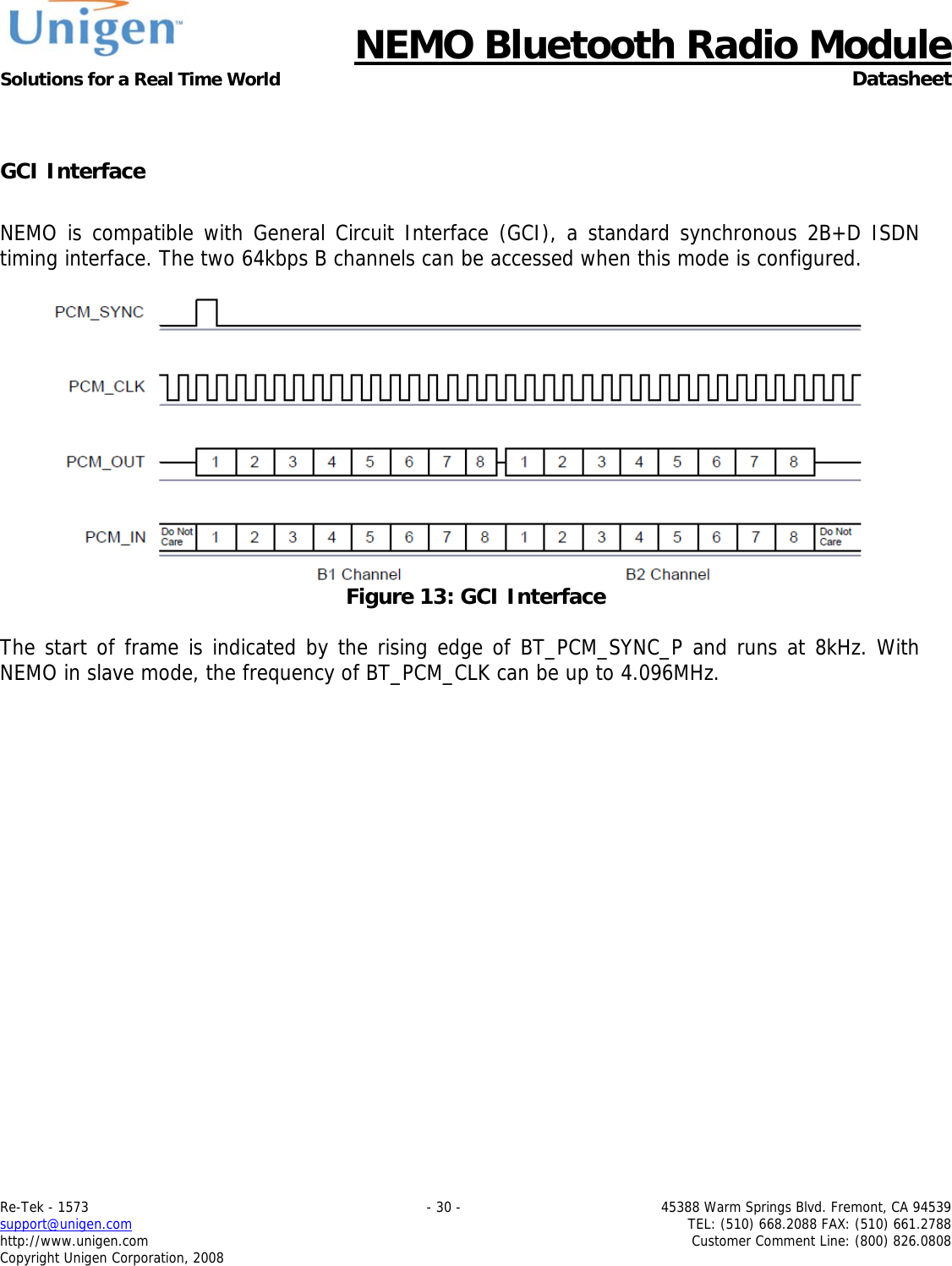
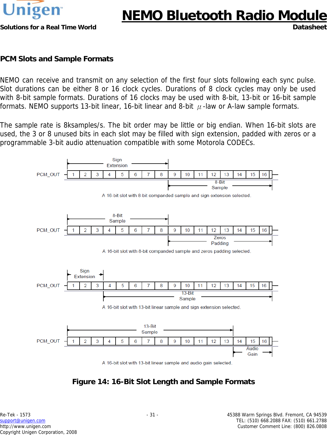
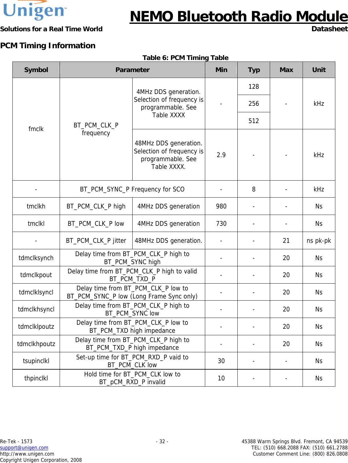
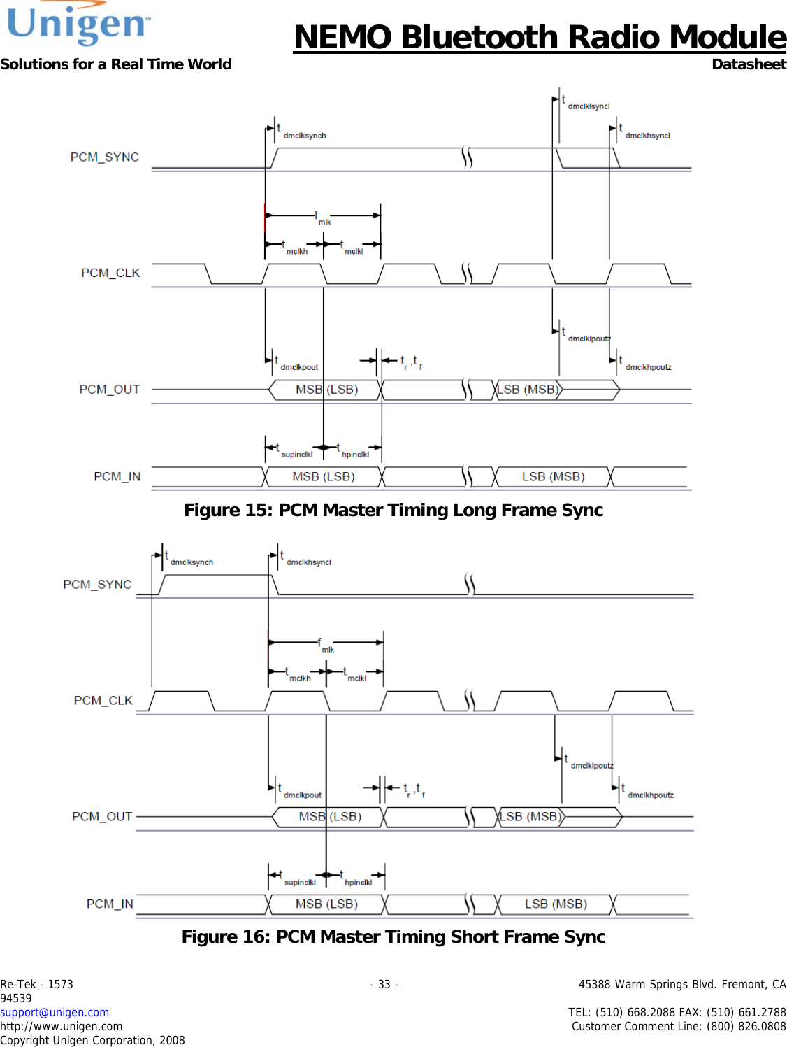
user manual
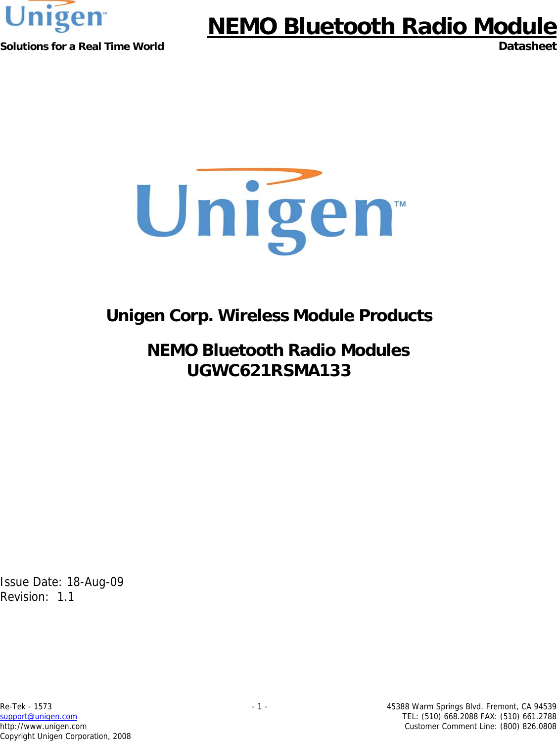
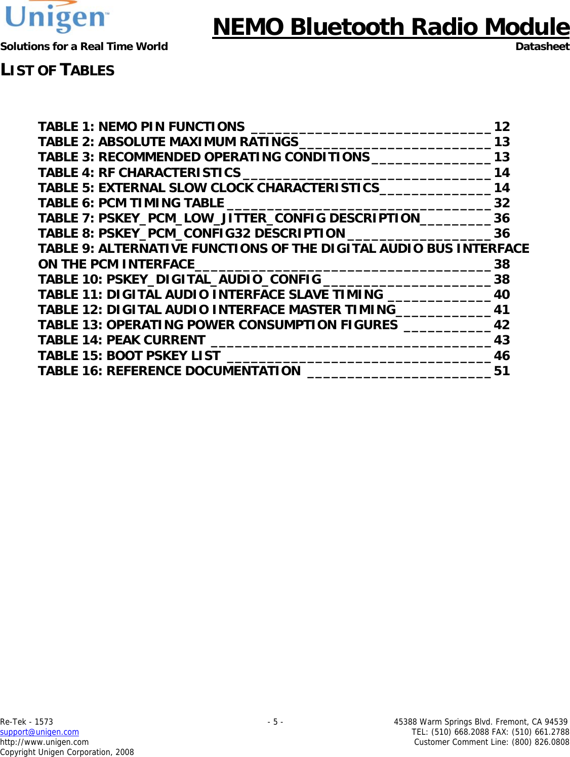
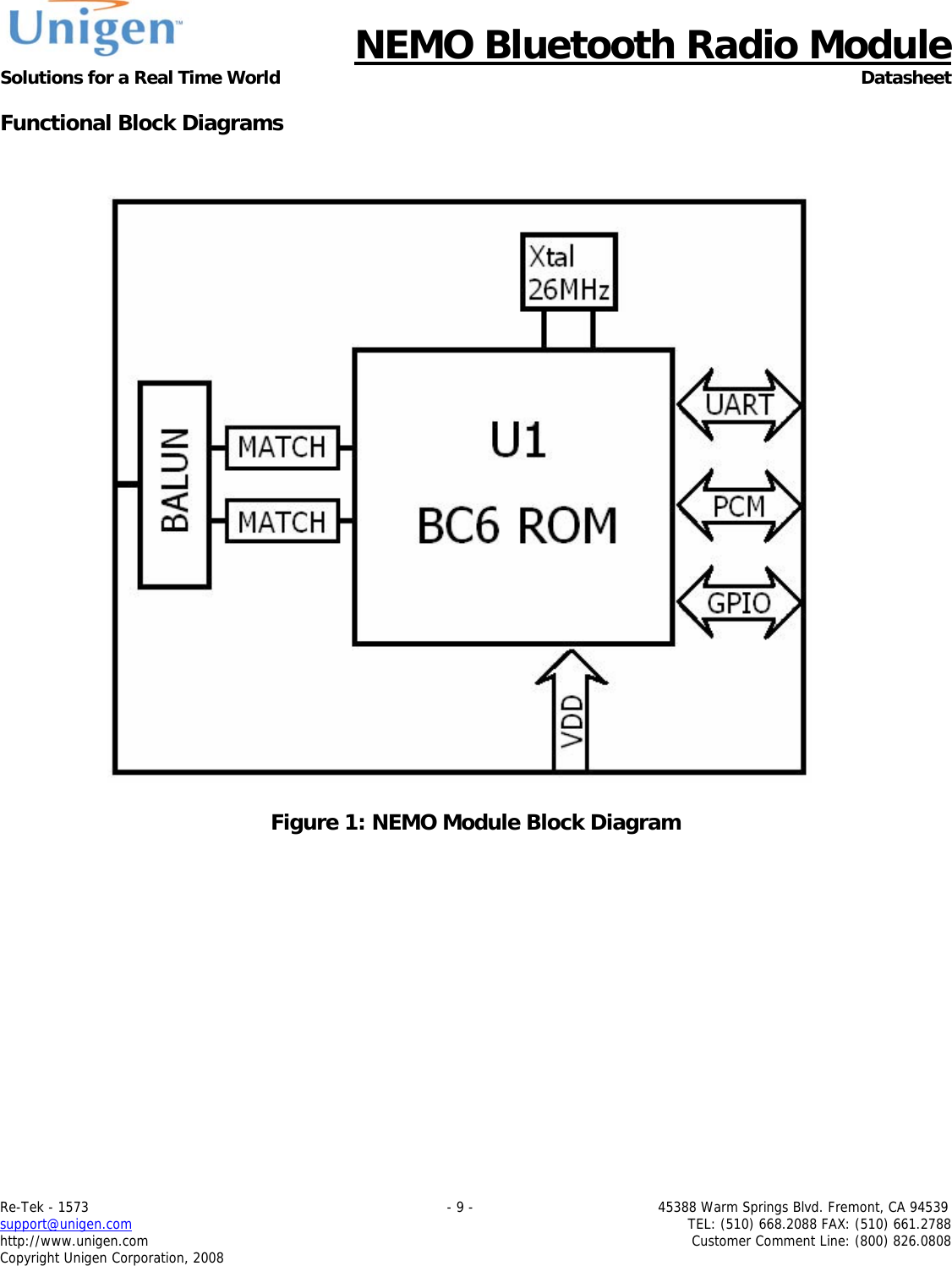

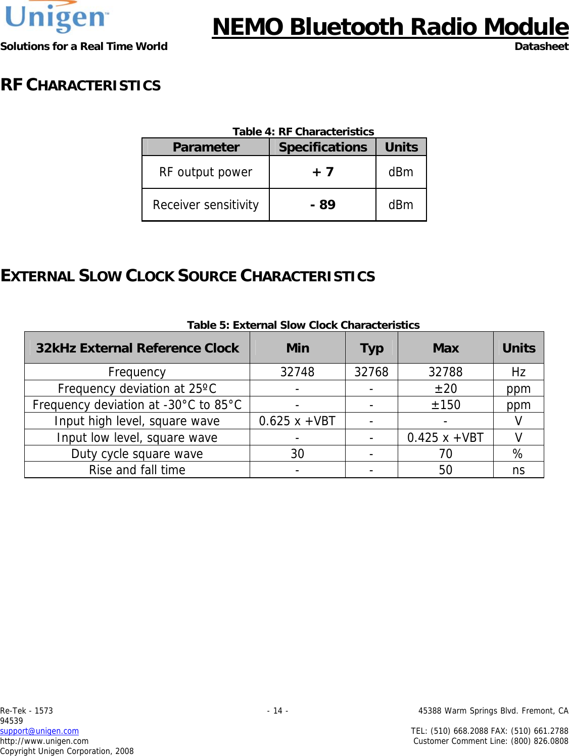
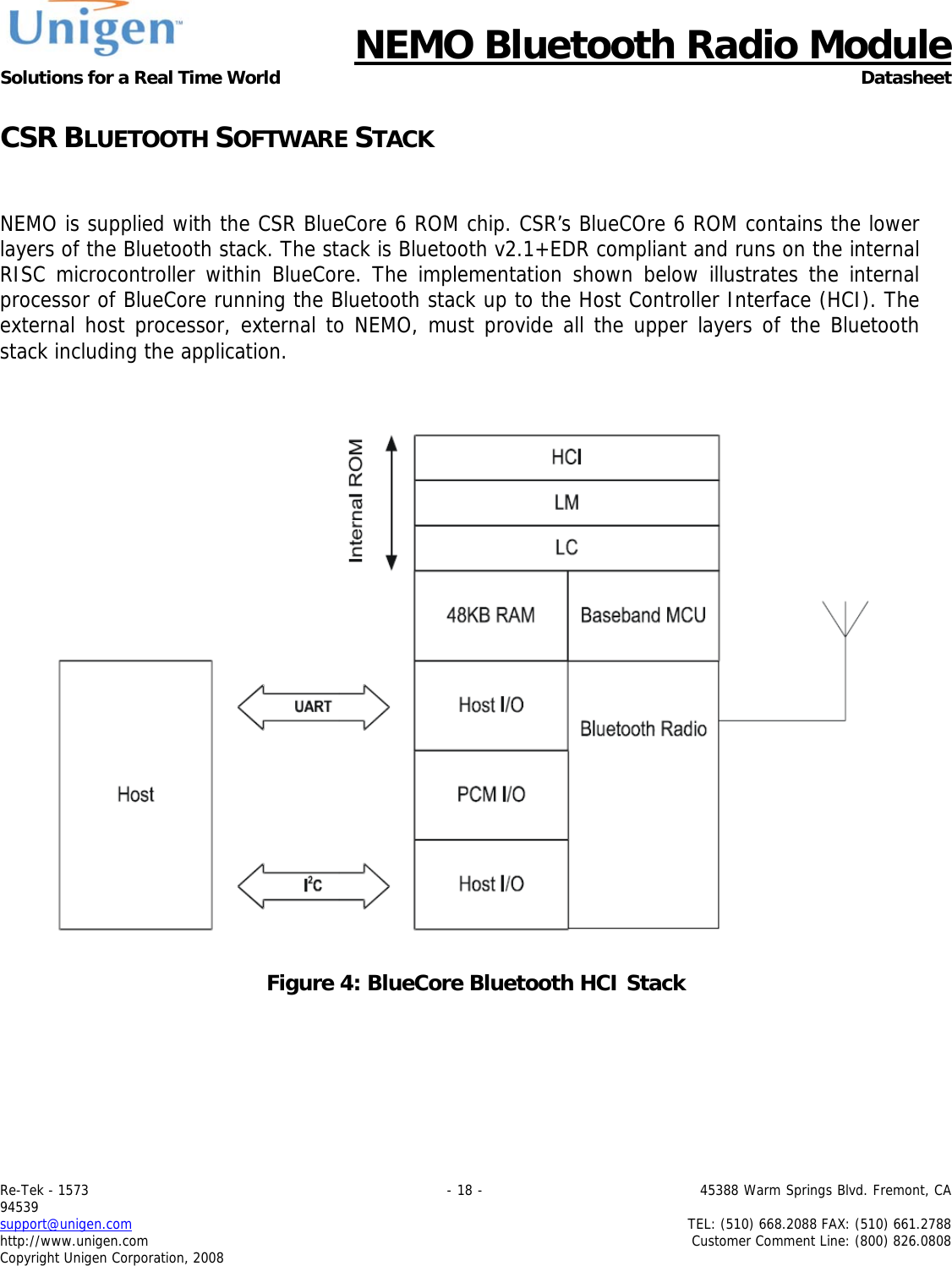
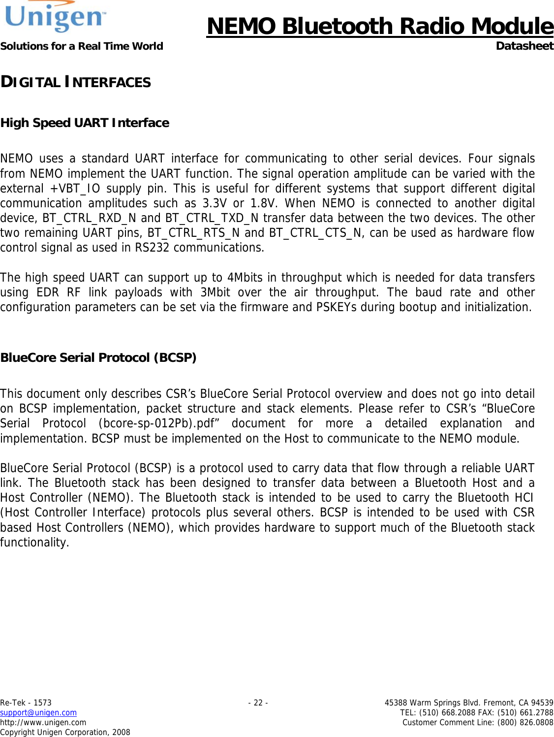
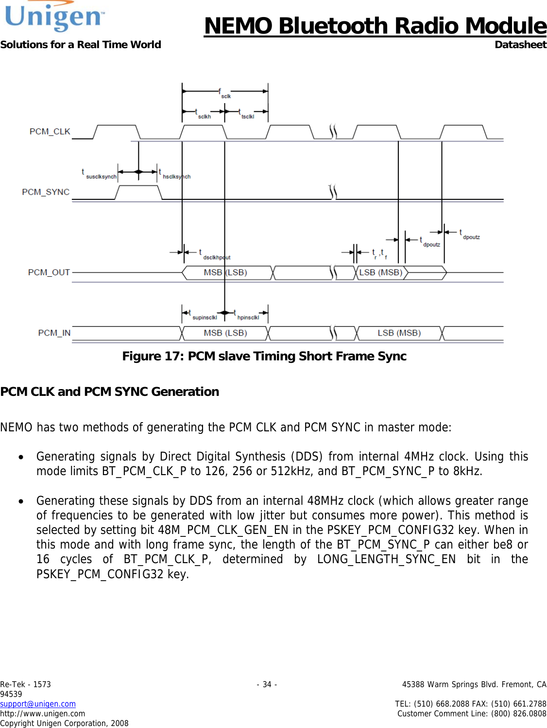
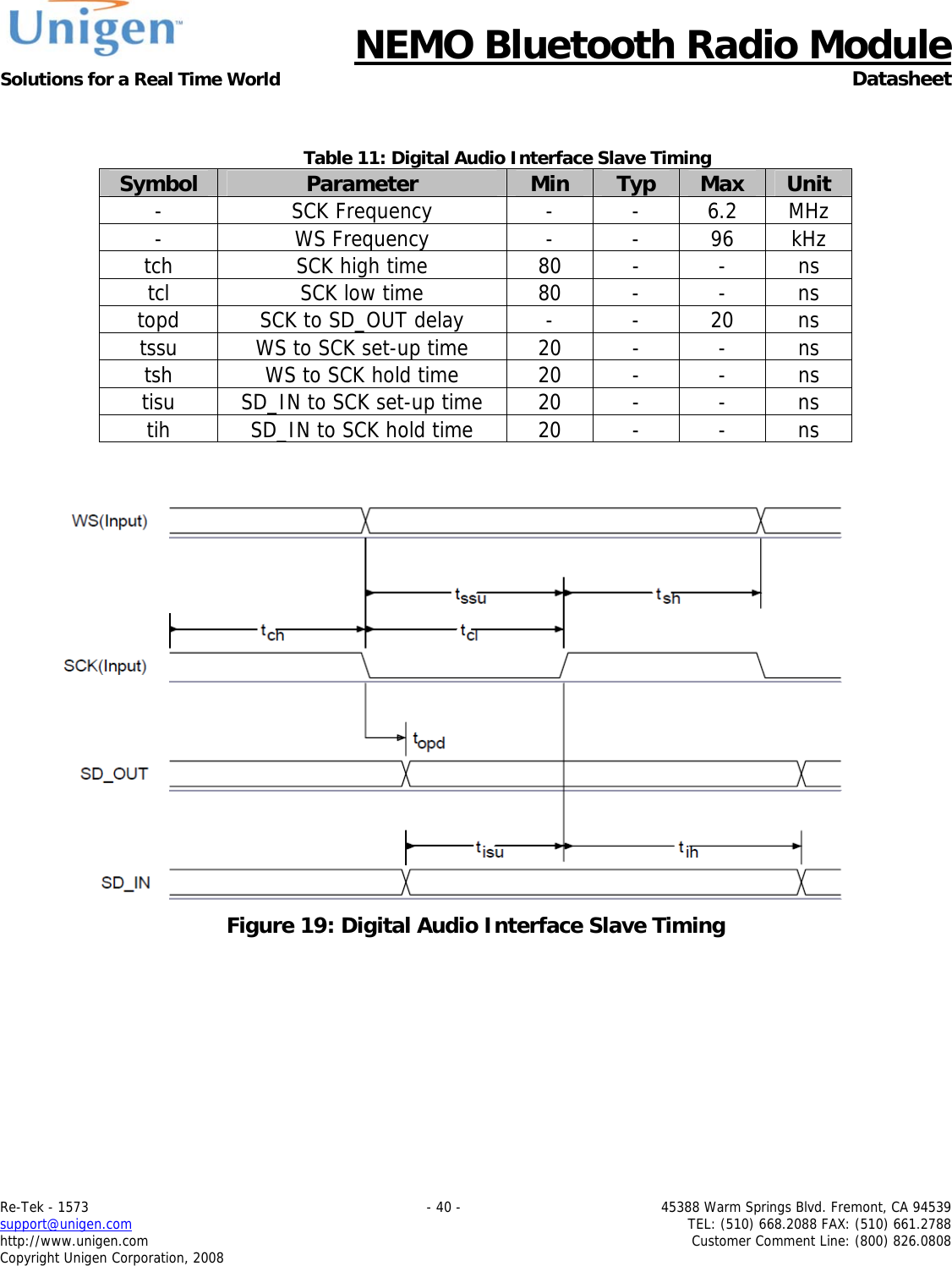
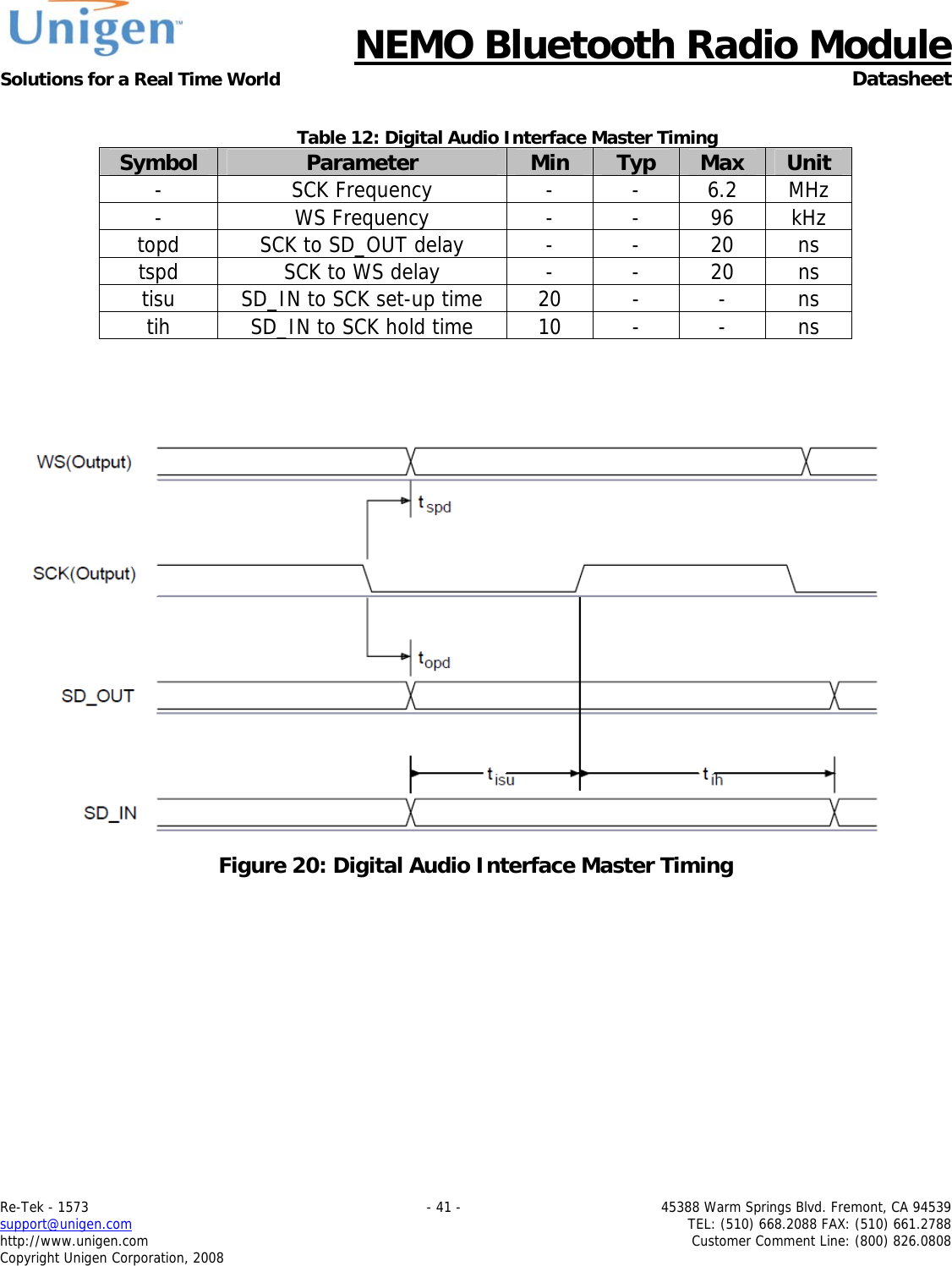
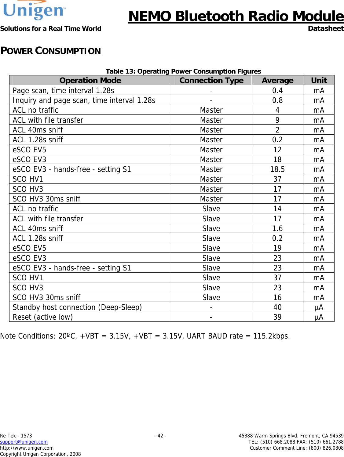
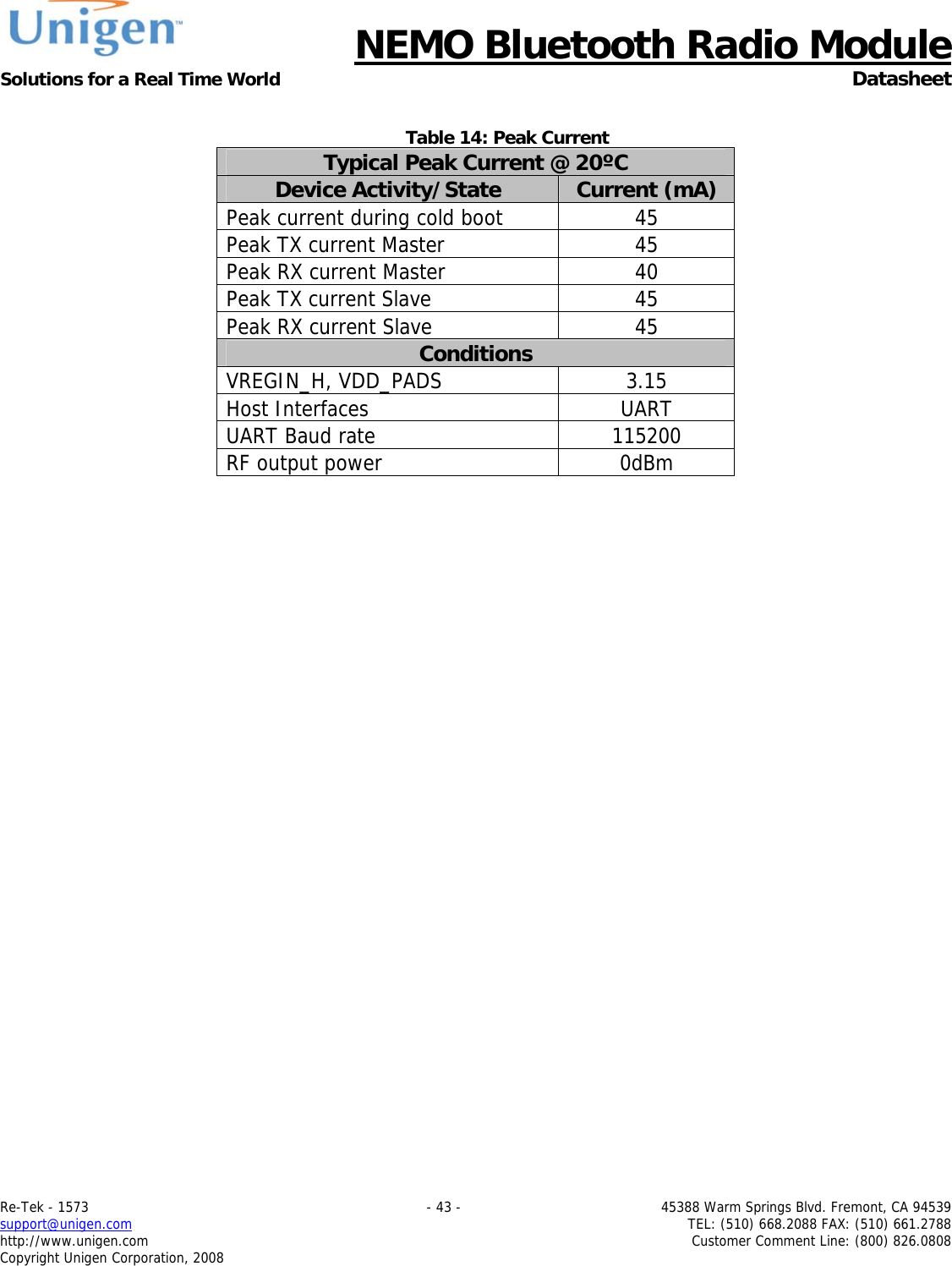
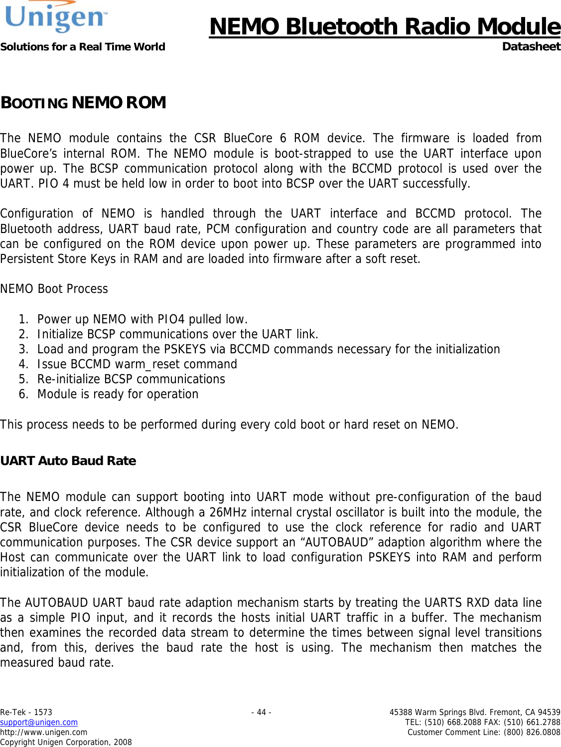
![NEMO Bluetooth Radio Module Solutions for a Real Time World Datasheet Re-Tek - 1573 - 36 - 45388 Warm Springs Blvd. Fremont, CA 94539 support@unigen.com TEL: (510) 668.2088 FAX: (510) 661.2788 http://www.unigen.com Customer Comment Line: (800) 826.0808 Copyright Unigen Corporation, 2008 Table 7: PSKEY_PCM_LOW_JITTER_CONFIG Description Name Bit Position Description CNT_LIMIT [12:0] Sets the PCM CLK counter limit CNT_RATE [23:16] Sets the PCM CLK count rate SYNC_LIMIT [31:24] Sets the PCM SYNC division relative to PCM CLK Table 8: PSKEY_PCM_CONFIG32 Description Name Bit Position Description 0 Set to 0 SLAVE_MODE_EN 1 0 = Master mode with internal generation of the BT_PCM_CLK_P and BT_PCM_SYNC_P. 1 = Slave mode requiring externally generated PCM CLK and the PCM SYNC signals. SHORT_SYNC_EN 2 0 = Long Frame Sync mode (rising edge indicates start of frame). 1 = Short Frame Sync mode (falling edge indicates start of frame). 3 Set to 0 SIGN_EXTENDED_EN 4 0 = Padding of 8 or 13-bit voice sample into a 16-bit slot by inserting extra LSBs. When padding is selected with 13-bit voice sample, the 3 padding bits are the audio gain setting; with 8-bit sample the 8 padding bits are zeroes. 1 = Sign-extension. LSB_FIRST_EN 5 0 = MSB first of transmit and receive voice samples. 1 = LSB first of transmit and receive voice samples. TX_TRISTATE_EN 6 0 = Drive PCM_OUT continuously. 1 = Tri-state BT_PCM_TXD_P immediately after falling edge of BT_PCM_CLK_P in the last bit of an active slot, assuming the next slot is not active. TX_TRISTATE_RISING_EDGE_EN 7 0 = Tri-state BT_PCM_TXD_P immediately after falling edge of BT_PCM_CLK_P in last bit of an active slot, assuming the next slot is also not active. 1 = Tri-state BT_PCM_TXD after rising edge of BT_PCM_CLK_P.](https://usermanual.wiki/Unigen/UGWC821R.user-manual/User-Guide-1722660-Page-36.png)
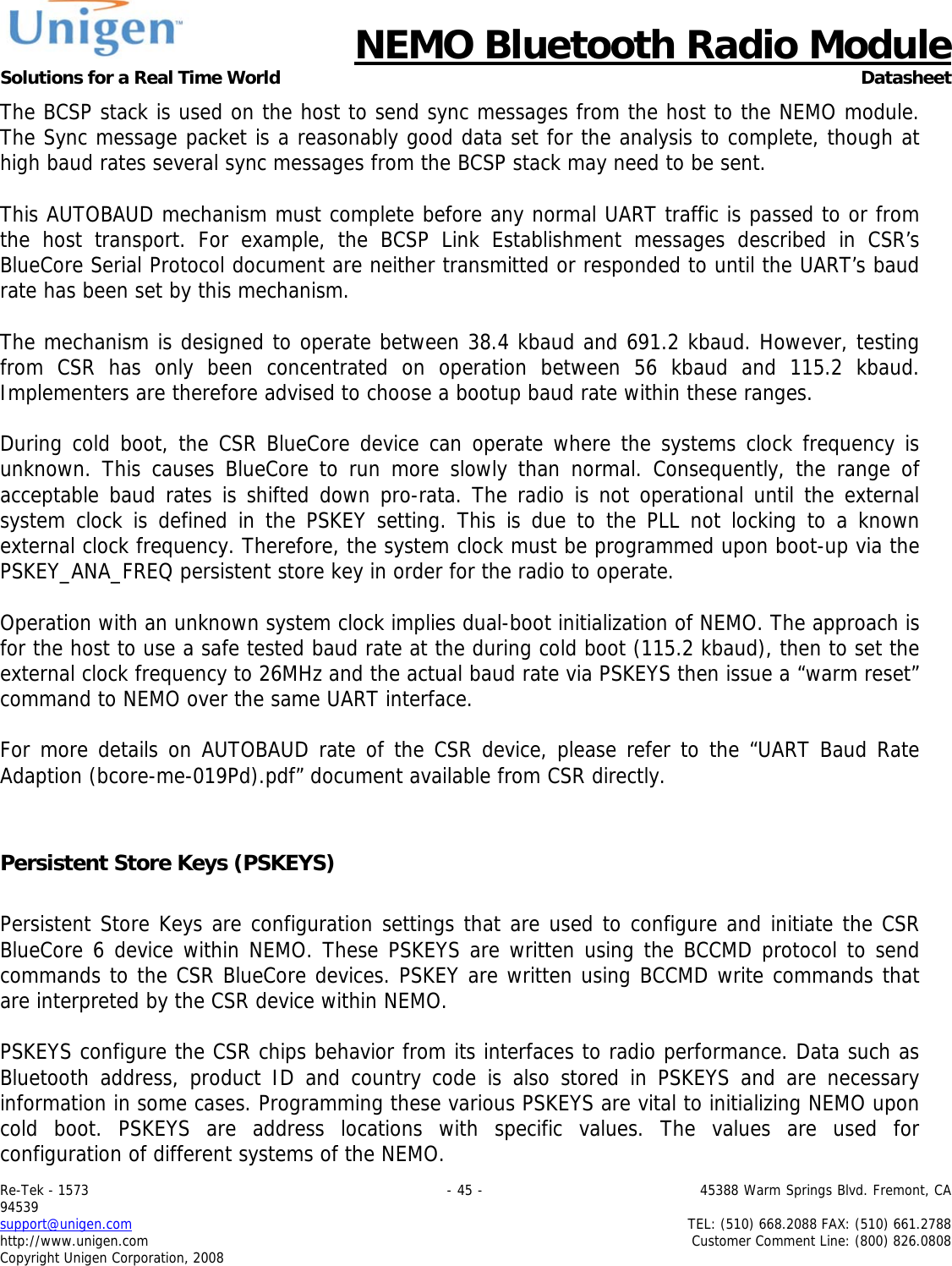
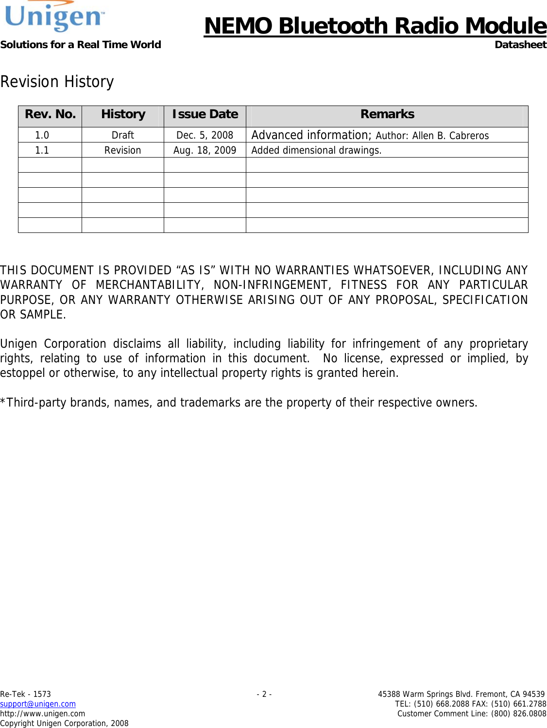
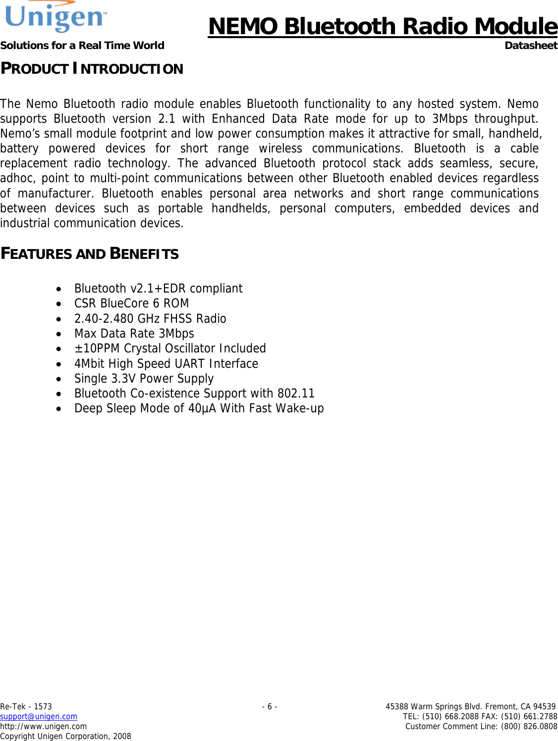
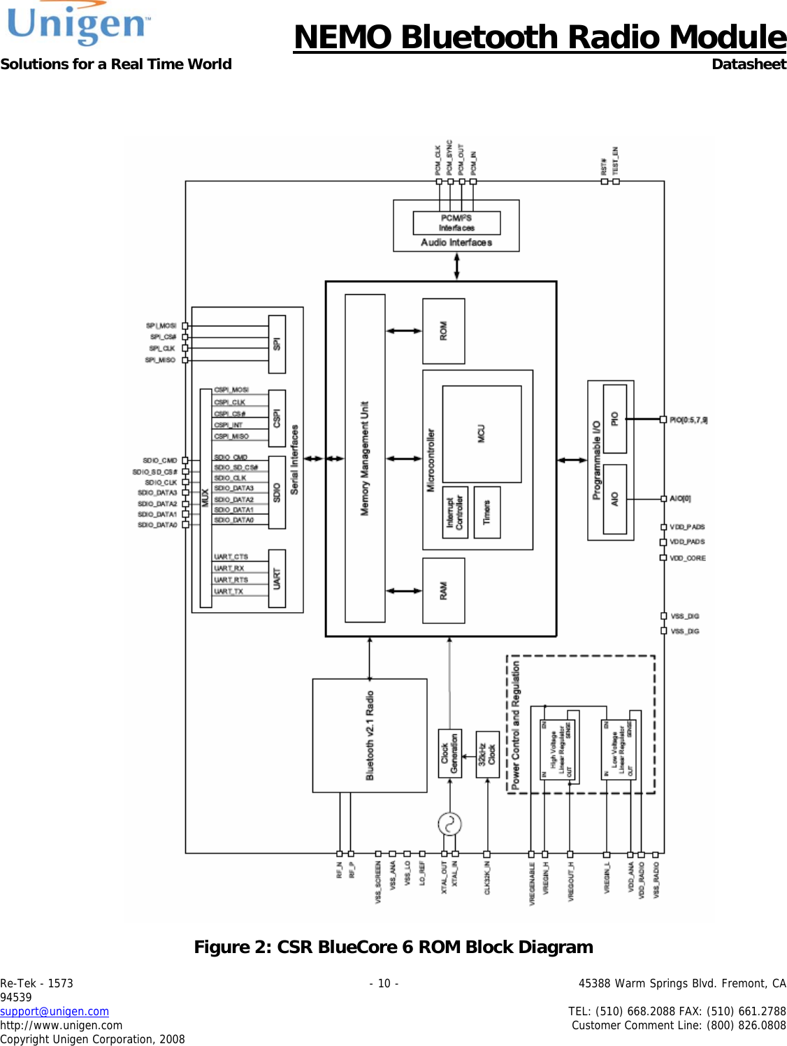
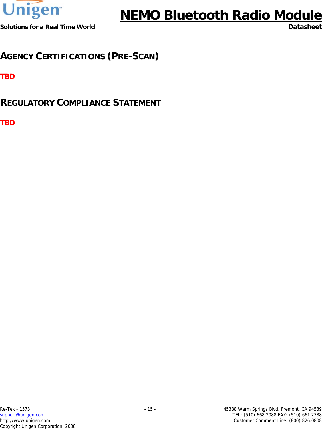
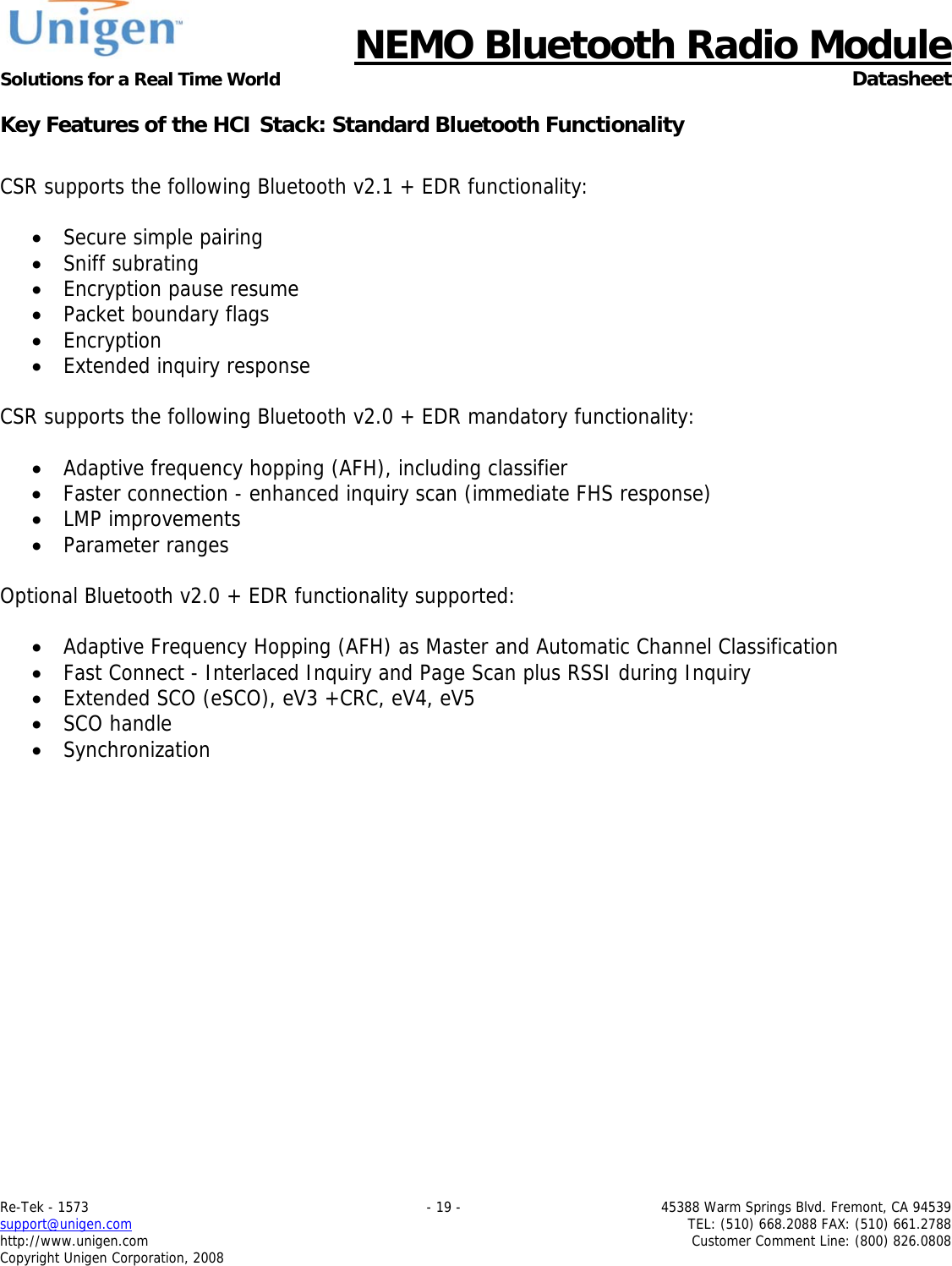
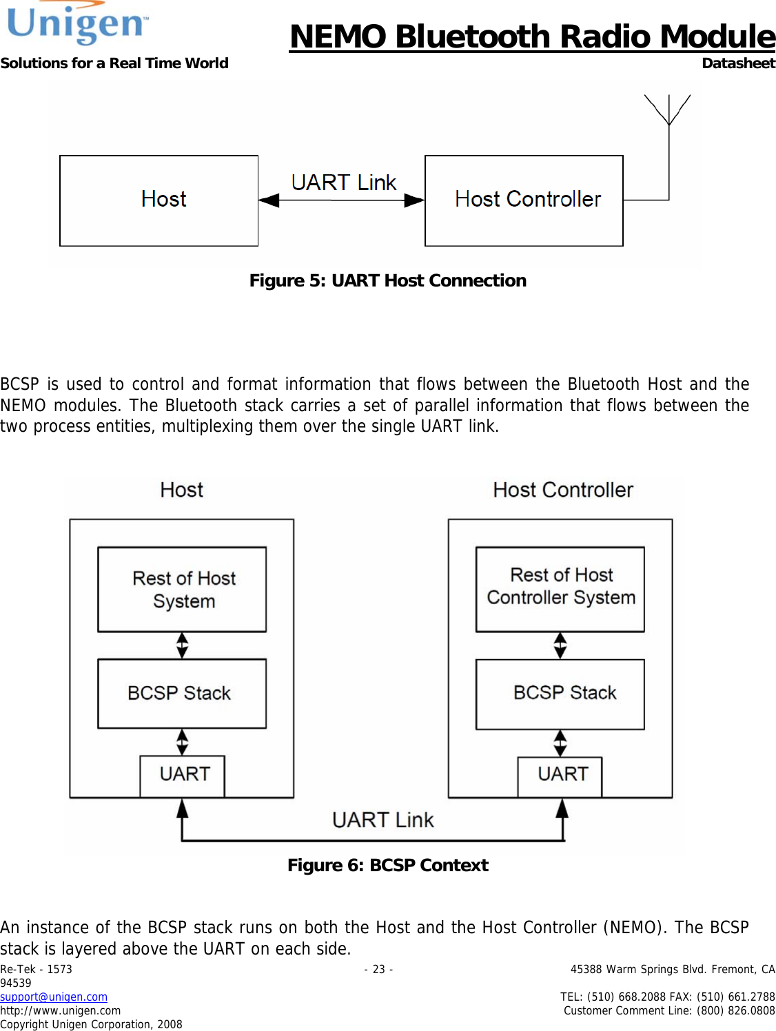
![NEMO Bluetooth Radio Module Solutions for a Real Time World Datasheet Re-Tek - 1573 - 37 - 45388 Warm Springs Blvd. Fremont, CA 94539 support@unigen.com TEL: (510) 668.2088 FAX: (510) 661.2788 http://www.unigen.com Customer Comment Line: (800) 826.0808 Copyright Unigen Corporation, 2008 SYNC_SUPPRESS_EN 8 0 = enable PCM_SYNC output when master. 1 = suppress PCM_SYNC while keeping PCM_CLK running. Some CODECS use this to enter a low power state. GCI_MODE_EN 9 1 = enable GCI mode. MUTE_EN 10 1 = force BT_PCM_TXD_P to 0. 48M_PCM_CLK_GEN_EN 11 0 = set PCM_CLK and PCM_SYNC generation via DDS from internal 4MHz clock. 1 = set PCM_CLK and PCM_SYNC generation via DDS from internal 48MHz clock. LONG_LENGTH_SYNC_EN 12 0 = set PCM_SYNC length to 8 PCM_CLK cycles. 1 = set length to 16 PCM_CLK cycles. Only applies for long frame sync and with 48M_PCM_CLK_GEN_EN set to 1. PCM_SYNC_MULT 13 0 = Sync limit = SYNC_LIMIT x 8. 1 = SYNC_LIMIT. [20:16] Set to 0b00000 MASTER_CLK_RATE [22:21] Selects 128 (0b01), 256 (0b00), 512 (0b10) kHz BT_PCM_CLK+P frequency when master and 48M_PCM_CLK_GEN_EN (bit 11) is low. ACTIVE_SLOT [26:23] Default is 0001. Ignored by firmware. SAMPLE_FORMAT [28:27] Selects between 13 (0b00), 16 (0b01), 8 (0b10) bit sample with 16-cycle slot duration or 8 (0b11) bit sample with 8-cycle slot duration.](https://usermanual.wiki/Unigen/UGWC821R.user-manual/User-Guide-1722660-Page-37.png)
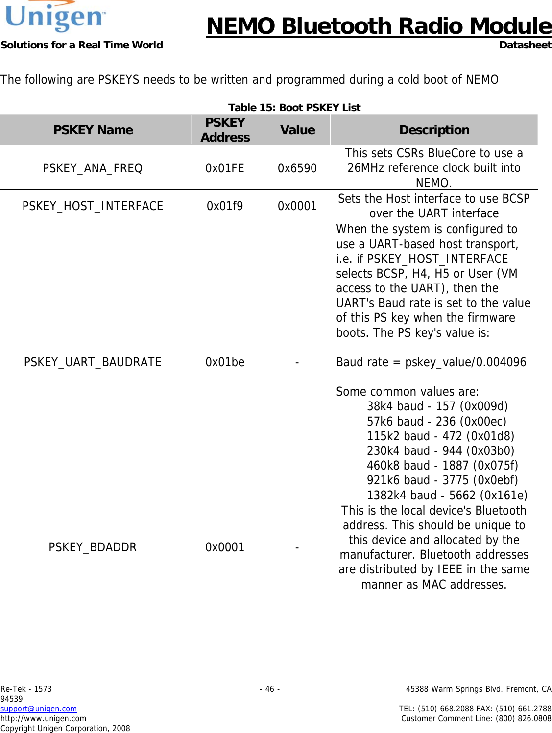
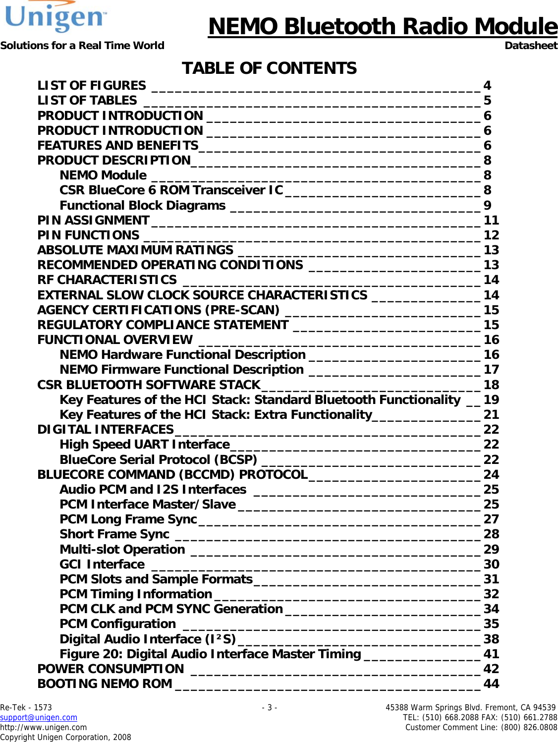
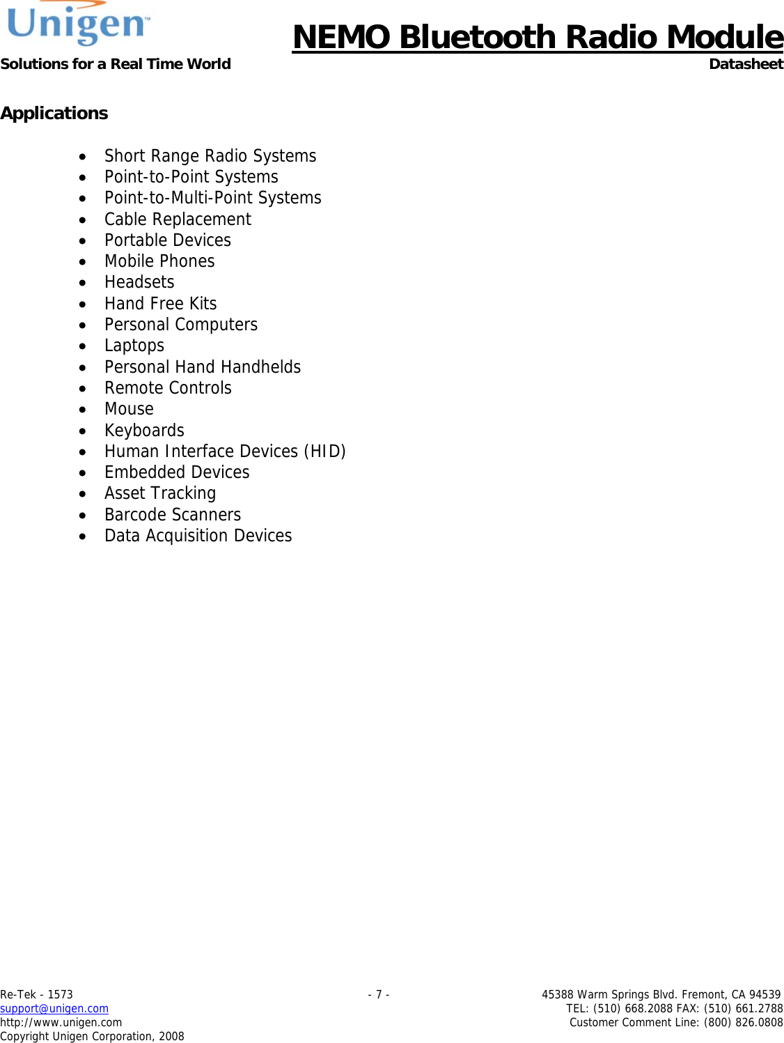
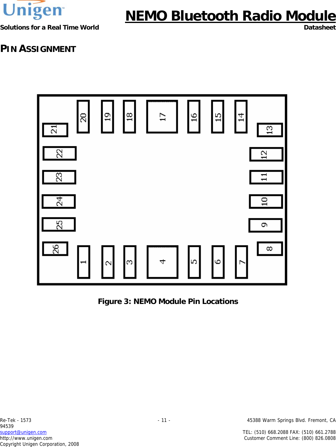
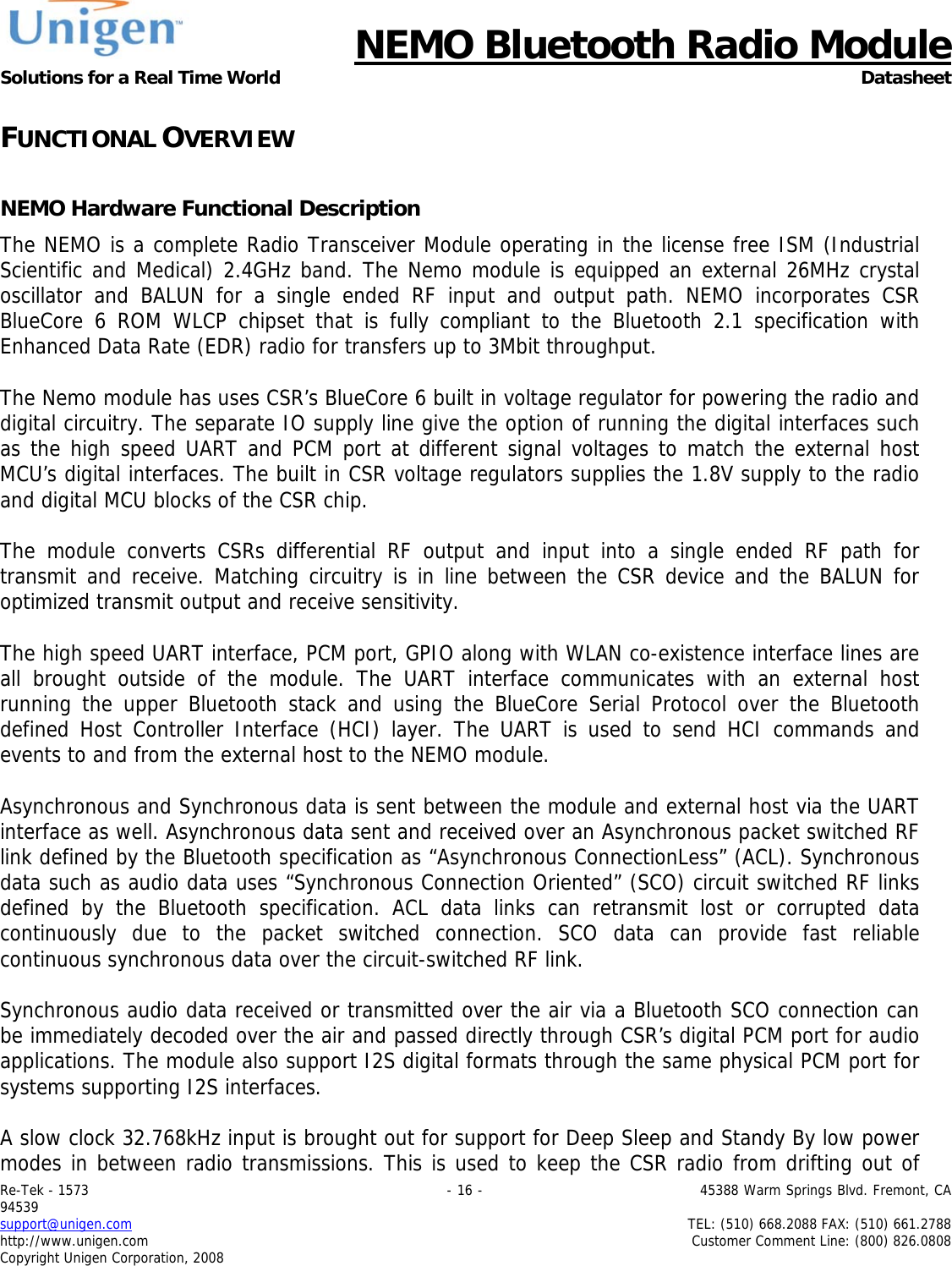
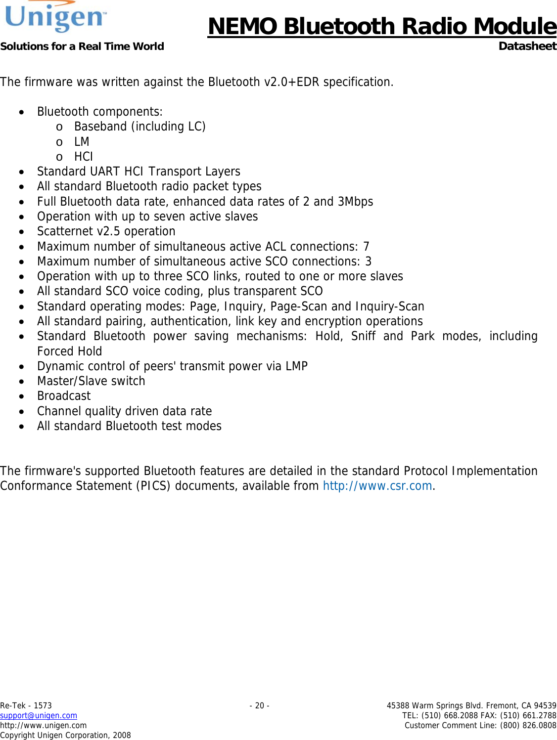
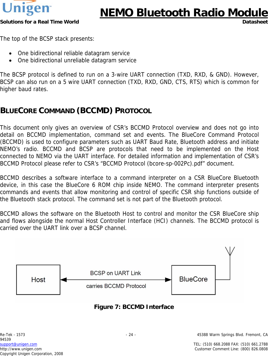
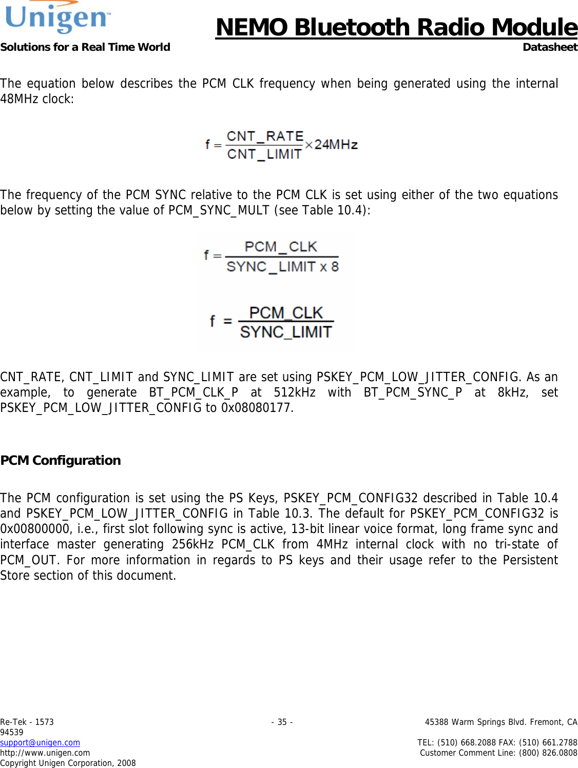
![NEMO Bluetooth Radio Module Solutions for a Real Time World Datasheet Re-Tek - 1573 - 38 - 45388 Warm Springs Blvd. Fremont, CA 94539 support@unigen.com TEL: (510) 668.2088 FAX: (510) 661.2788 http://www.unigen.com Customer Comment Line: (800) 826.0808 Copyright Unigen Corporation, 2008 Digital Audio Interface (I²S) The digital audio interface supports the industry standard formats for I²S, left-justified (LJ) or right-justified (RJ). The interface shares the same pins as the PCM interface, which means each audio bus is mutually exclusive in its usage. Table 7 lists these alternative functions. Table 9: Alternative Functions of the Digital Audio Bus Interface on the PCM Interface PCM Interface I²S Interface BT_PCM_TXD_P SD_OUT BT_PCM_RXD_P SD_IN BT_PCM_SYNC_P WS BT_PCM_CLK_P SCK Table 8 describes the values for the PS Key (PSKEY_DIGITAL_AUDIO_CONFIG) that is used to set-up the digital audio interface. For example, to configure an I²S interface with 16-bit SD data set PSKEY_DIGITAL_CONFIG to 0x0406. Table 10: PSKEY_DIGITAL_AUDIO_CONFIG Bit Mask Name Description D[0] 0x0001 CONFIG_JUSTIFY_FORMAT 0 for left justified, 1 for right justified. D[1] 0x0002 CONFIG_LEFT_JUSTIFY_DELAY For left justified formats: 0 is MSB of SD data occurs in the first SCLK period following WS transition. 1 is MSB of SD data occurs in the second SCLK period. D[2] 0x0004 CONFIG_CHANNEL_POLARITY For 0, SD data is left channel when WS is high. For 1 SD data is right channel. D[3] 0x0008 CONFIG_AUDIO_ATTEN_EN For 0, 17 bit SD data is rounded down to 16 bits. For 1, the audio attenuation defined in CONFIG_AUDIO_ATTEN is applied over 24 bits with saturated rounding. Requires CONFIG_16_BIT_CROP_EN to be 0. D[7:4] 0x00F0 CONFIG_AUDIO_ATTEN Attenuation in 6 dB steps.](https://usermanual.wiki/Unigen/UGWC821R.user-manual/User-Guide-1722660-Page-38.png)
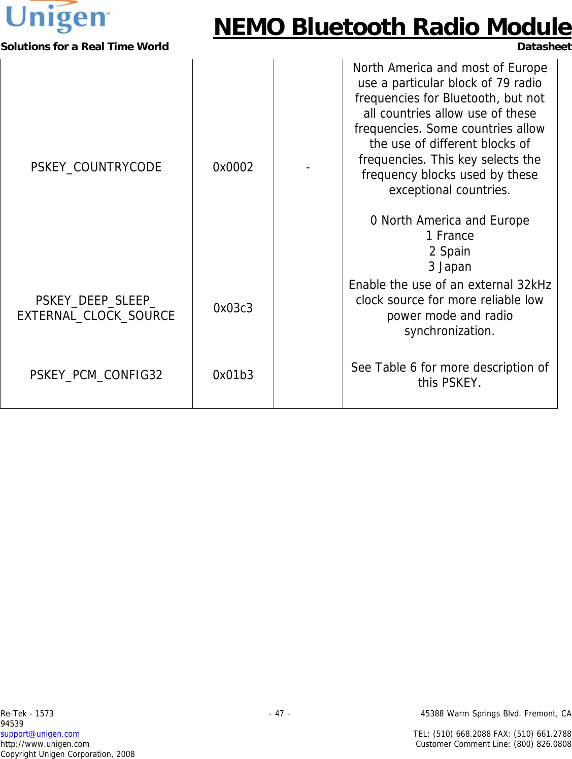
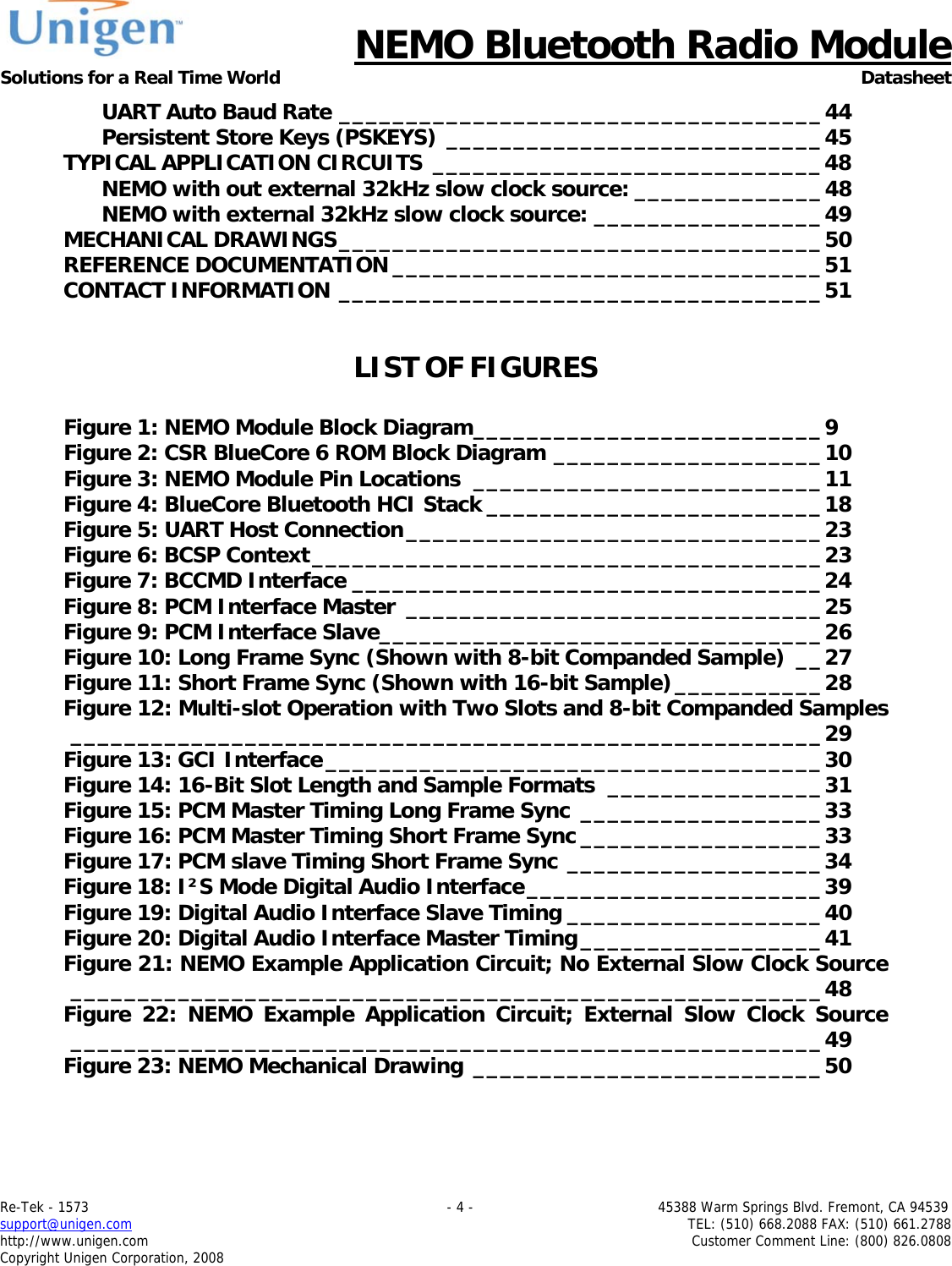
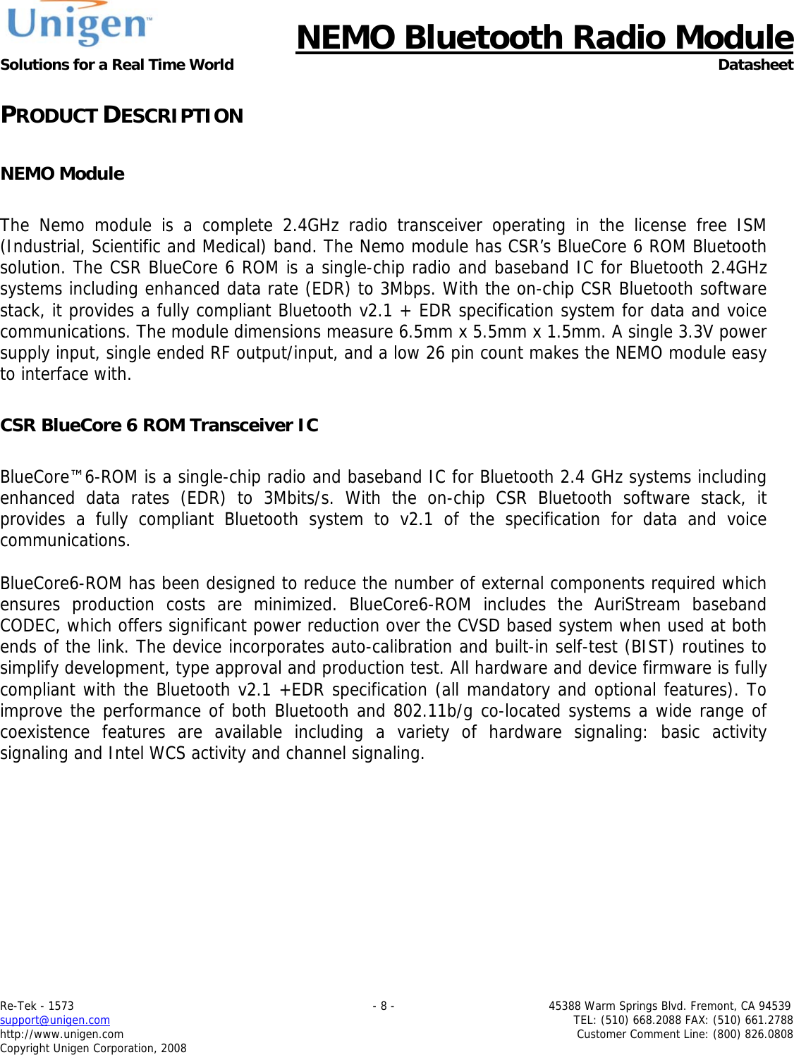
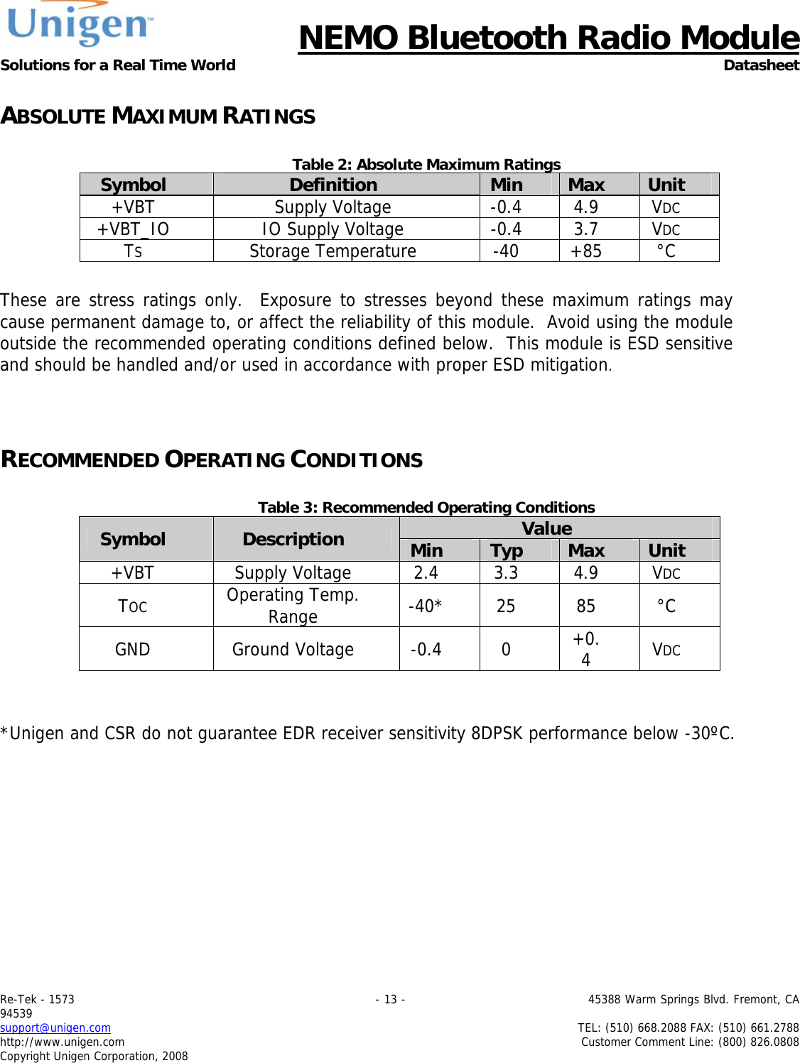
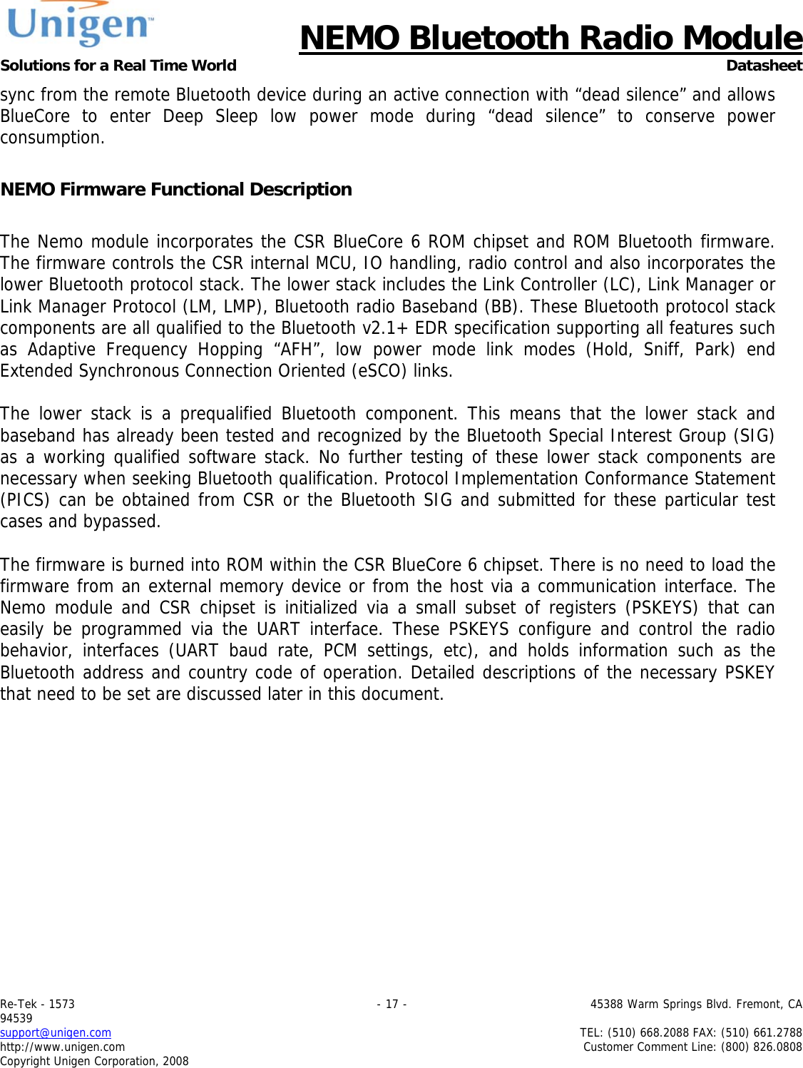
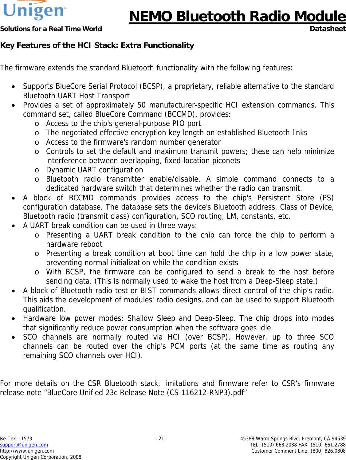
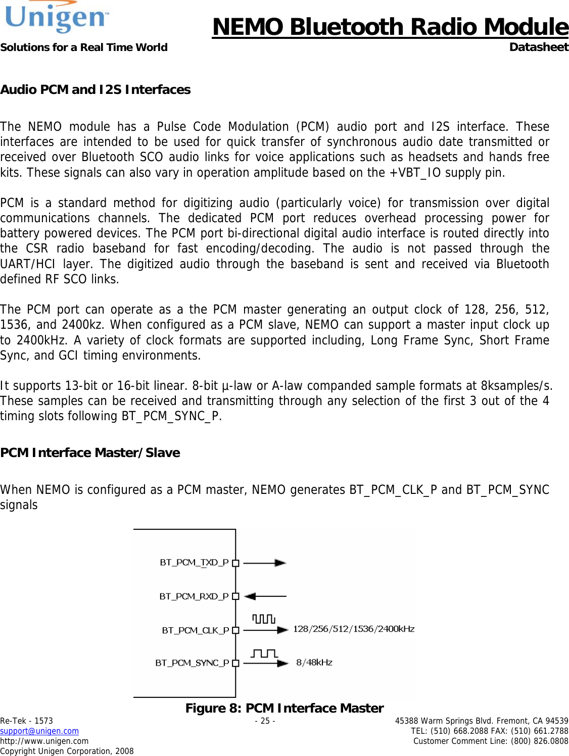
![NEMO Bluetooth Radio Module Solutions for a Real Time World Datasheet Re-Tek - 1573 - 39 - 45388 Warm Springs Blvd. Fremont, CA 94539 support@unigen.com TEL: (510) 668.2088 FAX: (510) 661.2788 http://www.unigen.com Customer Comment Line: (800) 826.0808 Copyright Unigen Corporation, 2008 D[9:8] 0x0300 CONFIG_JUSTIFY_RESOLUTION Resolution of data on SD_IN, 00=16 bit, 01=20 bit, 10=24 bit, 11=Reserved. This is required for right justified format and with left justified LSB first. D[10] 0x0400 CONFIG_16_BIT_CROP_EN For 0, 17 bit SD_IN data is rounded down to 16 bits. For 1 only the most significant 16 bits of data are received. Figure 18: I²S Mode Digital Audio Interface](https://usermanual.wiki/Unigen/UGWC821R.user-manual/User-Guide-1722660-Page-39.png)