Universal Electronics 4012 ViewSonic Tweety RF Remote Control User Manual users manual
Universal Electronics Inc ViewSonic Tweety RF Remote Control users manual
UserManual.wiki
>
Universal Electronics
>
4012 User Manual
users manual
Navigation menu
Upload a User Manual
Namespaces
Wiki Guide
HTML
PDF
Info
Views
User Manual
Discussion / Help
Navigation
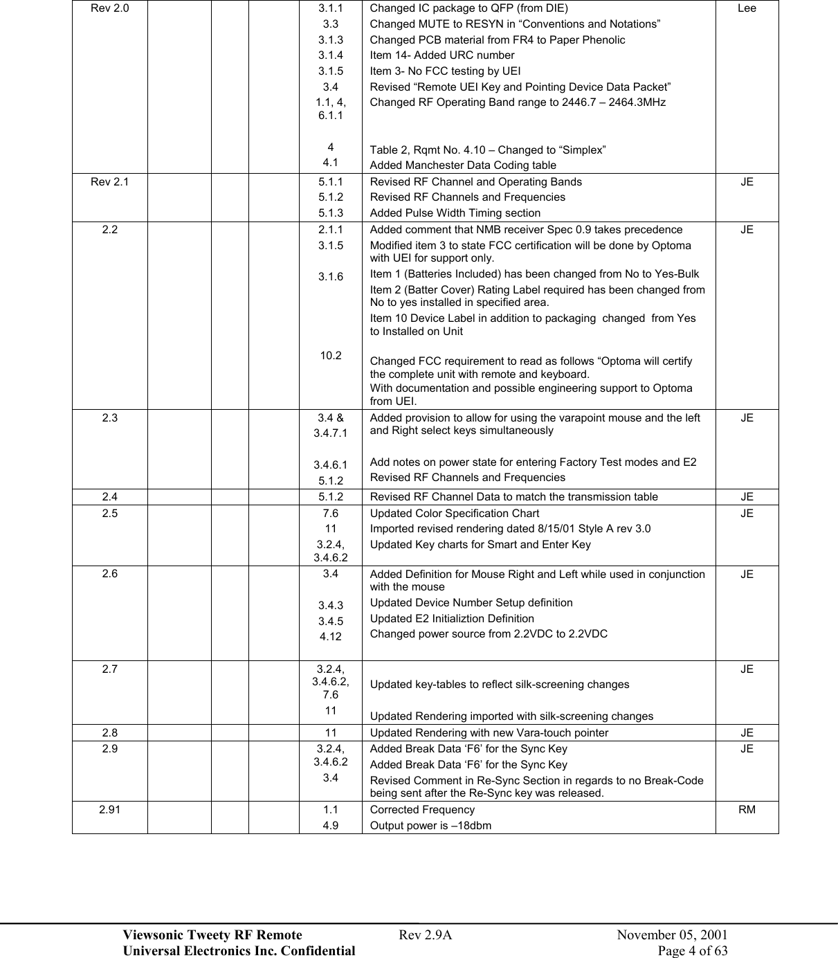
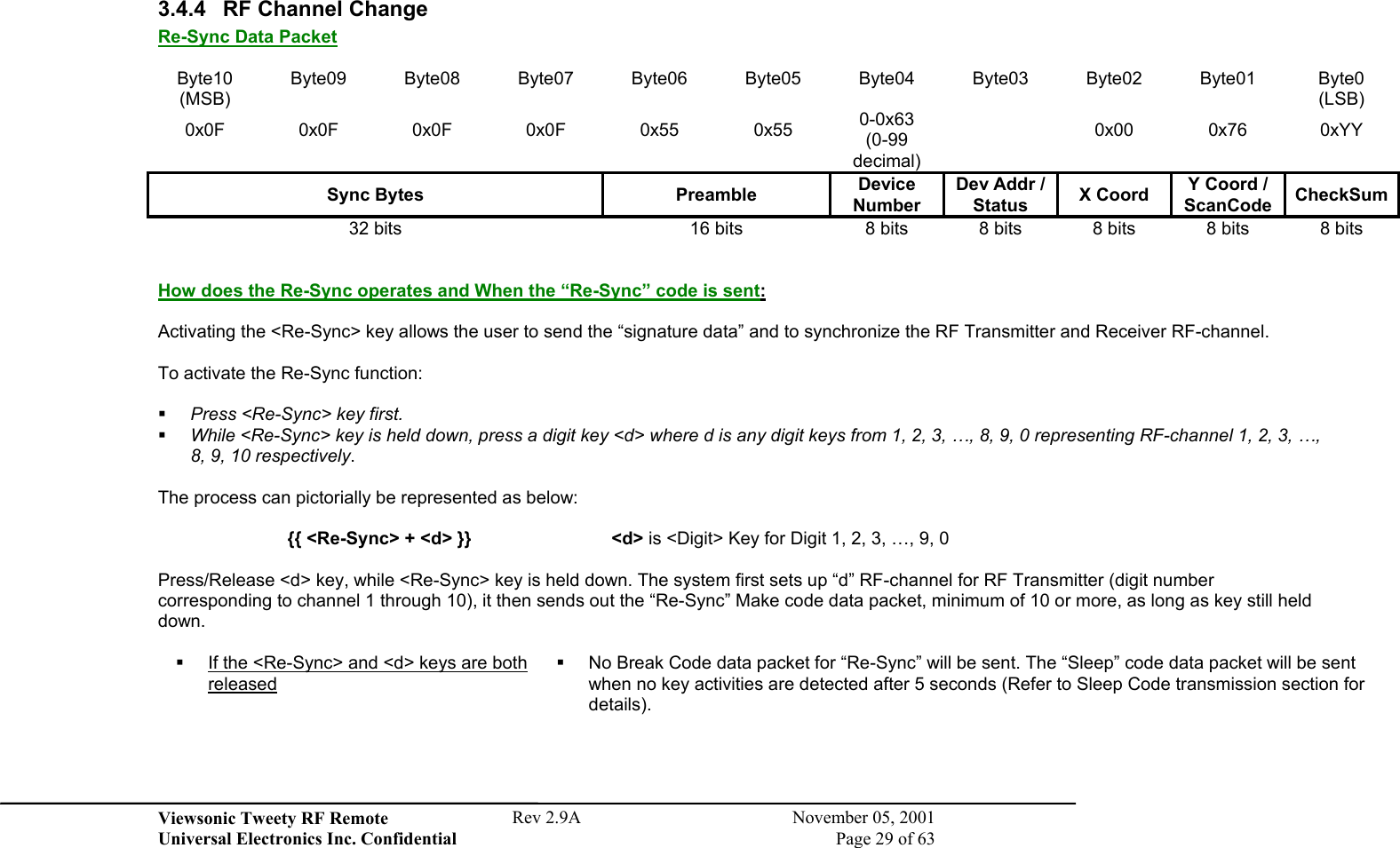
![Viewsonic Tweety RF Remote Rev 2.9A November 05, 2001 Universal Electronics Inc. Confidential Page 11 of 63 Punch Through to Last Device (by Key Group) No Record Safety No Remote Finder with Lock Option No Reset to Defaults a) Operational Reset (980) b) Manufacturing Reset (981) Section 3.3.4 No Custom Set Up Section 3.3.2 Custom Simultaneous Double Key Press - Standard Action No Simultaneous Double Key Press - Alternative Action No Sleep Feature via UEI w/Lock Option No Step and Set (991) No Stuck key Time-Out Custom Keypress = 60 sec. Pointer = 120 sec. Synthesizer No Visible LED - for user feedback No Visible LED - for mode indication No Volume Lock No No 3.1.3 Hardware Information 1. Crystal IR Carrier Operation No 2. Keyboard Layout and # of keys 34 3. LCD (Segmented, Pixel), Backlight (LED, EL) None 4. IR LEDs (1,2) (W,WW,WN) [Wide, Narrow] NA 5. Lighted Keypad (LED, EL), Color No 6. Low Voltage Detection (Software Controlled) Yes 7. Mode Indicator LEDs No 8. Modem No 9. PCB Material (Paper phenolic, FR4), Other Paper Phenolic 10. PCB Type (Single Sided, Double Sided, Silver thru holes, etc.) 11. Gold Flash Single Sided Yes-Varapoint 12. Plush Port No 13. Plush Port Opening No 14. RAM Retention NA 15. RF Operation Yes 16. RF Finder No 17. Visible LEDs for user feedback (2, 3, 5 mm) (Red, Green) No 18. 3 or 6 Volt Operation (AAA,AA) –4AAA 6V (4 AAA) 19. 6 pin E2 Interface No 20. Other (describe) N/A](https://usermanual.wiki/Universal-Electronics/4012/User-Guide-224896-Page-11.png)
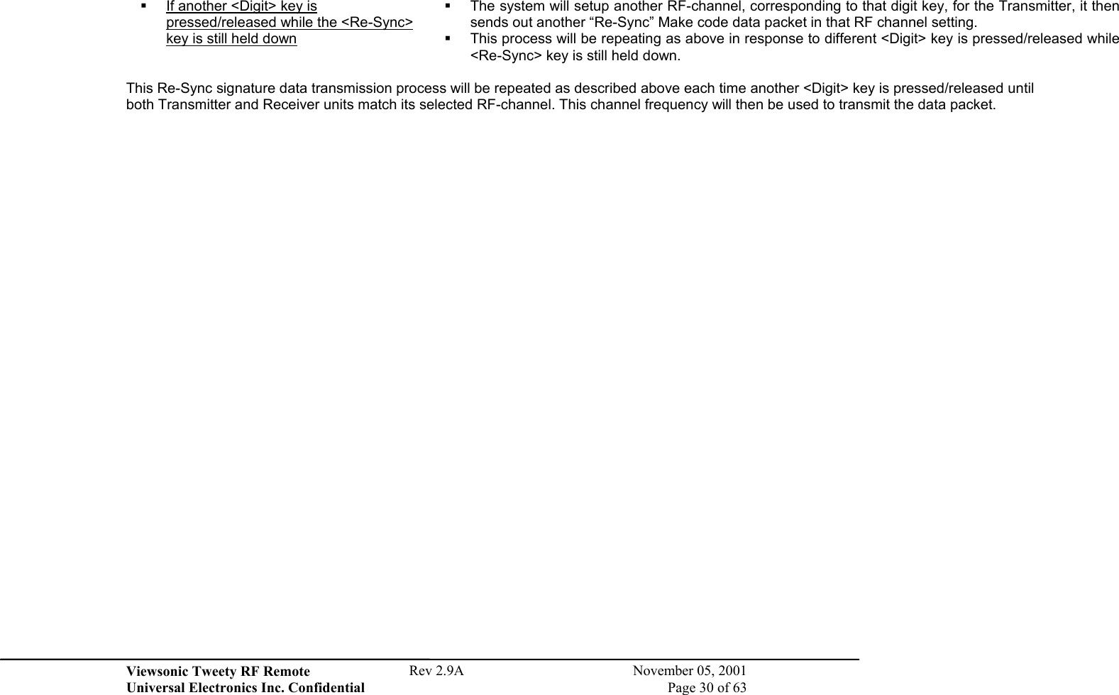
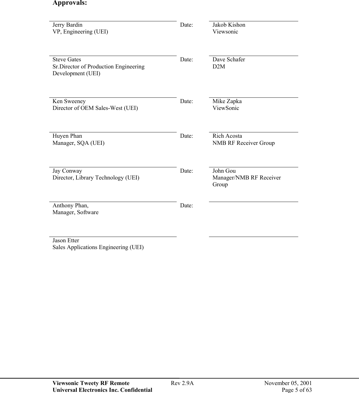
![Viewsonic Tweety RF Remote Rev 2.9A November 05, 2001 Universal Electronics Inc. Confidential Page 16 of 63 3.4 Remote UEI Key and Pointing Device Data Packet Data Packet Definition: Byte10 Byte09 Byte08 Byte07 Byte06 Byte05 Byte04 Byte03 Byte02 Byte01 Byte0 (MSB) 0x0F 0x0F 0x0F 0x0F 0x55 0x55 0-0x63 (0-99 decimal) (LSB) Sync Bytes Preamble Device Number Dev Addr / Status X Coord Y Coord / ScanCode CheckSum 32 bits 16 bits 8 bits 8 bits 8 bits 8 bits 8 bits Sync Bytes: Four data bytes of 0x0F each are used to stabilize the demodulation of the Receiver side after a period of no signal input. Preamble: Two data bytes of 0x55 each are used for decoder bit sync. Device Number: Device number from 0 to 99 (decimal) Device Address / Status: Device Address / Status Batt Pointing Device Status Device Address b7 b6 b5 b4 b3 b2 b1 b0 Described Function 0 0 0 RF Receiver 0 0 1 NMB Keyboard Keypad 0 1 0 UEI Remote Control Keypad 0 1 1 NMB Keyboard Pointing Device 1 0 0 UEI Remote Control Pointing Device Pointing Device Left Button Status (0=Up, 1=Down) Pointing Device Right Button Status (0=Up, 1=Down) X-Coordinate sign bit (0=Positive, 1=Negative) Y-Coordinate sign bit (0=Positive, 1=Negative) Battery power level Status (0=Ok, 1=Low) X-Coordinate: Keyboard Data (0), X-Data for Pointing Device. Y-Coordinate / Scan Code: Keyboard Data: Scan Code (Make/Break) [See Table 3: Scan Code Table], Y-Data for Pointing Device.](https://usermanual.wiki/Universal-Electronics/4012/User-Guide-224896-Page-16.png)