Universal Electronics 4012 ViewSonic Tweety RF Remote Control User Manual users manual
Universal Electronics Inc ViewSonic Tweety RF Remote Control users manual
users manual
Viewsonic Tweety RF Remote Rev 2.9A November 05, 2001
Universal Electronics Inc. Confidential Page 1 of 63
Pu ttin g You in Con trol of Tod ay 's Tech n ology
ViewSonic Tweety RF Remote
Product Specification
Work Order: 50-954
November 05, 2001
Rev. 2.9A
URCs: 4012B00
Author: Jason Etter

Viewsonic Tweety RF Remote Rev 2.9A November 05, 2001
Universal Electronics Inc. Confidential Page 3 of 63
Revision History
Product Revision History
Specification Software
Rev Date Ver Date
Sect. Update Description By
A 12/6/00 Initial Draft JE
B 12/20/00 1.1 Added Network Description JE
3.2.4 Added Make and Break data for MUTE
3.3.2 Revised ID Setup
3.3.3 Revised RF Channel Change
4 Added table on RF Transmission
5 Added Hardware Interface Table
6.1.2 Revised RF Channel Frequency table and added frequency control
information.
6 Revised UEI key Data Packet information
6.1.6 Added Serial Input Timing Diagram
7.4 Added Battery life information and table
C 01/12/01 1.0 Changed Part Number reflect SOP package JE
6.2 Changed Varapoint Data to reflect the Data in section 6.0
D 02/05/01 ALL
3.3.2,
3.2.4,
3.2.5
Per new NMB Specification and Bill Browns Comments
Programming Instructions per Anthony’s request
Added these sections per Anthony’s request.
JE
E 02/13/01 1.1
3.1.1
3.1.2
3.1.3
3.2.4
3.3.1
3.3.2
3.3.3
3.3.5
6
7.4
8.6
Updated IC package and part number, added comment on poly-
dome keys.
Updated IC Package Type
Referenced spec section for Mfg. Reset, SETUP, and Stuck Key
Time-out, removed visible LED for SW only to No visible LED
Changed from double sided PCB to single sided PCB and added
comment on Gold Flash required for Varapoint
Revised Key chart to match actual key labels.
Revised Stuck Key Time-out and added diagram for STUCK KEY
data packet to be sent out to HOST and added diagram for IDLE
MODE (SLEEP) data packet to be sent out to HOST
Revised ID Setup
Revised RF SETUP procedure
Added Factory Test mode for RF Channel Test
Added comment on packet data to be sent two times for all key
presses to end of this section.
Revised Battery Life Section per Bill Brown
Added Color and Printing specification
JE
Rev1.0 Kicked-off Specification JE
Rev 1.1 1.1
3.2.1/2
3.2.4
3.3
3.3.1
3.3.3
3.3.5
3.3.9
4
6
7.4
10.1
Revised IC from DIE package to QFP
Changed Target Device from TV to Viewsonic
Updated Key Table
Updated Definitions in regards to LED blinking methodology
Updated Stuck Key, sleep and Keep alive information and appendix
Updated RF Channel Change section
Updated Factory Test
Updated Low Battery section for the 6volt design
Changed data rate from max. 19.2 bps to fixed 9600 bps
Updated Data Packet and Pointing device information
Added statement on the each key press is calculates @ 1 second
Changed Low non operating range from –20 C to -10C
JE

Viewsonic Tweety RF Remote Rev 2.9A November 05, 2001
Universal Electronics Inc. Confidential Page 4 of 63
Rev 2.0 3.1.1
3.3
3.1.3
3.1.4
3.1.5
3.4
1.1, 4,
6.1.1
4
4.1
Changed IC package to QFP (from DIE)
Changed MUTE to RESYN in “Conventions and Notations”
Changed PCB material from FR4 to Paper Phenolic
Item 14- Added URC number
Item 3- No FCC testing by UEI
Revised “Remote UEI Key and Pointing Device Data Packet”
Changed RF Operating Band range to 2446.7 – 2464.3MHz
Table 2, Rqmt No. 4.10 – Changed to “Simplex”
Added Manchester Data Coding table
Lee
Rev 2.1 5.1.1
5.1.2
5.1.3
Revised RF Channel and Operating Bands
Revised RF Channels and Frequencies
Added Pulse Width Timing section
JE
2.2 2.1.1
3.1.5
3.1.6
10.2
Added comment that NMB receiver Spec 0.9 takes precedence
Modified item 3 to state FCC certification will be done by Optoma
with UEI for support only.
Item 1 (Batteries Included) has been changed from No to Yes-Bulk
Item 2 (Batter Cover) Rating Label required has been changed from
No to yes installed in specified area.
Item 10 Device Label in addition to packaging changed from Yes
to Installed on Unit
Changed FCC requirement to read as follows “Optoma will certify
the complete unit with remote and keyboard.
With documentation and possible engineering support to Optoma
from UEI.
JE
2.3 3.4 &
3.4.7.1
3.4.6.1
5.1.2
Added provision to allow for using the varapoint mouse and the left
and Right select keys simultaneously
Add notes on power state for entering Factory Test modes and E2
Revised RF Channels and Frequencies
JE
2.4 5.1.2 Revised RF Channel Data to match the transmission table JE
2.5 7.6
11
3.2.4,
3.4.6.2
Updated Color Specification Chart
Imported revised rendering dated 8/15/01 Style A rev 3.0
Updated Key charts for Smart and Enter Key
JE
2.6 3.4
3.4.3
3.4.5
4.12
Added Definition for Mouse Right and Left while used in conjunction
with the mouse
Updated Device Number Setup definition
Updated E2 Initializtion Definition
Changed power source from 2.2VDC to 2.2VDC
JE
2.7 3.2.4,
3.4.6.2,
7.6
11
Updated key-tables to reflect silk-screening changes
Updated Rendering imported with silk-screening changes
JE
2.8 11 Updated Rendering with new Vara-touch pointer JE
2.9 3.2.4,
3.4.6.2
3.4
Added Break Data ‘F6’ for the Sync Key
Added Break Data ‘F6’ for the Sync Key
Revised Comment in Re-Sync Section in regards to no Break-Code
being sent after the Re-Sync key was released.
JE
2.91 1.1
4.9
Corrected Frequency
Output power is –18dbm
RM

Viewsonic Tweety RF Remote Rev 2.9A November 05, 2001
Universal Electronics Inc. Confidential Page 5 of 63
Approvals:
Jerry Bardin
VP, Engineering (UEI)
Date: Jakob Kishon
Viewsonic
Steve Gates
Sr.Director of Production Engineering
Development (UEI)
Date: Dave Schafer
D2M
Ken Sweeney
Director of OEM Sales-West (UEI)
Date: Mike Zapka
ViewSonic
Huyen Phan
Manager, SQA (UEI)
Date: Rich Acosta
NMB RF Receiver Group
Jay Conway
Director, Library Technology (UEI)
Date: John Gou
Manager/NMB RF Receiver
Group
Anthony Phan,
Manager, Software
Date:
Jason Etter
Sales Applications Engineering (UEI)

Viewsonic Tweety RF Remote Rev 2.9A November 05, 2001
Universal Electronics Inc. Confidential Page 6 of 63
Table of Contents
Product Revision History ...........................................................................................................................................................................3
1 Purpose and Scope .....................................................................................................................................................................8
1.1 Description.................................................................................................................................. 8
1.2 Project Type ................................................................................................................................8
2 Applicable Documents ..............................................................................................................................................................8
2.1 Project Documentation ........................................................................................................... 8
2.1.1 Customer Specification ............................................................................................... 9
2.1.2 Other Product Documentation ................................................................................. 9
2.2 UEI Standard Documentation .............................................................................................. 9
2.2.1 UEI Standard Glossary.................................................................................................. 9
2.2.2 UEI Standard Hardware General Information .................................................... 9
2.2.3 UEI Standard Operational Features Descriptions ............................................ 9
2.2.4 UEI Standard Testing Procedures............................................................................ 9
3 Functional Requirements ....................................................................................................................................................... 9
3.1 Product Summary..................................................................................................................... 9
3.1.1 General Information ...................................................................................................... 9
3.1.2 Software Information.................................................................................................... 9
3.1.3 Hardware Information .................................................................................................11
3.1.4 Mechanical Information .............................................................................................12
3.1.5 Quality/ Testing Information...................................................................................12
3.1.6 Miscellaneous Information ........................................................................................13
3.2 Product Library.........................................................................................................................13
3.2.1 Target Device Mode Mapping ...................................................................................13
3.2.2 Defaults..............................................................................................................................13
3.2.3 Library Upgrade Support ............................................................................................13
3.2.4 Key Table .............................................................................................................................14
3.3 Operational Features......................................................................................................................15
3.4 Remote UEI Key and Pointing Device Data Packet......................................................................16
3.4.1 Definitions ............................................................................................................................20
3.4.2 Time Event / Data Packet Transmission Diagram............................................................23
Some notations used in the Time Event / Data Packet Diagram .....................................................27
Notation 27
Function Description ...........................................................................................................................27
Make ...........................................................................................................................................................................................................27
3.4.3 Device Number Setup..........................................................................................................28
3.4.4 RF Channel Change ............................................................................................................29
3.4.5 E2 Initialization....................................................................................................................31
3.4.6 Factory Test Mode(s)...........................................................................................................32
3.4.7 Key Test (Also used in Factory Test for Key): ..................................................................33
3.4.8 Low Battery Indicator.........................................................................................................38
4 RF Transmission General Specification .......................................................................................................................................39
4.1 Data Coding...................................................................................................................................40
5 Hardware Interface.........................................................................................................................................................................41
5.1 Transmitter Outline /Interface .......................................................................................................41
5.1 Product Performance Requirements ..............................................................................................43
5.1.1 RF CHANNEL and OPERATING BANDS......................................................................43
5.1.2 RF Channels and Frequencies ............................................................................................43
5.1.3 RF Channel Operation Range ............................................................................................44
5.1.4 RF Modulation Scheme and Modulation Level ................................................................44
5.1.5 Maximum Bit Rate ..............................................................................................................44
5.1.6 RF Power Management.......................................................................................................44
• T2 = Frequency Stable Time. Typically, it should be T2 > 20ms ............................................44
5.1.7 Transmitter Data Input Level ............................................................................................44
The transmitter data input level should be fixed as the supply voltage drops when using battery.
It is required that the Input level will be Vp-p = 100mv (+/- 10%).................................................44

Viewsonic Tweety RF Remote Rev 2.9A November 05, 2001
Universal Electronics Inc. Confidential Page 7 of 63
5.1.8 Communication Link...........................................................................................................44
6 Electrical Requirements .................................................................................................................................................................46
6.1 Power.............................................................................................................................................46
6.2 Visible LEDs .................................................................................................................................46
NA .............................................................................................................................................................46
6.3 Transmission IC.............................................................................................................................46
6.4 Battery Life....................................................................................................................................46
6.5 Range.............................................................................................................................................46
7 Mechanical Requirements..............................................................................................................................................................47
7.1.1 HRC Assembly.....................................................................................................................47
7.1.2 Assembly LED’s...................................................................................................................47
7.2 Enclosure.......................................................................................................................................47
7.2.1 Enclosure and Battery Cover Shape ..................................................................................47
7.2.2 Material ................................................................................................................................47
7.2.3 Texture..................................................................................................................................48
7.2.4 Color .....................................................................................................................................48
7.3 Keypad with Polydome .................................................................................................................48
7.3.1 Material ................................................................................................................................48
7.3.2 Tactile Feel ...........................................................................................................................48
7.3.3 Force Vs. Travel...................................................................................................................49
7.3.4 Life ........................................................................................................................................50
7.3.5 Keypad Pull-out Force ........................................................................................................50
7.3.6 Key stick and key stuck.......................................................................................................50
7.4 PCB Material .................................................................................................................................50
7.5 Battery Compartment ....................................................................................................................50
7.6 Printing ..........................................................................................................................................50
7.7 Labeling.........................................................................................................................................52
7.7.1 Date Code .............................................................................................................................52
7.7.2 Part Number Label..............................................................................................................52
7.7.3 Country of Origin ................................................................................................................52
8 QUALITY ........................................................................................................................................................................................53
8.1 Appearance ....................................................................................................................................53
8.2 Cosmetic........................................................................................................................................53
8.2.1 Evaluation Criteria..............................................................................................................53
8.2.2 Definition of Flaw and Defect .............................................................................................54
8.2.3 Definition of Classes ............................................................................................................54
8.2.4 Cosmetic Evaluation............................................................................................................55
8.3 Durability Testing..........................................................................................................................56
8.3.1 Structure and Strength........................................................................................................56
8.3.2 Printing.................................................................................................................................56
8.3.3 Battery Contact....................................................................................................................57
8.3.4 Painting wear test (if necessary) .........................................................................................57
8.3.5 Rubber coating wear test (if necessary).............................................................................57
8.3.6 Epoxy key test ......................................................................................................................57
9 ENVIRONMENTAL & SHOCK REQUIREMENTS ................................................................................................................59
9.1 Temperature...................................................................................................................................59
9.2 Humidity Test................................................................................................................................59
9.3 Low Temperature Test...................................................................................................................59
9.4 High Temperature Test..................................................................................................................59
9.5 Thermal Shock...............................................................................................................................60
9.6 Drop Test.......................................................................................................................................60
9.7 Solvent Resistance.........................................................................................................................61
9.8 Liquid Spill....................................................................................................................................61
10 Standard Compliances...............................................................................................................................................................62
10.1 ESD Protection ..............................................................................................................................62
10.2 FCC ...............................................................................................................................................62
11 Rendering....................................................................................................................................................................................63

Viewsonic Tweety RF Remote Rev 2.9A November 05, 2001
Universal Electronics Inc. Confidential Page 8 of 63
Purpose and Scope
1.1 Description
The Viewsonic-Tweety remote will be a dedicated 2.4 gHz RF remote with 10 channel capability.
This will be a 6V product and will use 4 AAA batteries. It will use a Samsung 16K
(S3P/C80F9XFE-QZR5) (QFP) Micro-controller.
Network Description:
The RF modules support up to 10 channels in the ISM band of 2446.7MHz to 2464.3MHz,
providing a form of frequency division multiple access (FDMA). This enables the simple
implementation of systems requiring multiple devices to be operating continuously and
concurrently.
Note: This document contains all functional specifications and testing/quality requirements
that UEI will perform. By signing off on this document, the customer agrees that these
product/project parameters are final. Any further revisions will be accompanied by
Engineering Change Request and appropriate authorizations.
Features
• Samsung 16K(QFP)
• E2 (128 byte) –To save RF Channel Data and Device ID
• 34 keys
• 6V product (4 AAA)
• Varapoint
• W-Link 2.4 gHz RF transmitter
• Slide Door
• Poly Dome Keys
1.2 Project Type
OEM-West
2 Applicable Documents
Appendix A: NMB/UEI Remote Devices and Receiver Module Rev. 0.1
Appendix B: NMB RF-Receiver (UART) and HOST (Image Processor)
2.1 Project Documentation
The following documents of exact issue and date form part of this specification:
Viewsonic Tweety RF Remote Rev 2.9A November 05, 2001
Universal Electronics Inc. Confidential Page 9 of 63
2.1.1 Customer Specification
NMB RF-Receiver and Host Image Processor rev 0.9
(This spec takes precedence a changes to the receiver software must also be made to
the remote and keyboard)
2.1.2 Other Product Documentation
N/A
2.2 UEI Standard Documentation
UEI SPEC 0020, UEI SPEC HE003, UEI SPEC 0002
2.2.1 UEI Standard Glossary
N/A
2.2.2 UEI Standard Hardware General Information
Refer to Section 3.1.3
2.2.3 UEI Standard Operational Features Descriptions
2.2.4 UEI Standard Testing Procedures
Refer to Section 6.0, Section 7.0 and Section 9.0.
3 Functional Requirements
3.1 Product Summary
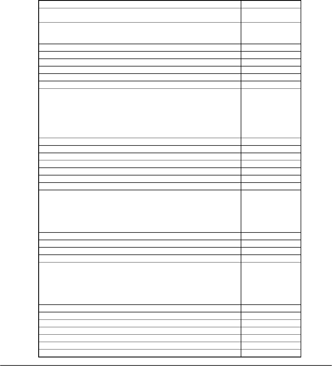
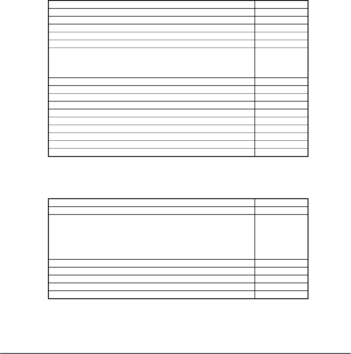
3.1.1 General Information
Functional Keychart Included Yes
IC Type and size and package type Samsung (16K)
(QFP)
Keypad Parameters Specified Yes
Mode Indicator LEDs No
Multiple Devices (Jumpers) No
OTPs Used for initial Production Yes
Product Development Type:
OFA, OEM, Private Label, Cable, Chip Only
OEM-West
Request Load Included NA
Upgradeable Product (E2) NA
3.1.2 Software Information
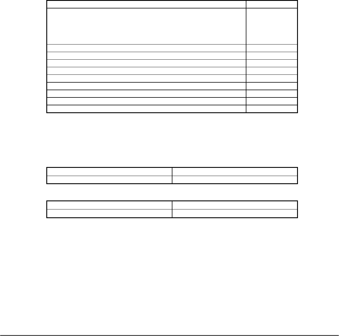
Channel Scan No
Channel +/- Simulation w/Lock Option No
Viewsonic Tweety RF Remote Rev 2.9A November 05, 2001
Universal Electronics Inc. Confidential Page 10 of 63
Channel Lock No
Device Mode Keys
DEDICATED
Dual Functional via Shift Key
a) One Time Use
b) Shift Lock w/Time-Out
No
No
E2 Auto-Sizing No
E2 Device Mode Lock No
E2 Upgradeable via Modem (997) No
E2 Upgradeable via 6 pin interface No
Factory Test Mode Yes
Favorite Channel Scan (996) No
Functional Keys – Additional
a) brightness Control
b) Color Control
c) Menu
d) Shifted Functions With/without time-outs
e) Teletext – Simple
f) Teletext – Fastext
No
No
No
No
No
No
Functional Keys – Standard Yes
Hidden Keys No
High Frequency Capable No
ID Code Verification No
ID Default Selection No
ID Lock/Unlock for Specific Mode No
ID – Number of Digits NA
ID Offset
a) Constant number offset to all Ids
b) Offset by Hardware setting (Jumper,....)
c) Custom renumbering to some or all Ids
None
None
None
Illuminated Key Pad No
Keymover (994) – Full with Synthesizer No
Liquid Crystal Display (LCD) No
Low Voltage Detection – Software Yes
Macros
a) Hard Coded
b) Premium Channel
c) User Defined
1) Single
2) Multi-level Rotating
No
No
No
No
Mode Reassignment (992) No
Modem No
Network Downloading No
Power On Mode Key No
Power Toggle No
Power Up w/Default Device Mode and Codes No
Power Up w/ No Defaults No
Viewsonic Tweety RF Remote Rev 2.9A November 05, 2001
Universal Electronics Inc. Confidential Page 11 of 63
Punch Through to Last Device (by Key Group) No
Record Safety No
Remote Finder with Lock Option No
Reset to Defaults
a) Operational Reset (980)
b) Manufacturing Reset (981) Section 3.3.4
No
Custom
Set Up Section 3.3.2 Custom
Simultaneous Double Key Press - Standard Action No
Simultaneous Double Key Press - Alternative Action No
Sleep Feature via UEI w/Lock Option No
Step and Set (991) No
Stuck key Time-Out Custom
Keypress = 60 sec.
Pointer = 120 sec.
Synthesizer No
Visible LED - for user feedback No
Visible LED - for mode indication No
Volume Lock No
No
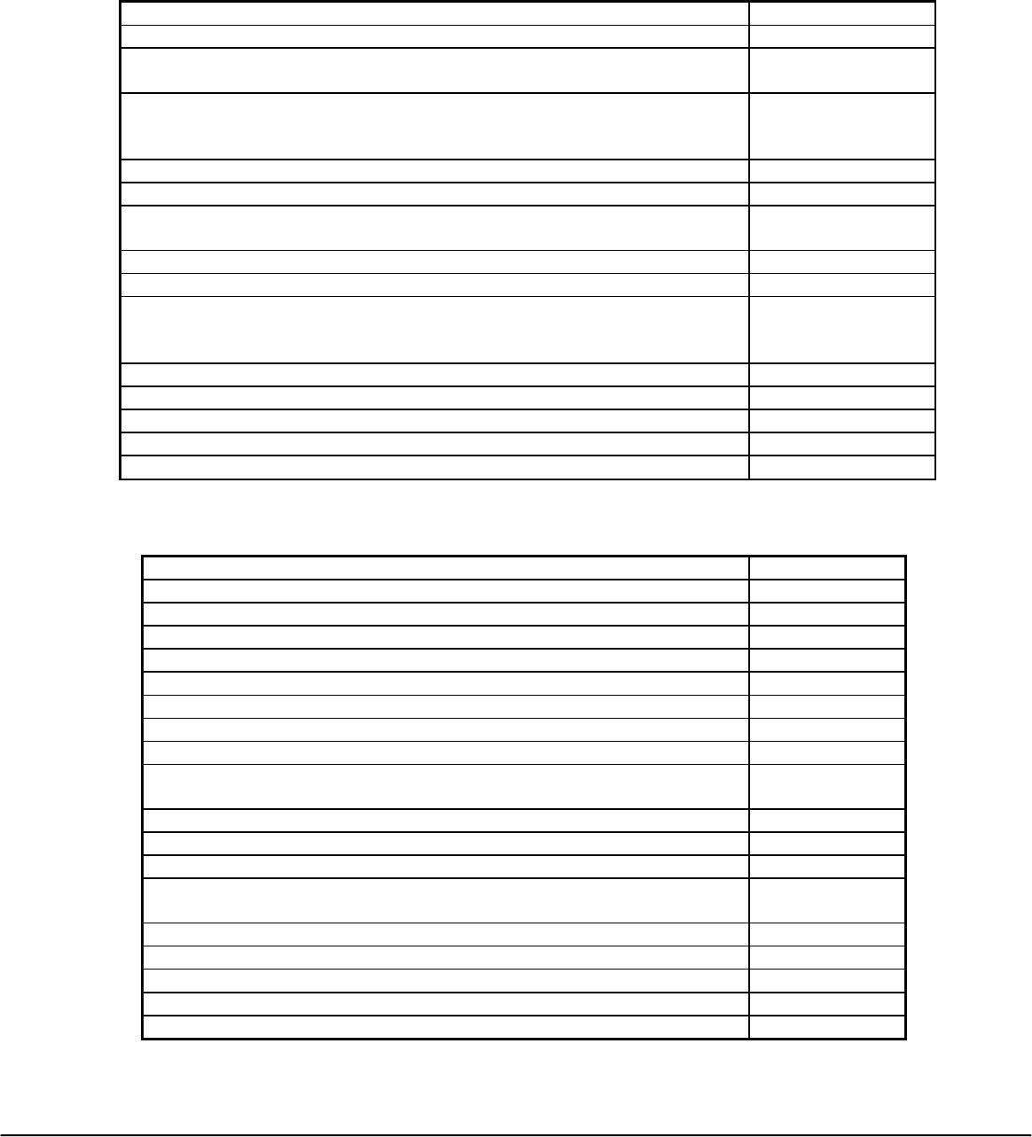
3.1.3 Hardware Information
1. Crystal IR Carrier Operation No
2. Keyboard Layout and # of keys 34
3. LCD (Segmented, Pixel), Backlight (LED, EL) None
4. IR LEDs (1,2) (W,WW,WN) [Wide, Narrow] NA
5. Lighted Keypad (LED, EL), Color No
6. Low Voltage Detection (Software Controlled) Yes
7. Mode Indicator LEDs No
8. Modem No
9. PCB Material (Paper phenolic, FR4), Other Paper Phenolic
10. PCB Type (Single Sided, Double Sided, Silver thru holes, etc.)
11. Gold Flash
Single Sided
Yes-Varapoint
12. Plush Port No
13. Plush Port Opening No
14. RAM Retention NA
15. RF Operation Yes
16. RF Finder No
17. Visible LEDs for user feedback (2, 3, 5 mm) (Red, Green) No
18. 3 or 6 Volt Operation (AAA,AA) –4AAA 6V (4 AAA)
19. 6 pin E2 Interface No
20. Other (describe) N/A
Viewsonic Tweety RF Remote Rev 2.9A November 05, 2001
Universal Electronics Inc. Confidential Page 12 of 63
3.1.4 Mechanical Information
1. Battery Compartment Yes
2. Colors & Labels Section 8.2.4
3. Force versus Travel (Keypad with Polydome) Section 8.3.3
4. IR Lens No
5. Key Clearance Section
6. Keypad Definition Yes
7. List of Consigned Parts Microcontroller
EEprom
RF Transmitter
Varapoint
8. Material Section
9. Overlay No
10. Packaging Requirements in BOM Bulk
11. Plastic Case design or rendering included Yes
12. Prototype/Model Yes
13. Sliding Door Yes
14. Unique Parts No
15. URC with B00# 4012B00
16. Weight TBD
17. Other (describe) Viewsonic Jewel
3.1.5 Quality/ Testing Information
1. Environmental Testing Yes
2. ESD Protection Yes
3. FCC or UL Certification Requirements No- Optoma to
apply for
certification UEI
will supply
support.
4. Production Line Testing Procedures Yes
5. Quality Assurance Provisions UEI Standard
6. Reliability Testing Yes
7. SIO Test Verification No
8. Other (describe) N/A
Viewsonic Tweety RF Remote Rev 2.9A November 05, 2001
Universal Electronics Inc. Confidential Page 13 of 63
3.1.6 Miscellaneous Information
1. Batteries (Included) Yes-Bulk
2. Battery Cover
a) Rating label silk screened on outside of battery door
Yes, label to be
installed in
specified area
3. Customer Service Support Required No
4. Date Code Label Yes
5. Labeling Yes
6. Packaging Yes-Bulk
7. Units per Box – shipping 100
8. Users Manual Development (Type: staples/folded map) NA
9. User Manual Type Responsibility Customer
10. Device Label- inside addition to package Installed on unit
11. Country of Origin Location: Molded, Label, Silkscreened On Rating Label
3.2 Product Library
This will be a dedicated remote.
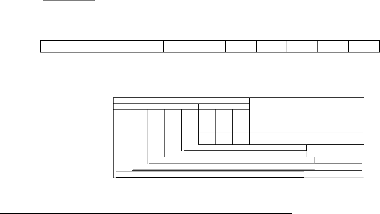
3.2.1 Target Device Mode Mapping
Mode Load/ Device Assignment
Viewsonic Dedicated
3.2.2 Defaults
Mode/Feature Default State
Viewsonic RF Channel 1
3.2.3 Library Upgrade Support
N/A

Viewsonic Tweety RF Remote Rev 2.9A November 05, 2001
Universal Electronics Inc. Confidential Page 14 of 63
3.2.4 Key Table
Key # Key Label Make Code Break Code
1 POWER 75 F5
2 VL+ 74 F4
3 VL- 73 F3
4 MUTE 6B EB
5 CH+ 6F EF
6 CH- 70 F0
7 PREVIOUS 6D ED
8 MENU/EXIT 6E EE
9 PIP 6C EC
10 ENTER * *
11 SMART * *
12 REVERSE 57 D7
13 PLAY 58 D8
14 FFD 59 D9
15 RECORD 5A DA
16 STOP 5B DB
17 PAUSE 5C DC
18 INSTANT REPLAY 5D DD
19 JUMP COMM 5E DE
20 JUMP PRESENT 5F DF
21 EPG 60 E0
22 +100 61 E1
23 MULTIVIEW 62 E2
24 1 13 93
25 2 14 94
26 3 15 95
27 4 16 96
28 5 17 97
29 6 18 98
30 7 19 99
31 8 1A 9A
32 9 1B 9B
33 0 1C 9C
34 RE-SYNC 76 F6
* SET and Reset in Pointing Device Data Packet

Viewsonic Tweety RF Remote Rev 2.9A November 05, 2001
Universal Electronics Inc. Confidential Page 15 of 63
3.3 Operational Features
Conventions and Notations
The operation of the remote control and the programming sequence use the following
shorthand notations.
The relational operator <<>> around a key is an instruction to press and hold the key for 3
seconds.
For example:
<<RESYNC + CH+ >>
Press RESYNC and hold for 3 seconds
The relational operator <> around a key is an instruction to press the key and then release.
For example:
<RESYNC>
Viewsonic Tweety RF Remote Rev 2.9A November 05, 2001
Universal Electronics Inc. Confidential Page 16 of 63
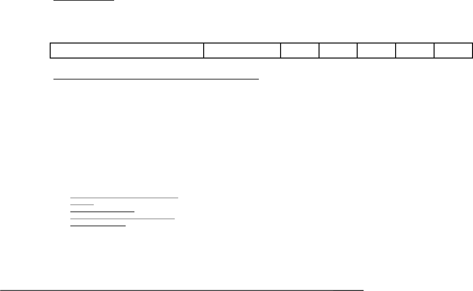
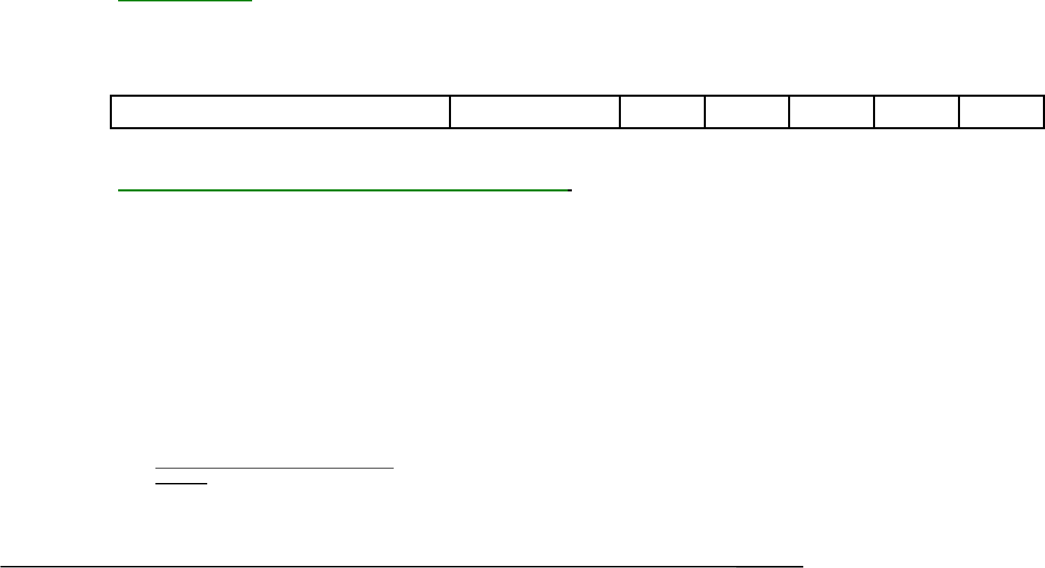
3.4 Remote UEI Key and Pointing Device Data Packet
Data Packet Definition:
Byte10 Byte09 Byte08 Byte07 Byte06 Byte05 Byte04 Byte03 Byte02 Byte01 Byte0
(MSB)
0x0F
0x0F
0x0F
0x0F
0x55
0x55
0-0x63
(0-99
decimal)
(LSB)
Sync Bytes
Preamble Device
Number
Dev Addr /
Status
X Coord Y Coord /
ScanCode
CheckSum
32 bits 16 bits 8 bits 8 bits 8 bits 8 bits 8 bits
Sync Bytes: Four data bytes of 0x0F each are used to stabilize the demodulation of the Receiver side after a period of no
signal input.
Preamble: Two data bytes of 0x55 each are used for decoder bit sync.
Device Number: Device number from 0 to 99 (decimal)
Device Address / Status:
Device Address / Status
Batt Pointing Device Status Device Address
b7 b6 b5 b4 b3 b2 b1 b0
Described Function
0 0 0 RF Receiver
0 0 1 NMB Keyboard Keypad
0 1 0 UEI Remote Control Keypad
0 1 1 NMB Keyboard Pointing Device
1 0 0 UEI Remote Control Pointing Device
Pointing Device Left Button Status (0=Up, 1=Down)
Pointing Device Right Button Status (0=Up, 1=Down)
X-Coordinate sign bit (0=Positive, 1=Negative)
Y-Coordinate sign bit (0=Positive, 1=Negative)
Battery power level Status (0=Ok, 1=Low)
X-Coordinate: Keyboard Data (0), X-Data for Pointing Device.
Y-Coordinate / Scan Code: Keyboard Data: Scan Code (Make/Break) [See Table 3: Scan Code Table], Y-Data for Pointing Device.

Viewsonic Tweety RF Remote Rev 2.9A November 05, 2001
Universal Electronics Inc. Confidential Page 17 of 63
CheckSum: The sum of Device Number + Device Address / Status + X-Coordinate + Y-Coordinate/Scan Code.
(Add all the indicated bytes without carry’s).
LEFT/RIGHT MOUSE key Operation
1. When the
<Left> key is pressed, its corresponding pointing device left key status (Bit 3) in the Device Address / Status Byte will be set.
This bit will be set as long as the <Left> key is held down, and it will be reset (or cleared) when the <Left> key is released.
1.1. While the <Left> key is held down:
a) If the Pointing Device is not active, the transmitted data packet will have Left key status bit in the Device Address / Status Byte
set and the X-Coordinate Byte and Y-Coordinate / Scan Code Byte contained all zeros.
b) If the Pointing Device is active, the transmitted data packet will have Left key status bit in the Device Address / Status Byte set
and the X-Coordinate Byte and Y-Coordinate / Scan Code Byte contained the X and Y positional values of the Pointer movement.
1.2. While the <Left> key is pressed and held down, if another key (other than <Right> key) is now pressed, the pointing device Left key
status bit in the Device Address / Status Byte will be reset.
a) If the Pointing Device is not active, no data packet will be transmitted. Both keys must be released for the remote to return to its
normal operation
b) If the Pointing Device is active prior to the key presses as described in 1.2 above, the transmitted data packet will have Left key
status bit in the Device Address / Status Byte reset and the X-Coordinate Byte and Y-Coordinate / Scan Code Byte contained the
X and Y positional values of the Pointer movement.
2. When the <Right> key is pressed, its corresponding pointing device right key status (Bit 4) in the Device Address / Status Byte will be set.
This bit will be set as long as the <Right> key is held down, and it will be reset (or cleared) when the <Right> key is released.
2.1. While the <Right> key is held down:
a) If the Pointing Device is not active, the transmitted data packet will have Right key status bit in the Device Address / Status Byte
set and the X-Coordinate Byte and Y-Coordinate / Scan Code Byte contained all zeros.
b) If the Pointing Device is active, the transmitted data packet will have Right key status bit in the Device Address / Status Byte set
and the X-Coordinate Byte and Y-Coordinate / Scan Code Byte contained the X and Y positional values of the Pointer movement.
2.2. While the <Right> key is pressed and held down, if another key (other than <Left> key) is now pressed, the pointing device Right key
status bit in the Device Address / Status Byte will be reset.

Viewsonic Tweety RF Remote Rev 2.9A November 05, 2001
Universal Electronics Inc. Confidential Page 18 of 63
a) If the Pointing Device is not active, no data packet will be transmitted. Both keys must be released for the remote to return to its
normal operation
b) If the Pointing Device is active prior to the key presses as described in 2.2 above, the transmitted data packet will have Right key
status bit in the Device Address / Status Byte reset and the X-Coordinate Byte and Y-Coordinate / Scan Code Byte contained the
X and Y positional values of the Pointer movement.
3. When
<Left> and <Right>) keys are both being held down (with one key is pressed before the other), the corresponding pointing device
left key status (Bit 3) and right key status (Bit 4) in the Device Address / Status Byte will both be set. These bits will be set as long as
the <Left> and <Right> keys are held down. If any one of these two keys is released first, its corresponding status bit will be reset while
the corresponding status bit of remaining key remains set. Both bits will be reset (or cleared) when both keys are released. During this
time, if the Pointing Device is not active, the X-Coordinate Byte and Y-Coordinate / Scan Code Byte will be all zeros in the transmitted data
packet.
Note: It is up to the Host application software to make use of the case where both left and right key status bits in the Device Address /
Status Byte are set. This condition would indicate that both <Left> and <Right> keys are currently being pressed and held down.
4. When the Pointing Device is active and one (or both) of <Left> (or <Right>) key is pressed, the X-Coordinate Byte and Y-Coordinate /
Scan Code Byte will be updated with the X and Y value of their corresponding positional movements. The transmitted data packet will
have the corresponding Left (or Right) key status bit in the Device Address / Status Byte set or reset accordingly.
Note:
If both keys <Left> and <Right> are pressed at the same time, this would be considered as invalid (simultaneously key press). There will be
no data packet sent out in this case.
Viewsonic Tweety RF Remote Rev 2.9A November 05, 2001
Universal Electronics Inc. Confidential Page 19 of 63
Re-Sync Data Packet
Byte10 Byte09 Byte08 Byte07 Byte06 Byte05 Byte04 Byte03 Byte02 Byte01 Byte0
(MSB)
0x0F
0x0F
0x0F
0x0F
0x55
0x55
0-0x63
(0-99
decimal)
0x00
0x76
(LSB)
0xYY
Sync Bytes
Preamble Device
Number
Dev Addr /
Status
X Coord Y Coord /
ScanCode
CheckSum
32 bits 16 bits 8 bits 8 bits 8 bits 8 bits 8 bits
How does the Re-Sync operates and When the “Re-Sync” code is sent:
Activating the <Re-Sync> key allows the user to send the “signature data” and to synchronize the RF Transmitter and Receiver RF-channel.
To activate the Re-Sync function:
Press <Re-Sync> key first.
While <Re-Sync> key is held down, press a digit key <d> where d is any digit keys from 1, 2, 3, …, 8, 9, 0 representing RF-channel 1,
2, 3, …, 8, 9, 10 respectively.
The process can pictorially be represented as below:
{{ <Re-Sync> + <d> }} <d> is <Digit> Key for Digit 1, 2, 3, …, 9, 0
Press/Release <d> key, while <Re-Sync> key is held down. The system first sets up “d” RF-channel for RF Transmitter (digit number
corresponding to channel 1 through 10), it then sends out the “Re-Sync” Make code data packet, minimum of 10 or more, as long as key still held
down.
If the <Re-Sync> and <d> keys are both
released
The “Sleep” code data packet will be sent when no key activities are detected after 5 seconds (Refer to
Sleep Code transmission section for details).
If another <Digit> key is
pressed/released while the <Re-Sync>
key is still held down
The system will setup another RF-channel, corresponding to that digit key, for the Transmitter, it then
sends out another “Re-Sync” Make code data packet in that RF channel setting.
This process will be repeating as above in response to different <Digit> key is pressed/released while
<Re-Sync> key is still held down.
This Re-Sync signature data transmission process will be repeated as described above each time another <Digit> key is pressed/released until
both Transmitter and Receiver units match its selected RF-channel. This channel frequency will then be used to transmit the data packet.
Viewsonic Tweety RF Remote Rev 2.9A November 05, 2001
Universal Electronics Inc. Confidential Page 20 of 63
3.4.1 Definitions
Stuck Key Time-out
After any key is pressed continuously for 60 seconds, the remote will stop sending data packets and turn off RF transmission to conserve battery life.
Transmission can begin again, after all keys are released and key is pressed.
Stuck-Key Data Packet
Byte10 Byte09 Byte08 Byte07 Byte06 Byte05 Byte04 Byte03 Byte02 Byte01 Byte0
(MSB)
0x0F
0x0F
0x0F
0x0F
0x55
0x55
0-0x63
(0-99
decimal)
0x00
0xFC
(LSB)
0xYY
Sync Bytes
Preamble Device
Number
Dev Addr /
Status
X Coord Y Coord /
ScanCode
CheckSum
32 bits 16 bits 8 bits 8 bits 8 bits 8 bits 8 bits
How and When the Stuck-Key code is sent:
The Stuck-Key Code Data Packet will be sent:
After two data packets of the Make Code of the detected key press, <K1> say, have been sent out. If this (same) key, <K1>, is still being held down for more
than 60 seconds, then two data packets of Stuck-Key code will be sent with 10 ms delay time interval between data packets. A Make Code data packet of the
same key sent every 70 ms time interval during this 60 seconds stuck key condition.
For the pointing device, after sending out the X-Coord and Y-Coord continuously up to 2 minutes which is the time to be considered as stuck key timeout for
pointing device. Two data packets of Stuck Code will be sent.
Two data packets of Sleep Code will be sent following the Stuck Code data packet. The RF Transmitter will then be turned OFF.
Sleep Mode
This is the idle state of the micro-controller when it draws the least amount of current. Upon entering the idle mode, the remote will transmit a unique byte
(FD) to notify the receiver that it is entering into the sleep mode.

Viewsonic Tweety RF Remote Rev 2.9A November 05, 2001
Universal Electronics Inc. Confidential Page 21 of 63
Sleep Data Packet
Byte10 Byte09 Byte08 Byte07 Byte06 Byte05 Byte04 Byte03 Byte02 Byte01 Byte0
(MSB)
0x0F
0x0F
0x0F
0x0F
0x55
0x55
0-0x63
(0-99
decimal)
0x00
0xFD
(LSB)
0xYY
Sync Bytes
Preamble Device
Number
Dev Addr /
Status
X Coord Y Coord /
ScanCode
CheckSum
32 bits 16 bits 8 bits 8 bits 8 bits 8 bits 8 bits
How and When the Sleep code is sent:
The Sleep Code Data Packet will be sent:
After depressed key, <K1> say, is released and two Data-Packets of K1 Break Code sent, the RF Transmitter will be turned OFF. If no other key press activities are
detected after 5 seconds, the RF Transmitter will then be turned ON to send two data packets of Sleep code , the RF Transmitter will again be turned OFF and the
remote software goes into its actual Sleep mode.
3.4.1.1 Repeated Make code Data Packet
Byte10 Byte09 Byte08 Byte07 Byte06 Byte05 Byte04 Byte03 Byte02 Byte01 Byte0
(MSB)
0x0F
0x0F
0x0F
0x0F
0x55
0x55
0-0x63
(0-99
decimal)
0x00
(LSB)
0xYY
Sync Bytes
Preamble Device
Number
Dev Addr /
Status
X Coord Y Coord /
ScanCode
CheckSum
32 bits 16 bits 8 bits 8 bits 8 bits 8 bits 8 bits
How and When the repeated Make Code is sent:
The repeated Make Code Data Packet will be sent:
After a depressed key, <K1> say, is detected, two data packets of its Make code will be sent with 10 ms delay between data packets. The
Make code packet of the same key will be sent out for every 70 ms time interval as long as this <K1> is still being held down and the overall
time since its first key press detection does not exceed 60 seconds.

Viewsonic Tweety RF Remote Rev 2.9A November 05, 2001
Universal Electronics Inc. Confidential Page 22 of 63
If another key, <K2> say, is pressed while <K1> is still held down, the Make code data packet of the same K1 key will be sent out as defined
above. Until <K1> is released, two data packets of <K1> Break code will be sent with 10 ms delay between data packet. Since <K2> is now still
held down, two data packets of <K2> Make code will be sent with 10 ms delay between data packets.
Note:
Packet gap between the last Break Code of K1 sent and the first Make Code of K2 sent is 10 ms..
Viewsonic Tweety RF Remote Rev 2.9A November 05, 2001
Universal Electronics Inc. Confidential Page 23 of 63
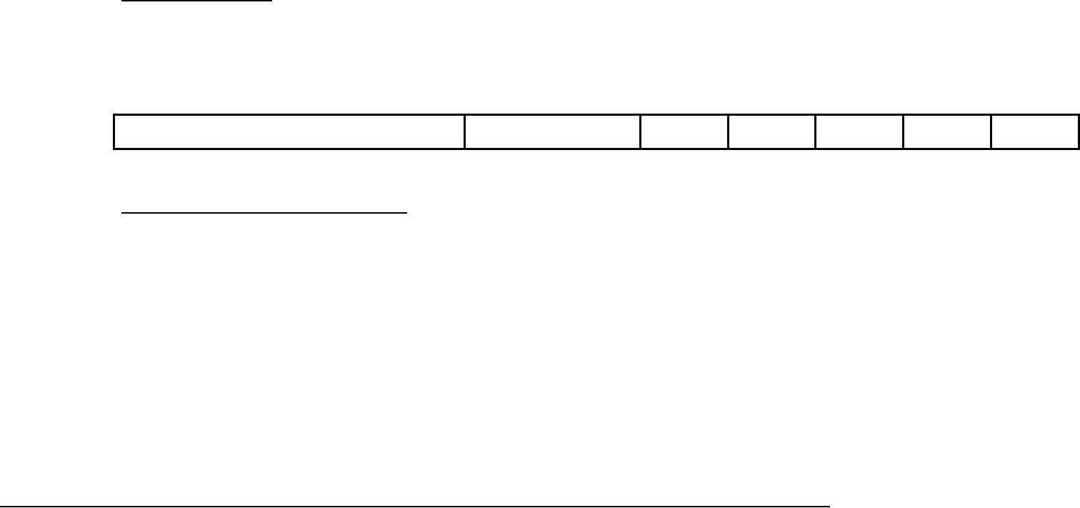
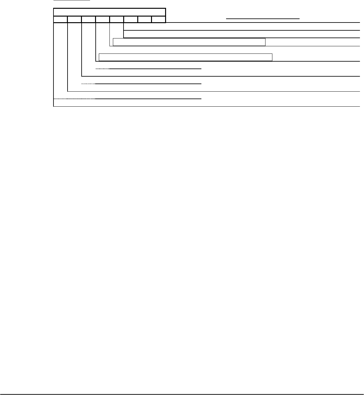
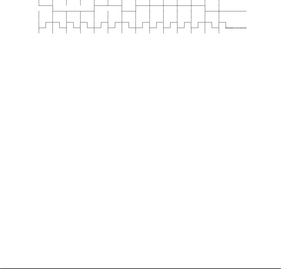
Timing Events versus Data Packet transmission for various operational situations:
3.4.2 Time Event / Data Packet Transmission Diagram
Te_2
--------------------------- // ------------------------ // ------------------ 60 seconds ---------------- // ------------------------ // -----------------
Te_1
- ~ 70ms -- //
~10ms~ Te_2a Te_3 ~10ms~ Te_3a, Te_1a
Make
Make
Break
Break Te_3b, Te_6a
Te_3c, Te_6a
Te_1a
Make
Make
Make
StkKy
Sleep
Te_4 - // ---- 70ms --- // ----- - // ---- 70ms -- // ----
Notes:
Te_4a Te_4b Te_5 Te_6
Time values are approximate and NOT to scale Te_5a Te_6a
Refer to APPENDIX for notation descriptions used in this Diagram and Table below.
Time Event / Data Packet Transmission
Time Event Key Press & Time Event Data Packet Transmission & Time Event Remark
Te_1
<K1> is pressed and detected
First Make-Code-Data-Packet (<K1> Scan Code) will be sent. It follows by
about 10 ms delay.
Te_2 <K1> key is still being
depressed
Second Make-Code-Data-Packet (of same <K1> Scan Code as above) will
be sent.
Case where a key press, <K1> say, is
detected. Make-Code-Data-Packets are
sent with 10 ms delay between the data
packets.
Te_4
Te_4a
Te_4b
70 ms after Te_2, <K1> is still
being held from the time event
Te_1 when the <K1> depress
is first detected..
Another 70 ms elapsed after
Te_4 and <K1> is still being
held down
<K1> is still being held down
70 ms after Te_4a.
Make code data packets of K1 are now transmitted.
Another Make code Data Packets are sent
Another Data Packet of Keep-Alive code is sent. See remark column.
This is the case where:
From the time event Te_1 and for
every 70 ms elapsed time interval, and
60 seconds stuck-key timeout has not
been reached, Make code Data-Packet
of the same key will be sent out as long
as key <K!> is still being held down.
Viewsonic Tweety RF Remote Rev 2.9A November 05, 2001
Universal Electronics Inc. Confidential Page 24 of 63
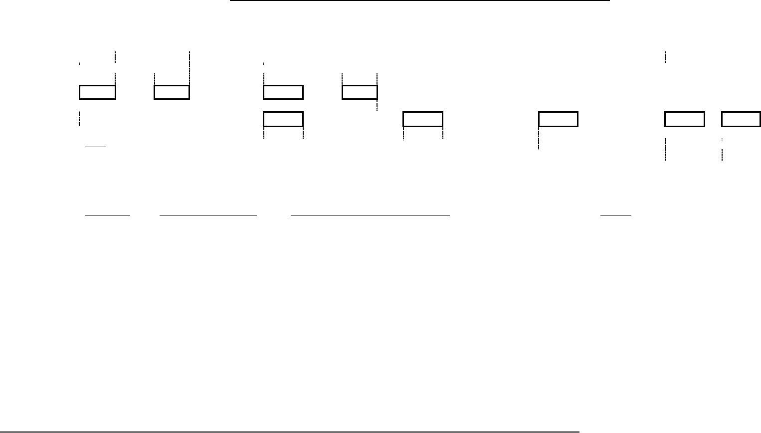
Time Event / Data Packet Transmission Diagram (continued)
Te_2
--------------------------- // ------------------------ // ------------------ 60 seconds ---------------- // ------------------------ // -----------------
Te_1
- ~ 70ms -- //
~10ms~ Te_2a Te_3 ~10ms~ Te_3a, Te_1a
Make
Make
Break
Break Te_3b, Te_6a
Te_3c, Te_6a
Te_1a
Make
Make
Make
StkKy
Sleep
Te_4 - // ---- 70ms --- // ----- - // ---- 70ms -- // ----
Notes:
Te_4a Te_4b Te_5 Te_6
Time values are approximate and NOT to scale Te_5a Te_6a
Refer to APPENDIX for notation descriptions used in this Diagram and Table below.
Time Event / Data Packet Transmission (continued)
Time Event Key Press & Time Event Data Packet Transmission & Time Event Remark
Te_3
Te_3a, Te_1a
Te_3b, Te_6a
Te_3c,
Te_5a
Te_6a
70 ms after Te_2a:
<K1> key is now released.
70 ms after Te_2a:
<K1> is released but another
key is pressed, <K2> say
within 5 seconds.
70 ms after Te_2a:
<K1> is released but NO other
key press detected after 5
seconds elapsed.
70 ms after Te_2a:
While <K1> is still being held
down, another key, <K2> say,
is pressed
Two Break-Code-Data-Packets (of <K1> Scan Code) will be sent, separated
by about 10 ms time interval between them.
Two Break-Code-Data-Packets (of <K1> Scan Code) sent with 10 ms
separation. The RF Transmitter will then be turned OFF. When another key,
<K2>, is pressed within 5 seconds, the RF Transmitter will be turned ON to
send two Make-Code-Data-Packets of K2 (10 ms between packets) as shown
at Te_1a
Two Break-Code-Data-Packets (of <K1> Scan Code) will be sent with 10
ms time delay in between when <K1> is released. Since no other key press
is detected beyond 5 seconds, a Sleep-Code-Data-Packet will be sent, the RF
transmitter will then be turned OFF to conserve the power.
Make code data packet of K1 sent as defined before. If <K1> released, Break code
data packets of K1 sent, 10 ms later, Make code data packet of K2 sent. If
<K2> is still down, Make code data packet of K2 sent, etc.. , until <K2>
released, then Break code data packet of K2 sent.
70 ms from the last Make-Code-Data-
Packet sent and <K1> released.
Case where <K1> released, and <K2>
pressed within 5 seconds after <K1>
released.
Case where <K1> released and no
other key press is to be followed after
more than 5 seconds.
Case of Sequence Break-
Code/Stuck/Sleep to indicate the
situation.
Viewsonic Tweety RF Remote Rev 2.9A November 05, 2001
Universal Electronics Inc. Confidential Page 25 of 63
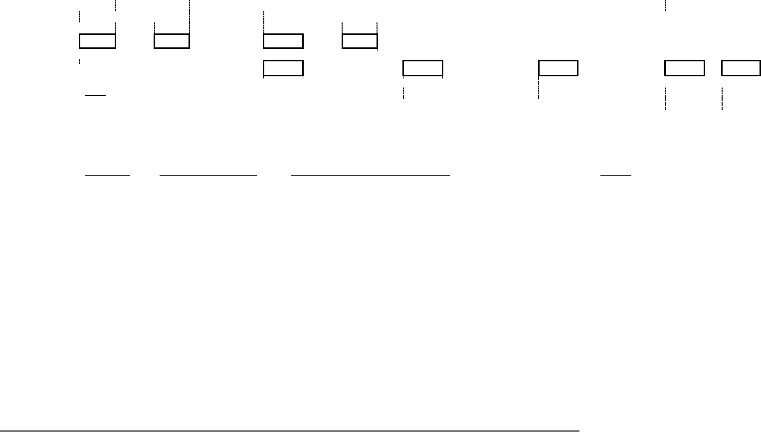
Key Type Data Packet Transmission, a Summary:
All keys including the pointing device buttons are Make/Break type. When a key or button is pressed, the remote will transmit the data packet as shown in the
protocol on previous pages.
For reliable data transmission, keystroke and control push buttons data packets are transmitted twice wirelessly from the Remote Control RF Transmitter. The
transmission is one time for Keep-Alive code and a minimum of 10 times for Re-Sync code.
MAKE 10ms MAKE BREAK 10ms BREAK
Followings are some scenarios of key press:
Case of a normal Key pressed/released:
Key Pressed Make Code sent.
Key Released Break Code sent, RF Transmitter turned OFF.
If no key press is detected after 5 seconds, RF Transmitter is turned ON and Sleep Code is sent. After that the RF
Transmitter is again turned OFF and the unit goes to SLEEP mode.
If a key press is detected within 5 seconds, that key data transmission will be serviced as described above.
If a key pressed then stuck for a long time, then Make Code of the same depressed key will be sent for every 70 ms time
interval within 1 minute from the time the original Make code sent. When 1 minute duration is expired, a Stuck code will be
sent, followed by Sleep code and the RF Transmitter is then turned OFF. Note that the software would only be able to go
to STOP (or SLEEP) mode when a stuck key is released.
Case of Make code kept resend (use <K1> and <K2> as an example):
<K1> pressed Make Code of K1 sent.
<K2> is then pressed while <K1> is still down and both keys are now down within 1 minute. The Make code of K1 will be
sent for every 70 ms time interval as described above, until one of the following conditions occurs:
<K1> is released first while <K2> is still held down. Break code of K1 will be sent and Make code of K2 will be
sent after 70 ms.
<K2> is released first while <K1> is still held down. Nothing changes except the same Make code of K1 will be
sent for every 70 ms time interval. Until <K1> is released and its Break code is sent.

Viewsonic Tweety RF Remote Rev 2.9A November 05, 2001
Universal Electronics Inc. Confidential Page 26 of 63
Case of Re-Sync data packet sent:
{{<Re-Sync>+<Digit>}} A <Digit> key is pressed while <Re-Sync> key is held down:
A minimum of 10 data packets of Re-Sync code (0x76) will be sent with 10 ms delay separated each data packet. Or the
Re-Sync data packets will be kept sending out as long as the keys are held down.

Viewsonic Tweety RF Remote Rev 2.9A November 05, 2001
Universal Electronics Inc. Confidential Page 27 of 63
APPENDIX
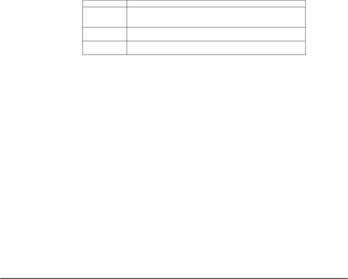
Some notations used in the Time Event / Data Packet Diagram
Notation Function Description
Make
Make Code for Scan Code of Keyboard Keypad or Remote Keypad, or X-
Coordinate, or Y-Coordinate of the Pointing Device
Break Break Code for Scan Code of Keyboard Keypad or Remote Keypad, or X-
Coordinate, or Y-Coordinate of the Pointing Device
ReSyn Make Code for Re-Sync
StkKy Make Code for Stuck-Key
Sleep Make Code for Sleep
Te_ij Time Event _ij, where i = 1, 2, 3, etc …
and j = nothing (empty) or a, b, c, etc …
<K1> First Key press in the sequence of key press events
<K2> Second Key press in the sequence of key press event after <K1>

Viewsonic Tweety RF Remote Rev 2.9A November 05, 2001
Universal Electronics Inc. Confidential Page 28 of 63
3.4.3 Device Number Setup
Note: To prevent possible interference from multiple users environment, each remote will be set to a specific User Device Number (User DN#, between 00 to
99). If the User DN# has not been setup, the OSD will prompt the user to program a device number setup.
To program, press <Re-Sync> key first then press <CH+> key, hold down both keys for about 3 seconds, then released:
<<Re-Sync> + <CH+>>
1. The software is now expecting the user to enter two digit numbers representing the device number by press/release <Digit> <Digit> keys. (In
the software test module, this process completes with 2 LED blinks indication).
2. If <AnyKey> key, other than <Digit> keys, is pressed after the above sequence, the software will abort the Device Number Setup mode. (In
the software test module, this error condition will be indicated by a long LED blink).
3. Within 10 seconds (timeout value) after the above sequence entry, if NO key is pressed (or the timeout expired between <Digit> key press),
the software will exit the Device Number Setup mode and the remote will retain the current settings. The software will then return to its normal
operation without having the device number updated. During this 10 seconds time, if the Pointer device is activated, the software will exit the
Device Number Setup mode and will service the pointer movement of the remote.
Each Remote has a Device ID and a Device Number (00-99). The Device ID shows the category of the Remote. The Host will validate the
received data packet from the Remote, by checking the Device Number, to see if it has been registered for that Device ID or not.
After the channel synchronization, the Device ID and Device Number of each Remote will be registered in the Host.
Note: For both Keyboard and Remote Control, the Keypad and Pointing Device have the same Device Number. During synchronization, only Device ID
of the Keypad and the Device Number of the Pointing Device will be sent. The Host should also register the Device Number for the Pointing Device of
the corresponding device.
Viewsonic Tweety RF Remote Rev 2.9A November 05, 2001
Universal Electronics Inc. Confidential Page 29 of 63
3.4.4 RF Channel Change
Re-Sync Data Packet
Byte10 Byte09 Byte08 Byte07 Byte06 Byte05 Byte04 Byte03 Byte02 Byte01 Byte0
(MSB)
0x0F
0x0F
0x0F
0x0F
0x55
0x55
0-0x63
(0-99
decimal)
0x00
0x76
(LSB)
0xYY
Sync Bytes
Preamble Device
Number
Dev Addr /
Status
X Coord Y Coord /
ScanCode
CheckSum
32 bits 16 bits 8 bits 8 bits 8 bits 8 bits 8 bits
How does the Re-Sync operates and When the “Re-Sync” code is sent:
Activating the <Re-Sync> key allows the user to send the “signature data” and to synchronize the RF Transmitter and Receiver RF-channel.
To activate the Re-Sync function:
Press <Re-Sync> key first.
While <Re-Sync> key is held down, press a digit key <d> where d is any digit keys from 1, 2, 3, …, 8, 9, 0 representing RF-channel 1, 2, 3, …,
8, 9, 10 respectively.
The process can pictorially be represented as below:
{{ <Re-Sync> + <d> }} <d> is <Digit> Key for Digit 1, 2, 3, …, 9, 0
Press/Release <d> key, while <Re-Sync> key is held down. The system first sets up “d” RF-channel for RF Transmitter (digit number
corresponding to channel 1 through 10), it then sends out the “Re-Sync” Make code data packet, minimum of 10 or more, as long as key still held
down.
If the <Re-Sync> and <d> keys are both
released
No Break Code data packet for “Re-Sync” will be sent. The “Sleep” code data packet will be sent
when no key activities are detected after 5 seconds (Refer to Sleep Code transmission section for
details).

Viewsonic Tweety RF Remote Rev 2.9A November 05, 2001
Universal Electronics Inc. Confidential Page 30 of 63
If another <Digit> key is
pressed/released while the <Re-Sync>
key is still held down
The system will setup another RF-channel, corresponding to that digit key, for the Transmitter, it then
sends out another “Re-Sync” Make code data packet in that RF channel setting.
This process will be repeating as above in response to different <Digit> key is pressed/released while
<Re-Sync> key is still held down.
This Re-Sync signature data transmission process will be repeated as described above each time another <Digit> key is pressed/released until
both Transmitter and Receiver units match its selected RF-channel. This channel frequency will then be used to transmit the data packet.

Viewsonic Tweety RF Remote Rev 2.9A November 05, 2001
Universal Electronics Inc. Confidential Page 31 of 63
3.4.5 E2 Initialization
EEPROM Initialization:
Note: The EEPROM device must have been previously initialized for the remote to be able to
get into the Factory RF Channel Test Mode.
Press <Re-Sync> key first then press <CH-> key, hold down both keys for about 3 seconds, then
released. The software will enter the E2 Initialization mode WHEN the <Enter> key is pressed
and released after the above described sequence.
<<Re-Sync> + <CH->>
1. If <Enter> key is pressed/released after the above sequence, the software will initialize
the EEPROM. (In the software test module, this process completes with 4 LED blinks
indication)
2. If <AnyKey> key, other than <Enter> key, is pressed after the above sequence, the
software will abort the EEPROM Initialization mode. (In the software test module, this
error condition will be indicated by a long LED blink).
Within 10 seconds (timeout value) after the above sequence entry, if NO key is pressed, the
software will exit the EEPROM Initialization mode and the EEPROM device will not be initialized.
The software will then return to its normal operation. But during this 10 seconds time, if the
Pointer device is activated, the software will exit the EEPROM Initialization mode and will service
the pointer movement of the remote.
Viewsonic Tweety RF Remote Rev 2.9A November 05, 2001
Universal Electronics Inc. Confidential Page 32 of 63
3.4.6 Factory Test Mode(s)1
To enter this RF Channel test mode, press and hold a combination keys <<1>+<3>> for at least 3
seconds then released, within 6 seconds after the battery/power is applied to the unit:
<<1> + <3>>2
The software will start with setting up RF-channel 1 and send through the Transmitter the entire
packet for the first channel continuously for the first 300 ms, with a 10-20ms gap between each
channel. The process is automatically with the next RF-channel setup until all 10 RF-channels
have been cycled through per Table1 below:
3.4.6.1 Table1: Factory Test Mode for RF Channel Test
Test Channel Time (ms) Packet Sent
0 - 300 0F 0F 0F 0F 55 55 FF FF 01 01 00
1 300 - 400 Nothing sent while changing RF Ch. 1
400 - 700 0F 0F 0F 0F 55 55 FF FF 02 02 02
2 700 - 800 Nothing sent while changing RF Ch. 2
800 - 1100 0F 0F 0F 0F 55 55 FF FF 03 03 04
3 1100 - 1200 Nothing sent while changing RF Ch. 3
1200 - 1500 0F 0F 0F 0F 55 55 FF FF 04 04 06
4 1500 - 1600 Nothing sent while changing RF Ch. 4
1600 -1900 0F 0F 0F 0F 55 55 FF FF 05 05 08
5 1900 - 2000 Nothing sent while changing RF Ch. 5
2000 - 2300 0F 0F 0F 0F 55 55 FF FF 06 06 0A
6 2300 -2400 Nothing sent while changing RF Ch. 6
2400 - 2700 0F 0F 0F 0F 55 55 FF FF 07 07 0C
7 2700 - 2800 Nothing sent while changing RF Ch. 7
2800 - 3100 0F 0F 0F 0F 55 55 FF FF 08 08 0E
8 3100 - 3200 Nothing sent while changing RF Ch. 8
3200 - 3500 0F 0F 0F 0F 55 55 FF FF 09 09 10
9 3500 - 3600 Nothing sent while changing RF Ch. 9
3600 - 3900 0F 0F 0F 0F 55 55 FF FF 00 00 FE 0
End test 3900 Nothing sent while changing RF Ch. 10
1FACTORY TEST MODE can be entered upon cold power up and/or warm power up
2 IF E2 is not initialized, the remote will not enter the FACTORY TEST MODE.
Viewsonic Tweety RF Remote Rev 2.9A November 05, 2001
Universal Electronics Inc. Confidential Page 33 of 63
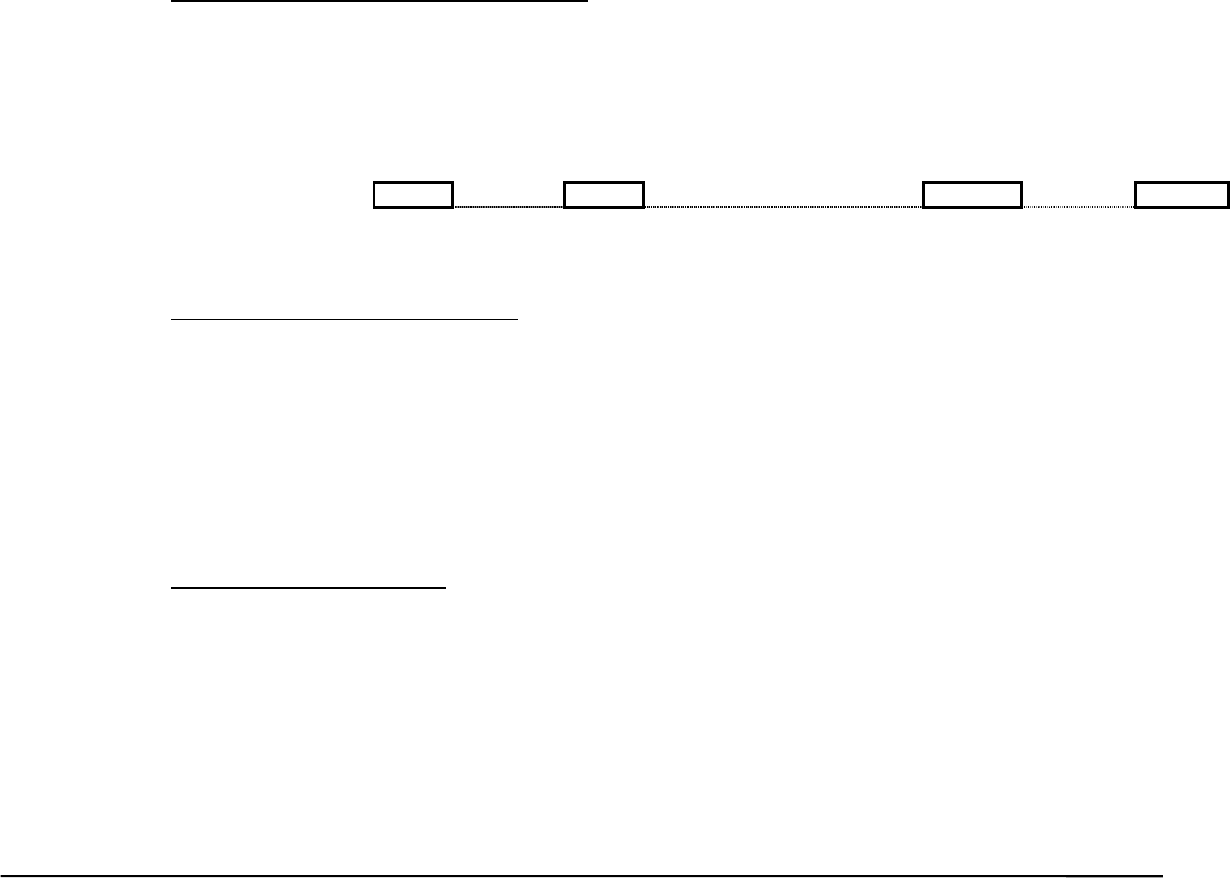
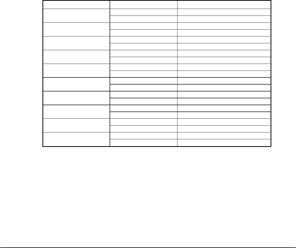
Key Test (Also used in Factory Test for Key):
An integrated hardware/firmware/software test unit will be designed for the Key Test. This Key
Test Unit can be used during this project software development as well as for factory test in an
actual production manufacturing. No special combination key sequence is required to get into this
Key Test mode.
The integrated Key Test unit is functionally represented as below:
TxD
------------------------------------------→
RxD
←------------------------------------------
+5V
---------------------------------------------
GND
---------------------------------------------
Firmware
Unit
Input:
Manchester
code from
RF Receiver
output
Output:
RS-232
Software
Unit
Input:
RS-232
Output:
Display on
Computer
Monitor
RS-232 interface (9600 baud)
RF
Receiver
Computer
Screen
Monitor
Viewsonic Tweety RF Remote Rev 2.9A November 05, 2001
Universal Electronics Inc. Confidential Page 34 of 63
3.4.6.1 Firmware Unit:
This so-called “unit” is actually a firmware portion that processes to keep 5 bytes of the 11-byte
data packet after striping off all the Sync bytes and Preamble bytes. It then output these 5 bytes
through the RS-232 protocol format.
Byte4 Byte3 Byte2 Byte1 Byte0
Device Number
DevAddr/Status
X-coordinate Y-coordinate /
Scan Code
CheckSum
(8 bits) (8 bits) (8 bits) (8 bits) (8 bits)
Byte0 CheckSum
The result of the addition (without carry) of Byte1 through Byte4
(Device Number + Device Address / Status + X-coordinate + Y-coordinate /
Scan Code)
Byte1 Y-coordinate / Scan Code
Y-data for Remote Control Pointing Device, or
Make/Break Scan Code of the pressed/released key on the Remote Control
Keypad. See Table2 for details.
Byte2 X-coordinate
X-data for Remote Control Pointing Device.
Always 0 for Remote Control Keypad
Byte3 Device Address / Status
Please refer to details on next page
Byte4 Device Number
Device Number is chosen from 0 to 99 by system Host interface. The Host
will validate the received data packet by checking the Device Number if it is
registered for that device.
Viewsonic Tweety RF Remote Rev 2.9A November 05, 2001
Universal Electronics Inc. Confidential Page 35 of 63
Byte3 details:
Device Address / Status
b7 b6 b5 b4 b3 b2 b1 b0
Details Byte3 Description
0 1 0 UEI Remote Control Keypad
1 0 0 UEI Remote Control Pointing Device
Pointing Device Left Button Status (0=Up, 1=Down)
Pointing Device Right Button Status (0=Up, 1=Down)
0 Positive
1 Negative
Sign Bit of X-coordinate
0 Positive
1 Negative
Sign Bit of Y-coordinate
0 OK, good
1 Low
Battery power level status
Viewsonic Tweety RF Remote Rev 2.9A November 05, 2001
Universal Electronics Inc. Confidential Page 36 of 63
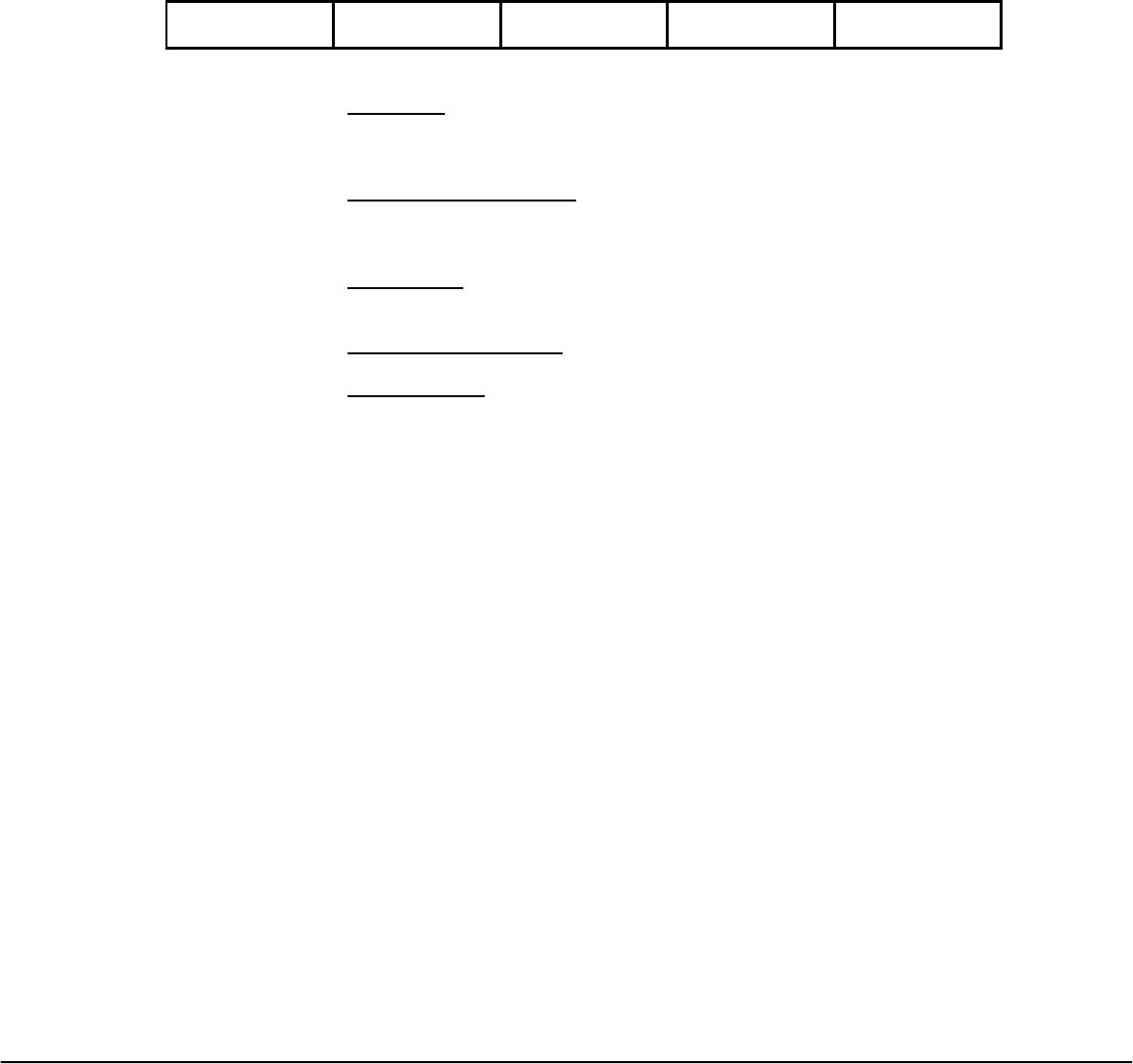
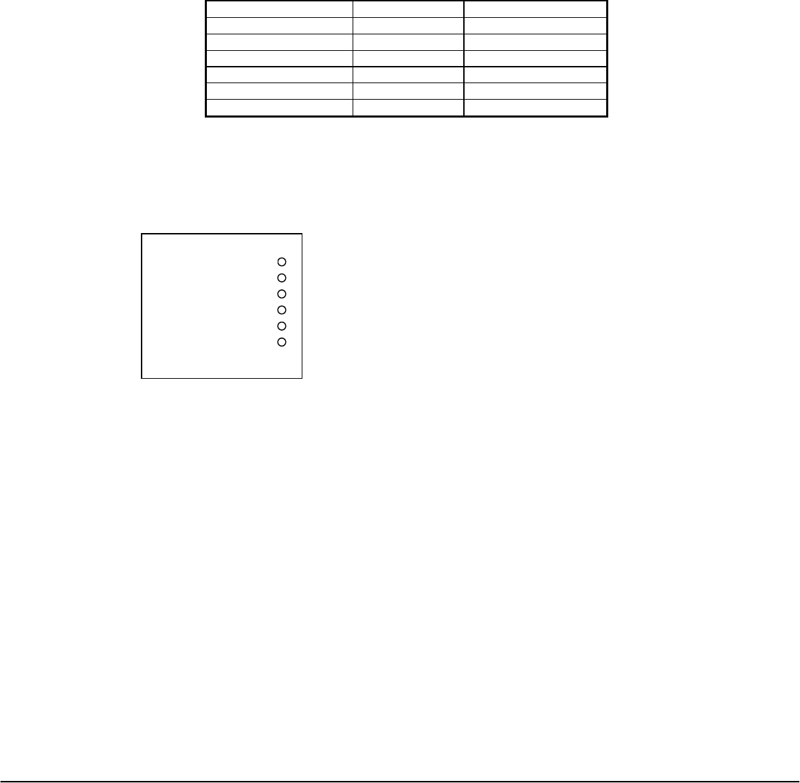
3.4.6.2 Software Unit:
This so-called “unit” is actually a software portion (in the integrated Key Test Unit). After it
receives a data packet of 5 bytes, as described above, through the RS-232 communication
protocol, it will display the output on the computer screen monitor. The display output information
will depend on the data input information received from the RS-232 inputs.
The display output will be designed as such:
• All 34 keys (Table2, columns 1 & 2) are to be programmed to be graphically displayed as key
buttons (with proper key label if possible). A color-coded scheme are to be designed to
visually represent the key status condition depending on (b2b1b0=010 in the Device Address
/ Status byte).
Color-coded Key press status
Gray
Indicates a key that had never been pressed and/or released, or
the key is malfunctioned that the remote could not detect when
pressed.
Red Indicates when the key is pressed and the software receives its
Make Code corresponding to that key.
Green Indicates when the key is released and the software receives its
Break Code corresponding to that key.
• Two allocated display locations on the screen monitor are to be programmed to show the
value of X-coordinate and Y-coordinate of the Pointing Device. These values are data
received in Byte2 and Byte1 when the pointing device on the remote control is activated
(b2b1b0=100 in the Device Address / Status byte).
• An allocated display location on the screen monitor is to be programmed to show the status
of the battery level condition. This status is to be decoded from bit b7 of Byte 3 (Device
Address / Status byte) in the received data packet.
• An allocated display location on the screen monitor is to be programmed to show the Device
Number. This value is to be extracted from Byte4 in the received data packet.
Viewsonic Tweety RF Remote Rev 2.9A November 05, 2001
Universal Electronics Inc. Confidential Page 37 of 63
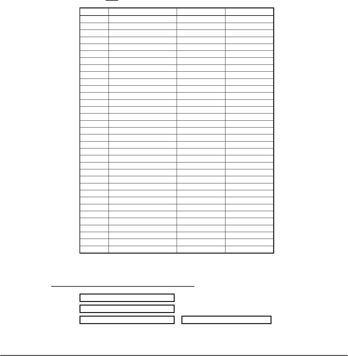
Table2: Key Test (Also used for Factory Key Test)
Note: Make Code and Break Code are in Hexadecimal.
Key # Key Label Make Code Break Code
1 POWER 75 F5
2 VL+ 74 F4
3 VL- 73 F3
4 MUTE 6B EB
5 CH+ 6F EF
6 CH- 70 F0
7 PREVIOUS 6D ED
8 MENU/EXIT 6E EE
9 PIP 6C EC
10 ENTER * *
11 SMART * *
12 REVERSE 57 D7
13 PLAY 58 D8
14 FFD 59 D9
15 RECORD 5A DA
16 STOP 5B DB
17 PAUSE 5C DC
18 INSTANT REPLAY 5D DD
19 JUMP COMM 5E DE
20 JUMP PRESENT 5F DF
21 EPG 60 E0
22 +100 61 E1
23 MULTIVIEW 62 E2
24 1 13 93
25 2 14 94
26 3 15 95
27 4 16 96
28 5 17 97
29 6 18 98
30 7 19 99
31 8 1A 9A
32 9 1B 9B
33 0 1C 9C
34 RE-SYNC 76 F6
* Set and Reset in Pointing Device Data Packet
Other allocated display locations on the screen monitor:
ID Number : xx
Battery Good / Battery Low
X-data of Pointing Device Y-data of Pointing Device

Viewsonic Tweety RF Remote Rev 2.9A November 05, 2001
Universal Electronics Inc. Confidential Page 38 of 63
3.4.7 Low Battery Indicator
When the batteries in the unit reach approximately 3.4 Volts the remote will send a specific frame
of data to indicate the remote batteries are low. The user will be prompted via an onscreen
display to change the batteries.
When the unit's batteries reaches 2.9 Volts +/- 200 mV the remote will not respond to key presses.
Viewsonic Tweety RF Remote Rev 2.9A November 05, 2001
Universal Electronics Inc. Confidential Page 39 of 63
4 RF Transmission General Specification
The performance requirements are contained in the table below
Table 2. General Specification
Rqmt No. Parameter Description Tx Module
4.1 Number of channels 10 channels
4.2 Channel spacing 1,2,3 & 1.6 MHz
4.3 Receive frequency band N/A
4.4 Demodulation N/A
4.5 Receiver sensitivity Minimum N/A
4.6 Data rate Fixed 9600 bps
4.7 Transmit frequency
band
2446.7 to 2464.3 MHz
4.8 Modulation FSK
4.9 Radiated power
FCC Requirements
Maximum
Fundamental
Spurious
emissions
-18 dBm
50 millivolts/meter @ 3
meters
500 microvolts/meter
@ 3 meters
4.10 Simplex type Transmit only
4.11 RF frequency tolerance ± 10 ppm
4.12 Temperature range Operating
Storage
0 to 50 °C
-10 to 60 °C
4.13 Power source Nominal 2.5 VDC
4.14 Power consumption Maximum
operational
supply current
15 mA
4.15 Dimensions 28mm x 22mm x 8mm
4.16 Weight To be determined
4.17 Other requirements PLL lock on time 50 ms
Note
* : The output data of channel 1-5 and channel 6-10 are different.
Channel 1~5 : Tx input data
Rx output data
Channel 6~10: Tx input data
Rx output data
Viewsonic Tweety RF Remote Rev 2.9A November 05, 2001
Universal Electronics Inc. Confidential Page 40 of 63
4.1 Data Coding
Data coding is necessary for the wireless communication, which is to eliminate the DC offset of the
demodulation caused by the series 1’s or 0’s. Following describes Manchester Coding implementation:
1 0 0 0 1 1 0 1 1 1 1 1 0
Viewsonic Tweety RF Remote Rev 2.9A November 05, 2001
Universal Electronics Inc. Confidential Page 41 of 63
5 Hardware Interface
The interface to the module shall be as described in the table below.
Table 1. Hardware Interface
Parameter Pin Number Tx Module
Input voltage - Vcc 1 2.2 volts
Ground 2 Ground
Data 3 Data input
Synthesizer enable 4 TTL input
Synthesizer SDA 5 TTL input
Synthesizer SCK 6 TTL input
5.1 Transmitter Outline /Interface
Dimension 28* 22*8 mm or smaller if 04/02 components are used
1. Vcc (2.2 V)
2. GND
3. Data in (Vp-p = 0.1V)
4. LE (TTL)
5. SDA (TTL)
6. SCK (TTL)
( Top View )
1
Viewsonic Tweety RF Remote Rev 2.9A November 05, 2001
Universal Electronics Inc. Confidential Page 43 of 65
5.1 Product Performance Requirements
5.1.1 RF CHANNEL and OPERATING BANDS
2400 to 2483.5 MHz
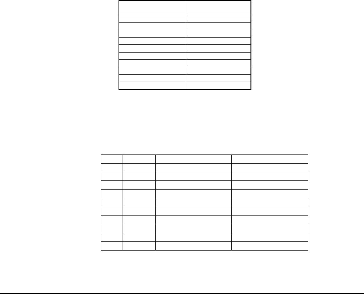
5.1.2 RF Channels and Frequencies
Channel Tx module transmit
frequency
1 2446.7 MHz
2 2448.7 MHz
3 2449.7 MHz
4 2451.7 MHz
5 2454.7 MHz
6 2456.3 MHz
7 2457.3 MHz
8 2459.3 MHz
9 2462.3 MHz
0 2464.3 MHz
Frequency Control
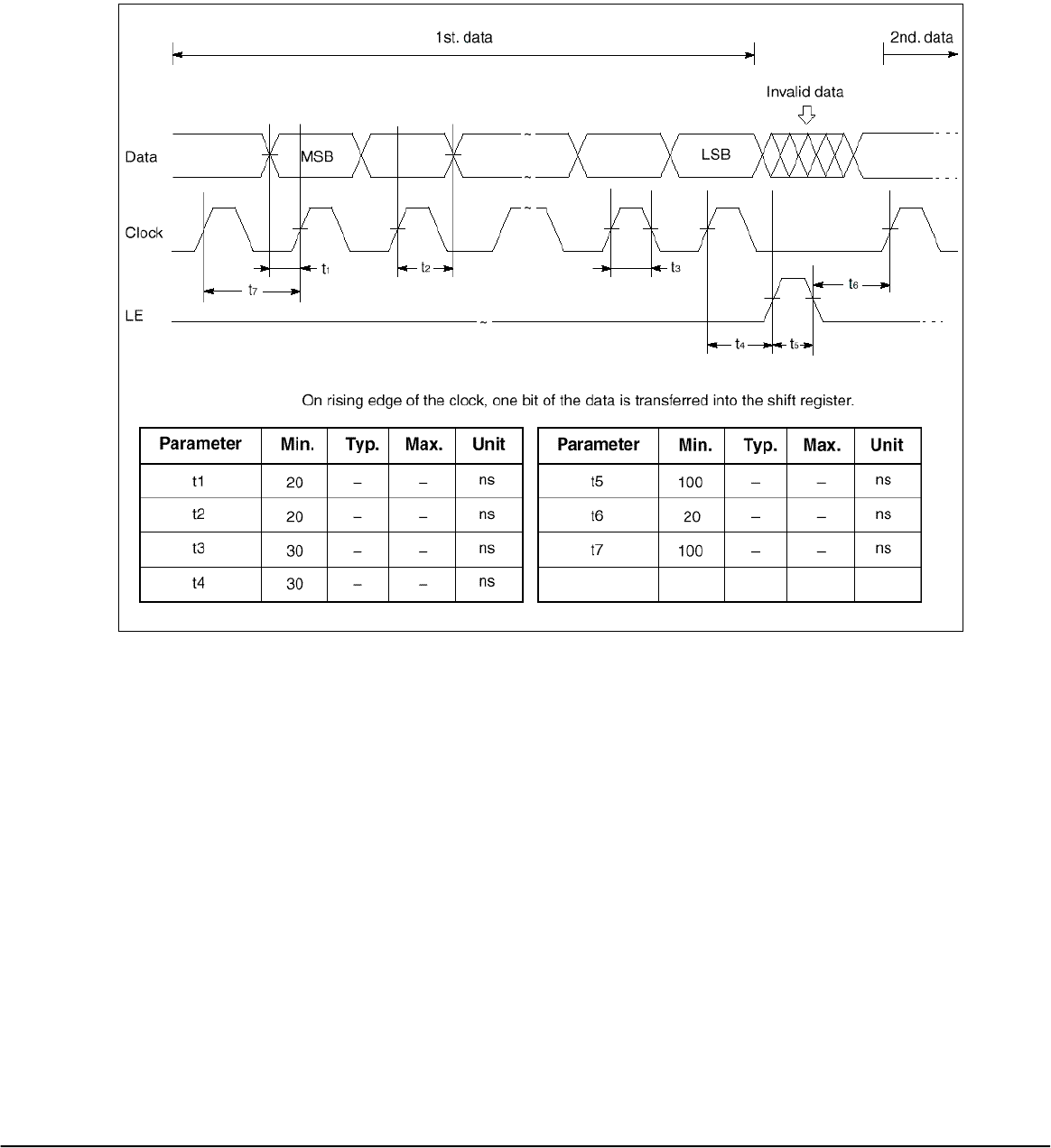
Serial data is processed using the SDA, SCK, LE pins. Serial data controls the RF module. Binary
serial data is entered through the SDA pin. One bit of data is shifted into the shift register on the
rising edge of the clock (SCK). When the load enable (LE) pin is high, stored data is latched. After
the both 19-bit register being latched, the frequency will be locked.
Transmitter
CH Freq. 19-bit Register 19-bit Register
1 2446.7 MHz 0010000000001010001 0010111111000100110
2 2448.7 MHz 0010000000001010001 0010111111001001110
3 2449.7 MHz 0010000000001010001 0010111111001100010
4 2451.7 MHz 0010000000001010001 0010111111010001010
5 2454.7 MHz 0010000000001010001 0010111111011000110
6* 2456.3 MHz 0010000000001010001 0010111111101100110
7* 2457.3 MHz 0010000000001010001 0010111111101111010
8* 2459.3 MHz 0010000000001010001 0010111111110100010
9* 2462.3 MHz 0010000000001010001 0010111111111011110
0* 2464.3 MHz 0010000000001010001 0011000000010000110
*Channels 6,7,8,9, and 0 will be inverted when transmitted.
Viewsonic Tweety RF Remote Rev 2.9A November 05, 2001
Universal Electronics Inc. Confidential Page 44 of 63
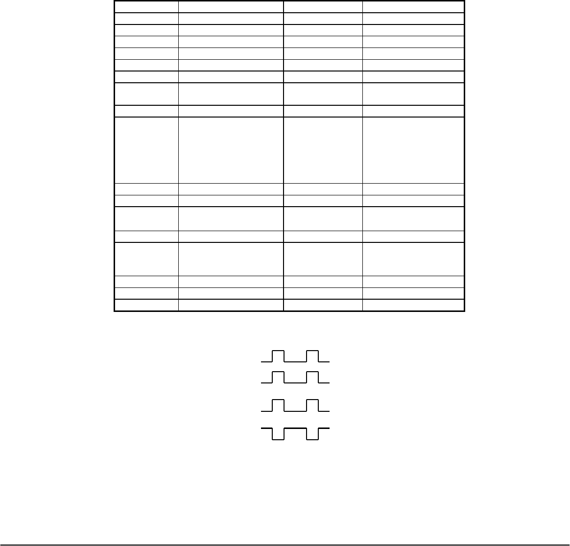
5.1.3 Pulse Width Timing for RF Transmitter
Long Low: 108.0us (+/- 5%)
Long High: 102.0us (+/- 5%)
Short Low: 53.0us (+/- 5%)
Short High: 50.0us (+/- 5%)
5.1.4 RF Channel Operation Range
The remote shall communicate at a minimum distance of 5m in a direct line of site
5.1.5 RF Modulation Scheme and Modulation Level
Modulation Scheme
Frequency Shift Keying (FSK
Modulation Level
± 70 kHz (Nominal)
5.1.6 Maximum Bit Rate
9600 baud (bps)
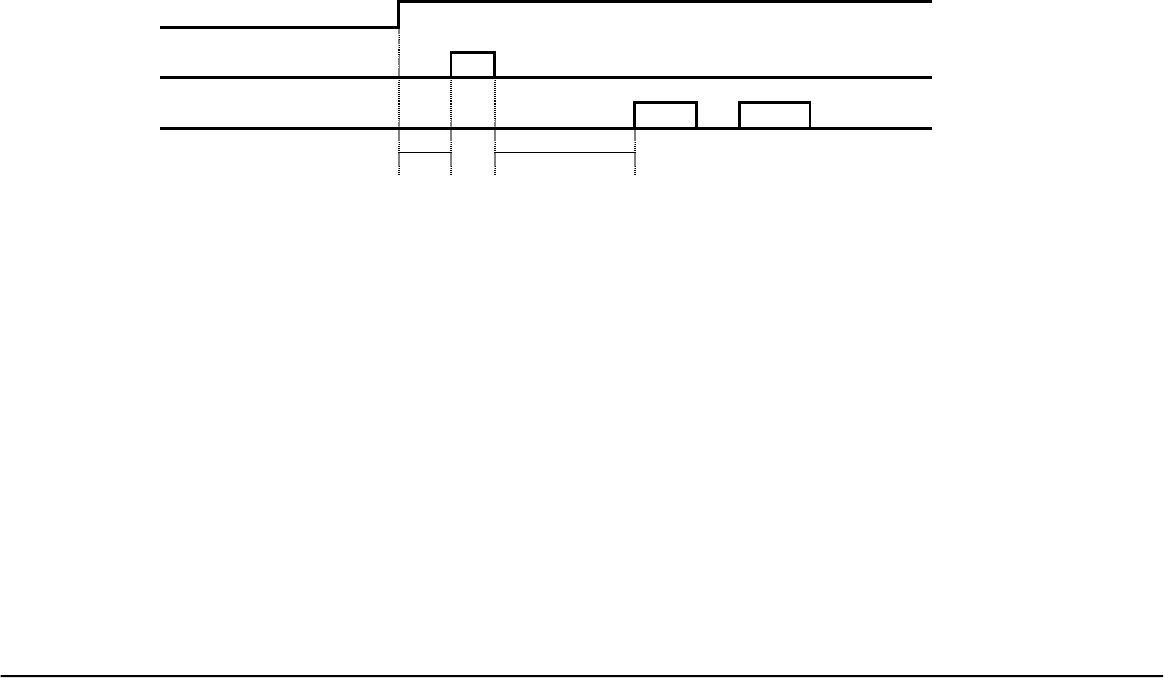
5.1.7 RF Power Management
RF Power On
Allocate Frequency X
Tx Data Input X X
T1 T2
• T1 = Power On Stable Time. Typically, it should be T1 > 5ms
• T2 = Frequency Stable Time. Typically, it should be T2 > 20ms
5.1.8 Transmitter Data Input Level
The transmitter data input level should be fixed as the supply voltage drops when using battery. It
is required that the Input level will be Vp-p = 100mv (+/- 10%).
5.1.9 Communication Link
Simplex – one way communication from remote control unit to base unit.
SERIAL INPUT DATA TIMING
Viewsonic Tweety RF Remote Rev 2.9A November 05, 2001
Universal Electronics Inc. Confidential Page 45 of 63

Viewsonic Tweety RF Remote Rev 2.9A November 05, 2001
Universal Electronics Inc. Confidential Page 46 of 63
6 Electrical Requirements
6.1 Power
The remote shall operate from (4 - AAA) alkaline batteries. Power requirements shall be a maximum
operating voltage of 6.4 volts.
6.2 Visible LEDs
NA
6.3 Transmission IC
Samsung 16K (S3P/C80F9XFE-QZR5) (QFP)
6.4 Battery Life
4 new AAA cells will provide approximately 10 months of battery life.
This is the time at which the remote will begin sending the specific
frame of data to indicate the remote batteries are low.
This assumes the following usage:
5 hours of operation per day
Approximately:
14.4 key presses per hour (@ 1 second each)
120 Seconds of Pointer operation per hour
6.5 Range
Minimum 5meters in direct line of site.

Viewsonic Tweety RF Remote Rev 2.9A November 05, 2001
Universal Electronics Inc. Confidential Page 47 of 63
7 Mechanical Requirements
7.1.1 HRC Assembly
The HRC assembly must meet UEI mechanical drawing and industrial design requirements.
7.1.2 Assembly LED’s
NA
7.2 Enclosure
7.2.1 Enclosure and Battery Cover Shape
The shape of the enclosing plastic parts including the top case, bottom case and
battery cover can be specified by a set of mechanical part drawings and CAD files in
the form of DXF and/or IGES format or Pro-E, Ashlar Vellum or AutoCAD format.
7.2.1.1 Part Form
All plastic parts must meet the shape and proportions embodied in their respective
UEI mechanical drawings and industrial designs.
7.2.1.2 Part Alignment & Mismatch
All plastic parts must align correctly as specified in the respective UEI mechanical
drawings.
7.2.1.3 Battery Cover
The battery cover shall be designed to have a minimal lateral movement in the
battery compartment and to disengage the latch mechanism at 700±300 grams.
7.2.2 Material
Recommended material selection for standard use plastic parts is ABS GPM,
ABS T- grade or other engineering approved resin. The properties are
described as follow:
Physical:
Specific Gravity, solid 1.02-1.05
Mechanical:
Tensile Strength 5,000-6,900 psi (35-50 MPa)
Tensile Modulus 260,000- 360,000 psi (1,800-2,500 MPa)
Flexural Strength 8,500-12,300 psi (60-85 MPa)
Flexural Modulus 270,000-380,000 psi (1,900-2,600 MPa)
Viewsonic Tweety RF Remote Rev 2.9A November 05, 2001
Universal Electronics Inc. Confidential Page 48 of 63
Impact:
Izod Impact @ 73°F 3.1-7.5 ft-lb/in (170-400 J/m)
Izod Impact @ -40°F 1.2-2.6 ft-lb/in (65-140 J/m)
Flame Class Rating:
UL94HB 0.0579-0.0630 in. (1.47-1.6mm)
7.2.3 Texture
Texture shall be Mold-Tech MT-11010 or UEI engineering approved
equivalent as follows:
UEI SPEC. HONG KONG CHINA SIN OR MEXICO KOREA
(MOLD-TECH) (YICK SANG) (HON NGAI) (PHILIPS) (KYUNG SUNG)
MT-11010 D-428 MK-111 9-410-UN-D249 K-112G
7.2.4 Color
The Pantone Matching System (PMS) will be used as the general UEI color standard. Refer to the
“Pantone Color Formula Guide 1000” for specific color selection and color coordination.
7.3 Keypad with Polydome
For further detailed information, see the UEI Keypad Design Guideline Manual
(Spec. # 0004).
7.3.1 Material
The keypad is usually molded from compression molded silicon rubber. The
recommended material shall be 50 to 60 shore A hardness, which provides good tactile
feel and long life.
Physical
Specific Gravity @ 25C 1.1-1.4
Durometer (Shore A) 55 ± 5
Tensile Strength 55 - 75 kg/cm2
Compression Set % 11 - 22
Insulation Breakdown 26 kV/mm
Flame Class Rating
UL94HB
The Polydome assembly is a die cut Polyethylene terephthalate (PET) sheets. It contains
0.05mm main dome sheet, adhesive, and 0.1mm spacer. The travel and tactile feed back
are provided by the main dome sheet.
7.3.2 Tactile Feel
The switch should operate smoothly throughout its entire travel with good tactile feedback.
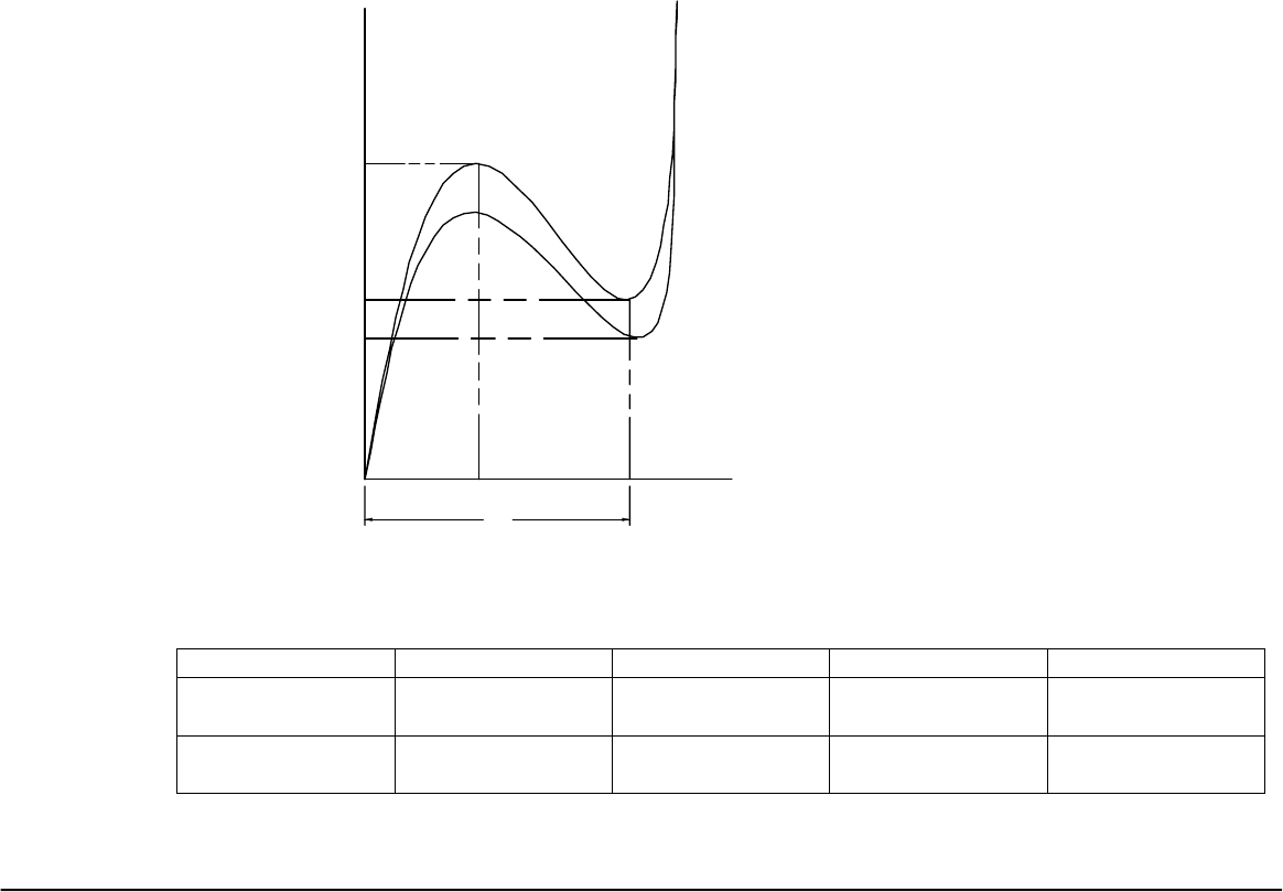
Viewsonic Tweety RF Remote Rev 2.9A November 05, 2001
Universal Electronics Inc. Confidential Page 49 of 63
7.3.3 Force Vs. Travel
The force values are represented by gram and the travel values are represented by
millimeter.
P1 (Peak force) = General range: 200±50 grams and it is dependent on specific
product application; therefore, see the keypad part drawing for
exact specification.
P2 (Contact force) = General range: 50-90% of P1.
PR (Return force) = 40 grams minimum.
S (Travel) = 0.4 ± 0.1mm and it is dependent on specific product
application; therefore, see the keypad part drawing for exact
specification.
PR
P2
P1
Travel (mm)
Force
(gram)
Figure 1: Force vs. travel
S
Peak force, P1 Return force, PR Snap ratio, TR Stroke, S
Rubber keypad
only
150±30 grams 40 grams minimum 40% to 60% 1.0±0.2mm
Keypad with
polydome
200±30 grams 40 grams minimum 40% to 70% 0.4±0.1mm

Viewsonic Tweety RF Remote Rev 2.9A November 05, 2001
Universal Electronics Inc. Confidential Page 50 of 63
7.3.4 Life
Key Pad with Polydome
All keys must continue operation within specification, after being subjected to500,000 cycles of
key activation at , 250 grams of force @ 120 cycles per minute under normal operating conditions.
7.3.5 Keypad Pull-out Force
The key top must not be separated from its base after 1kg vertical pull up force is applied.
7.3.6 Key stick and key stuck
All keys should rebound to their original height smoothly and instantaneously. All keys should
not get stuck under the key openings whichever location of the key is pressed.
7.4 PCB Material
Material specification needs to be provided to Engineering and approved by Engineering prior to
usage. Layout shall be based on UEI Specification 0029. If carbon ink is used, UEI Specification
0007 should be followed.
7.5 Battery Compartment
• The battery compartment must be clearly marked for battery size and polarity.
• The battery compartment must be designed to accommodate all brands per American National
Standard Dry Cell and Battery Specification (ANSI C18.1M-1992).
• The battery must be retained by coil or leaf springs, tight enough to avoid rocking and loose
enough for easy replacement.
• The battery compartment must be designed to prevent contact in case of reverse polarity
during installation.
• The batteries must remove from the battery compartment when a force of 300 to 500 grams is
exerted outward.
• The battery springs must be properly positioned to make contact with the batteries.
• The battery springs must remain properly seated when a force of 500 grams is applied.
• The battery springs must be insulated from each other.
7.6 Printing
A pad printing or silk-screening process shall be used for all legends that print on plastic surface. A
silkscreen printing process shall be used on keypad.
All printing shall be free of visible blurs, alignment, or any distortion defects. Ink thickness shall be
sufficient to cover the underlying material’s color.

Viewsonic Tweety RF Remote Rev 2.9A November 05, 2001
Universal Electronics Inc. Confidential Page 51 of 63
Key name Rubber Pantone color Case label text Key label
text
Case / Key label
Pantone Color
Power GS 056 European Power Symbol NMB White U
MENU/EXIT NMB Midnight Gray ABT 10936A MENU/EXIT NMB White U
VOL UP NMB Midnight Gray ABT 10936A VOL NMB White U
VOL DN NMB Midnight Gray ABT 10936A NMB White U
CH UP NMB Midnight Gray ABT 10936A CH NMB White U
CH DN NMB Midnight Gray ABT 10936A NMB White U
ENTER NMB Midnight Gray ABT 10936A ENTER NMB White U
SMART DS 161 SMART NMB White U
MUTE NMB Midnight Gray ABT 10936A MUTE NMB White U
PIP NMB Midnight Gray ABT 10936A PIP NMB White U
PREV CH NMB Midnight Gray ABT 10936A PRE CH NMB White U
REWIND NMB Midnight Gray ABT 10936A NMB White U
PLAY NMB Midnight Gray ABT 10936A 4 NMB White U
FAST
FORWARD
NMB Midnight Gray ABT 10936A NMB White U
RECORD NMB Midnight Gray ABT 10936A n Pantone 1788
STOP NMB Midnight Gray ABT 10936A g NMB White U
PAUSE NMB Midnight Gray ABT 10936A II NMB White U
INST
REPLAY
DS 161 INST REPLAY NMB White U
JUMP
COMM
DS 161 JUMP COMM NMB White U
JUMP
PRESENT
DS 161 JUMP
PRESENT
NMB White U
EPG DS 161 EPG NMB White U
+100 DS 161 +100 NMB White U
MULTIVIEW DS 161 MULTIVIEW NMB White U
1 NMB Midnight Gray ABT 10936A 1 NMB White U
2 NMB Midnight Gray ABT 10936A 2 NMB White U
3 NMB Midnight Gray ABT 10936A 3 NMB White U
4 NMB Midnight Gray ABT 10936A 4 NMB White U
5 NMB Midnight Gray ABT 10936A 5 NMB White U
6 NMB Midnight Gray ABT 10936A 6 NMB White U
7 NMB Midnight Gray ABT 10936A 7 NMB White U
8 NMB Midnight Gray ABT 10936A 8 NMB White U
9 NMB Midnight Gray ABT 10936A 9 NMB White U
0 NMB Midnight Gray ABT 10936A 0 NMB White U
RESYNC NMB Midnight Gray ABT 10936A RESYNC NMB White U
Housing will be NMB Midnight Gray ABT 10936A for top and back case.

Viewsonic Tweety RF Remote Rev 2.9A November 05, 2001
Universal Electronics Inc. Confidential Page 52 of 63
7.7 Labeling
7.7.1 Date Code
All assembly units require date code information. This information shall be marked inside the
battery compartment in a form hot stamp/cold stamp or label. The date code information contains
seven alphanumeric digits as describe below:
XXXXXXX
First Digit Factory code
Second and Third Digit Last two digits of year produced
Fourth and Fifth Digit Week # of year produced
Sixth and Seventh Digit Revision level of the latest Engineering BOM
Factory Code
A - Samjin
D - Kimex
E - WKK
G - Computime
J - Jetta
K - Jeckson
M - Philips Mexico
N - Sejin
P - Philips Singapore
S - SMK Mexico
U - Universal Electronics
Example: U001002
Factory: Universal Electronics
Year: 2000
Week: 10
BOM Rev.: 02
7.7.2 Part Number Label
All assembly units require a label with the appropriate URC number applied inside the battery
compartment, unless this URC number has been printed on the battery cover door per submitted
artwork.
7.7.3 Country of Origin
All assembly units require country of origin either embossed or printed on bottom case or battery
door (except units shipped to Europe).

Viewsonic Tweety RF Remote Rev 2.9A November 05, 2001
Universal Electronics Inc. Confidential Page 53 of 63
8 QUALITY
This section defines the appearance, cosmetic, and durability testing requirements for
plastic parts and assemblies, on all universal remote controls. However, when UEI
customer requirements mandate, stricter (tighter) evaluation and testing methods must be
used by the factory.
8.1 Appearance
The unit shall be constructed in accordance with the mechanical requirements set
forth in this section. These requirements must not be changed without written
approval of Universal Electronics Inc.
• Key height shall be from 1.8±0.2 mm above the surface of the plastic case
when in a static condition.
• The gap between key and plastic opening shall be 0.1mm minimum and
0.5mm maximum. (Suggested nominal gap 0.3 mm).
• The plastic cases shall mate accurately with minimal overhang. The
maximum allowable overhang from the top case to the bottom case is 0.2mm.
The maximum allowable overhang from the bottom case to the top case is
0.1mm.
• The plastic cases shall mate with a consistence gap around the peripheral.
The gap shall be within 0.2mm from its designed dimension.
8.2 Cosmetic
8.2.1 Evaluation Criteria
8.2.1.1 Evaluation Criteria
• Lighting to be directly overhead.
• Surface to be evaluated held at a 45° angle to the line of sight, at a distance of
51cm (20”) maximum to the center of surface.
• Unit under evaluation to be rotated 30° in both directions about the 45° inclined
axis.
8.2.1.2 Lighting
The light source shall be Cool White Fluorescent, non-directional at an
intensity of 1000±215 Lux (100±20 footcandles).
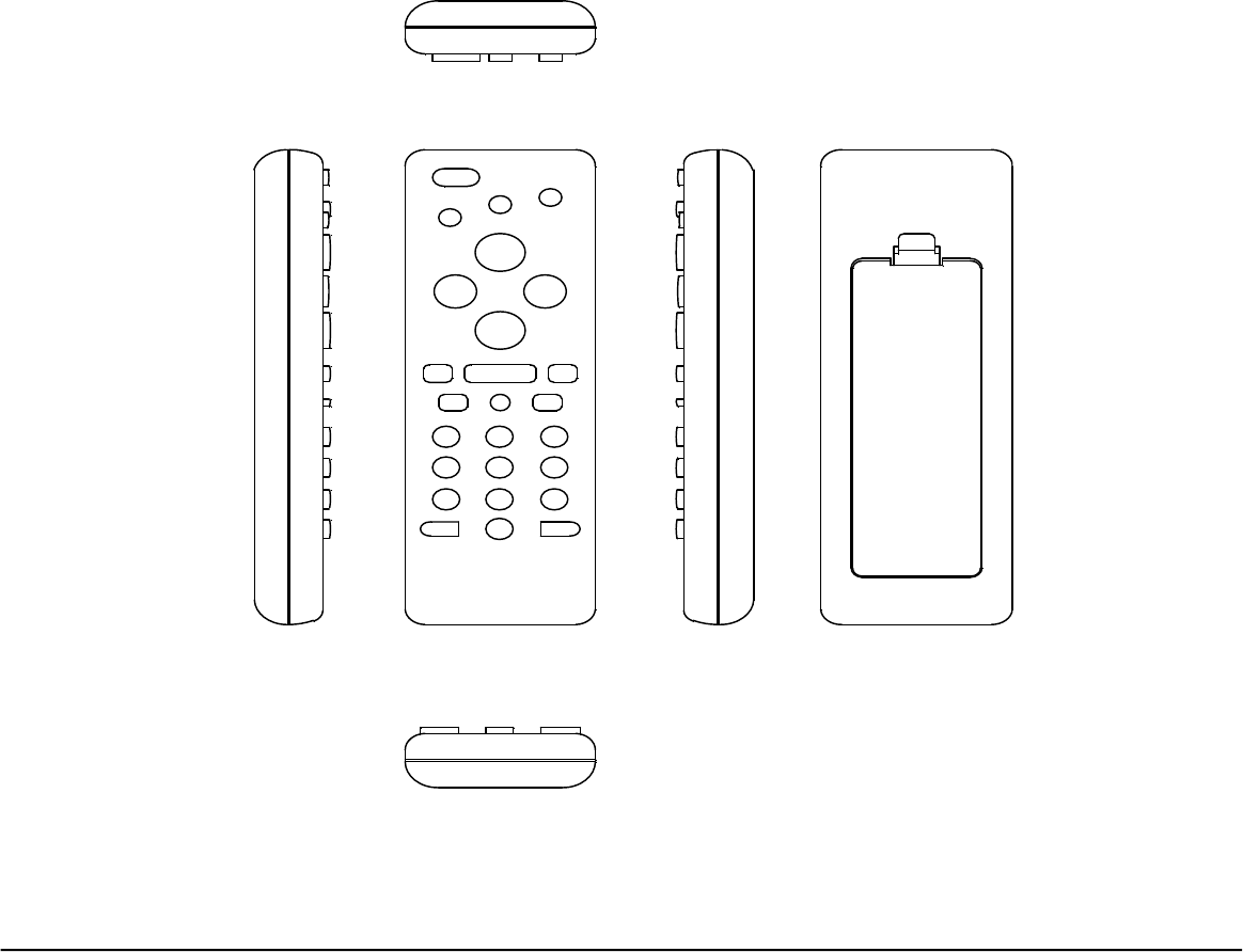
Viewsonic Tweety RF Remote Rev 2.9A November 05, 2001
Universal Electronics Inc. Confidential Page 54 of 63
8.2.2 Definition of Flaw and Defect
The cosmetic features are divided into two categories: Flaws and Defects
1) Flaw is an acceptable imperfection or blemish.
2) Defect is a flaw that exceeds the cosmetic limit.
8.2.3 Definition of Classes
Class I : The area usually viewed by user.
Class II: The area occasionally viewed by user.
Class III: The area seldom viewed by user.
Class II
Class II Class I Class IIIClass II
Class II
Fi
g
ure 2: Definition of Classes

Viewsonic Tweety RF Remote Rev 2.9A November 05, 2001
Universal Electronics Inc. Confidential Page 55 of 63
8.2.4 Cosmetic Evaluation
Part must not be "pre-inspected" at a distance closer than that allowed in the Viewing Angle and
Distance criteria.
8.2.4.1 All Classes
General: Blush marks, burns, pits, pulling, short shot, silver-streaks, slay, and weldlines
are not acceptable.
Cleanliness: Part must be free of dust, oil, grime, grease, and other contaminants. Dust
caused by shipping material is acceptable if it can be blown off by air or wiped
off.
8.2.4.2 Class I- Acceptable Flaws table
Maximum Inspection Time: 10 seconds
Type Size Qty
Parting Line Flash 0.15mm 1
Key Opening Flash 0.05mm per opening
Mismatch 0.15mm 1
Scratches (within texture depth) 1.5x0.2mm 3
Contamination 0.5mm 4
Sink not allowed
8.2.4.3 Class II- Acceptable Flaws table
Maximum Inspection Time: 5 seconds
Type Size Qty
Parting Line Flash 0.15mm 1
Mismatch 0.15mm 1
Scratches 2.0x0.2x0.3mm 4
Contamination 0.8mm 4
Sink 0.2mm 2

Viewsonic Tweety RF Remote Rev 2.9A November 05, 2001
Universal Electronics Inc. Confidential Page 56 of 63
8.2.4.4 Class III- Acceptable Flaws table
Maximum Inspection Time: 5 seconds
Type Size Qty
Parting Line Flash 0.15mm 1
Mismatch 0.15mm 1
Scratches 3.0x0.2x0.4mm 3
Contamination 1.0mm 4
Sink 0.5mm 3
8.2.4.5 Defects
• Any flaw that exceeds the limit of the above flaw table is a defect.
• Any two flaws on a given surface closer than 25mm is a defect.
• No more than three types of flaws are allowed on any one surface.
8.3 Durability Testing
8.3.1 Structure and Strength
• The plastic parts shall withstand a 5 kg compressive force for 3 seconds at several points
without any physical damage by using a Slimline force gauge McMaster P/N 1365T24 (See
Appendix, Figure C).
• The plastic parts shall withstand a bending force of 3 kg for 3 seconds applied at the ends of
the plastic assembly by using a Slimline force gauge McMaster P/N 1365T24 (See Appendix,
Figure D).
• The keypad buttons shall withstand a 3kg over activation load vertically for 3 seconds by
using a Slimline force gauge McMaster P/N 1365T24 (See Appendix, Figure E).
• The base of the keypad must not be exposed from the key opening after the 1.5kg lateral force
is applied by using a Slimline force gauge McMaster P/N 1365T24 (See Appendix, Figure F).
• The keypad shall not be damaged in normal operation using pen, pencil, or fingernail.
8.3.2 Printing
• All text printed on plastic surfaces or switch buttons must withstand normal shipping and
handling.
• All printed legends must pass the Scotch Super strength packaging tape (3M cat no. 3506) test.
Scotch tape is applied on the test surface and then removed three times at a 45° angle (each
time a new tape). The printing shall not exhibit evident defects such as flaking, chipping,
blistering, or de-lamination.
• All printed legends on plastic surfaces and keypad must be readable after being subjected to
500 cycles of abrasion @ 500 gram load with standard 100% cotton cloth as test piece.

Viewsonic Tweety RF Remote Rev 2.9A November 05, 2001
Universal Electronics Inc. Confidential Page 57 of 63
8.3.3 Battery Contact
• All forms of battery contacts, such as coiled spring and stamped spring, must not be
permanently deformed after the drop test.
• The batteries must remain in contact after being inserted/removed 20 times.
• The battery door must maintain its closing/latch integrity after being inserted/removed 20
times.
8.3.4 Painting wear test (if necessary)
The base plastic material cannot be shown after being subjected to 2000 cycles of abrasion @ 500
gram load with standard STAEDTLER eraser as test piece.
8.3.5 Rubber coating wear test (if necessary)
The base plastic material cannot be shown after being subjected to 2000 cycles of abrasion @ 500
gram load with standard STAEDTLER eraser as test piece.
8.3.6 Epoxy key test
8.3.6.1 Reliability tests
• Adhesion test (see Figure G):
The key with epoxy top will be cut 1mm between the epoxy top and silicon rubber, then
peeled off by finger. More than 50% of silicon must be attached to the epoxy top.
• Impact resistance test (see Figure H):
At room temperature, a 1.5-kg load will be dropped vertically onto the epoxy surface from
50cm high. There should be no visible crack or delamination.
• Ultra-violet resistance test:
The key with epoxy top will be tested per ASTM–D1148 method B for 2 hours. There
should be no sign of de-laminating, cracking or discoloration.
• Heat resistance test:
After the test-piece is exposed to 100°C for 12 hours, there should be no change of
transparency and color.
• Lateral load test (see Figure J):
There should be no delamination between the epoxy and the rubber key when 2-kg lateral
load at any point on the epoxy and rubber key common edge.
• Life test:
The key with epoxy encapsulated will be tested for 500,000 cycles with 250 grams force at 120 cycles
per minute. There should be no visible delamination.

Viewsonic Tweety RF Remote Rev 2.9A November 05, 2001
Universal Electronics Inc. Confidential Page 58 of 63
8.3.6.2 Cosmetic tests
See Section 6.2.1.
1. There should be no overflow larger than 0.15mm, and void (bubble) larger than
0.04mm.
2. There should be no visible scratch, crack, cloudy (milky) spot, foreign objects
such as fiber, dust, etc.

Viewsonic Tweety RF Remote Rev 2.9A November 05, 2001
Universal Electronics Inc. Confidential Page 59 of 63
9 ENVIRONMENTAL & SHOCK REQUIREMENTS
9.1 Temperature
Operating range:
0°C to +50°C
Non-operating range:
-10°C to +60°C
9.2 Humidity Test
The unit under evaluation will be exposed to 40±3°C, 95% relative humidity, non-
condensing for 24 hours without batteries or power. Functional tests will be performed
after the HRC has stabilized at normal room conditions for two hours.
9.3 Low Temperature Test
The unit under evaluation will be exposed to -20±3°C for 24 hours without batteries or
power. Functional tests will be performed after the HRC has stabilized at normal room
conditions for two hours.
9.4 High Temperature Test
The unit under evaluation will be exposed to 60±3°C for 24 hours without batteries or
power. Functional tests will be performed after the HRC has stabilized at normal room
conditions for two hours.
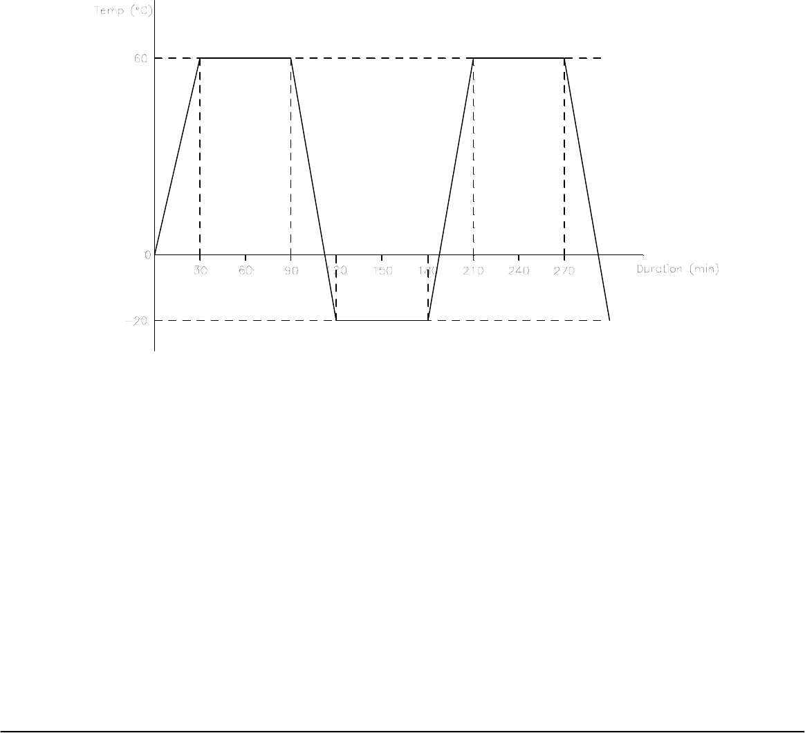
Viewsonic Tweety RF Remote Rev 2.9A November 05, 2001
Universal Electronics Inc. Confidential Page 60 of 63
9.5 Thermal Shock
The unit under evaluation (no batteries or power) will be subjected from -20°C to 60°C
for 5 cycles with a dwell time of 1 hour at high and low temperature (as shown below).
Functional tests will be performed after the HRC has stabilized at normal room
conditions for two hours.
9.6 Drop Test
The unit under evaluation must withstand one drop from 36 inches on six surfaces and
four corners onto hardwood flooring (suggested 0.75" thick oak). For further
specification details, see UEI Spec. #0005-0005.
For a product with three batteries or less, the battery door and batteries should not be
dislodged during the test.

Viewsonic Tweety RF Remote Rev 2.9A November 05, 2001
Universal Electronics Inc. Confidential Page 61 of 63
9.7 Solvent Resistance
The unit under evaluation shall not be deformed or disfigured in any way by the
application of 409 All Purpose Cleaner with 0.3% Alkyl dimethyl benzyl ammonium
chloride or Windex with Ammonia-D to any exposed surfaces. Caustic solvents and
cleaners such as porcelain, stainless, toilet or oven cleaners shall not be used. Apply two
(2) sprays of the cleaner directly onto any surface. The unit is then cleaned by wet towel
after five (5) minutes drying.
9.8 Liquid Spill
Eight (8) ounces of black coffee (no sugar added) will be poured over the keypad area
at an angle of 30 degrees inclined (normal remote holding position). The unit with
batteries installed is then turned up side down for five (5) seconds to allow coffee to
drip off. The test sample must function properly after 48 hours stabilization.

Viewsonic Tweety RF Remote Rev 2.9A November 05, 2001
Universal Electronics Inc. Confidential Page 62 of 63
10 Standard Compliances
10.1 ESD Protection
The HRC shall meet the following ESD profile per UEI Specification 0020 based on IEC 801-2.
10.2 FCC
Optoma will certify the complete unit with remote and keyboard.
With documentation and possible engineering support to Optoma from UEI.

Viewsonic Tweety RF Remote Rev 2.9A November 05, 2001
Universal Electronics Inc. Confidential Page 63 of 63
11 Rendering
INSTRUCTIONS MANUAL
FEDERAL COMMUNICATIONS COMMISSION
INTERFERENCE STATEMENT
This equipment has been tested and found to comply with the limits for a Class B digital
device, pursuant to Part 15 of the FCC Rules. These limits are designed to provide
reasonable protection against harmful interference in a residential installation. This
equipment generates, uses and can radiate radio frequency energy and, if not installed
and used in accordance with the instructions, may cause harmful interference to radio
communications. However, there is no guarantee that interference will not occur in a
particular installation. If this equipment does cause harmful interference to radio or
television reception, which can be determined by turning the equipment off and on,
the user is encouraged to try to correct the interference by one or more of the following
measures:
-- Reorient or relocate the receiving antenna.
-- Increase the separation between the equipment and receiver.
-- Connect the euipment into an outlet on a circuir different from that to
which the receiver is connected.
-- Consult the dealer or an experienced radio/TV technician for help.
CAUTION:
Any changes or modifications not expressly approved by the grantee of
his device could void the user's authority to operate the equipment.
The antenna(s) used for this transmitter must be installed to provide a separation
distance of at least 20 cm from all persons and must not be co-located or operating in
conjunction with any other antenna or transmitter. End-users and installers must be
provided with antenna installation instructions and transmitter operating conditions for
satisfying RF exposure compliance