VALEO Telematik und Akustik WMI2W167 Wireless Mobile Interface User Manual V1222 UserManual v1 8x
Peiker acustic GmbH Wireless Mobile Interface V1222 UserManual v1 8x
Contents
User Manual
________________________________________________________________________________________________________________________________
Page 1
VALEO – Product Line Valeo peiker Telematics - www.valeo.de
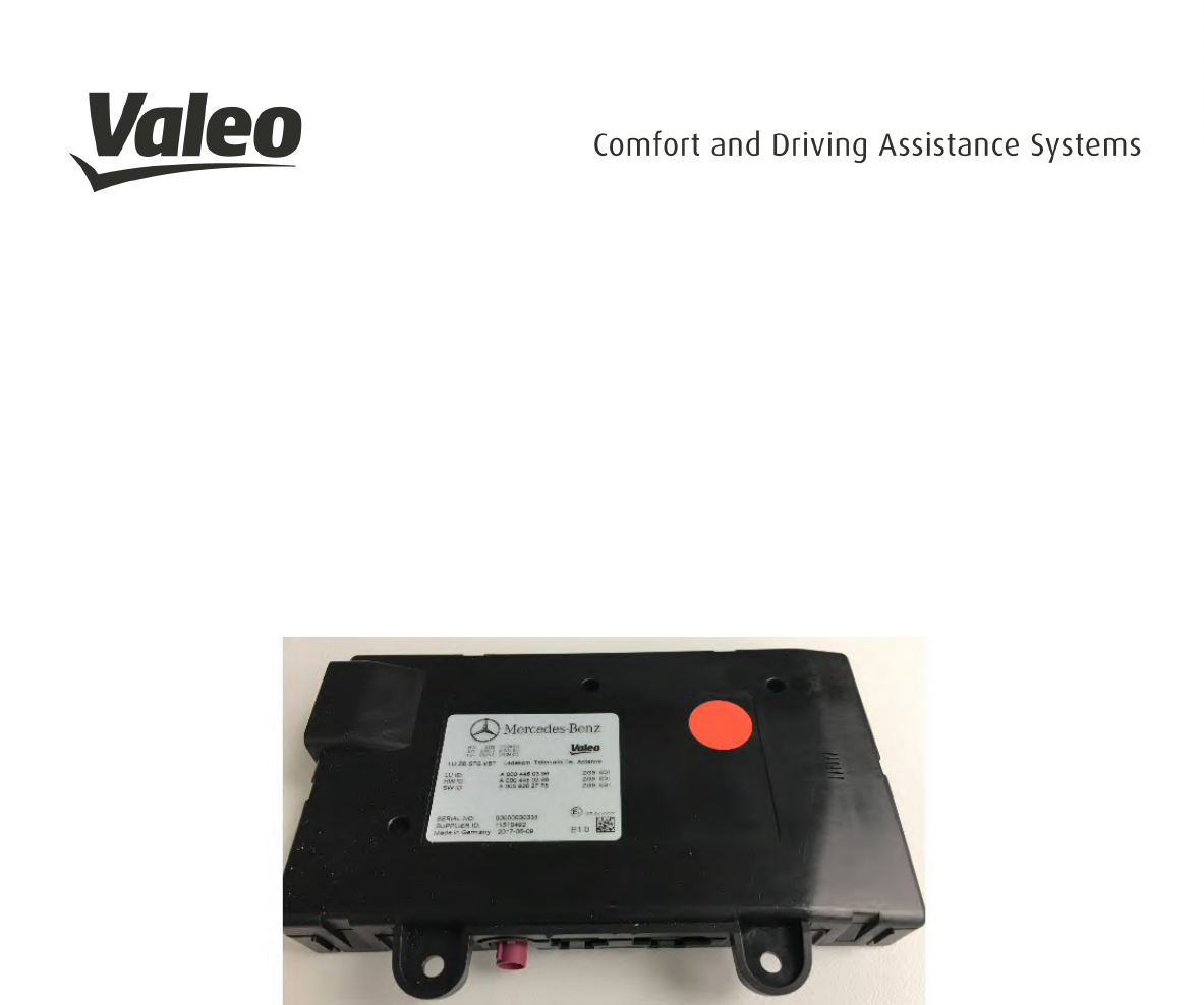
WMI 2
(wireless mobile interface)
User manual
Valid for Valeo Peiker product IDs:
WMI2-W167 2609-090-206-51 (trucks basic)
WMI2-W205 2609-090-306-51 (W205)
WMI2-W205-M1 2609-090-356-51 (W205 w/o)
WMI2-W167-M1 2609-090-406-51 (W167)
WMI2-W167-M2 2609-090-456-51 (W167 w/o)
WMI2-W167-M3 2609-090-556-51 (W167 Fd)
Revision: 1.7
Date: Jun 2018

________________________________________________________________________________________________________________________________
Page 2
VALEO – Product Line Valeo peiker Telematics - www.valeo.de
Revision History
Date
Revision
Name
Comment
13.12.2017
1.0 Uha Initial document
15.12.2017
1.2 Uha
19.12.2017
1.3 SSa Update serial numbers
19.12.2017
1.4 SSa Update point 3 & 4
10.01.2018
1.5 sho Update chapter 4.4 (distance from 20cm to 5cm), Insert FCC
Statements
15.01.2018
1.6 Uha Updates 2.3.1
06.06.2018
1.7 Uha Updates 2.9 Device detection mode
11.06.2018
1.8 Uha Updates 4.5 Further Notes

________________________________________________________________________________________________________________________________
Page 3
VALEO – Product Line Valeo peiker Telematics - www.valeo.de
Inhalt
1.
Introduction ............................................................................................................................................ 4
1.1
Scope ............................................................................................................................................... 4
1.2
Audience ......................................................................................................................................... 4
1.3
Contact information, Support .......................................................................................................... 4
2.
Product Overview ................................................................................................................................... 5
2.1
Product Variants .............................................................................................................................. 5
2.2
Technologies ................................................................................................................................... 5
2.3
Supported Technology/Frequency Bands ....................................................................................... 5
2.4
Features ........................................................................................................................................... 7
2.5
Equipment list: .............................................................................................................................. 10
2.6
Technical Setup ............................................................................................................................. 11
2.7
Computer Setup............................................................................................................................. 12
2.8
Operating Modes ........................................................................................................................... 18
2.9
Operational Modes Device Detection – Qi ................................................................................... 20
3.
Safety Recommendations according to EN62368-1 ............................................................................ 21
4.
RED / FCC / IC Regulatory Notices .................................................................................................... 22
4.1
Modifications ................................................................................................................................ 22
4.2
Interference ................................................................................................................................... 22
4.3
FCC Class B Digital Device ......................................................................................................... 23
4.4
OEM Responsibilties .................................................................................................................... 24
4.5
Further Notes................................................................................................................................. 24
________________________________________________________________________________________________________________________________
Page 4
VALEO – Product Line Valeo peiker Telematics - www.valeo.de
1. INTRODUCTION
1.1 SCOPE
This document gives an overview about electrical, mechanical and functional details of the Valeo peiker
WMI 2 wireless charging modules.
1.2 AUDIENCE
Information to integrate the module in some other applications.
1.3 CONTACT INFORMATION, SUPPORT
peiker acustic GmbH
Max-Planck Street 32
D-61381 Friedrichsdorf / Ts.
Germany
http://www.peiker.de
info@peiker.de

________________________________________________________________________________________________________________________________
Page 5
VALEO – Product Line Valeo peiker Telematics - www.valeo.de
2. PRODUCT OVERVIEW
2.1 PRODUCT VARIANTS
The WMI 2 module family consists of six variants:
Model-name Valeo Peiker product # Module configuration
WMI2-W167 2609-090-206-51 DAG trucks basic, with couple function
WMI2-W205 2609-090-306-51 DAG W205, with couple function
WMI2-W205-M1 2609-090-356-51 DAG W205, without couple function
WMI2-W167-M1 2609-090-406-51 DAG W167, with couple function
WMI2-W167-M2 2609-090-456-51 DAG W167, without couple function
WMI2-W167-M3 2609-090-556-51 DAG W167, fond variant, without couple function
2.2 TECHNOLOGIES
• Wireless charging equal to Qi Standard
• Connecting to device via NFC
• Proximity sensor description
• The device is detected by a ping algorithm via NFC
2.3 SUPPORTED TECHNOLOGY/FREQUENCY BANDS
2.3.1
Frequencies
NFC 13,56 MHz
Magnetic, modulated, according Qi Standard 1.0 125 kHz
o Downlink (from cell-phone/test receiver to WMI)
the receiver is using load modulation of 125kHz modulated with 2kHz to send
information to the WMI.
o Uplink (from WMI to cell phone/test receiver)
The WMI is using frequency modulation of the 125kHz to send information to the
receiver.
o Concerning wireless charging there is no other communication channel.
2.3.2
Data Rates
• CAN:
- 250kBaud
- 500kBaud

________________________________________________________________________________________________________________________________
Page 6
VALEO – Product Line Valeo peiker Telematics - www.valeo.de
• NFC:
- Modulated 115kBaud
- Modulated 230kBaud
- Modulated 440kBaud
2.3.3
Interfaces, customizable
• CAN
• SPI (internal)
Contact information, Support
2.3.4 Power level
• Charging mode
- Max power consumption 9,25 Watts each coil
- The device charge the mobile device with a power of 5 Watts
- The transfer system includes 3 coils. This includes charging systems that have three coils and
clients that are able to detect and allow coupling only between individual pairs of coils
- Only one coil is active
• Ping mode
- Max power consumption 0,25 Watts
2.3.5 Data Rates
• CAN:
- 250kBaud
- 500kBaud
• NFC:
- Modulated 115kBaud
- Modulated 230kBaud
- Modulated 440kBaud
2.3.6 Dimension and Weight
- Dimensions: 160mm x 95mm x 27mm
- Weight < 395 grams
2.3.7 Application
• Only vehicular Environment
The system is installed only in vehicles
2.3.8 Power
• Nominal voltage: 12V
• Max. current consumption: 0,8A
• Operating Voltage Range: 8V – 16V
________________________________________________________________________________________________________________________________
Page 7
VALEO – Product Line Valeo peiker Telematics - www.valeo.de
2.4 FEATURES
2.4.1 FBS (exchange of relevant security information)
2.4.2 Charging
2.4.3 Couple Function, passiv only
- Powerful application processor from NXP may contain and run complete application software
and CAN-software
2.4.4 Supply Voltage
Absolute minimum/maximum supply voltages 8V – 16V
Nominal supply voltage
12V
Recommended supply voltage
12V
Voltage drop @ GSM power burst (33dBm)
< 100mV
2.4.5 Power Consumption
T
A
= +25°C, P = 9,25W
2.4.6 Environmental Specification
2.4.7 Temperature Range
Range
Operating temp.
range
-
20°C … +60
°C
Wireless Charging
Extended o
perating temp.
range
-
20°C … +80°C
Operational
CAN communication
Storage temp. range
-
40°C … +85°C
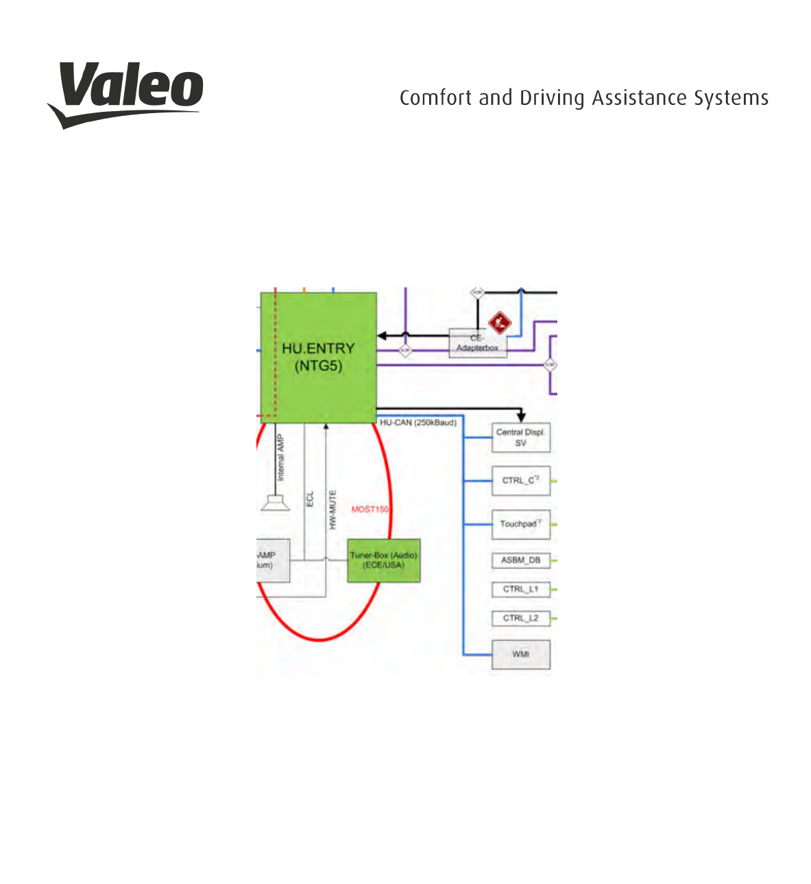
2.4.8 Connectors, external interfaces
The WMI is connected with a permanent 12V and the CAN bus, various control signals from the
CAN bus control the WMI and thus bring it into different working modes. In terms of driving
readiness, the WMI represents an interface between the head unit (Can with 250kBaud) and a
standard mobile phone from the driver of the vehicle. To support NFC telematics functions
including identification and data transmission to the vehicle head unit, for example for data
exchange with NFC vCards.

________________________________________________________________________________________________________________________________
Page 8
VALEO – Product Line Valeo peiker Telematics - www.valeo.de
To support these functions, there is a coupling antenna in WMI that fulfills the following functions:
• Interface to the GSM mobile phone via the coupling antenna
• Interface to the NFC enabled mobile phone via the internal NFC antenna
• Interface to the vehicle antenna via the GSM plug connection
2.4.9 NFC vs. Charging
While entering the vehicle and putting down the mobile on to the WMI the mobile will initiate to
the WMI (start of system), while transferring some CAN commands from the car to the WMI.
During the misalignment of the NFC-antenna, no specific NFC-Commands will be send.
Once activated, the WMI tries to detect any device, if an object was placed on the surface. After
a succesful detection of a Qi device, the system switch to Qi-detection-mode.
If the detection-mode has found a mobile with Qi-standard charging possibility on the WMI, the
power contract is established and a charging process will start. If the mobile is removed during
charging from the WMI, charging process is stopped immediately.
The WMI was designed following the Qi standard to charge mobiles prepared for Qi-
charging. Current versions of the WMI do not fulfill the whole Qi-standard, therefore no Qi Logo
is declared on the WMI and no Qi-certification exists.
2.4.10 Module Pin-out
Table 1 Module Pin-out
MWCT1014S Signal name
(used in the schematic) Description
Port /
Pin
Selected
function
PTB4 /
28 PTB4
µC2NFC-DWL-REQ
Active state: High level
After a reset the NFC controller NCF3340 starts
the download mode sequence.
Passive state: Low level
After reset no download sequence will be started
by the NFC controller
PTD10 /
36 PTD10
LED-ON-FEHLER
Active state: High level
The LED on the Debug PCB is switched on
Passive state: Low level
The LED on the Debug PCB is switched off
PTD11 /
35 PTD11
LED-ON-LADEN
Active state: High level
The LED on the Debug PCB is switched on
Passive state: Low level
The LED on the Debug PCB is switched off

________________________________________________________________________________________________________________________________
Page 9
VALEO – Product Line Valeo peiker Telematics - www.valeo.de
MWCT1014S Signal name
(used in the schematic) Description
Port /
Pin
Selected
function
PTE3 /
18 PTE3
µC2NFC-ANT-CTRL
Active state: High level
The RF input of the NCF controller NFC3340
(IC16) is connected to the external NFC antenna
Passive state: Low level
The RF input of the NCF controller NFC3340
(IC16) is connected to the internal NFC antenna
PTA14 /
88 PTA14
Capsensor2µC-EN
Active state: High level
A change in capacitance on the sensing plates is
detected.
Passive state: Low level
PTE14 /
17 PTE14
SW-MODE
Default state: High level
Alternative state: Low level
Note: Pins should be grounded when not used in design.
_____________________________________________________________________________________________________________________________
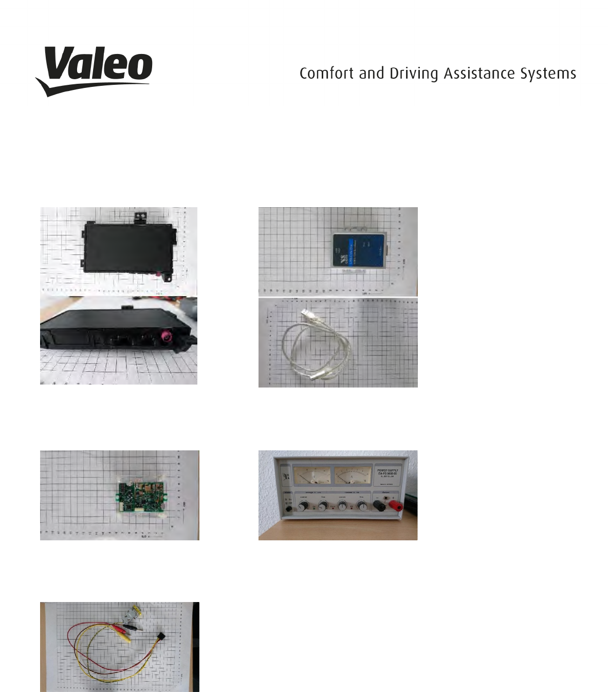
2.5 EQUIPMENT LIST:
Wireless Charger
Chargeable Wireless Medium
NXP LDO 1500 Test Receiver or
AVID Test Receiver
System Harness
_____________________________________________________________________________________________________________________________
VALEO – Product Line
Valeo peiker Telematics
USB Can Adapte
Voltmeter & Power Supply
_____________________________________________________________________________________________________________________________
___
Page 10
Valeo peiker Telematics
- www.valeo.de
_____________________________________________________________________________________________________________________________
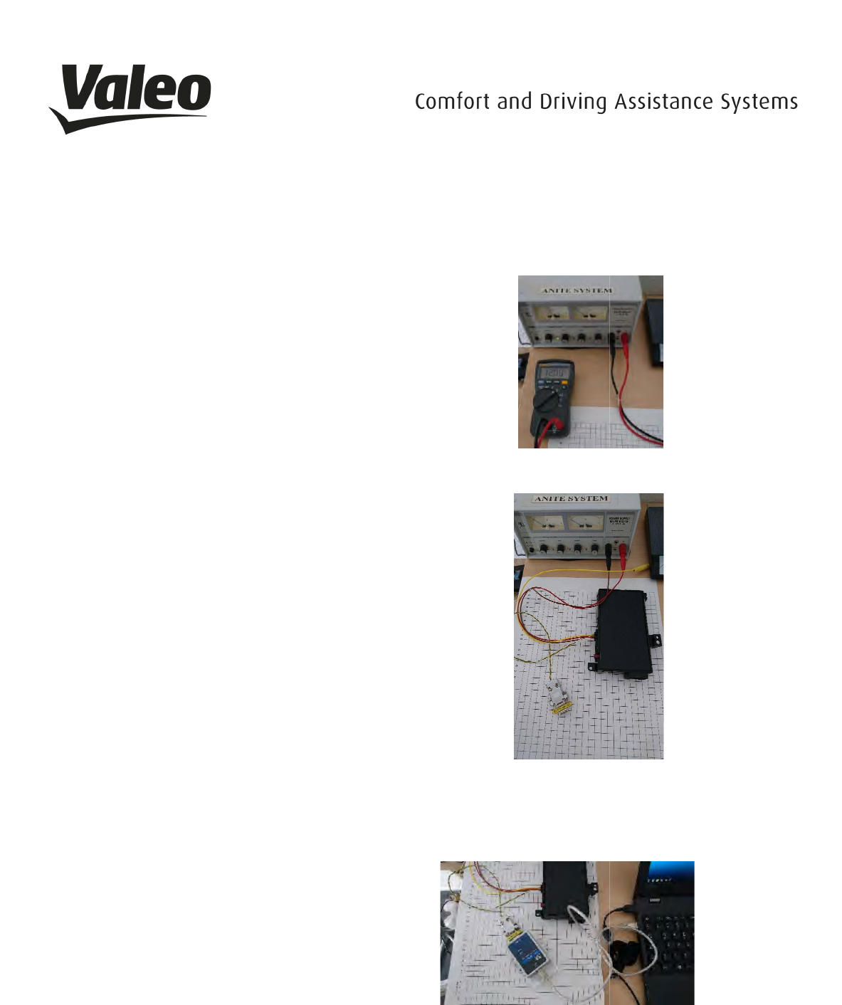
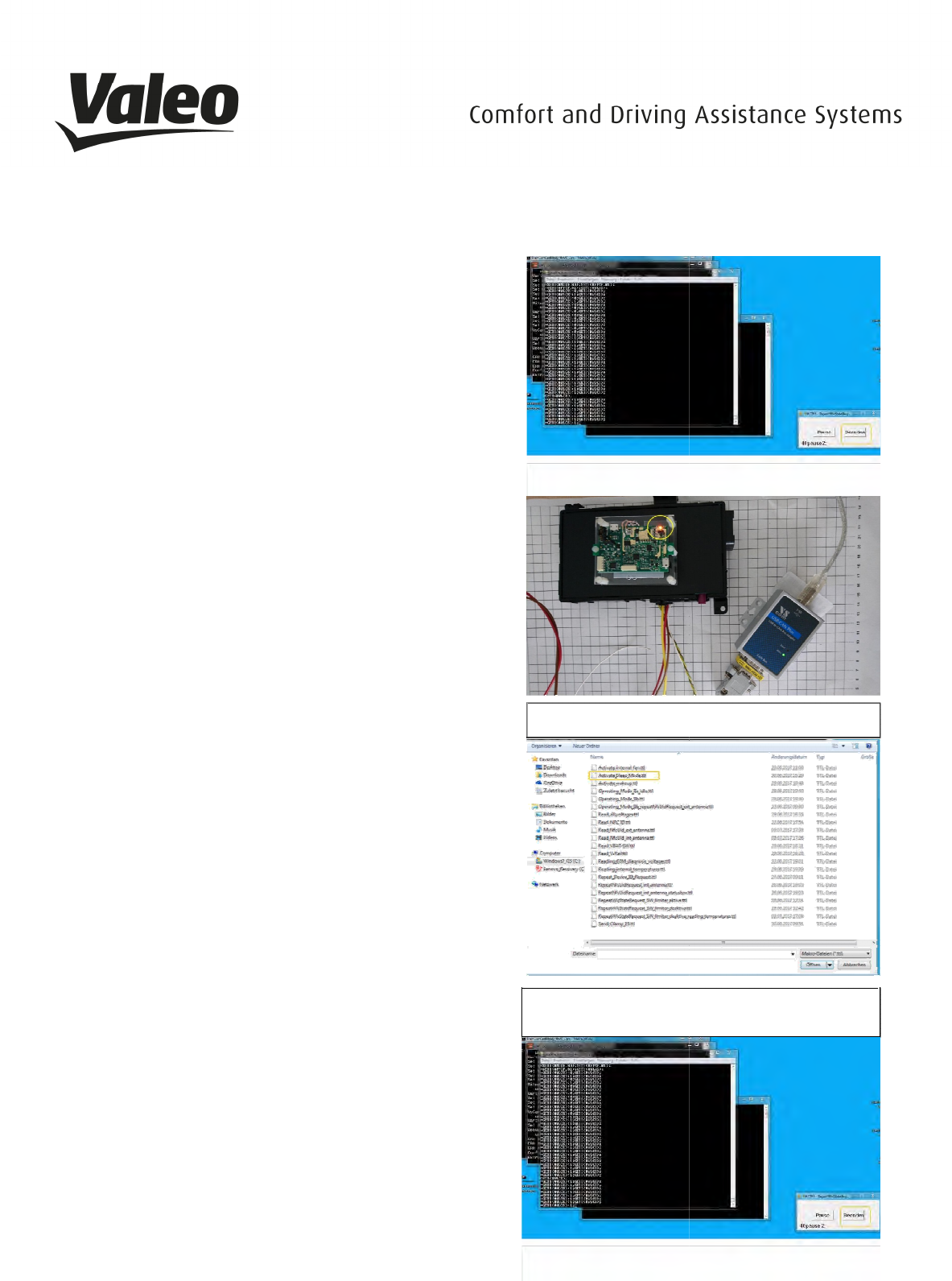
2.6 TECHNICAL SETUP
Pre-Caution:
Before testing the unit make sure that the
doesn´t exceed a voltage over 12V to avoid short
Connect the wireless charger with the power supply system
by using the red and black cables (the yellow cable is
irrelevant).
Connect the wireless charger with the
adapter via the green/yellow cable.
Connect the USB Can adapter with a computer.
Turn on the power supply system.
Note: The LEDs of the CAN-
Adapter are going
on and off
several times. This process is uncritical
_____________________________________________________________________________________________________________________________
VALEO – Product Line
Valeo peiker Telematics
Before testing the unit make sure that the
power supply system
doesn´t exceed a voltage over 12V to avoid short
-circuit.
Connect the wireless charger with the power supply system
by using the red and black cables (the yellow cable is
Connect the wireless charger with the
USB Can
Connect the USB Can adapter with a computer.
Adapter are going
several times. This process is uncritical
_____________________________________________________________________________________________________________________________
___
Page 11
Valeo peiker Telematics
- www.valeo.de
_____________________________________________________________________________________________________________________________
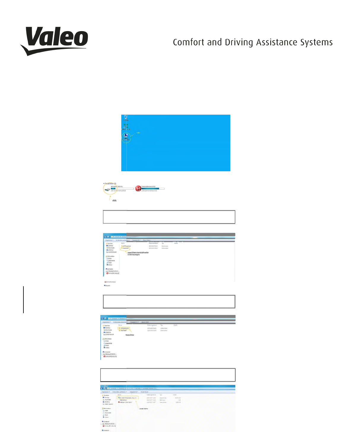
2.7 COMPUTER SETUP
Note:
Ideal is the use of a Windows 7 as 64
Open the Computer >> Connection
Open the Windows7_OS hard drive
Open the WMI folder
Install Busmaster driver
Go back into WMI
and open the
_____________________________________________________________________________________________________________________________
VALEO – Product Line
Valeo peiker Telematics
Ideal is the use of a Windows 7 as 64
-bit system
Open the Computer >> Connection
Open the Windows7_OS hard drive
Open the WMI folder
and open the
EVTP_test_tool_folder
_____________________________________________________________________________________________________________________________
___
Page 12
Valeo peiker Telematics
- www.valeo.de
_____________________________________________________________________________________________________________________________
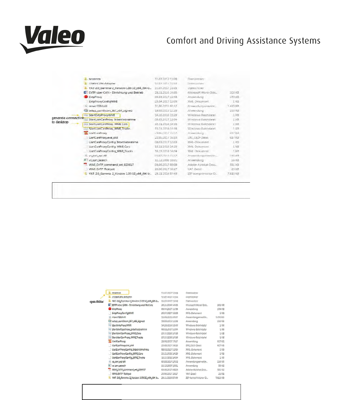
G
enerate connection to desktop
Note for
setup_com0com_W7_x64_signed
CNCB0 for Win 7 32-
bit system. A driver can be found in the internet
Note for
StartUart CanProxy_WMI_Cars
205 (cars) etc...) please use either the cars or the truck files
Note for
UartCanProxyConfigWMI_Cars:
_____________________________________________________________________________________________________________________________
VALEO – Product Line
Valeo peiker Telematics
enerate connection to desktop
setup_com0com_W7_x64_signed
: Please install the virtual comport driver only for CNCa0 and
bit system. A driver can be found in the internet
StartUart CanProxy_WMI_Cars
:
Depending on the device (W167 (trucks), W167
205 (cars) etc...) please use either the cars or the truck files
UartCanProxyConfigWMI_Cars:
Please use the newest version
_____________________________________________________________________________________________________________________________
___
Page 13
Valeo peiker Telematics
- www.valeo.de
: Please install the virtual comport driver only for CNCa0 and
Depending on the device (W167 (trucks), W167
-M1 (cars),
_____________________________________________________________________________________________________________________________
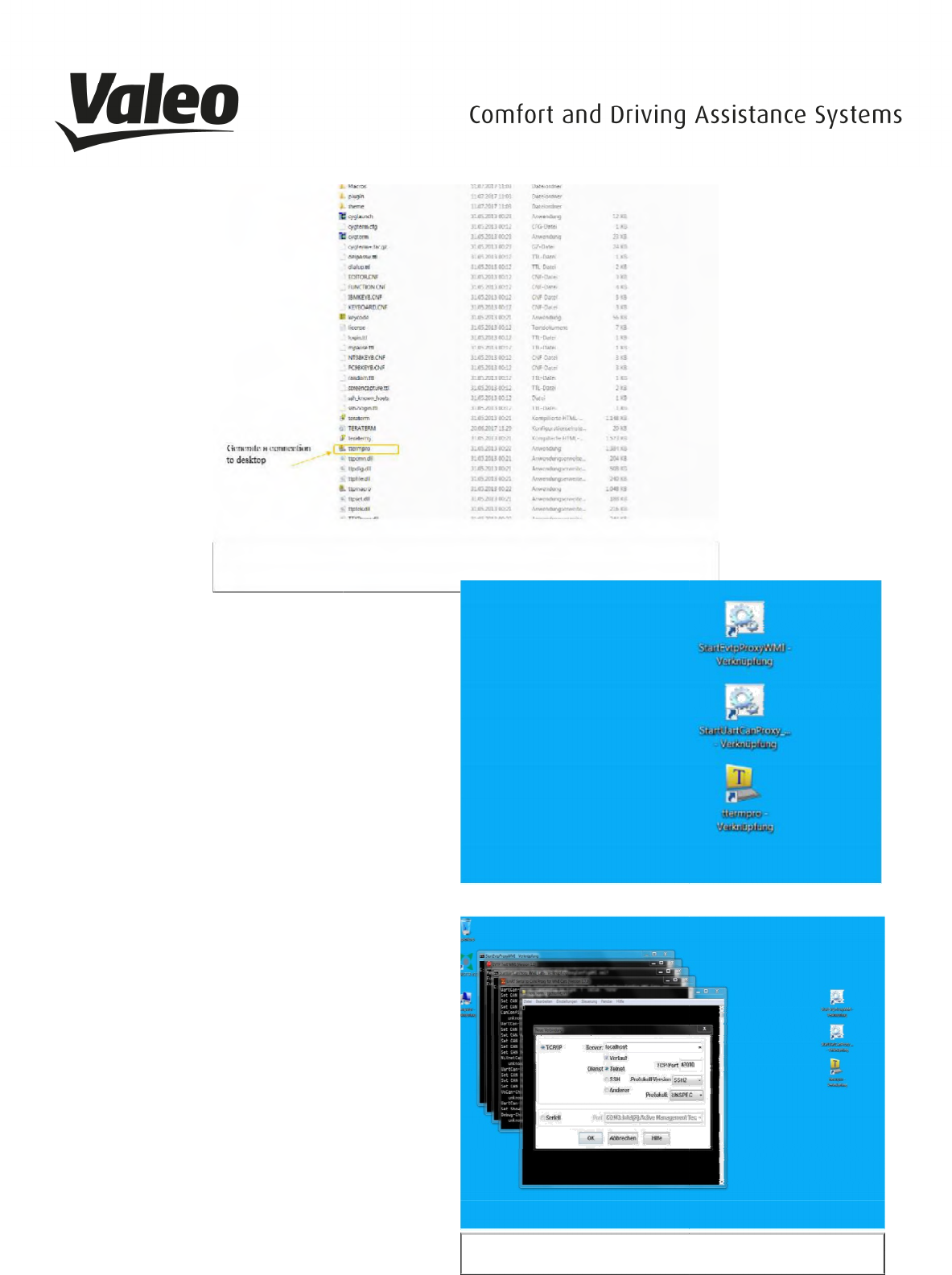
Open folder
teraterm
Generate a connection to desktop
Please start with the
StartEvtpProxy WMI
Depending on the device, please start with
StartUartProxy as 2nd
Please start ttermpro as last
All Programs stay unclosed
Open the tools successively in following order:
StartEvtpProxyWMI
_____________________________________________________________________________________________________________________________
VALEO – Product Line
Valeo peiker Telematics
teraterm
StartEvtpProxy WMI
first
Depending on the device, please start with
Open the tools successively in following order:
StartUartCanProxy ttermrpo
_____________________________________________________________________________________________________________________________
___
Page 14
Valeo peiker Telematics
- www.valeo.de
StartUartCanProxy ttermrpo
and press OK afterwards
_____________________________________________________________________________________________________________________________
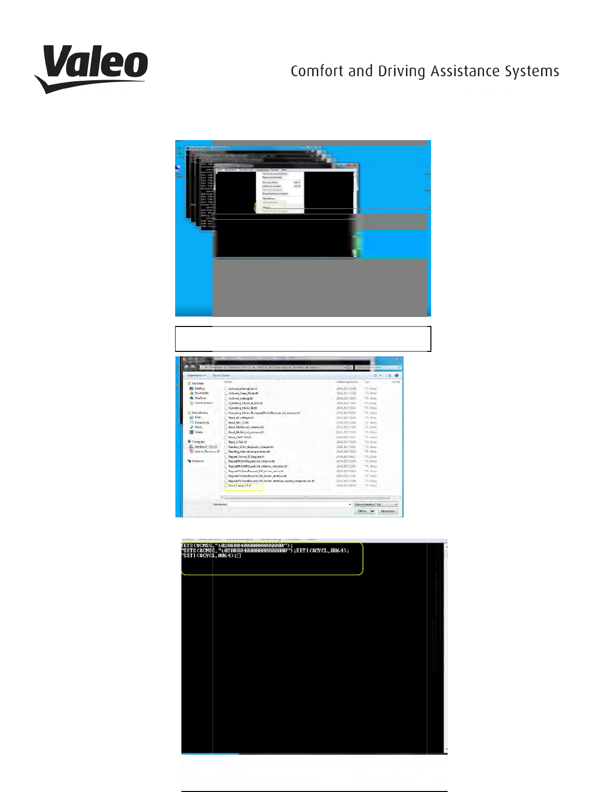
Click on navigation and afterwards
the macro menu
Open
Send_clamp_15ttl
_____________________________________________________________________________________________________________________________
VALEO – Product Line
Valeo peiker Telematics
Click on navigation and afterwards
open
the macro menu
Send_clamp_15ttl
Attention: wait until the third line appears
_____________________________________________________________________________________________________________________________
___
Page 15
Valeo peiker Telematics
- www.valeo.de
_____________________________________________________________________________________________________________________________
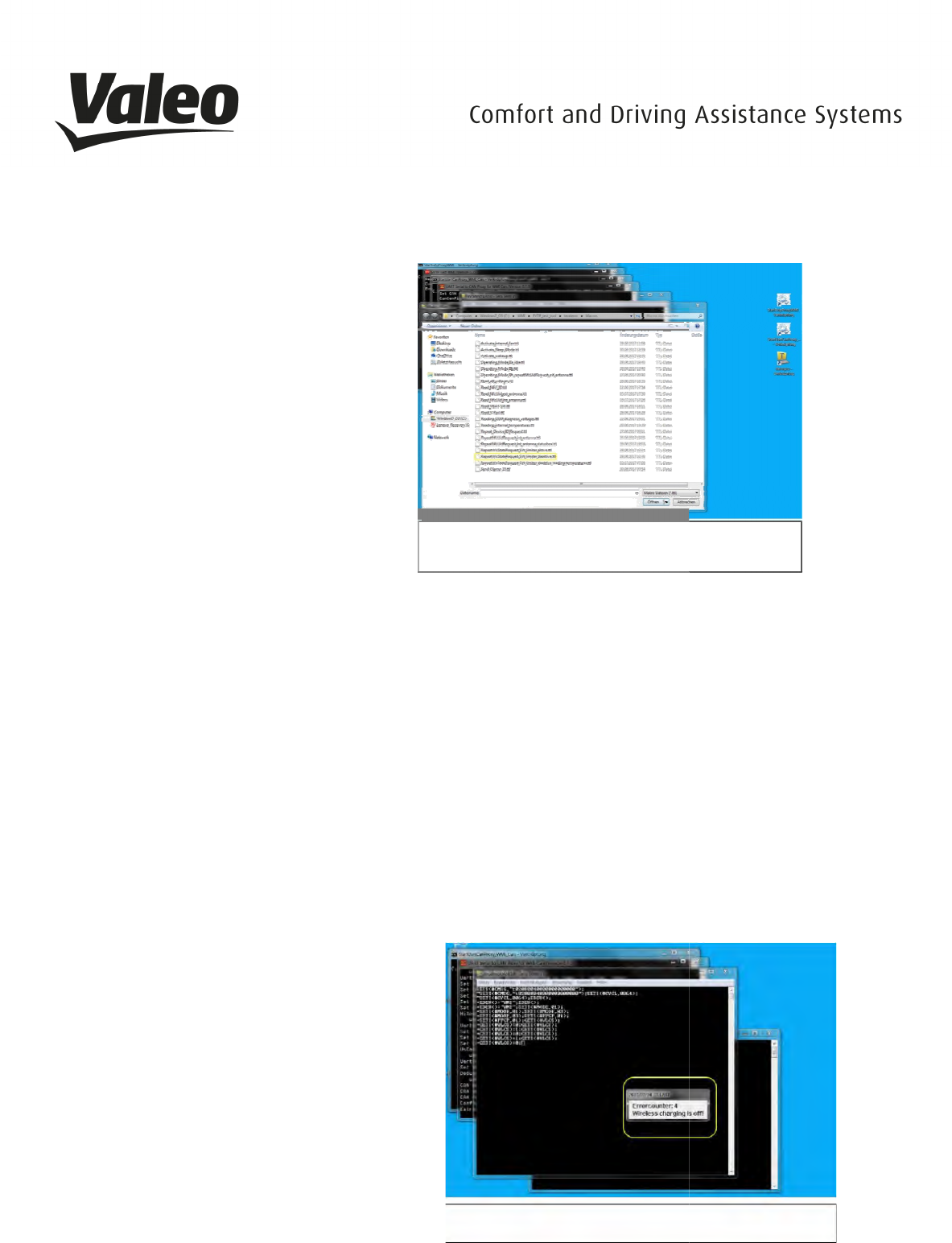
For NFC use the following macros:
Internal:
Read_NFCUid_int_Antenna.ttl
External:
Read_NFCUid_ext_Antenna.ttl
The process for an internal NFC-
antenna is as
1. activate
2. "Send_Clamp_15.ttl"
3.
"Read_NFCUid_int_Antenna.ttl"
4. deactivate
5. "Activate_Sleep_Mode.ttl"
The process for an external NFC-
antenna is as follows:
1. activate
2. "Send_Clamp_15.ttl"
3.
"Read_NFCUid_ext_Antenna.ttl"
4. Deactivate
5. "Activate_Sleep_Mode.ttl"
Attention: You can ignore the error message
“Wireless charging is off! If the error message
"No EVTP response!"appears, it means that
the device is not responding
_____________________________________________________________________________________________________________________________
VALEO – Product Line
Valeo peiker Telematics
For NFC use the following macros:
Read_NFCUid_int_Antenna.ttl
Read_NFCUid_ext_Antenna.ttl
antenna is as
follows:
"Read_NFCUid_int_Antenna.ttl"
antenna is as follows:
"Read_NFCUid_ext_Antenna.ttl"
Attention: You can ignore the error message
“Wireless charging is off! If the error message
"No EVTP response!"appears, it means that
_____________________________________________________________________________________________________________________________
___
Page 16
Valeo peiker Telematics
- www.valeo.de
_____________________________________________________________________________________________________________________________
The process for
wireless charging
1. activate
2. "Send_Clamp_15.ttl"
3. "
RepeatWlcStateRequest_SW_limiter_deaktive.ttl"
4. Now place the
Chargeable Wireless Medium
onto the centre of the Wireless Charger
5.
During charging a light indicates a successful
6. functional capability.
7. This
could take a few moments.
8.
During the test the LED should permanently
glow
9. Deactivate
10. "Activate_Sleep_Mode.ttl"
Note: a rubber mat should be placed between the
wireless charger and the wireless charging receiver
or the NFC-tag
A light indicates a s
uccessful functional capability;
this could take a few moments.
Click on navigation, open the Macro Display,
and click on Finish
Click on navigation and open macro menu.
Click on
Activate_Sleep_Mode.ttl.
now close all Windows and
remove the Wireless Charger
_____________________________________________________________________________________________________________________________
VALEO – Product Line
Valeo peiker Telematics
wireless charging
is as follows:
RepeatWlcStateRequest_SW_limiter_deaktive.ttl"
Chargeable Wireless Medium
onto the centre of the Wireless Charger
During charging a light indicates a successful
could take a few moments.
During the test the LED should permanently
Note: a rubber mat should be placed between the
wireless charger and the wireless charging receiver
uccessful functional capability;
Click on navigation, open the Macro Display,
Click on navigation and open macro menu.
Activate_Sleep_Mode.ttl.
You can
_____________________________________________________________________________________________________________________________
___
Page 17
Valeo peiker Telematics
- www.valeo.de
________________________________________________________________________________________________________________________________
Page 18
VALEO – Product Line Valeo peiker Telematics - www.valeo.de
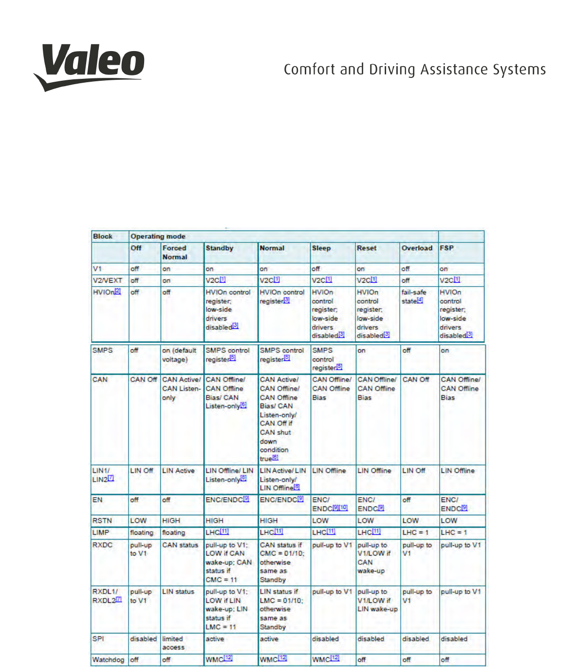
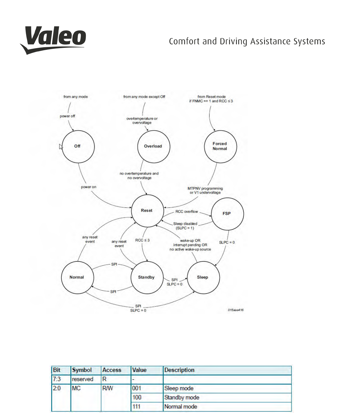
2.8 OPERATING MODES
The system controller of the SBC manages register configuration and controls the internal functions. The system
controller is a state machine. The SBC operating modes and the state transitions are shown in Figure 2.8-1. A
detailed hardware characterization of the SBC operating modes by functional block is listed in the following Table
2.8-1
[1.] Determined by the setting of bits V2C in the regulator control register
[2.] HVIO availability depends on the device variant
[3.] Determined by the settings in the relevant HVIO control register
[4.] See data sheet of the UJA1131HW/3V3, Determined by the settings in the SMPS control register
[5.] Determined by the setting of bits CMC in the CAN control register
[6.] Availability of LIN2 depends on the device variant
[7.] Determined by the setting of bits LMCn in the LIN control register
[8.] Determined by the settings of bits ENC and ENDC in the fail-safe control register
[9.] Since V1 is off, EN can only operate as open-drain output in Sleep mode
[10.] Determined by the setting of bit LHC in the Fail-safe control register
[11.] Determined by the setting of bits WMC in the Watchdog control register
Table 2.8-1: Hardware characterization by functional block
________________________________________________________________________________________________________________________________
Page 19
VALEO – Product Line Valeo peiker Telematics - www.valeo.de
Figure 2.8-1: Operating modes of the System Basis Chip UJA1131HW/3V3
Via SPI2 interface the MWCT1014S is able to sent commands to the SBC so that the SBC can change the
operating mode. The operating mode is selected via bits MC in the Mode Control register, see Table 2.8-2.
SPI address of the Mode Control register: 0x01
Table 2.8-2: Mode Control register
The SBC operating modes are described in the data sheet of the UJA1131HW/3V3,
Fehler! Verweisquelle
konnte nicht gefunden werden.
, section 7.1.1, page 12.
________________________________________________________________________________________________________________________________
Page 20
VALEO – Product Line Valeo peiker Telematics - www.valeo.de
2.9 OPERATIONAL MODES DEVICE DETECTION – QI
After putting the mobile on the WMI surface, the WMI will start up exchanging some CAN commands
from the car .
After initial start the WMI tries to detect via NFC, if an object was placed on the surface
(at this time the process does not send out NFC-Commands)
When the device detection was successful, the system switch to Qi-detection-mode. If the Qi-detection-
mode has found a mobile (acc. Qi-standard) then charging process will start. The WMI was designed
following the Qi standard to charge mobiles prepared for Qi-charging. Because the WMI2 does not fulfill
the whole Qi-standard, therefore no Qi Logo is placed on the WMI and no Qi-certification has been
processed.
If you remove the mobile during charging from the WMI, charging process is stopped immediately.

________________________________________________________________________________________________________________________________
Page 21
VALEO – Product Line Valeo peiker Telematics - www.valeo.de
3. SAFETY RECOMMENDATIONS ACCORDING TO EN62368-1
The WMI2-W167, WMI2-W167-M1, WMI2-W167-M2, WMI2-W167-M3, WMI2-W205, WMI2-W205-M1
devices must be supplied by a limited power source according to EN 62368-1.

________________________________________________________________________________________________________________________________
Page 22
VALEO – Product Line Valeo peiker Telematics - www.valeo.de
4. RED / FCC / IC REGULATORY NOTICES
4.1 MODIFICATIONS
WARNING: peiker acustic GmbH has not approved any changes or modifications to the V1222-0
device by the user. Any changes or modifications could void the user’s authority to operate the
equipment.
AVERTISSEMENT: peiker acustic GmbH n'a approuvé aucun changement ou modification de
l'appareil V1222-0 par l'utilisateur. Tout changement ou modification peut annuler l'autorité de
l'utilisateur à utiliser l'équipement.
4.2 INTERFERENCE
This devices WMI2-W167, WMI2-W167-M1, WMI2-W167-M2, WMI2-W167-M3, WMI2-W205,
WMI2-W205-M1 complies with Part 15 of the FCC Rules and with Industry Canada licence-exempt
RSS standard(s).
Operation is subject to the following two conditions:
(1) this device may not cause harmful interference, and
(2) this device must accept any interference received, including interference that may cause
undesired operation.
Le présent appareil WMI2-W167, WMI2-W167-M1, WMI2-W167-M2, WMI2-W167-M3, WMI2-
W205, WMI2-W205-M1 est conforme aux CNR d'Industrie Canada applicables aux appareils radio
exempts de licence. L'exploitation est autorisée aux deux conditions suivantes:
(1) l'appareil ne doit pas produire de brouillage, et
(2) l'appareil doit accepter tout brouillage radioélectrique subi, même si le brouillage est
susceptible d'en compromettre le fonctionnement.

________________________________________________________________________________________________________________________________
Page 23
VALEO – Product Line Valeo peiker Telematics - www.valeo.de
4.3 FCC CLASS B DIGITAL DEVICE
The WMI2-W167, WMI2-W167-M1, WMI2-W167-M2, WMI2-W167-M3, WMI2-W205, WMI2-
W205-M1 has been tested and found to comply with the limits for a Class B digital device,
pursuant to part 15 of the FCC Rules. These limits are designed to provide reasonable protection
against harmful interference in a residential installation. This equipment generates, uses, and can
radiate radio frequency energy and, if not installed and used in accordance with the instructions,
may cause harmful interference to radio communications. However, there is no guarantee that
interference will not occur in a particular installation. If this equipment does cause harmful
interference to radio or television reception, which can be determined by turning the equipment
off and on, the user is encouraged to try to correct the interference by one or more of the
following measures:
- Reorient or relocate the transmitting antenna.
- Consult the dealer or an experienced radio/TV technician for help.
Les modèles WMI2-W167, WMI2-W167-M1, WMI2-W167-M2, WMI2-W167-M3, WMI2-W205,
WMI2-W205-M1 ont été testés et jugés conformes aux limites d'un appareil numérique de classe
B, conformément à à la partie 15 des règles de la FCC. Ces limites sont conçues pour fournir une
protection raisonnable contre les interférences nuisibles dans une installation résidentielle. Cet
équipement génère, utilise et peut émettre de l'énergie radiofréquence et, s'il n'est pas installé et
utilisé conformément aux instructions, peut causer des interférences nuisibles aux
communications radio. Cependant, il n'y a aucune garantie que des interférences ne se
produiront pas dans une installation particulière. Si cet équipement cause des interférences
nuisibles à la réception radio ou télévision, ce qui peut être déterminé en éteignant et en
rallumant l'équipement, l'utilisateur est encouragé à essayer de corriger l'interférence par une ou
plusieurs des mesures suivantes:
- Réorienter ou déplacer l'antenne d'émission.
- Consulter le revendeur ou un technicien radio / TV expérimenté pour obtenir de l'aide.

________________________________________________________________________________________________________________________________
Page 24
VALEO – Product Line Valeo peiker Telematics - www.valeo.de
4.4 OEM RESPONSIBILTIES
Antenna / Coils
- The systems antenna(s) / coils must be installed such that 5 cm is maintained between
the antenna(s) and the body of the user or nearby persons.
Power Supply
- The power supply of the host device embedding a WMI2-W167, WMI2-W167-M1, WMI2-
W167-M2, WMI2-W167-M3, WMI2-W205, WMI2-W205-M1 must fulfill the following
requirements:
o Nominal supply voltage: 12V
o Operating voltage range: 8V – 16V
o The above operating voltage range MUST never, under any circumstances
(including overshoot voltage and voltage drop), be exceeded.
FCC Labeling
No additional Labeling requirements
IC Labeling
No additional Labeling requirements
4.5 FURTHER NOTES
This device is intended to be used only in vehicles (cars).
This device will be installed in the vehicles in the factory when the vehicle will be manufactured by the
professional workers.
This device is not intended for resale or for 3
rd
parties.