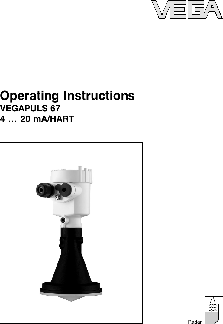
VEGA Americas PULS67 VEGA PULS 67 Level Probing Radar User Manual Manual revised 1

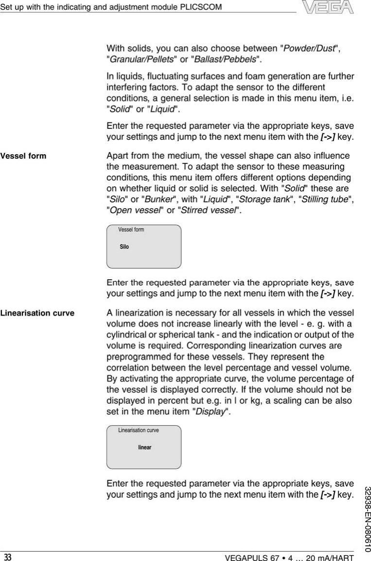
VEGA Americas Inc. VEGA PULS 67 Level Probing Radar Manual revised 1
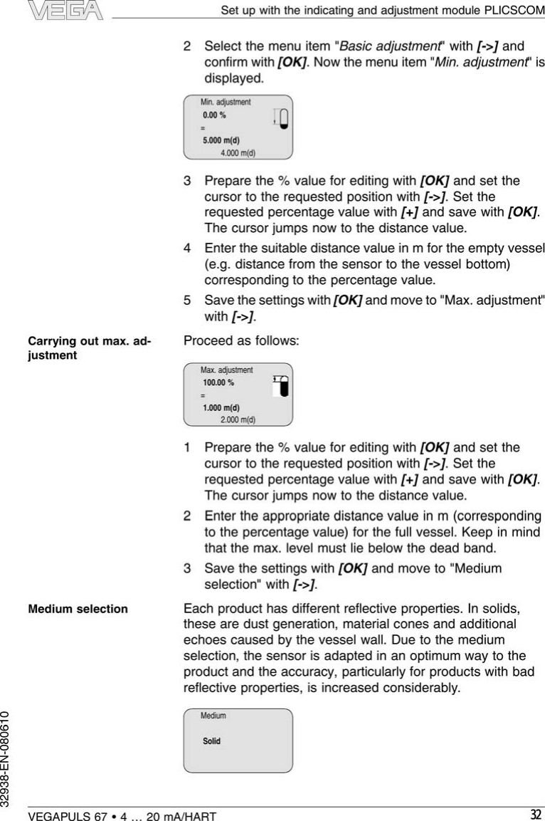
Contents

Manual revised 1

Operating InstructionsVEGAPULS 674…20 mA/HARTRadar
Content1About this document1.1Function . . . . . . . . . . . . . . . . . . . . . . . . . . . . . 41.2Target group . . . . . . . . . . . . . . . . . . . . . . . . . . 41.3Symbolism used . . . . . . . . . . . . . . . . . . . . . . . 42For your safety2.1Authorised personnel. . . . . . . . . . . . . . . . . . . . 52.2Appropriate use. . . . . . . . . . . . . . . . . . . . . . . . 52.3Warning about misuse . . . . . . . . . . . . . . . . . . . 52.4General safety instructions. . . . . . . . . . . . . . . . 52.5Safety approval markings and safety tips . . . . . 62.6CE conformity . . . . . . . . . . . . . . . . . . . . . . . . . 62.7Fulfilling of NAMUR recommendations . . . . . . . 62.8FCC/IC conformity (only for USA/Canada) . . . . . 72.9Safety instructions for Ex areas . . . . . . . . . . . . 82.10 Manufacturer declaration . . . . . . . . . . . . . . . . . 82.11 Functional range of approved instruments . . . . . 92.12 Environmental instructions . . . . . . . . . . . . . . . . 93Product description3.1Configuration. . . . . . . . . . . . . . . . . . . . . . . . . . 103.2Principle of operation. . . . . . . . . . . . . . . . . . . . 113.3Operation . . . . . . . . . . . . . . . . . . . . . . . . . . . . 123.4Packaging,transport and storage . . . . . . . . . . . 124Mounting4.1General instructions. . . . . . . . . . . . . . . . . . . . . 144.2Mounting preparation. . . . . . . . . . . . . . . . . . . . 154.3Mounting instructions. . . . . . . . . . . . . . . . . . . . 185Connecting to power supply5.1Preparing the connection . . . . . . . . . . . . . . . . . 245.2Connection steps -Instrument housing . . . . . . . 255.3Wiring plan,single chamber housing. . . . . . . . . 265.4Wiring plan,double chamber housing . . . . . . . . 285.5Wiring plan -version IP 66/IP 68,1bar. . . . . . . 305.6Switch on phase . . . . . . . . . . . . . . . . . . . . . . . 306Set up with the indicating and adjustment modulePLICSCOM6.1Short description . . . . . . . . . . . . . . . . . . . . . . . 316.2Insert indicating and adjustment module . . . . . . 316.3Adjustment system . . . . . . . . . . . . . . . . . . . . . 332VEGAPULS 67 •4…20 mA/HARTContent32938-EN-080610
6.4Setup procedure . . . . . . . . . . . . . . . . . . . . . . . 346.5Menu schematic . . . . . . . . . . . . . . . . . . . . . . . 416.6Saving the parameter adjustment data . . . . . . . 437Setup with PACTware™and other adjustmentprograms7.1Connect the PC via VEGACONNECT 3. . . . . . 447.2Connect the PC via VEGACONNECT 4. . . . . . 467.3Parameter adjustment with PACTware™. . . . . . 477.4Parameter adjustment with AMS™and PDM . . 487.5Saving the parameter adjustment data . . . . . . . 488Maintenance and fault rectification8.1Maintenance,cleaning . . . . . . . . . . . . . . . . . . . 498.2Remove interferences . . . . . . . . . . . . . . . . . . . 498.3Exchanging the electronics module. . . . . . . . . . 518.4Instrument repair . . . . . . . . . . . . . . . . . . . . . . . 529Dismounting9.1Dismounting steps. . . . . . . . . . . . . . . . . . . . . . 539.2Disposal . . . . . . . . . . . . . . . . . . . . . . . . . . . . . 5310 Supplement10.1Technical data. . . . . . . . . . . . . . . . . . . . . . . . . 5410.2Dimensions . . . . . . . . . . . . . . . . . . . . . . . . . . . 6110.3Industrial property rights. . . . . . . . . . . . . . . . . . 6610.4Trademark . . . . . . . . . . . . . . . . . . . . . . . . . . . 66Supplementary documentationInformation:Supplementary documents appropriate to the ordered versioncome with the delivery.You can find them listed in chapter"Product description".Instructions manuals for accessories and replacementpartsTip:To ensure reliable setup and operation of your VEGAPULS 67,we offer accessories and replacement parts.The associateddocuments are:l27720 -VEGADIS 61l30176 -Electronics module VEGAPULS series 60VEGAPULS 67 •4…20 mA/HART 3Content32938-EN-080610
1About this document1.1FunctionThis operating instructions manual provides all the informationyou need for mounting,connection and setup as well asimportant instructions for maintenance and fault rectification.Please read this information before putting the instrument intooperation and keep this manual accessible in the immediatevicinity of the device.1.2Target groupThis operating instructions manual is directed to trainedpersonnel.The contents of this manual should be madeavailable to these personnel and put into practice by them.1.3Symbolism usedInformation,tip,noteThis symbol indicates helpful additional information.Caution:If this warning is ignored,faults or malfunc-tions can result.Warning:If this warning is ignored,injury to persons and/orserious damage to the instrument can result.Danger:If this warning is ignored,serious injury to personsand/or destruction of the instrument can result.Ex applicationsThis symbol indicates special instructions for Ex applications.lListThe dot set in front indicates a list with no implied sequence.àActionThis arrow indicates a single action.1SequenceNumbers set in front indicate successive steps in a procedure.4VEGAPULS 67 •4…20 mA/HARTAbout this document32938-EN-080610
2For your safety2.1Authorised personnelAll operations described in this operating instructions manualmust be carried out only by trained specialist personnelauthorised by the plant operator.During work on and with the device the required personalprotection equipment must always be worn.2.2Appropriate useVEGAPULS 67 is a sensor for continuous level measurement.You can find detailed information on the application range inchapter "Product description".Operational reliability is ensured only if the instrument isproperly used according to the specifications in the operatinginstructions manual as well as possible supplementaryinstructions.For safety and warranty reasons,any invasive work on thedevice beyond that described in the operating instructionsmanual may be carried out only by personnel authorised by themanufacturer.Arbitrary conversions or modifications areexplicitly forbidden.2.3Warning about misuseInappropriate or incorrect use of the instrument can give rise toapplication-specific hazards,e.g.vessel overfill or damage tosystem components through incorrect mounting or adjustment.2.4General safety instructionsThis is a high-tech instrument requiring the strict observance ofstandard regulations and guidelines.The user must take noteof the safety instructions in this operating instructions manual,the country-specific installation standards as well as allprevailing safety regulations and accident prevention rules.The emitting frequency of VEGAPULS 67 is in the Kbandrange.The low transmitting power lies far below the interna-tionally permitted limit values.When the instrument usedcorrectly,it presents no danger to human health.It may beoperated without restriction outside of closed metallic vessels.VEGAPULS 67 •4…20 mA/HART 5For your safety32938-EN-080610
The instrument must only be operated in a technically flawlessand reliable condition.The operator is responsible for trouble-free operation of the instrument.During the entire duration of use,the user is obliged todetermine the compliance of the required occupational safetymeasures with the current valid rules and regulations and alsotake note of new regulations.2.5Safety approval markings and safety tipsThe safety approval markings and safety tips on the devicemust be observed.2.6CE conformityVEGAPULS 67 is in CE conformity with EMC (89/336/EWG)and LVD (73/23/EWG).Conformity has been judged according to the followingstandards:lEMC:-Emission EN 61326:1997 (class B)-Susceptibility EN 61326:1997/A1:1998lR&TTE directive:I-ETS 300-440 Expert Opinion No.05-111723,Notified Body No.0700lLVD:EN 61010-1:20012.7Fulfilling of NAMUR recommendationsWith respect to interference resistance and emitted interfer-ence,the NAMUR recommendation NE 21 is fulfilled.With respect to compatibility,the NAMUR recommendationNE 53 is fulfilled.This applies also to the correspondingindicating and adjustment components.VEGA instruments aregenerally upward and downward compatible.lSensor software for DTM VEGAPULS 67 HART,PA or FFlDTM VEGAPULS 67 for adjustment software PACTware™lIndicating and adjustment module for sensor softwareThe parameter adjustment of the basic sensor functions isindependent of the software version.The range of availablefunctions depends on the respective software version of theindividual components.The software version of VEGAPULS 67 can be determined asfollows:6VEGAPULS 67 •4…20 mA/HARTFor your safety32938-EN-080610
lvia PACTware™lon the type label of the electronicslvia the indicating and adjustment moduleYou can view all software histories on our website www.vega.com.Make use of this advantage and get registered for updateinformation via e-mail.2.8FCC/IC conformity (only for USA/Canada)The VEGAPULS 67 is limited to use in enclosed metal,concrete,or fibre-reinforced plastic vessels.Note about this manual:this manual is intended to be usedinternationally.There are figures and illustrations which depictthe use of the device in open air and open-topped tankenvironments.These types of installations are not in com-pliance with FCC/IC approvals.This VEGAPULS 67 sensor is FCC/IC approved with all of theantennas described in this operating instructions manual.Modifications or changes to this device not expresslyapproved by VEGA could void the user's authority to operatethis equipment.This device complies with Part 15 of the FCC Rules.Operationis subject to the following two conditions:lThe device may not cause harmful interference,andlThis device must accept any interference received,including interference that may cause undesired operation.This equipment has been tested and found to comply with thelimits for a Class Adigital device,pursuant to Part 15 of theFCC Rules.These limits are designed to provide reasonableprotection against harmful interference when the equipment isoperated in a commercial environment.This equipmentgenerates,uses,and can radiate radio frequency energy and,if not installed and used in accordance with the instructionmanual,may cause harmful interference to radio communica-tions.Operation of this equipment in a residential area is likelyto cause harmful interference in which case the users will berequired to correct the inference at their own expense.VEGAPULS 67 •4…20 mA/HART 7For your safety32938-EN-080610The VEGAPULS 67 must be congured pointing downward inside enclosed metal, concrete, or bre-reinforced plastic vessels only.  Any other use is prohibited.
2.9Safety instructions for Ex areasPlease note the Ex-specific safety information for installationand operation in Ex areas.These safety instructions are part ofthe operating instructions manual and come with the Ex-approved instruments.2.10 Manufacturer declarationIn conformity with DIN EN 60079-14/2004,para.5.2.3,pointc1,VEGAPULS 67 is suitable for use in zone 2.The operator must use the instrument as it was intended to beused and follow the specifications of the following documents:lthis operating instructions manuallthis manufacturer declaration (24626)lthe applicable installation regulationsMax.increase of the surface temperature during operation:27 K(individual components in the instrument)With an ambient temperature of 70 °C(158 °F)on the housingand a process temperature of 70 °C(158 °F), the max.ambienttemperature during operation is 97 °C(207 °F).Measures to maintain explosion protection during operation:lOperate the instrument in the range of the specifiedelectrical limit values.Permissible supply voltage:see"Technical data"lMount and operate the instrument in such a way that nodanger of ignition from electrostatic charges is to beexpected.The antenna,the process fitting or the housing(as the case may be depending on instrument version)aremade of electrically non-conductive plastic.lMake sure that the seal is mounted correctly betweenlower part of the housing and cover.Screw the cover ontightly.lMake sure there is no explosive atmosphere present if youintend to operate the instrument with opened coverlMake sure that the cable gland is tight and strain-relieved.The outer diameter of the connection cable must beadapted to the cable gland.Tighten the pressure screw ofthe cable gland carefully.lCover unused openings for cable glands tightlylMount the instrument in such a way that the sensor cannottouch the vessel wall or vessel installations.Keep in mindthe influence of product movement in the vessel.8VEGAPULS 67 •4…20 mA/HARTFor your safety32938-EN-080610
lThe surface temperature of the housing must not exceedthe ignition temperature of the surrounding explosiveatmosphereThis instrument was assessed by a person who fulfils the DINEN 60079-14 requirements.2.11 Functional range of approved instrumentsInstruments with specific approvals are partly supplied with anearlier hardware or software version.For approval-technicalreasons,some functions for these instruments will be availableonly at a later date.You will find corresponding instructions in the description ofthe individual functions in this operating instructions manual.2.12 Environmental instructionsProtection of the environment is one of our most importantduties.That is why we have introduced an environmentmanagement system with the goal of continuously improvingcompany environmental protection.The environment man-agement system is certified according to DIN EN ISO 14001.Please help us fulfil this obligation by observing the environ-mental instructions in this manual:lChapter "Packaging,transport and storage"lChapter "Disposal"VEGAPULS 67 •4…20 mA/HART 9For your safety32938-EN-080610
3Product description3.1ConfigurationThe scope of delivery encompasses:lVEGAPULS 67 radar sensorlMounting strap (option)lCompression or adapter flange (optional)lDocumentation-this operating instructions manual-Operating instructions manual -27835 "Indicating andadjustment module PLICSCOM"(optional)-Supplementary instructions manual -31708 "Heatingfor indicating and adjustment module"(optional)-Supplementary instructions manual "Plug connector forcontinuously measuring sensors"(optional)-Ex-specific"Safety instructions"(with Ex-versions)-if necessary,further certificatesVEGAPULS 67 consists of the following components:lProcess fitting with encapsulated antenna systemlHousing with electronics,optionally available with plugconnector,optionally available with connection cablelHousing cover,optionally available with indicating andadjustment module PLICSCOMThe components are available in different versions.Scope of deliveryComponents10 VEGAPULS 67 •4…20 mA/HARTProduct description32938-EN-080610
3 42 1 Fig.1:VEGAPULS 67 -version with plastic housing1Housing cover with integrated PLICSCOM (optional)2Housing with electronics3Process fitting with plastic horn antenna4Antenna cover3.2Principle of operationVEGAPULS 67 is a radar sensor in K-band technology forcontinuous level measurement in solids.The antenna of the radar sensor emits short radar pulses witha duration of approx.1ns.These pulses are reflected by theproduct and received by the antenna as echoes.The runningtime of the radar pulses from emission to reception isproportional to the distance and hence to the level.Thedetermined level is converted into an appropriate output signaland outputted as measured value.Two-wire electronics 4…20 mA/HART for power supply andmeasured value transmission over the same cable.The supply voltage range can differ depending on theinstrument version.Data for power supply are specified in chapter "Technicaldata".The backlight of the indicating and adjustment module ispowered by the sensor.The prerequisite for this is a supplyvoltage at a certain level.The exact voltage specifications arestated in chapter "Technical data".Application rangeFunctional principleVoltage supplyVEGAPULS 67 •4…20 mA/HART 11Product description32938-EN-080610
The optional heating requires its own power supply.You canfind detailed information in the supplementary instructionsmanual "Heating for indicating and adjustment module".Thisfunction is generally not available for approved instruments.3.3OperationVEGAPULS 67 can be adjusted with different adjustmentmedia:lwith indicating and adjustment modulelwith the suitable VEGA DTM in conjunction with anadjustment software according to the FDT/DTM standard,e.g.PACTware™and PClwith manufacturer-specific adjustment programs AMS™orPDMlWith a HART handheldThe entered parameters are generally saved in VEGAPULS67,optionally also in the indicating and adjustment module orin PACTware™.3.4Packaging,transport and storageYour instrument was protected by packaging during transport.Its capacity to handle normal loads during transport is assuredby a test according to DIN EN 24180.The packaging of standard instruments consists of environ-ment-friendly,recyclable cardboard.For special versions,PEfoam or PE foil is also used.Dispose of the packaging materialvia specialised recycling companies.Transport must be carried out under consideration of the noteson the transport packaging.Nonobservance of these instruc-tions can cause damage to the device.The delivery must be checked for completeness and possibletransit damage immediately at receipt.Ascertained transitdamage or concealed defects must be appropriately dealtwith.Up to the time of installation,the packages must be left closedand stored according to the orientation and storage markingson the outside.Unless otherwise indicated,the packages must be stored onlyunder the following conditions:PackagingTransportTransport inspectionStorage12 VEGAPULS 67 •4…20 mA/HARTProduct description32938-EN-080610
lNot in the openlDry and dust freelNot exposed to corrosive medialProtected against solar radiationlAvoiding mechanical shock and vibrationlStorage and transport temperature see "Supplement -Technical data -Ambient conditions"lRelative humidity 20 …85 %Storage and transporttemperatureVEGAPULS 67 •4…20 mA/HART 13Product description32938-EN-080610
4Mounting4.1General instructionsSelect an installation position you can easily reach formounting and connecting as well as later retrofitting of anindicating and adjustment module.The housing can be rotatedby 330°without the use of any tools.You can also install theindicating and adjustment module in four different positions(each displaced by 90°).Use the recommended cables (see chapter "Connecting topower supply")and tighten the cable gland.You can give your instrument additional protection againstmoisture penetration by leading the connection cable down-ward in front of the cable entry.Rain and condensation watercan thus drain off.This applies mainly to outdoor mounting aswell as installation in areas where high humidity is expected (e.g.through cleaning processes)or on cooled or heatedvessels.Fig.2:Measures against moisture penetrationThe reference plane for the measuring range of the sensors isthe contact surface on the side of the antenna cover.Mounting positionMoistureMeasuring range14 VEGAPULS 67 •4…20 mA/HARTMounting32938-EN-0806104Mounting4.1General instructionsSelect an installation position you can easily reach formounting and connecting as well as later retrofitting of anindicating and adjustment module.The housing can be rotatedby 330°without the use of any tools.You can also install theindicating and adjustment module in four different positions(each displaced by 90°).Use the recommended cables (see chapter "Connecting topower supply")and tighten the cable gland.You can give your instrument additional protection againstmoisture penetration by leading the connection cable down-ward in front of the cable entry.Rain and condensation watercan thus drain off.This applies mainly to outdoor mounting aswell as installation in areas where high humidity is expected (e.g.through cleaning processes)or on cooled or heatedvessels.Fig.2:Measures against moisture penetrationThe reference plane for the measuring range of the sensors isthe contact surface on the side of the antenna cover.Mounting positionMoistureMeasuring range14 VEGAPULS 67 •4…20 mA/HARTMounting32938-EN-080610The VEGAPULS 67 must be mounted such that it is pointing downward inside enclosed metal, concrete, or bre-reinforced plastic vessels only.  Any other use is prohibited. Select an installation position you can easily reach for mounting and connecting as well as later retrotting of an indicating and adjustment module. The housing can be rotated by 330° without the use of any tools. You can also install the indicating and adjustment module in four different positions (each displaced by 90°).
-

Navigation menu