VEGA Americas PULS67 VEGA PULS 67 Level Probing Radar User Manual Manual revised 1
VEGA Americas Inc. VEGA PULS 67 Level Probing Radar Manual revised 1
Contents
- 1. Manual revised 1
- 2. Manual revised 2
Manual revised 1
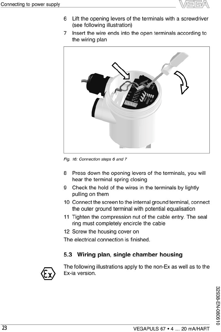
Operating Instructions
VEGAPULS 67
4…20 mA/HART
Radar

Content
1About this document
1.1Function . . . . . . . . . . . . . . . . . . . . . . . . . . . . . 4
1.2Target group . . . . . . . . . . . . . . . . . . . . . . . . . . 4
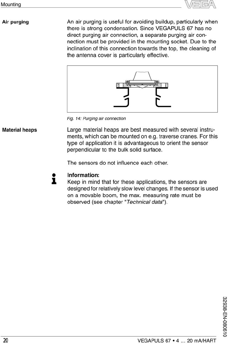
1.3Symbolism used . . . . . . . . . . . . . . . . . . . . . . . 4
2For your safety
2.1Authorised personnel. . . . . . . . . . . . . . . . . . . . 5
2.2Appropriate use. . . . . . . . . . . . . . . . . . . . . . . . 5
2.3Warning about misuse . . . . . . . . . . . . . . . . . . . 5
2.4General safety instructions. . . . . . . . . . . . . . . . 5
2.5Safety approval markings and safety tips . . . . . 6
2.6CE conformity . . . . . . . . . . . . . . . . . . . . . . . . . 6
2.7Fulfilling of NAMUR recommendations . . . . . . . 6
2.8FCC/IC conformity (only for USA/Canada) . . . . . 7
2.9Safety instructions for Ex areas . . . . . . . . . . . . 8
2.10 Manufacturer declaration . . . . . . . . . . . . . . . . . 8
2.11 Functional range of approved instruments . . . . . 9
2.12 Environmental instructions . . . . . . . . . . . . . . . . 9
3Product description
3.1Configuration. . . . . . . . . . . . . . . . . . . . . . . . . . 10
3.2Principle of operation. . . . . . . . . . . . . . . . . . . . 11
3.3Operation . . . . . . . . . . . . . . . . . . . . . . . . . . . . 12
3.4Packaging,transport and storage . . . . . . . . . . . 12
4Mounting
4.1General instructions. . . . . . . . . . . . . . . . . . . . . 14
4.2Mounting preparation. . . . . . . . . . . . . . . . . . . . 15
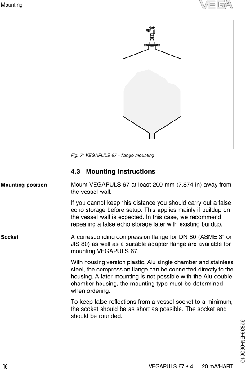
4.3Mounting instructions. . . . . . . . . . . . . . . . . . . . 18
5Connecting to power supply
5.1Preparing the connection . . . . . . . . . . . . . . . . . 24
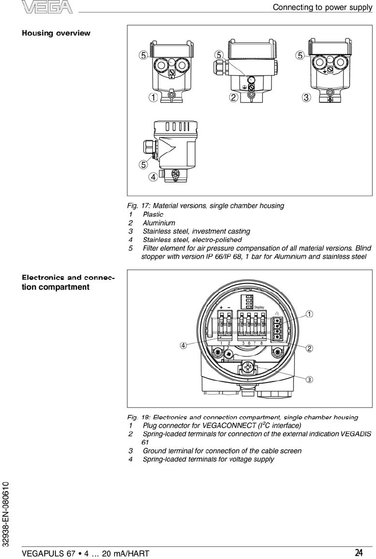
5.2Connection steps -Instrument housing . . . . . . . 25
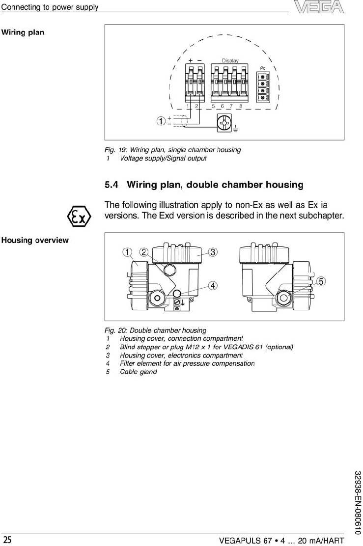
5.3Wiring plan,single chamber housing. . . . . . . . . 26
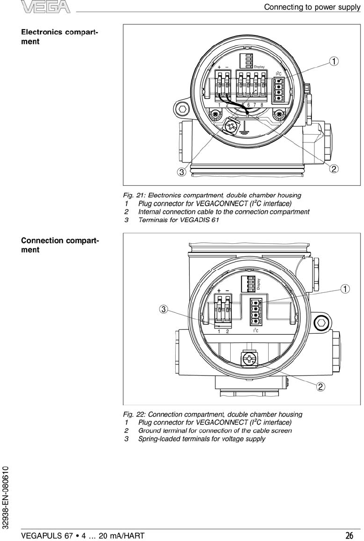
5.4Wiring plan,double chamber housing . . . . . . . . 28
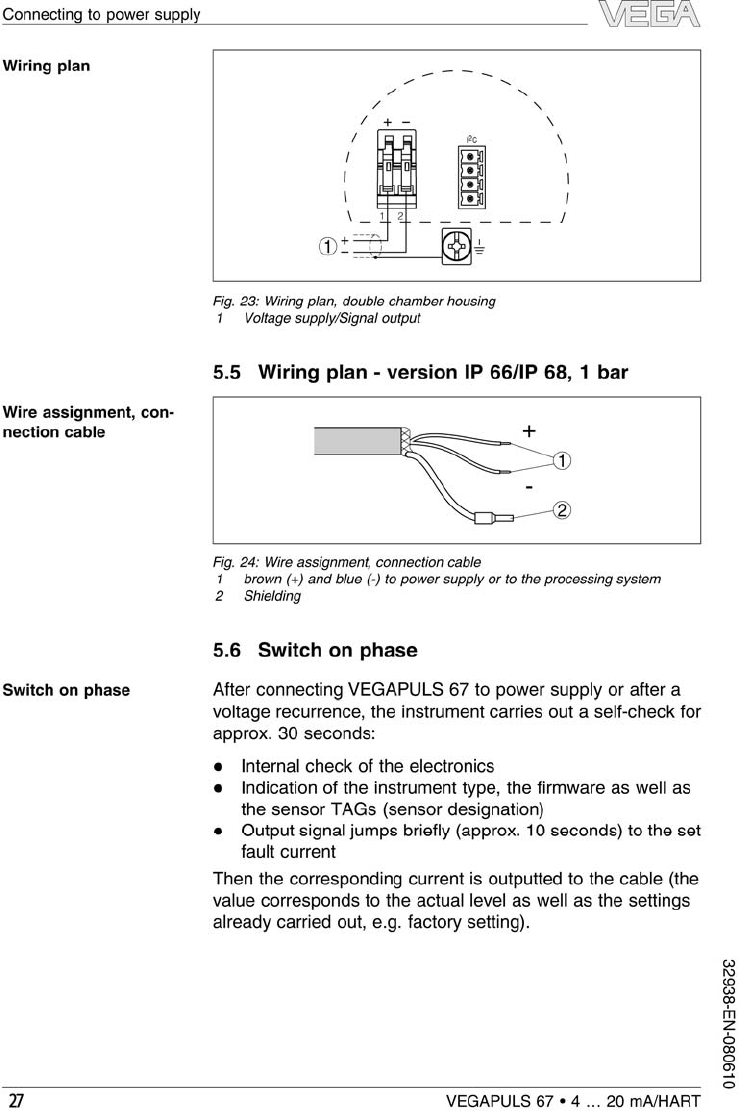
5.5Wiring plan -version IP 66/IP 68,1bar. . . . . . . 30
5.6Switch on phase . . . . . . . . . . . . . . . . . . . . . . . 30
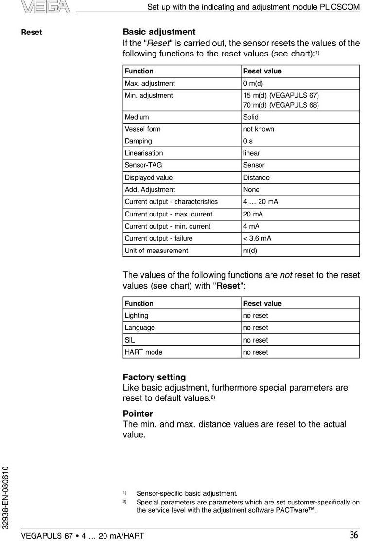
6Set up with the indicating and adjustment module
PLICSCOM
6.1Short description . . . . . . . . . . . . . . . . . . . . . . . 31
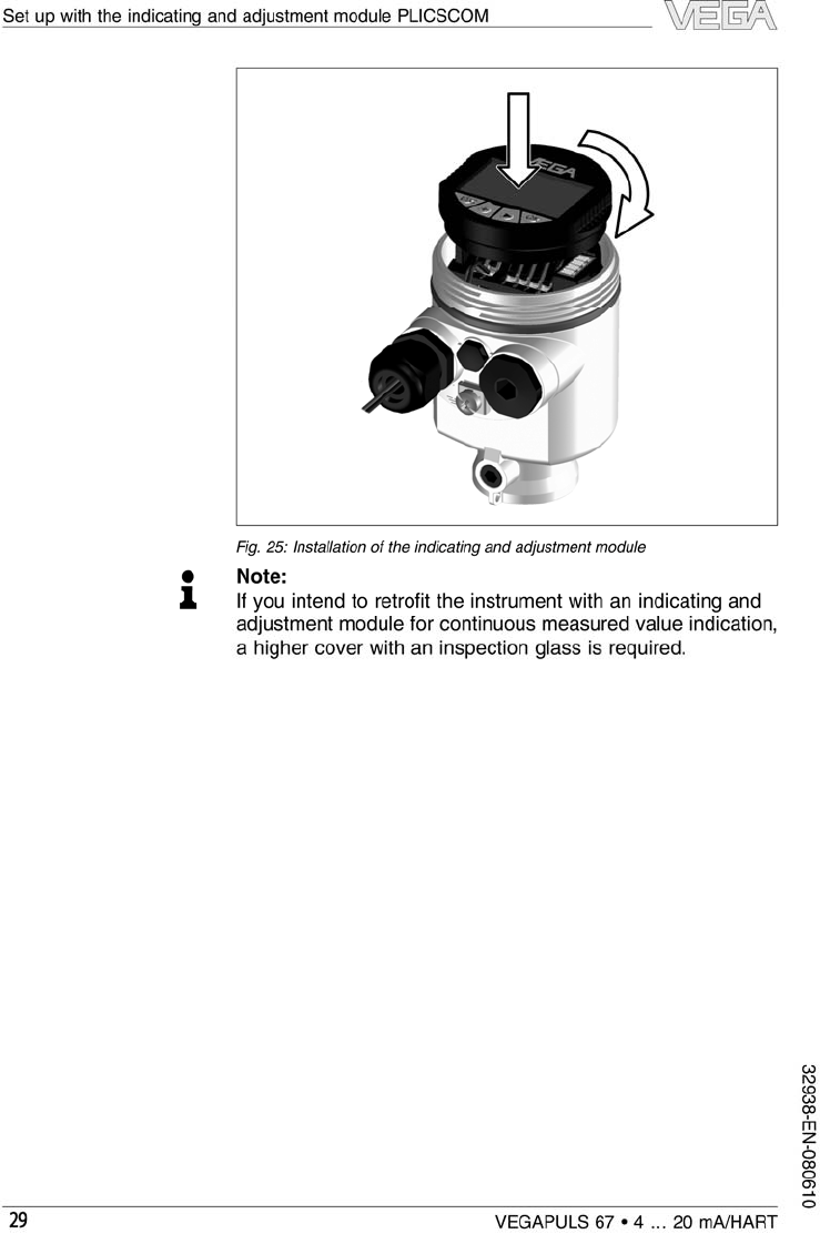
6.2Insert indicating and adjustment module . . . . . . 31
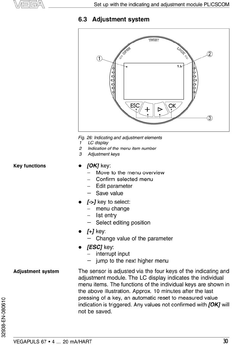
6.3Adjustment system . . . . . . . . . . . . . . . . . . . . . 33
2VEGAPULS 67 •4…20 mA/HART
Content
32938-EN-080610

6.4Setup procedure . . . . . . . . . . . . . . . . . . . . . . . 34
6.5Menu schematic . . . . . . . . . . . . . . . . . . . . . . . 41
6.6Saving the parameter adjustment data . . . . . . . 43
7Setup with PACTware™and other adjustment
programs
7.1Connect the PC via VEGACONNECT 3. . . . . . 44
7.2Connect the PC via VEGACONNECT 4. . . . . . 46
7.3Parameter adjustment with PACTware™. . . . . . 47
7.4Parameter adjustment with AMS™and PDM . . 48
7.5Saving the parameter adjustment data . . . . . . . 48
8Maintenance and fault rectification
8.1Maintenance,cleaning . . . . . . . . . . . . . . . . . . . 49
8.2Remove interferences . . . . . . . . . . . . . . . . . . . 49
8.3Exchanging the electronics module. . . . . . . . . . 51
8.4Instrument repair . . . . . . . . . . . . . . . . . . . . . . . 52
9Dismounting
9.1Dismounting steps. . . . . . . . . . . . . . . . . . . . . . 53
9.2Disposal . . . . . . . . . . . . . . . . . . . . . . . . . . . . . 53
10 Supplement
10.1Technical data. . . . . . . . . . . . . . . . . . . . . . . . . 54
10.2Dimensions . . . . . . . . . . . . . . . . . . . . . . . . . . . 61
10.3Industrial property rights. . . . . . . . . . . . . . . . . . 66
10.4Trademark . . . . . . . . . . . . . . . . . . . . . . . . . . . 66
Supplementary documentation
Information:
Supplementary documents appropriate to the ordered version
come with the delivery.You can find them listed in chapter
"Product description".
Instructions manuals for accessories and replacement
parts
Tip:
To ensure reliable setup and operation of your VEGAPULS 67,
we offer accessories and replacement parts.The associated
documents are:
l27720 -VEGADIS 61
l30176 -Electronics module VEGAPULS series 60
VEGAPULS 67 •4…20 mA/HART 3
Content
32938-EN-080610
1About this document
1.1Function
This operating instructions manual provides all the information
you need for mounting,connection and setup as well as
important instructions for maintenance and fault rectification.
Please read this information before putting the instrument into
operation and keep this manual accessible in the immediate
vicinity of the device.
1.2Target group
This operating instructions manual is directed to trained
personnel.The contents of this manual should be made
available to these personnel and put into practice by them.
1.3Symbolism used
Information,tip,note
This symbol indicates helpful additional information.
Caution:If this warning is ignored,faults or malfunc-
tions can result.
Warning:If this warning is ignored,injury to persons and/or
serious damage to the instrument can result.
Danger:If this warning is ignored,serious injury to persons
and/or destruction of the instrument can result.
Ex applications
This symbol indicates special instructions for Ex applications.
lList
The dot set in front indicates a list with no implied sequence.
àAction
This arrow indicates a single action.
1Sequence
Numbers set in front indicate successive steps in a procedure.
4VEGAPULS 67 •4…20 mA/HART
About this document
32938-EN-080610

2For your safety
2.1Authorised personnel
All operations described in this operating instructions manual
must be carried out only by trained specialist personnel
authorised by the plant operator.
During work on and with the device the required personal
protection equipment must always be worn.
2.2Appropriate use
VEGAPULS 67 is a sensor for continuous level measurement.
You can find detailed information on the application range in
chapter "Product description".
Operational reliability is ensured only if the instrument is
properly used according to the specifications in the operating
instructions manual as well as possible supplementary
instructions.
For safety and warranty reasons,any invasive work on the
device beyond that described in the operating instructions
manual may be carried out only by personnel authorised by the
manufacturer.Arbitrary conversions or modifications are
explicitly forbidden.
2.3Warning about misuse
Inappropriate or incorrect use of the instrument can give rise to
application-specific hazards,e.g.vessel overfill or damage to
system components through incorrect mounting or adjustment.
2.4General safety instructions
This is a high-tech instrument requiring the strict observance of
standard regulations and guidelines.The user must take note
of the safety instructions in this operating instructions manual,
the country-specific installation standards as well as all
prevailing safety regulations and accident prevention rules.
The emitting frequency of VEGAPULS 67 is in the Kband
range.The low transmitting power lies far below the interna-
tionally permitted limit values.When the instrument used
correctly,it presents no danger to human health.It may be
operated without restriction outside of closed metallic vessels.
VEGAPULS 67 •4…20 mA/HART 5
For your safety
32938-EN-080610

The instrument must only be operated in a technically flawless
and reliable condition.The operator is responsible for trouble-
free operation of the instrument.
During the entire duration of use,the user is obliged to
determine the compliance of the required occupational safety
measures with the current valid rules and regulations and also
take note of new regulations.
2.5Safety approval markings and safety tips
The safety approval markings and safety tips on the device
must be observed.
2.6CE conformity
VEGAPULS 67 is in CE conformity with EMC (89/336/EWG)
and LVD (73/23/EWG).
Conformity has been judged according to the following
standards:
lEMC:
-Emission EN 61326:1997 (class B)
-Susceptibility EN 61326:1997/A1:1998
lR&TTE directive:I-ETS 300-440 Expert Opinion No.
05-111723,Notified Body No.0700
lLVD:EN 61010-1:2001
2.7Fulfilling of NAMUR recommendations
With respect to interference resistance and emitted interfer-
ence,the NAMUR recommendation NE 21 is fulfilled.
With respect to compatibility,the NAMUR recommendation
NE 53 is fulfilled.This applies also to the corresponding
indicating and adjustment components.VEGA instruments are
generally upward and downward compatible.
lSensor software for DTM VEGAPULS 67 HART,PA or FF
lDTM VEGAPULS 67 for adjustment software PACTware™
lIndicating and adjustment module for sensor software
The parameter adjustment of the basic sensor functions is
independent of the software version.The range of available
functions depends on the respective software version of the
individual components.
The software version of VEGAPULS 67 can be determined as
follows:
6VEGAPULS 67 •4…20 mA/HART
For your safety
32938-EN-080610

lvia PACTware™
lon the type label of the electronics
lvia the indicating and adjustment module
You can view all software histories on our website www.vega.
com.Make use of this advantage and get registered for update
information via e-mail.
2.8FCC/IC conformity (only for USA/Canada)
The VEGAPULS 67 is limited to use in enclosed metal,
concrete,or fibre-reinforced plastic vessels.
Note about this manual:this manual is intended to be used
internationally.There are figures and illustrations which depict
the use of the device in open air and open-topped tank
environments.These types of installations are not in com-
pliance with FCC/IC approvals.
This VEGAPULS 67 sensor is FCC/IC approved with all of the
antennas described in this operating instructions manual.
Modifications or changes to this device not expressly
approved by VEGA could void the user's authority to operate
this equipment.
This device complies with Part 15 of the FCC Rules.Operation
is subject to the following two conditions:
lThe device may not cause harmful interference,and
lThis device must accept any interference received,
including interference that may cause undesired operation.
This equipment has been tested and found to comply with the
limits for a Class Adigital device,pursuant to Part 15 of the
FCC Rules.These limits are designed to provide reasonable
protection against harmful interference when the equipment is
operated in a commercial environment.This equipment
generates,uses,and can radiate radio frequency energy and,
if not installed and used in accordance with the instruction
manual,may cause harmful interference to radio communica-
tions.Operation of this equipment in a residential area is likely
to cause harmful interference in which case the users will be
required to correct the inference at their own expense.
VEGAPULS 67 •4…20 mA/HART 7
For your safety
32938-EN-080610
The VEGAPULS 67 must be congured pointing downward
inside enclosed metal, concrete, or bre-reinforced plastic
vessels only. Any other use is prohibited.

2.9Safety instructions for Ex areas
Please note the Ex-specific safety information for installation
and operation in Ex areas.These safety instructions are part of
the operating instructions manual and come with the Ex-
approved instruments.
2.10 Manufacturer declaration
In conformity with DIN EN 60079-14/2004,para.5.2.3,point
c1,VEGAPULS 67 is suitable for use in zone 2.
The operator must use the instrument as it was intended to be
used and follow the specifications of the following documents:
lthis operating instructions manual
lthis manufacturer declaration (24626)
lthe applicable installation regulations
Max.increase of the surface temperature during operation:
27 K(individual components in the instrument)
With an ambient temperature of 70 °C(158 °F)on the housing
and a process temperature of 70 °C(158 °F), the max.ambient
temperature during operation is 97 °C(207 °F).
Measures to maintain explosion protection during operation:
lOperate the instrument in the range of the specified
electrical limit values.Permissible supply voltage:see
"Technical data"
lMount and operate the instrument in such a way that no
danger of ignition from electrostatic charges is to be
expected.The antenna,the process fitting or the housing
(as the case may be depending on instrument version)are
made of electrically non-conductive plastic.
lMake sure that the seal is mounted correctly between
lower part of the housing and cover.Screw the cover on
tightly.
lMake sure there is no explosive atmosphere present if you
intend to operate the instrument with opened cover
lMake sure that the cable gland is tight and strain-relieved.
The outer diameter of the connection cable must be
adapted to the cable gland.Tighten the pressure screw of
the cable gland carefully.
lCover unused openings for cable glands tightly
lMount the instrument in such a way that the sensor cannot
touch the vessel wall or vessel installations.Keep in mind
the influence of product movement in the vessel.
8VEGAPULS 67 •4…20 mA/HART
For your safety
32938-EN-080610

lThe surface temperature of the housing must not exceed
the ignition temperature of the surrounding explosive
atmosphere
This instrument was assessed by a person who fulfils the DIN
EN 60079-14 requirements.
2.11 Functional range of approved instruments
Instruments with specific approvals are partly supplied with an
earlier hardware or software version.For approval-technical
reasons,some functions for these instruments will be available
only at a later date.
You will find corresponding instructions in the description of
the individual functions in this operating instructions manual.
2.12 Environmental instructions
Protection of the environment is one of our most important
duties.That is why we have introduced an environment
management system with the goal of continuously improving
company environmental protection.The environment man-
agement system is certified according to DIN EN ISO 14001.
Please help us fulfil this obligation by observing the environ-
mental instructions in this manual:
lChapter "Packaging,transport and storage"
lChapter "Disposal"
VEGAPULS 67 •4…20 mA/HART 9
For your safety
32938-EN-080610

3Product description
3.1Configuration
The scope of delivery encompasses:
lVEGAPULS 67 radar sensor
lMounting strap (option)
lCompression or adapter flange (optional)
lDocumentation
-this operating instructions manual
-Operating instructions manual -27835 "Indicating and
adjustment module PLICSCOM"(optional)
-Supplementary instructions manual -31708 "Heating
for indicating and adjustment module"(optional)
-Supplementary instructions manual "Plug connector for
continuously measuring sensors"(optional)
-Ex-specific"Safety instructions"(with Ex-versions)
-if necessary,further certificates
VEGAPULS 67 consists of the following components:
lProcess fitting with encapsulated antenna system
lHousing with electronics,optionally available with plug
connector,optionally available with connection cable
lHousing cover,optionally available with indicating and
adjustment module PLICSCOM
The components are available in different versions.
Scope of delivery
Components
10 VEGAPULS 67 •4…20 mA/HART
Product description
32938-EN-080610
3
4
2
1
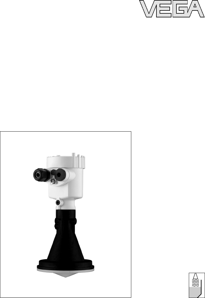
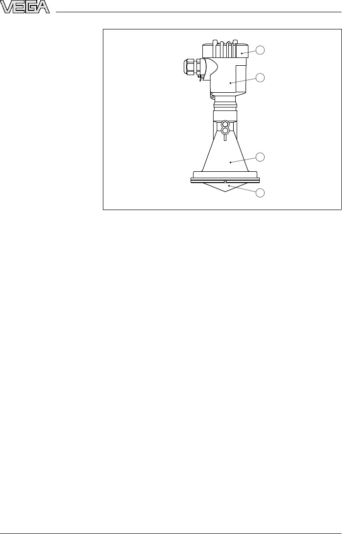
Fig.1:VEGAPULS 67 -version with plastic housing
1Housing cover with integrated PLICSCOM (optional)
2Housing with electronics
3Process fitting with plastic horn antenna
4Antenna cover
3.2Principle of operation
VEGAPULS 67 is a radar sensor in K-band technology for
continuous level measurement in solids.
The antenna of the radar sensor emits short radar pulses with
a duration of approx.1ns.These pulses are reflected by the
product and received by the antenna as echoes.The running
time of the radar pulses from emission to reception is
proportional to the distance and hence to the level.The
determined level is converted into an appropriate output signal
and outputted as measured value.
Two-wire electronics 4…20 mA/HART for power supply and
measured value transmission over the same cable.
The supply voltage range can differ depending on the
instrument version.
Data for power supply are specified in chapter "Technical
data".
The backlight of the indicating and adjustment module is
powered by the sensor.The prerequisite for this is a supply
voltage at a certain level.The exact voltage specifications are
stated in chapter "Technical data".
Application range
Functional principle
Voltage supply
VEGAPULS 67 •4…20 mA/HART 11
Product description
32938-EN-080610

The optional heating requires its own power supply.You can
find detailed information in the supplementary instructions
manual "Heating for indicating and adjustment module".This
function is generally not available for approved instruments.
3.3Operation
VEGAPULS 67 can be adjusted with different adjustment
media:
lwith indicating and adjustment module
lwith the suitable VEGA DTM in conjunction with an
adjustment software according to the FDT/DTM standard,
e.g.PACTware™and PC
lwith manufacturer-specific adjustment programs AMS™or
PDM
lWith a HART handheld
The entered parameters are generally saved in VEGAPULS
67,optionally also in the indicating and adjustment module or
in PACTware™.
3.4Packaging,transport and storage
Your instrument was protected by packaging during transport.
Its capacity to handle normal loads during transport is assured
by a test according to DIN EN 24180.
The packaging of standard instruments consists of environ-
ment-friendly,recyclable cardboard.For special versions,PE
foam or PE foil is also used.Dispose of the packaging material
via specialised recycling companies.
Transport must be carried out under consideration of the notes
on the transport packaging.Nonobservance of these instruc-
tions can cause damage to the device.
The delivery must be checked for completeness and possible
transit damage immediately at receipt.Ascertained transit
damage or concealed defects must be appropriately dealt
with.
Up to the time of installation,the packages must be left closed
and stored according to the orientation and storage markings
on the outside.
Unless otherwise indicated,the packages must be stored only
under the following conditions:
Packaging
Transport
Transport inspection
Storage
12 VEGAPULS 67 •4…20 mA/HART
Product description
32938-EN-080610

lNot in the open
lDry and dust free
lNot exposed to corrosive media
lProtected against solar radiation
lAvoiding mechanical shock and vibration
lStorage and transport temperature see "Supplement -
Technical data -Ambient conditions"
lRelative humidity 20 …85 %
Storage and transport
temperature
VEGAPULS 67 •4…20 mA/HART 13
Product description
32938-EN-080610
4Mounting
4.1General instructions
Select an installation position you can easily reach for
mounting and connecting as well as later retrofitting of an
indicating and adjustment module.The housing can be rotated
by 330°without the use of any tools.You can also install the
indicating and adjustment module in four different positions
(each displaced by 90°).
Use the recommended cables (see chapter "Connecting to
power supply")and tighten the cable gland.
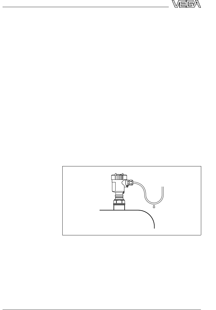
You can give your instrument additional protection against
moisture penetration by leading the connection cable down-
ward in front of the cable entry.Rain and condensation water
can thus drain off.This applies mainly to outdoor mounting as
well as installation in areas where high humidity is expected (e.
g.through cleaning processes)or on cooled or heated
vessels.
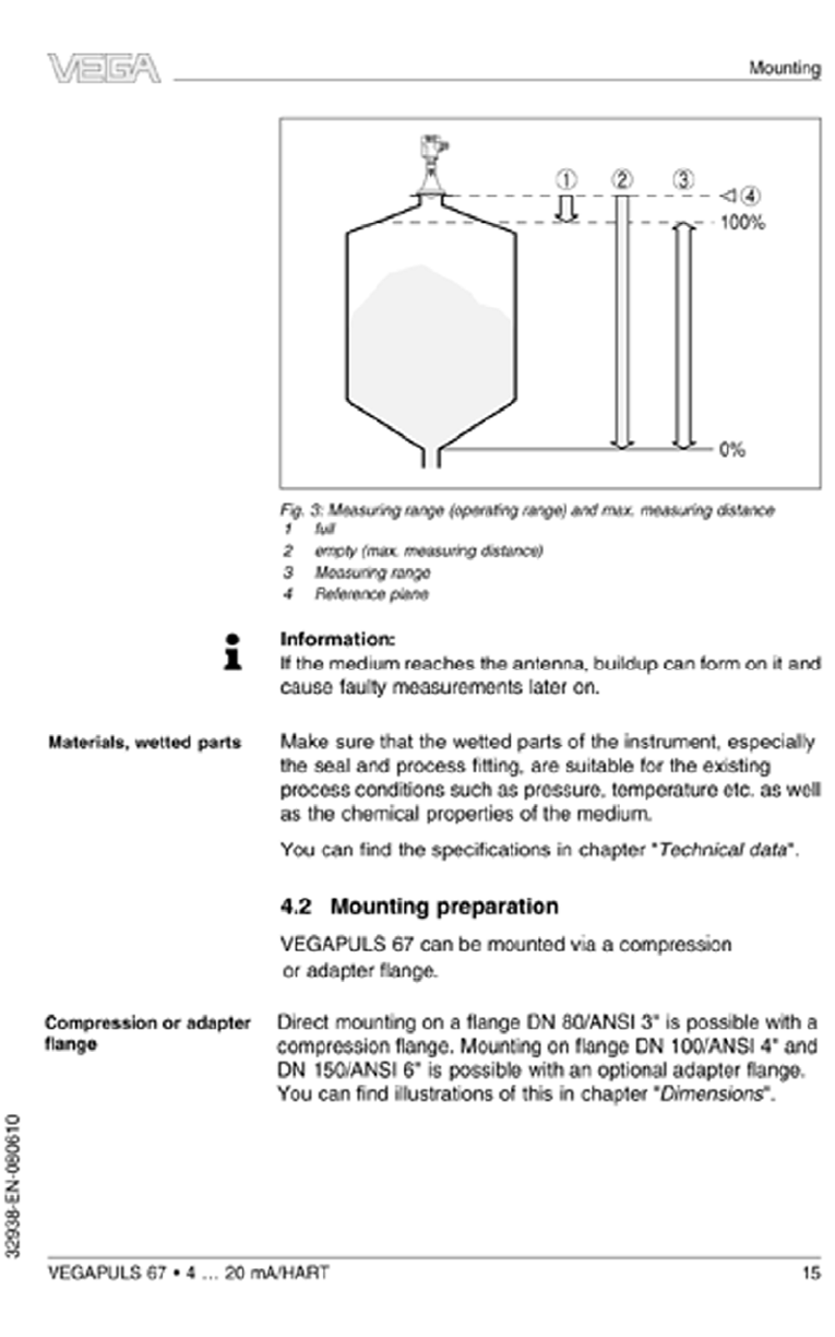
Fig.2:Measures against moisture penetration
The reference plane for the measuring range of the sensors is
the contact surface on the side of the antenna cover.
Mounting position
Moisture
Measuring range
14 VEGAPULS 67 •4…20 mA/HART
Mounting
32938-EN-080610
4Mounting
4.1General instructions
Select an installation position you can easily reach for
mounting and connecting as well as later retrofitting of an
indicating and adjustment module.The housing can be rotated
by 330°without the use of any tools.You can also install the
indicating and adjustment module in four different positions
(each displaced by 90°).
Use the recommended cables (see chapter "Connecting to
power supply")and tighten the cable gland.
You can give your instrument additional protection against
moisture penetration by leading the connection cable down-
ward in front of the cable entry.Rain and condensation water
can thus drain off.This applies mainly to outdoor mounting as
well as installation in areas where high humidity is expected (e.
g.through cleaning processes)or on cooled or heated
vessels.
Fig.2:Measures against moisture penetration
The reference plane for the measuring range of the sensors is
the contact surface on the side of the antenna cover.
Mounting position
Moisture
Measuring range
14 VEGAPULS 67 •4…20 mA/HART
Mounting
32938-EN-080610
The VEGAPULS 67 must be mounted such that it is pointing
downward inside enclosed metal, concrete, or bre-reinforced
plastic vessels only. Any other use is prohibited. Select
an installation position you can easily reach for mounting
and connecting as well as later retrotting of an indicating
and adjustment module. The housing can be rotated by
330° without the use of any tools. You can also install the
indicating and adjustment module in four different positions
(each displaced by 90°).
-