VEGA Americas PULS68 VEGAPULS 68 Radar Sensor User Manual Part 90
VEGA Americas Inc. VEGAPULS 68 Radar Sensor Part 90
Contents
- 1. Manual revised
- 2. Manual
Manual

Rhein Tech Laboratories Client: Ohmart/VEGA
360 Herndon Parkway Model: VEGAPULS 68
Suite 1400 FCC ID: MOIPULS68
Herndon, VA 20170 Standards: FCC 15.209/IC RSS-210
http://www.rheintech.com Report Number: 2004236
APPENDIX E: MANUAL
Please see the following pages.
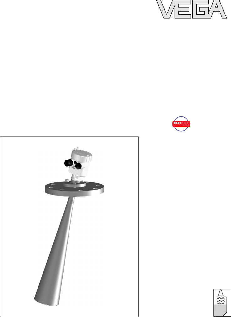
Operating Instructions
VEGAPULS 68
4... 20 mA/HART
ABILITY
WE
'
VE GO
T
O
O

Contents
1About this document
1.1Function ......................... 4
1.2Target group ...................... 4
1.3Symbolism used.................... 4
2For your safety
2.1Authorised personnel ................ 6
2.2Appropriate use .................... 6
2.3Warning about misuse ............... 6
2.4General safety instructions ............ 6
2.5CE conformity ..................... 7
2.6Compatibility acc.to NAMUR NE 53 ..... 7
2.7FCC conformity (only for USA/Canada)... 8
2.8Safety information for Exareas......... 8
2.9Environmental instructions............. 8
3Product description
3.1Configuration ...................... 9
3.2Principle of operation ................ 10
3.3Adjustment........................ 11
3.4Storage and transport ................ 11
4Mounting
4.1General instructions ................. 13
4.2Mounting preparations,horn antenna..... 14
4.3Mounting preparations,parabolic antenna .15
4.4Mounting information ................ 16
5Connecting to power supply
5.1Preparing the connection ............. 22
5.2Connection procedure ............... 23
5.3Wiring plans,single chamber housing .... 24
5.4Wiring plans,double chamber housing ... 26
5.5Wiring plans,double chamber housing Exd.28
2VEGAPULS 68 -4... 20 mA/HART
Contents
29261-EN-050202

6Setup with the indicating and adjustment
module PLICSCOM
6.1Short description ................... 31
6.2Installing the indicating and adjustment
module PLICSCOM ................. 31
6.3Adjustment system .................. 33
6.4Setup procedure ................... 34
6.5Menu schematic.................... 39
7Setup with PACTware™
7.1Connecting the PC .................. 42
7.2Parameter adjustment with PACTware™.. 43
8Maintenance and fault rectification
8.1Maintenance ...................... 45
8.2Fault rectification ................... 45
8.3Exchanging the oscillator ............. 47
8.4Instrument repair ................... 49
9Dismounting
9.1Dismounting procedure............... 51
9.2Disposal ......................... 51
10 Supplement
10.1Technical data ..................... 52
10.2Dimensions ....................... 59
10.3CE declaration of conformity ........... 70
VEGAPULS 68 -4... 20 mA/HART 3
Contents
29261-EN-050202
1About this document
1.1Function
This operating instructions manual has all the informa-
tion you need for quick setup and safe operation of
VEGAPULS 68.Please read this manual before you
start setup.
1.2Target group
This operating instructions manual is directed to trained
personnel.The contents of this manual should be made
available to these personnel and put into practice by
them.
1.3Symbolism used
Information,tip,note
This symbol indicates helpful additional information.
Caution,warning,danger
This symbol informs you of a dangerous situation that
could occur.Ignoring this cautionary note can impair the
person and/or the instrument.
Ex applications
This symbol indicates special instructions for Exap-
plications.
lList
The dot set in front indicates a list with no implied
sequence.
àAction
This arrow indicates a single action.
4VEGAPULS 68 -4... 20 mA/HART
About this document
29261-EN-050202

1Sequence
Numbers set in front indicate successive steps in a
procedure.
VEGAPULS 68 -4... 20 mA/HART 5
About this document
29261-EN-050202

2For your safety
2.1Authorised personnel
All operations described in this operating instructions
manual must be carried out only by trained and
specialist personnel authorised by the operator.For
safety and warranty reasons,any internal work on the
instruments must be carried out only by personnel
authorised by the manufacturer.
2.2Appropriate use
VEGAPULS 68 is a sensor for continuous level
measurement.
2.3Warning about misuse
Inappropriate or incorrect use of the instrument can give
rise to application-specific hazards,e.g.vessel overfill or
damage to system components through incorrect
mounting or adjustment.
2.4General safety instructions
VEGAPULS 68 is a high-tech instrument requiring the
strict observance of standard regulations and guideli-
nes.The emitting frequencies of all VEGAPULS sensors
are in the Cor K-band range (depending on the
instrument version). The low emitted powers are far
below the internationally permitted limit values,in case
of correct use,no health problems are expected.There
are no restrictions in using the instrument also outside
metallic,closed vessels.The user must take note of the
safety instructions in this operating instructions manual,
the country-specific installation standards (e.g.the VDE
regulations in Germany)as well as all prevailing safety
regulations and accident prevention rules.
6VEGAPULS 68 -4... 20 mA/HART
For your safety
29261-EN-050202

2.5CE conformity
VEGAPULS 68 is in CE conformity with EMC (89/336/
EWG), fulfils the Namur recommendation NE 21 and is
in CE conformity with NSR (73/23/EWG).
Conformity has been judged acc.to the following
standards:
lEMC:
-Emission EN 61326:1997 (class B)
-Susceptibility EN 61326:1997/A1:1998
lNSR:EN 61010-1:2001.
2.6Compatibility acc.to NAMUR NE 53
VEGAPULS 68 meets NAMUR recommendation NE 53.
VEGA instruments are generally upward and downward
compatible:
lsensor software of DTM VEGAPULS 68 HART,PA
or FF
lDTM VEGAPULS 68 for adjustment software
PACTware™
ladjustment module PLICSCOM for sensor software
The parameter adjustment of the basic sensor functions
is independent of the software version.The available
functions depend on the appropriate software version of
the single components.
The software version of VEGAPULS 68 can be deter-
mined as follows:
lvia PACTware™
lon the type label of the electronics
lvia the adjustment module PLICSCOM
On our website www.vega.com you will find all software
histories.Use the possibility and get registered for
update information via e-mail.
VEGAPULS 68 -4... 20 mA/HART 7
For your safety
29261-EN-050202

2.7FCC conformity (only for USA/Canada)
VEGAPULS with all antenna versions are FCC ap-
proved.
Modifications must be expressively agreed by VEGA,
otherwise the operating licence acc.to FCC will expire.
VEGAPULS 68 is in conformity with part 15 of the FCC
regulations.Note the respective regulations for opera-
tion:
lThe instrument must not cause any interfering
emissions
lThe instrument must be insensitive to interfering
emissions,also to such causing unwanted operating
conditions.
2.8Safety information for Ex areas
Please note the Ex-specific safety information for
installation and operation in Exareas.These safety
instructions are part of the operating instructions manual
and come with the Ex-approved instruments.
2.9Environmental instructions
Protection of the environment is one of our most
important duties.That is why we have introduced an
environment management system with the goal of
continuously improving company environmental protec-
tion.The environment management system is certified
acc.to DIN EN ISO 14001.
Please help us fulfil this obligation by observing the
environmental instructions in this manual:
lChapter "Storage and transport"
lChapter "Disposal"
8VEGAPULS 68 -4... 20 mA/HART
For your safety
29261-EN-050202

3Product description
3.1Configuration
The scope of delivery encompasses:
lVEGAPULS 68 radar sensor
ldocumentation
-this operating instructions manual
-Ex-specific safety instructions (with Ex versions)
and,if necessary,further certificates
VEGAPULS 68 consists of the following components:
lhorn or parabolic antenna
lprocess fitting (depending on the version flange or
thread)
loptionally available with swivelling holder (only with
flange), rinsing air connection,reflux valve
lhousing with electronics
lhousing cover,optionally available with indicating/
adjustment module PLICSCOM
The components are available in different versions.
Scope of delivery
Components
VEGAPULS 68 -4... 20 mA/HART 9
Product description
29261-EN-050202
1
2
3
4
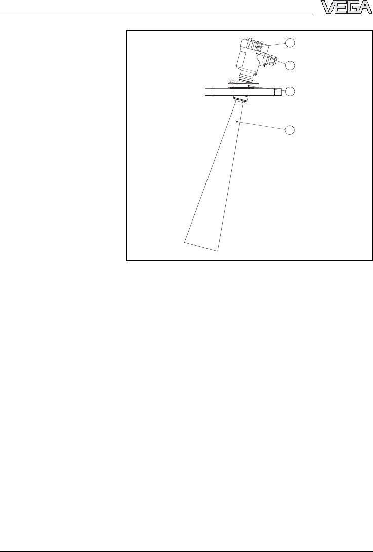
Fig.1:VEGAPULS 68 with horn antenna and swivelling holder
1Housing cover with integrated PLICSCOM (optional)
2Housing with electronics
3Swivelling holder with flange
4Horn antenna
3.2Principle of operation
VEGAPULS 68 is a radar sensor in K-band technology
for continuous level measurement.
Aversion of VEGAPULS 68 is available for the
respective application:
lThe version with horn antenna is particularly suitable
for small silos and vessels for measurement of
virtually all solids.
lThe version with parabolic antenna is particularly
suitable for large silos and vessels with up to 70 m
(76 yd)measuring distance and for measurement of
solids with small dielectric value.
Area of application
10 VEGAPULS 68 -4... 20 mA/HART
Product description
29261-EN-050202

The antenna of the radar sensor emits short radar
pulses with a duration of approx.1ns.These pulses are
reflected by the product and received by the antenna as
echoes.The running time of the radar pulses from
emission to reception is proportional to the distance and
hence to the level.The determined level is converted
into an appropriate output signal and outputted as
measured value.
Two-wire electronics 4... 20 mA/HART for power supply
and measured value transmission on the same cable.
The power supply range can differ depending on the
instrument version.The exact range is stated in the
Technical data in the Supplement.
3.3Adjustment
VEGAPULS 68 can be adjusted with three different
adjustment media:
lthe indicating and adjustment module PLICSCOM
lan adjustment software acc.to FDT/DTM standard,
e.g.PACTware™and PC
laHART handheld
The entered parameters are generally saved in VEGA-
PULS 68,optionally also in PLICSCOM or in
PACTware™.
3.4Storage and transport
Your instrument was protected by packaging during
transport.Its capacity to handle normal loads during
transport is assured by a test acc.to EN 24180.
The packaging of standard instruments consists of
environment-friendly,recyclable cardboard.For special
versions PE foam or PE foil can be also used.Dispose
of the packaging material via specialised recycling
companies.
Physical principle
Power supply
Packaging
VEGAPULS 68 -4... 20 mA/HART 11
Product description
29261-EN-050202

lStorage and transport temperature see Supplement,
Technical data,Ambient conditions
lRelative humidity 20 ... 85 %
Storage and transport
temperature
12 VEGAPULS 68 -4... 20 mA/HART
Product description
29261-EN-050202
4Mounting
4.1General instructions
Select an installation position you can easily reach for
mounting and connecting as well as later retrofitting of
an indicating and adjustment module PLICSCOM.The
housing can be rotated by 330°without the use of any
tools.You can also install the indicating and adjustment
module PLICSCOM in four different positions (each
displaced by 90°).
Use the recommended cable (see chapter "Connecting
to power supply")and tighten the cable entry.
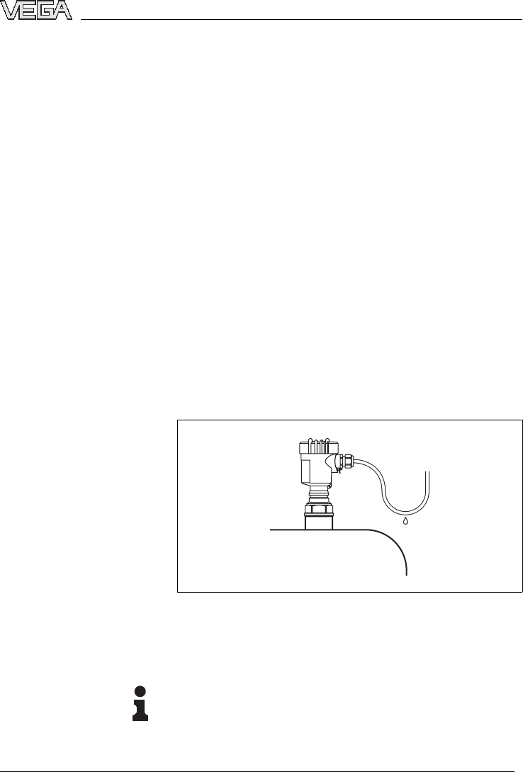
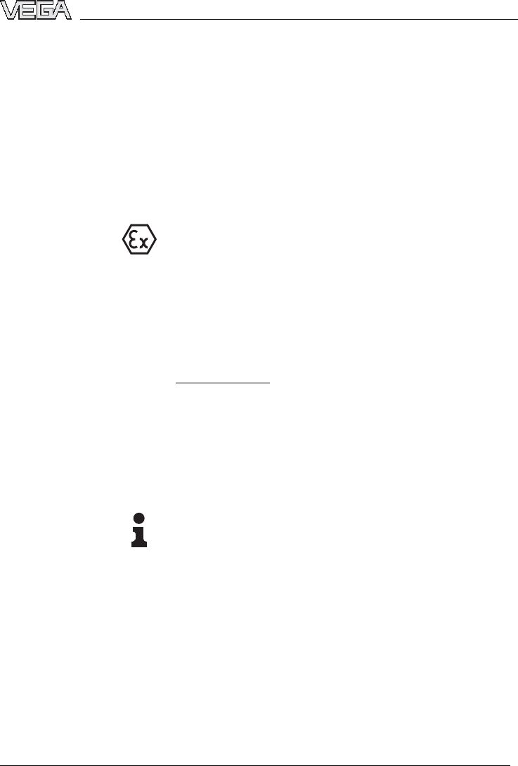
You can give your VEGAPULS 68 additional protection
against moisture penetration by leading the connection
cable downward in front of the cable entry.Rain and
condensation water can thus drain off.This applies
mainly to mounting outdoors,in areas where moisture is
expected (e.g.by cleaning processes)or on cooled or
heated vessels.
Fig.2:Measures against moisture penetration
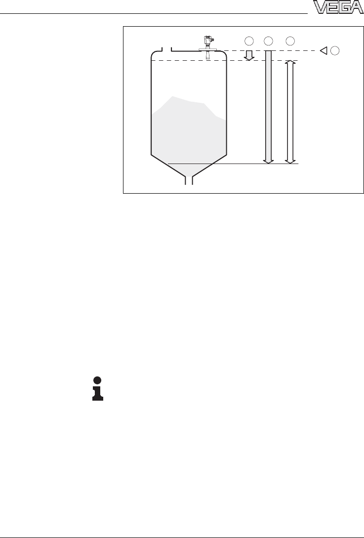
The reference plane for the measuring range is the lower
edge of the flange or the seal surface of the thread.
Information:
If the product reaches the antenna,buildup can form on
it over a period of time and later cause measurement
errors.
Installation position
Moisture
Measuring range
VEGAPULS 68 -4... 20 mA/HART 13
Mounting
29261-EN-050202
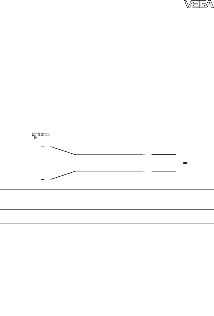
1 32
100%
0%
4
Fig.3:Measuring range (operating range)and max.measuring
distance
1full
2empty (max.measuring distance)
3Measuring range
The process fitting must be sealed with gauge or low
pressure in the vessel.Check before use,if the seal
material is resistant against the measured product.The
max.permissible pressure is stated in the Technical
data in the Supplement or on the type label of the
sensor.
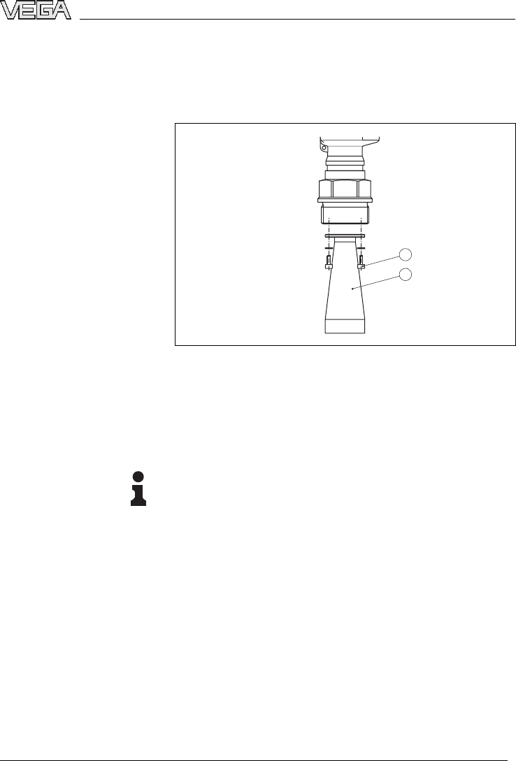
4.2Mounting preparations,horn antenna
Information:
This information applies only to special versions!
VEGAPULS 68 is available in versions where the
antenna has a bigger diameter than the process fitting
(thread/flange). Therefore the antenna must be dis-
mounted on the process fitting before mounting.
Proceed as follows:
1Loosen the hexagon screws on the antenna socket
(1)with an Allan key (size 3)
2Remove the antenna (2)
Pressure
14 VEGAPULS 68 -4... 20 mA/HART
Mounting
29261-EN-050202
3Insert the antenna from below into the vessel socket
and secure it against falling off
4Retighten the antenna with hexagon screws (1)to the
antenna socket;torque max.10 Nm(7.5lbf ft)
1
2
Fig.4:Dismounting of the horn antenna
1Hexagon screws on the antenna socket
2Antenna
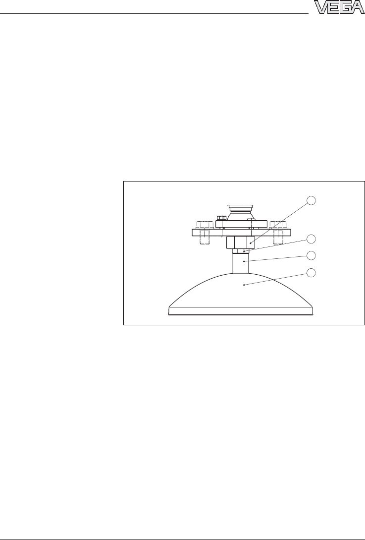
4.3Mounting preparations,parabolic antenna
Information:
This information applies only to special versions!
VEGAPULS 68 is available in versions where the
antenna has a bigger diameter than the process fitting
(thread/flange). Before starting to mount,the antenna
must be dismounted on the flange.Proceed as follows:
1Clamp VEGAPULS 68 with the flange,e.g.in a
bench vice
2Hold the connection piece (3)with a wrench SW 22
on the flattenings
3Unscrew the locknut (2)with SW 36 against the
antenna
4Unscrew the compression nut (1)with a wrench SW
41 against the antenna
VEGAPULS 68 -4... 20 mA/HART 15
Mounting
29261-EN-050202
5Remove the parabolic antenna (4)axially
6Mount sensor flange to the adapter flange and clamp
it
7Check if there is a O-ring seal on the adapter and if it
is not damaged.If necessary,replace it:Viton,article
no.2.28248,Kalrez 6375 article no.2.27351.
8Remount the parabolic antenna (4)
9Tighten compression nut (3)with SW 41,torque max.
50 Nm.
10 Tighten locknut (2)with SW 36,torque max.40 Nm.
1
2
3
4
Fig.5:Dismounting,parabolic antenna
1Compression nut
2Locknut
3Connection piece
4Parabolic antenna
4.4Mounting information
The illustrations on the mounting instructions show a
VEGAPULS 68 with horn antenna.The mounting
instructions also apply to VEGAPULS 68 with parabolic
antenna.
Horn and parabolic anten-
na
16 VEGAPULS 68 -4... 20 mA/HART
Mounting
29261-EN-050202
When mounting the sensor,keep a distance of at least
200 mm (7.9in)to the vessel wall.If the sensor is
installed in the center of concave or arched vessel tops,
multiple echoes can arise.These can,however,be
faded out by an appropriate adjustment (see Setup).
If this distance cannot be maintained,a false echo
storage should be carried out during setup.This applies
particularly if buildup on the vessel wall is expected.In
this case,we recommend repeating the false echo
storage later on with existing buildup.
12
> 200 mm
Fig.6:Installation location
1Reference plane
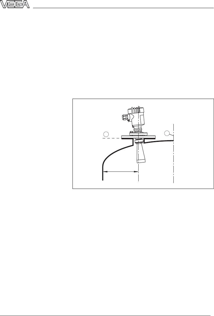
In vessels with conical bottom it can be advantageous to
align the sensor to the center of the vessel,as
measurement is then possible down to the lowest points
of the vessel bottom.
Installation location
VEGAPULS 68 -4... 20 mA/HART 17
Mounting
29261-EN-050202
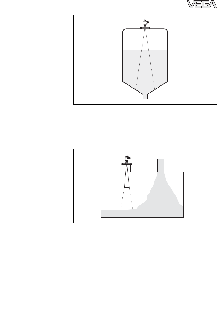
Fig.7:Vessel with conical bottom
Do not mount the instruments in or above the filling
stream.Make sure that you detect the product surface
and not the inflowing product.
Fig.8:Inflowing material
PreferablyVEGAPULS 68 should be mounted without
socket flush to the vessel top.
Inflowing material
Mounting boss
18 VEGAPULS 68 -4... 20 mA/HART
Mounting
29261-EN-050202
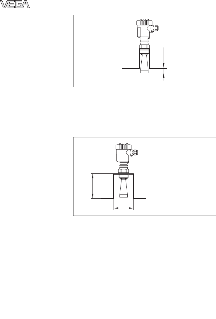
ca. 10 mm
Fig.9:Recommended socket mounting
Ifthereflective properties of the medium are good,you
can mount VEGAPULS 68 on a socket piece.The
socket end should be smooth and burr-free,if possible
also rounded.Carry out a false echo storage.
d
hmax.
d
1½"
50 mm/2"
80 mm/3"
100 mm/4"
150 mm/6"
200 mm
250 mm
300 mm
500 mm
800 mm
hmax.
Fig.10:Deviating socket dimensions
In liquids,direct the sensor as close as vertical to the
product surface to achieve optimum measurement
results.
Sensor orientation
VEGAPULS 68 -4... 20 mA/HART 19
Mounting
29261-EN-050202
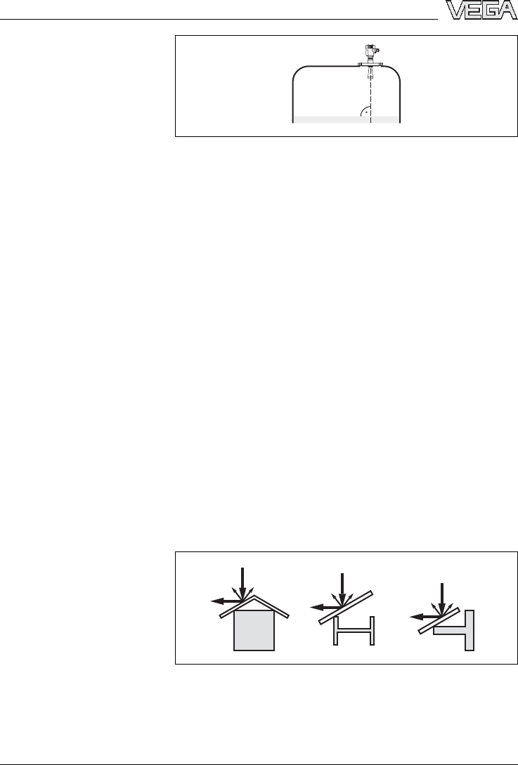
Fig.11:Orientation in liquids
The version with swivelling holder ensures optimum
orientation of the sensor to the solid cone.
Loosen the screw on the swivelling holder with a flat
wrench SW 13,direct the sensor and retighten the
screw,torque max.20 Nm.
The radar sensor should be installed at a location where
no installations cross the radar signals.
Vessel installations such as,for example,ladders,limit
switches,heating spirals,struts,etc.can cause false
echoes superimposed on the useful echo.Make sure
when planning your measuring location that the radar
signals have "free access"to the measured product.
In case of existing vessel installations,a false echo
storage should be carried out during setup.
If large vessel installations such as struts or supports
cause false echoes,these can be attenuated through
supplementary measures.Small,inclined sheet metal
baffles above the installations scatter the radar signals
and avoid a direct false echo reflection.
Fig.12:Cover smooth profiles with deflectors
Vessel installations
20 VEGAPULS 68 -4... 20 mA/HART
Mounting
29261-EN-050202
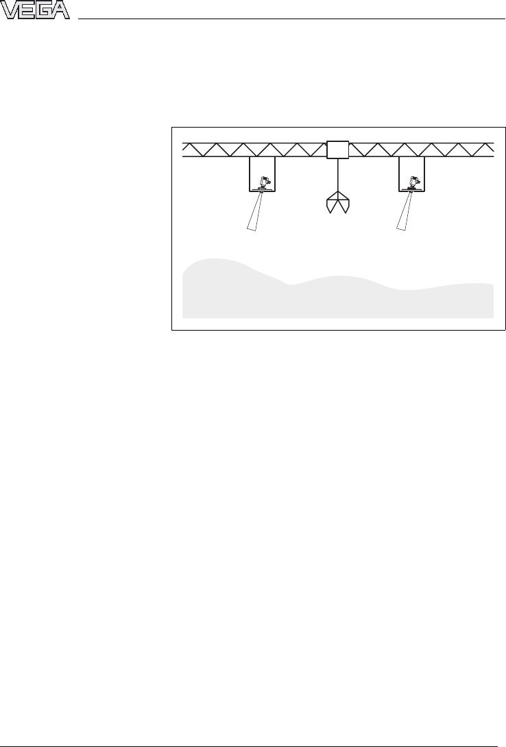
Large material heaps are detected with several instru-
ments,which can be mounted on e.g.traverse cranes.
For this type of application,it is best to orient the sensor
toward the solid surface.
Fig.13:Radar sensors on traverse crane
Material heaps
VEGAPULS 68 -4... 20 mA/HART 21
Mounting
29261-EN-050202
5Connecting to power supply
5.1Preparing the connection
Always observe the following safety instructions:
lConnect only in the complete absence of line voltage
lIf overvoltages are expected,overvoltage arresters
should be installed.
Tip:
We recommend VEGA overvoltage arresters ÜS-F-LB-I
and ÜSB 62-36G.X.
In hazardous areas you should take note of the
appropriate regulations,conformity and type approval
certificates of the sensors and power supply units.
Power supply and current signal are transmitted via the
same two-wire connection cable.The power supply
range can differ depending on the instrument version.
The exact range is stated in the Technical data in the
Supplement.
Provide a reliable separation between the supply circuit
and the mains circuits acc.to DIN VDE 0106 part 101.
The VEGA power supply units VEGATRENN 149AEx,
VEGASTAB 690,VEGADIS 371 as well as all VEGA-
METs meet this requirement.
Bear in mind the following factors regarding supply
voltage:
lthe reduction of the output voltage of the power
supply unit under nominal load (with a sensor current
of 20.5mAor 22 mAin case of fault signal)
lthe influence of additional instruments in the circuit
(see load values in Technical data)
VEGAPULS 68 is connected with standard two-wire
cable without screen.An outer cable diameter of 5...
9mm ensures the seal effect of the cable entry.If
electromagnetic interference is expected,we recom-
mend the use of screened cable.
Note safety instructions
Take note of safety
instructions for Ex
applications
Select power supply
Select connection cable
22 VEGAPULS 68 -4... 20 mA/HART
Connecting to power supply
29261-EN-050202
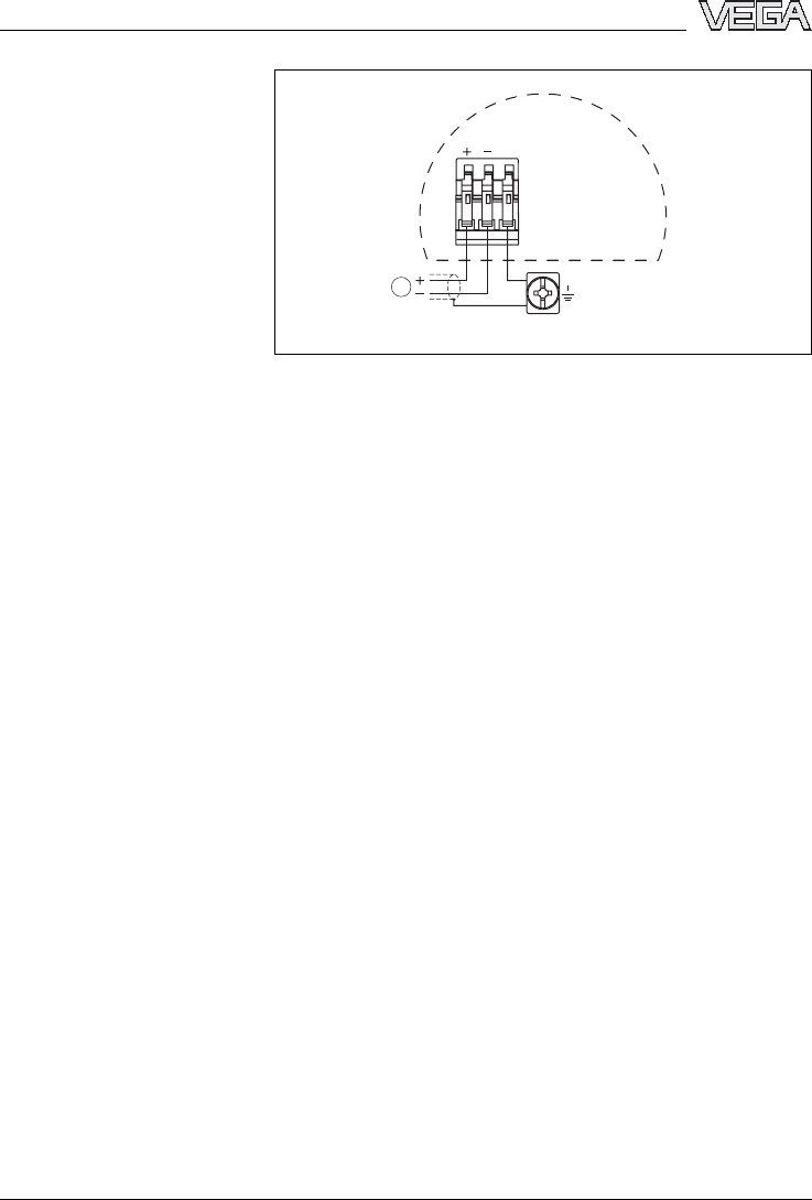
Connect the cable screen on both ends to ground
potential.In the sensor,the screen must be connected
directly to the internal ground terminal.The ground
terminal outside on the housing must be connected to
the potential equalisation (low impedance).
If potential equalisation currents are expected,the
connection on the evaluation side must be made via a
ceramic capacitor (e.g.1nF,1500 V). The low
frequency potential equalisation currents are thus sup-
pressed,but the protective effect against high frequency
interference signals remains.
Take note of the corresponding installation regulations
for Ex applications.In particular,make sure that no
potential equalisation currents flow over the cable
screen.In case of grounding on both sides this can be
achieved by the use of a capacitor or a separate
potential equalisation.
5.2Connection procedure
Proceed as follows:
1Unscrew the housing cover
2IfaPLICSCOM indicating and adjustment module is
installed,remove it by turning it slightly to the left.
3Loosen compression nut of the cable entry
4Remove approx.10 cm (4in)of the cable mantle,
strip approx.1cm (0.4in)insulation from the ends of
the individual wires
5Insert the cable into the sensor through the cable
entry
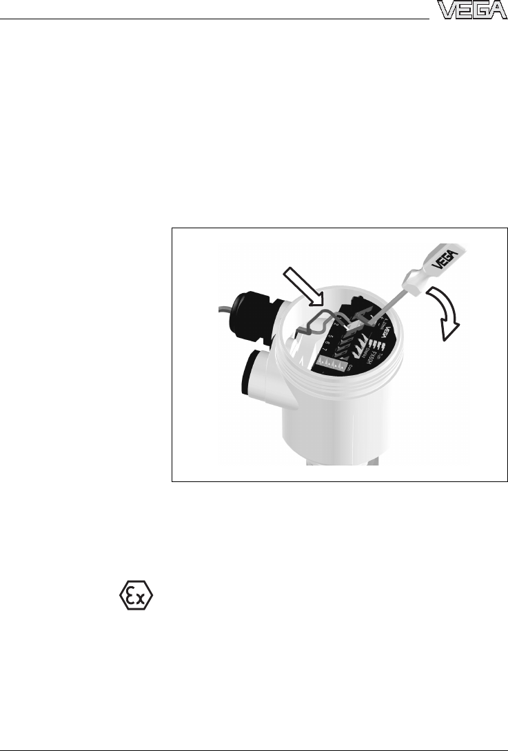
6Lift the opening levers of the terminals with a
screwdriver (see following illustration)
7Insert the wire ends into the open terminals
according to the wiring plan
8Press down the opening levers of the terminals,you
will hear the terminal spring closing
Cable screening and
grounding
Select connection
cable for Ex appli-
cations
VEGAPULS 68 -4... 20 mA/HART 23
Connecting to power supply
29261-EN-050202
9Check the hold of the wires in the terminals by lightly
pulling on them
10 Connect the screen to the internal ground terminal
and the external ground terminal to potential equa-
lisation
11 Tighten the compression nut of the cable entry,the
seal ring must completely encircle the cable
12 Screw the housing cover back on
The electrical connection is finished.
Fig.14:Connection steps 6and 7
5.3Wiring plans,single chamber housing
The following illustrations apply to the non-Exaswellas
to the Ex ia version.
24 VEGAPULS 68 -4... 20 mA/HART
Connecting to power supply
29261-EN-050202
1
4
44
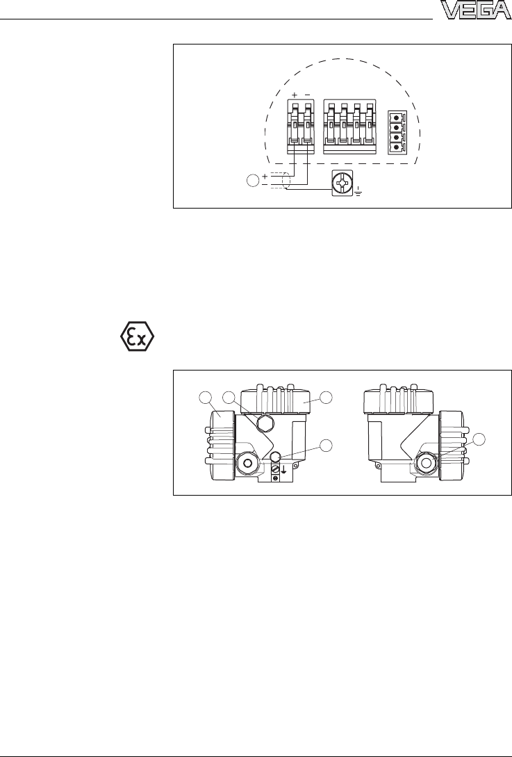
2 3
Fig.15:Material versions,single chamber housing
1Plastic
2Aluminium
3Stainless steel
4Filter element for pressure compensation
Display
Com.
12 5678
3
4
1
2
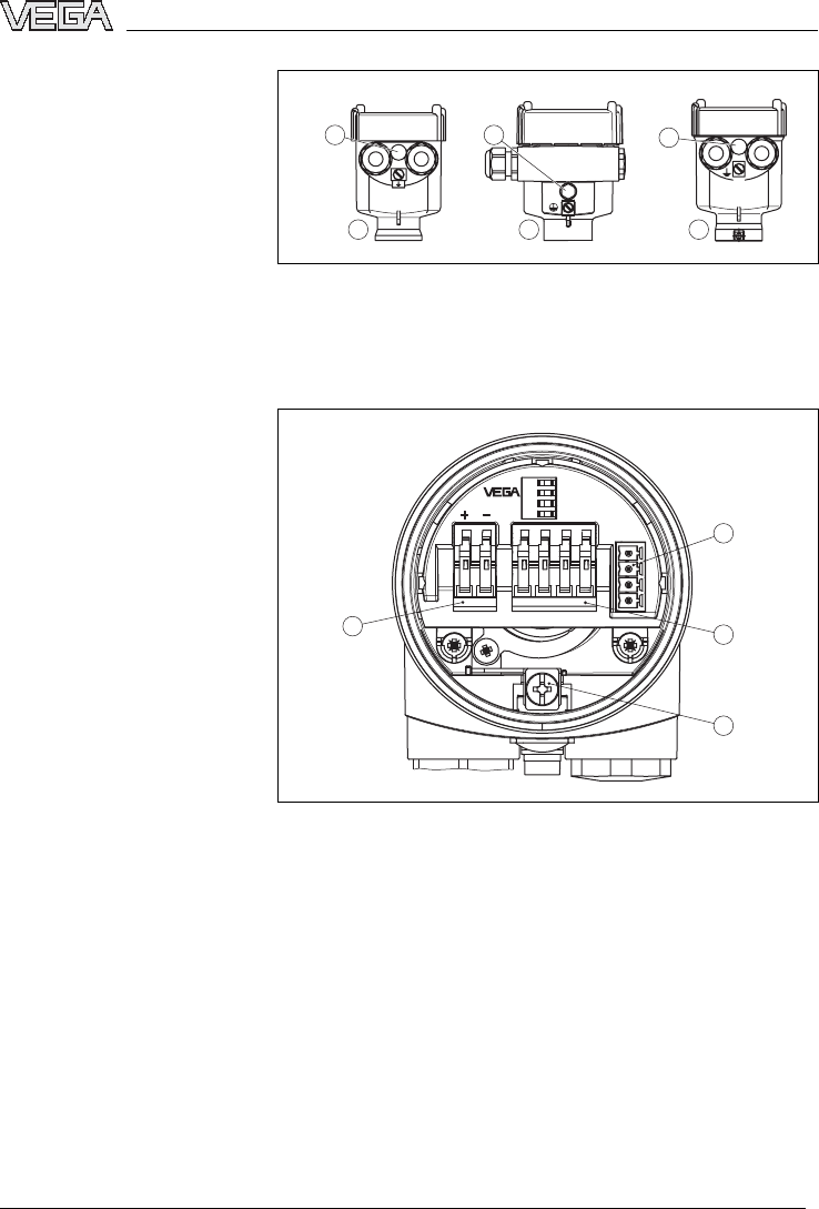
Fig.16:Electronics and connection compartment,single chamber
housing
1Plug connector for VEGACONNECT (I²Cinterface)
2Spring-loaded terminals for connection of the ext.indication
VEGADIS 61
3Ground terminal for connection of the cable screen
4Spring-loaded terminals for power supply and cable screen
Housing overview
Electronics and connec-
tion compartment
VEGAPULS 68 -4... 20 mA/HART 25
Connecting to power supply
29261-EN-050202
Display
1
Com.
12
5
6
7
8
Fig.17:Wiring plan,single chamber housing
1Power supply/Signal output
5.4Wiring plans,double chamber housing
The following illustrations apply to the non-Exaswellas
to the Ex ia version.The Exd version is described in the
next subchapter.
1 2 3
45
Fig.18:Double chamber housing
1Housing cover,connection compartment
2Blind stopper or plug M12x1for VEGADIS 61 (option)
3Housing cover,electronics compartment
4Filter element for pressure compensation
5Cable entry or plug
Wiring plan
Housing overview
26 VEGAPULS 68 -4... 20 mA/HART
Connecting to power supply
29261-EN-050202
1
32
Display
Com.
12 5678
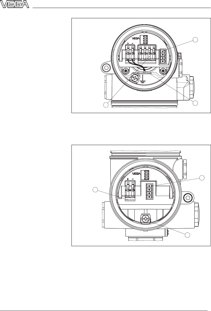
Fig.19:Electronics compartment,double chamber housing
1Plug connector for VEGACONNECT (I²Cinterface)
2Internal connection cable to the connection compartment
3Terminals for VEGADIS 61
3
1
2
Display
Com.
1 2
Fig.20:Connection compartment,double chamber housing
1Plug connector for VEGACONNECT (I²Cinterface)
2Ground terminal for connection of the cable screen
3Spring-loaded terminals for power supply and cable screen
Electronics compartment
Connection compartment
VEGAPULS 68 -4... 20 mA/HART 27
Connecting to power supply
29261-EN-050202
1
Com.
12
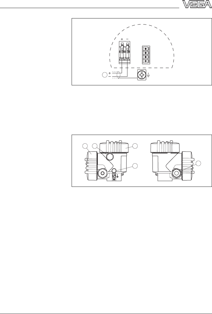
Fig.21:Connection compartment,double chamber housing
1Power supply/Signal output
5.5Wiring plans,double chamber housing
Exd
1 2 3
45
Fig.22:Double chamber housing
1Housing cover,connection compartment
2Blind stopper or plug M12x1for VEGADIS 61 (option)
3Housing cover,electronics compartment
4Filter element for pressure compensation
5Cable entry or plug
Wiring plan
Housing overview
28 VEGAPULS 68 -4... 20 mA/HART
Connecting to power supply
29261-EN-050202
1
32
Display
Com.
12 5678
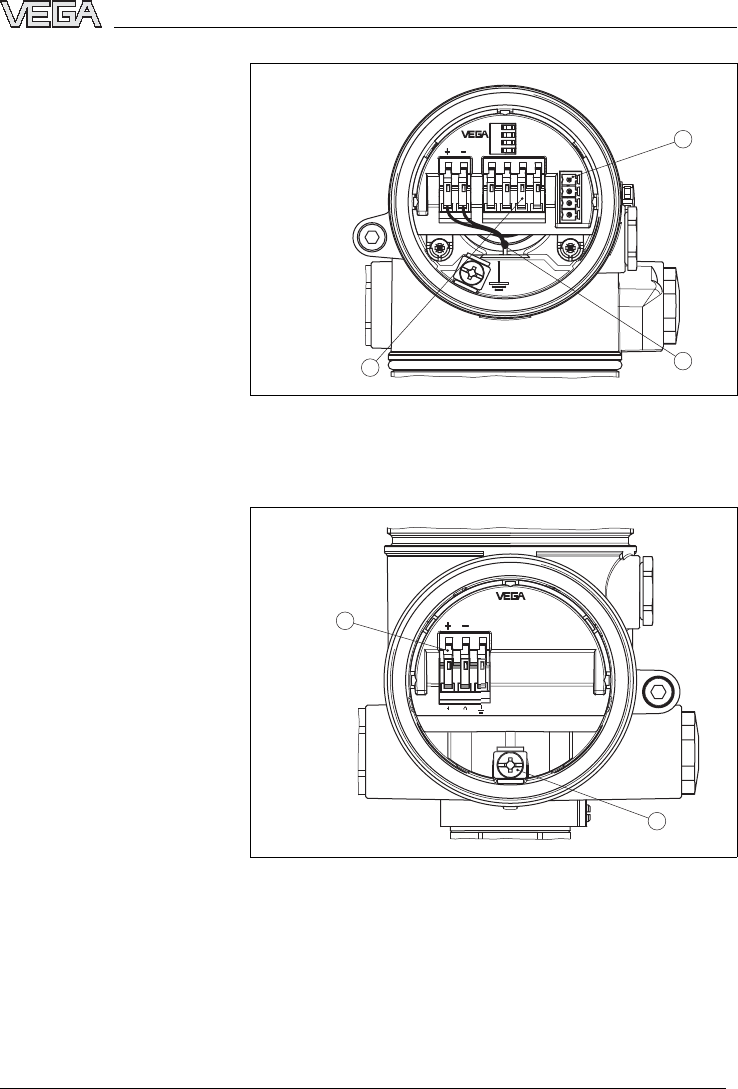
Fig.23:Electronics compartment,double chamber housing
1Plug connector for VEGACONNECT (I²Cinterface)
2Internal connection cable to the connection compartment
3Terminals for VEGADIS 61
1
2
1
2
Fig.24:Connection compartment,double chamber housing Exd
1Spring-loaded terminals for power supply and cable screen
2Ground terminal for connection of the cable screen
Electronics compartment
Connection compartment
VEGAPULS 68 -4... 20 mA/HART 29
Connecting to power supply
29261-EN-050202
1
12
Fig.25:Wiring plan,double chamber housing Exd
1Power supply/Signal output
Wiring plan
30 VEGAPULS 68 -4... 20 mA/HART
Connecting to power supply
29261-EN-050202

6Setup with the indicating and
adjustment module PLICSCOM
6.1Short description
The indicating and adjustment module PLICSCOM is
used for measured value display,adjustment and
diagnosis.It can be mounted in the following housing
versions and instruments:
lAll sensors of the plics
®
instrument family,in the
single as well as in the double chamber housing
(optionally in the electronics or connection
compartment)
lexternal indicating and adjustment unit VEGADIS 61
Note:
You will find detailed information on the adjustment in
the operating instructions manual of the indicating and
adjustment module PLICSCOM.
6.2Installing the indicating and adjustment
module PLICSCOM
PLICSCOM can be inserted or removed at any time.An
interruption of the power supply is not necessary.
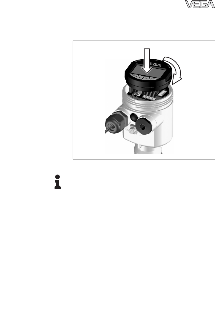
To install,proceed as follows:
1Unscrew the housing cover
2Place PLICSCOM in the desired position on the
electronics (you can choose any one of four different
positions -each displaced by 90°)
3Press PLICSCOM lightly onto the electronics and
turn it to the right until it snaps in.
4Screw housing cover with inspection window tightly
back on
Removal is carried out in reverse order.
Function/Configuration
Insert/remove PLICSCOM
VEGAPULS 68 -4... 20 mA/HART 31
Setup with the indicating and adjustment module PLICSCOM
29261-EN-050202
PLICSCOM is powered by the sensor,an additional
connection is not necessary.
Fig.26:Installation of PLICSCOM
Note:
If you intend to retrofitVEGAPULS 68 with PLICSCOM
for continuous measured value indication,a higher cover
with an inspection glass is required.
32 VEGAPULS 68 -4... 20 mA/HART
Setup with the indicating and adjustment module PLICSCOM
29261-EN-050202
6.3Adjustment system
1.1
2
3
1
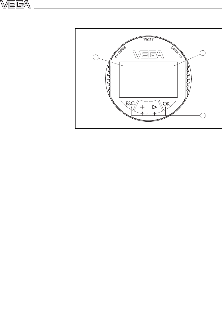
Fig.27:Indicating and adjustment elements
1LC display
2Indication of the menu item number
3Adjustment keys
l[OK]key:
-move to the menu overview
-confirm selected menu
-edit parameter
-save value
l[–>]key to select:
-menu change
-list entry
-editing position
l[+]key:
-modify value of a parameter
l[ESC]key:
-interrupt input
-jump to the next higher menu
The sensor is adjusted via the four keys of the indicating
and adjustment module PLICSCOM.The LC display
indicates the individual menu items.The functions of the
individual keys are shown in the above illustration.
Approx.10 minutes after the last pressing of a key,an
automatic reset to measured value indication is trigger-
Key functions
Adjustment system
VEGAPULS 68 -4... 20 mA/HART 33
Setup with the indicating and adjustment module PLICSCOM
29261-EN-050202
ed.Any values not confirmed with [OK]will not be
saved.
6.4Setup procedure
After VEGAPULS 68 is connected to power supply or
after voltage recurrence,the instrument carries out a
self-test for approx.30 seconds.The following steps are
carried out:
linternal check of the electronics
lindication of the instrument type,the firmware version
as well as the sensor TAGs(sensor name)
lOutput signal jumps briefly(approx.10 seconds)to
the set interference current.
Then the actual measured value is displayed and the
corresponding current is transmitted to the cable1)
InHART-Multidrop mode (several sensors on one input)
the address must be set before continuing with the
parameter adjustment.You will find a detailed descrip-
tion in the operating instructions manual of PLICSCOM
or in the online help of PACTware™or DTM.
HART mode
Standard
Address 0
Because VEGAPULS 68 is a distance measuring
instrument,the distance from the sensor to the product
surface is measured.In order to have the actual level
displayed,an allocation of the measured distance to the
percentage height must be carried out.To make this
adjustment,the full and empty distances in the vessel
are entered.If these values are not known,it is also
possible to carry out the adjustment with other distan-
ces,e.g.10 %and 90 %.Starting point of these distance
values is always the seal surface of the thread or flange.
The actual level is then calculated on the basis of these
1)The values correspond to the actual level as well as to the settings
already carried out,e.g.default setting.
Switch on phase
Address setting HART-
Multidrop
Parameter adjustment
34 VEGAPULS 68 -4... 20 mA/HART
Setup with the indicating and adjustment module PLICSCOM
29261-EN-050202
entered values.At the same time,the operating range of
the sensor is limited from maximum range to the
requested range.
The real product level during this adjustment is not
important,because the min./max.adjustment is always
carried out without changing the product level.These
settings can be made ahead of time without the
instrument having to be installed.
In the main menu item Basic adjustment,the individual
submenu items should be selected one after the other
provided with the correct parameter values.
Start your parameter adjustment with the following menu
items of the basic adjustment:
Proceed as follows:
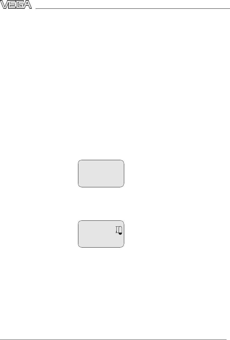
1Move from the measured value display to the main
menu by pushing [OK].
>
Basic adjustment
Display
Diagnostics
Service
Info
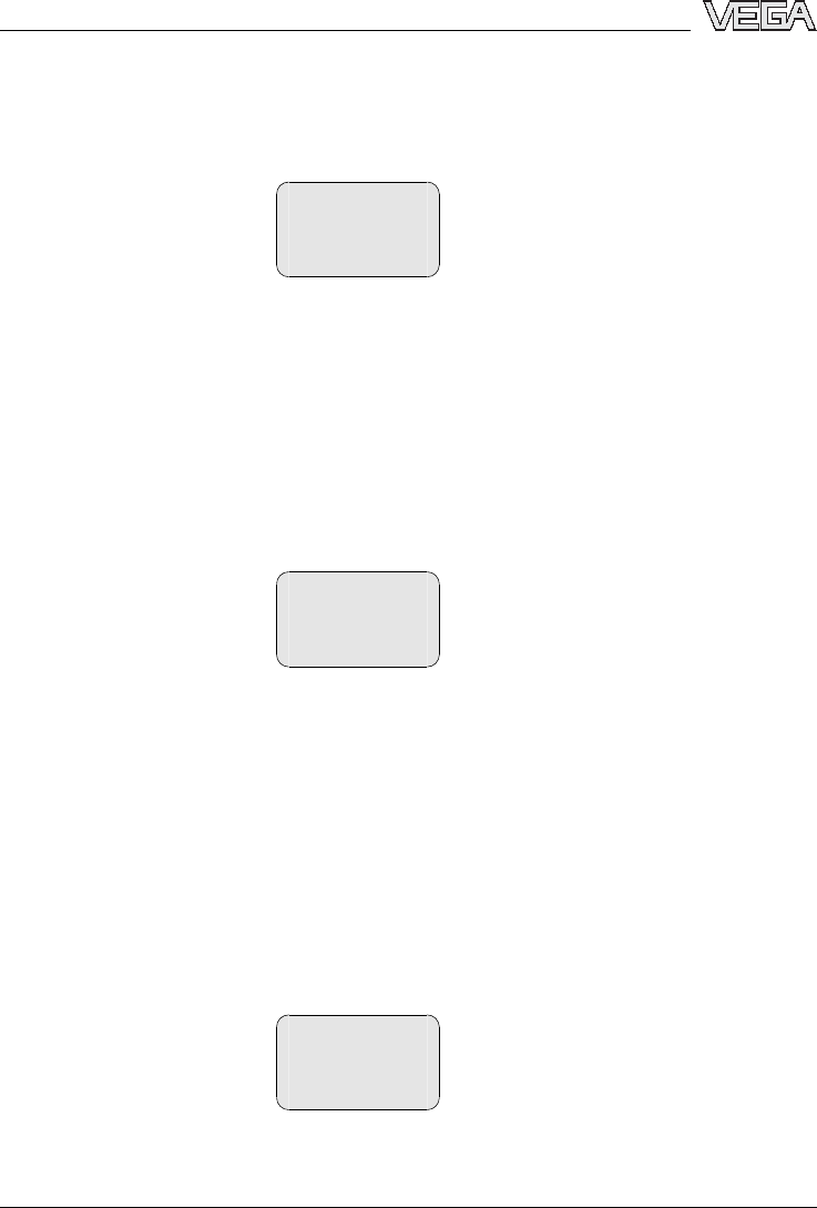
2Select the menu item Basic adjustment with [–>]and
confirm with [OK].Now the menu item min.adjust-
ment is displayed.
Min.adjustment
0.00 %
=
5.000 m(d)
4.000 m(d)
3Prepare the percentage value for editing with [OK]
and set the cursor to the requested position with [–>].
Set the requested percentage value with [+]and
save with [OK].The cursor jumps now to the
distance value.
4Enter the appropriate distance value in m (corre-
sponding to the percentage value)for the empty
vessel (e.g.distance from the sensor to the vessel
bottom).
Carrying out min.adjust-
ment
VEGAPULS 68 -4... 20 mA/HART 35
Setup with the indicating and adjustment module PLICSCOM
29261-EN-050202

5Save the settings with [OK]and move to max.
adjustment with [–>].
Proceed as follows:
Max.adjustment
100.00 %
=
1.000 m(d)
2.000 m(d)
1Prepare the percentage value for editing with [OK]
and set the cursor to the requested position with [–>].
Set the requested percentage value with [+]and
save with [OK].The cursor jumps now to the
distance value.
2Enter the appropriate distance value in m (corre-
sponding to the percentage value)for the full vessel.
Make sure that the max.level must be beneath the
dead zone.
3Save the settings with [OK]and move to the medium
selection with [–>].
Each product has different reflective properties.In
solids,these are dust generation,material cones and
additional echoes caused by the vessel wall.Due to the
medium selection,the sensor is adapted in an optimum
way to the product and the accuracy,particularly for
products with bad reflective properties,is increased
considerably.
Medium
Solid
For solids you choose also Powder/Dust,Granular/
Pellets or Ballast/Pebbels.
In liquids,fluctuating surfaces and foam generation are
further interfering factors.To adapt the sensor to the
different conditions,a general selection is made in this
menu item,i.e.Solid or Liquid.
Carrying out max.adjust-
ment
Medium selection
36 VEGAPULS 68 -4... 20 mA/HART
Setup with the indicating and adjustment module PLICSCOM
29261-EN-050202

Enter the requested parameter via the respective keys,
save your settings and jump to the next menu item with
the [–>]key.
Apart from the medium also the vessel form can
influence the measurement.To adapt the sensor to
these conditions,this menu item offers (depending on
either liquid or solid is selected)different options.For
Liquid these are Storage tank,Stilling tube,Open vessel
or Stirred vessel,for Solid Silo or Bunker.
Vessel form
Silo
Enter the requested parameter via the respective keys,
save your settings and jump to the next menu item with
the [–>]key.
To suppress fluctuation in the measured value display,
e.g.by agitated product surfaces,an integration time
can be set.This time can be between 0and 999
seconds.Please note that the reaction time of the entire
measurement will be longer and the sensor will react to
quick changes of the measured value with a corre-
sponding delay.In general,a time of a few seconds is
sufficient to smooth the measured value display.
Damping
0s
Enter the requested parameter via the respective keys,
save your settings and jump to the next menu item with
the [–>]key.
Alinearization is necessary for all vessels in which the
vessel volume does not increase linearly with the level -
e.g.in a cylindrical or spherical tank -and the indication
or output of the volume is requested.Corresponding
linearization curves are preprogrammed for these
vessels.They represent the correlation between the
level percentage and vessel volume.By activating the
Vessel form
Damping
Linearization curve
VEGAPULS 68 -4... 20 mA/HART 37
Setup with the indicating and adjustment module PLICSCOM
29261-EN-050202
appropriate curve,the volume percentage of the vessel
is displayed correctly.If the volume should not be
displayed in percent but e.g.in l or kg,a scaling can be
set in the menu item Display.
Linearization curve
linear
Enter the requested parameter via the respective keys,
save your settings and jump to the next menu item with
the [–>]key.
In this menu item you can enter an unambiguous
designation for the sensor,e.g.the measurement loop
name or the tank or product designation.In digital
systems and in the documentation of larger plants,a
unique designation should be entered for exact identi-
fication of individual measuring sites.
Sensor-TAG
Sensor
With this menu item,the Basic adjustment is finished
and you can now jump to the main menu with the [ESC]
key.
High sockets or vessel installations,such as e.g.struts
or agitators as well as buildup and weld joints on the
vessel walls cause false reflections which influence the
measurement.Afalse echo storage detects and marks
these false echoes so that they are no longer taken into
account for the level measurement.Afalse echo
memory should be created with empty vessel so that all
probably existing false reflections can be detected.
False echo storage
Change?
Proceed as follows:
Sensor-TAG
False echo storage
38 VEGAPULS 68 -4... 20 mA/HART
Setup with the indicating and adjustment module PLICSCOM
29261-EN-050202

1Move from the measured value display to the main
menu by pushing [OK].
2Select the menu item Service with [–>]and confirm
with [OK].Now the menu item false echo storage is
displayed.
3Confirm False echo storage -Change now with [OK]
and select in the below menu Create new.Enter the
actual distance from the sensor to the product
surface.All false echoes in this area are detected by
the sensor and saved after confirming with [OK].
Note:
Check the distance to the product surface as in case of
awrong(too big)setting,the real level will be saved as
false echo.Hence the level can no longer be detected in
this area.
Additional adjustment and diagnosis options such as e.
g.scaling,simulation or trend curve presentation are
shown in the following menu schematic.You will find a
detailed description of these menu items in the operating
instructions manual of the indicating and adjustment
module PLICSCOM.
Optional settings
VEGAPULS 68 -4... 20 mA/HART 39
Setup with the indicating and adjustment module PLICSCOM
29261-EN-050202
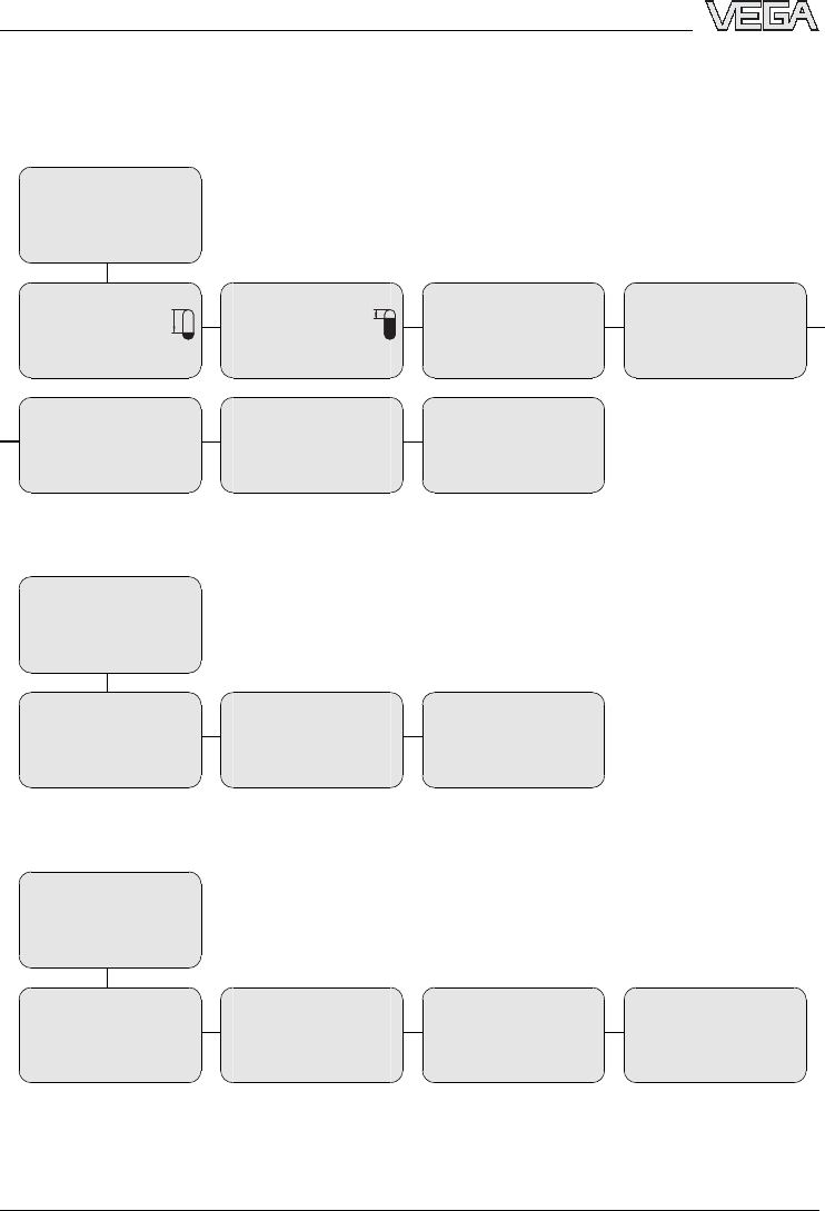
6.5Menu schematic
Basic adjustment
1
>
Basic adjustment
Display
Diagnostics
Service
Info
1.1
Min.adjustment
0.00 %
=
4.000 m(d)
3.000 m(d)
1.2
Max.adjustment
100.00 %
=
1.000 m(d)
2.000 m(d)
1.3
Medium
Solid
1.4
Vessel form
Silo
1.5
Damping
0s
1.6
Linearization curve
linear
1.7
Sensor-TAG
Sensor
Display
2
Basic adjustment
>
Display
Diagnostics
Service
Info
2.1
Displayed value
scaled
2.2
Display units
Volume
m³
2.3
Scaling
0%=0.0m³
100 %=100 m³
Diagnostics
3
Basic adjustment
Display
>
Diagnostics
Service
Info
3.1
Peak values
Distance-min:0.234m(d)
Distance-max:5.385m(d)
3.2
Meas.reliability
8db
Sensor status
OK
3.3
Choose curve
echo curve
3.4
echo curve
Presentation of
echo curve
40 VEGAPULS 68 -4... 20 mA/HART
Setup with the indicating and adjustment module PLICSCOM
29261-EN-050202
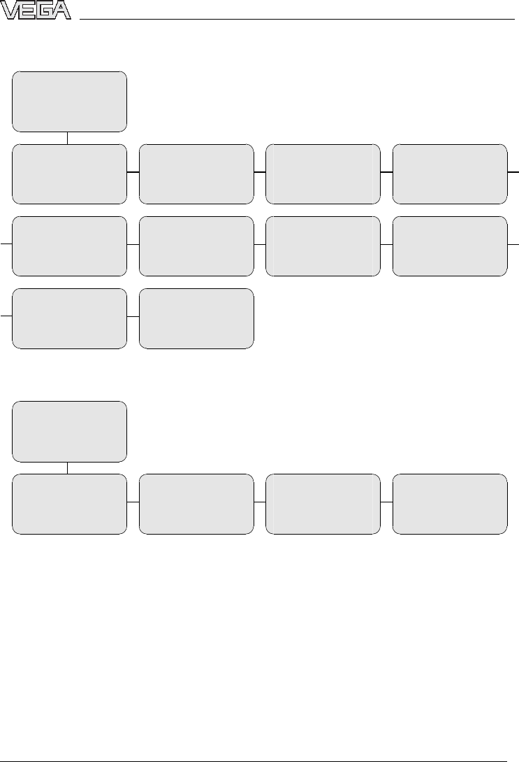
Service
4
Basic adjustment
Display
Diagnostics
>
Service
Info
4.1
False echo storage
Change?
4.2
Addl.adjustments
none
4.3
Current output
Output mode 4-20 mA
Failure mode <3.6mA
min.current 3.8mA
4.4
Simulation
Simulation
start?
4.5
Reset
Reset
select?
4.6
Units of measurement
m(d)
select?
4.7
Language
Deutsch
4.8
HART mode
Standard
Address 0
4.9
Copy sensor data
Copy sensor data?
4.10
PIN
Enable?
Info
5
Basic adjustment
Display
Diagnostics
Service
>
Info
5.1
Sensor type
VEGAPULS 6x
Serial number
12345678
5.2
Date of manufacture
26.March 2004
Software version
3.12.00
5.3
Date of last change
using PC
26.March 2004
5.4
Sensor details
Now
display
VEGAPULS 68 -4... 20 mA/HART 41
Setup with the indicating and adjustment module PLICSCOM
29261-EN-050202
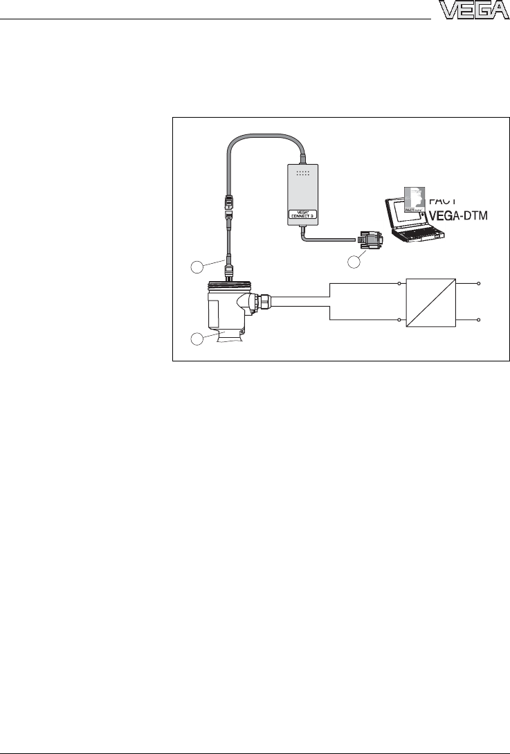
7Setup with PACTware™
7.1Connecting the PC
~
=
Power supply
VE
G
A
CO
NNE
C
T
3
PACTware /
TM
>PA<
2
31
Fig.28:Connecting the PC directly to the sensor
1RS232 connection
2VEGAPULS 68
3I²Cadapter cable for VEGACONNECT 3
Necessary components:
lVEGAPULS 68
lPC with PACTware™and suitable VEGA-DTM
lVEGACONNECT 3with I²Cadapter cable (article no.
2.27323)
lpower supply unit
Connecting the PC directly
to the sensor
42 VEGAPULS 68 -4... 20 mA/HART
Setup with PACTware™
29261-EN-050202
2
3
1
4
~
=
Power supply
VEGACONNECT 3
PACTware /
TM
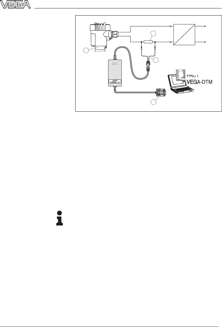
Fig.29:Connecting the PC to the signal cable
1RS232 connection
2VEGAPULS 68
3HART adapter cable for VEGACONNECT 3
4HART resistance 250 Ohm
Necessary components:
lVEGAPULS 68
lPC with PACTware™and suitable VEGA-DTM
lVEGACONNECT 3with HART adapter cable (art.
no.2.25397)
lHART resistance approx.250 Ohm
lpower supply unit
Note:
With power supply units with integrated HART resis-
tance (internal resistance approx.250 Ohm), an addi-
tional external resistance is not necessary (e.g.
VEGATRENN 149A,VEGADIS 371,VEGAMET 381). In
such cases,VEGACONNECT 3can be connected in
parallel to the 4... 20 mAcable.
7.2Parameter adjustment with PACTware™
Further setup steps are described in the operating
instructions manual DTM Collection/PACTware atta-
ched to each CD and which can also be downloaded
Connecting the PC to the
signal cable
VEGAPULS 68 -4... 20 mA/HART 43
Setup with PACTware™
29261-EN-050202

from our homepage.Adetailed description is available
in the online help of PACTware™and the VEGA-DTMs.
Note:
Keep in mind that for setup of VEGAPULS 68,DTM-
Collection 04/2004 or a newer version should be
applied.
All currently available VEGA-DTMs are provided in the
DTM Collection on CD and can be bought from the
responsible VEGA agency for a token fee.This CD
includes also the up-to-date PACTware™version.The
basic version of this DTM Collection incl.PACTware™
is also available as a free-of-charge download from the
Internet.
44 VEGAPULS 68 -4... 20 mA/HART
Setup with PACTware™
29261-EN-050202

8Maintenance and fault rectification
8.1Maintenance
When used as directed in normal operation,VEGAPULS
68 is completely maintenance-free.
8.2Fault rectification
VEGAPULS 68 offers maximum reliability.Nevertheless,
faults may occur during operation.These can have the
following causes,e.g.:
lSensor
lProcess
lPower supply
lSignal processing.
The first measures to be taken are to check the output
signal and evaluate fault messages via the adjustment
module PLICSCOM.The procedure is described below.
Further comprehensive diagnostics can be carried out
on a laptop with the software PACTware™and the
suitable DTM.In many cases,the reasons can be
determined in this way and faults can be rectified.
Should these measures not be successful,please call in
urgent cases the VEGA service hotline under the phone
number +49 1805 858550.
The hotline is available to you 7days a week round-the-
clock.Since we offer this service world-wide,the
support is only available in the English language.The
service is free of charge,only the standard telephone
costs will be charged.
Connect a hand-held multimeter with a suitable measu-
ring range acc.to the wiring plan.
?4... 20 mAsignal is not stable
llevel fluctuations
àset integration time via PLICSCOM or
PACTware™
Causes of failure
Fault rectification
24 hour service hotline
Checking the 4... 20 mA
signal
VEGAPULS 68 -4... 20 mA/HART 45
Maintenance and fault rectification
29261-EN-050202
?4... 20 mAsignal missing
lincorrect connection to power supply
àcheck connection acc.to chapter "Connection
procedure"and correct,if necessary,acc.to
chapter "Wiring plans"
lno power supply
àcheck cables for line break,repair,if necessary
lsupply voltage too low or load resistance too high
àcheck and adapt,if necessary
?Current signal greater than 22 mAor less than 3.6
mA
lElectronics module defective
àexchange instrument or return it for repair
InEx applications,the regulations for the wiring of
intrinsically safe circuits must be observed.
?E013
lno measured value available
àsensor in boot phase
àsensor does not find an echo,e.g.through
incorrect installation or wrong parameter adjust-
ment
?E017
ladjustment span too small
àCarry out a fresh adjustment and increase the
distance between min.and max.adjustment
Fault messages via
PLICSCOM
46 VEGAPULS 68 -4... 20 mA/HART
Maintenance and fault rectification
29261-EN-050202

?E036
lno operable sensor software
àcarry out a software update or return instrument
for repair
?E041
lhardware error,electronics defective
àexchange instrument or return it for repair
8.3Exchanging the oscillator
If the electronics module is defective,it can be replaced
by the user
Oscillator PS-E.60SH.is suitable for VEGAPULS 68 –4
... 20 mA/HART.The following versions are available:
lPS-E.60SHX(without approvals)
lPS-E.60SHC(approvals XM,CX,CM,CK,CI,DX,
DM,DK,DI;EX,GX,UX,UF acc.to VEGA product
list)
InEx applications,only an oscillator with appropriate Ex
approval must be used.
If there is no oscillator available on site,it can be ordered
from the responsible VEGA agency.
The new oscillator must be according to the order data
of the sensor.These can be loaded as follows:
lat the premises by VEGA
lon site by the user.
Information:
When loading on site,first of all the respective file must
be downloaded from the Internet (see Setup).
In both cases,the serial number of VEGAPULS 68 is
necessary.The serial numbers are stated on the type
label of VEGAPULS 68 or on the delivery note.
Preparations
VEGAPULS 68 -4... 20 mA/HART 47
Maintenance and fault rectification
29261-EN-050202
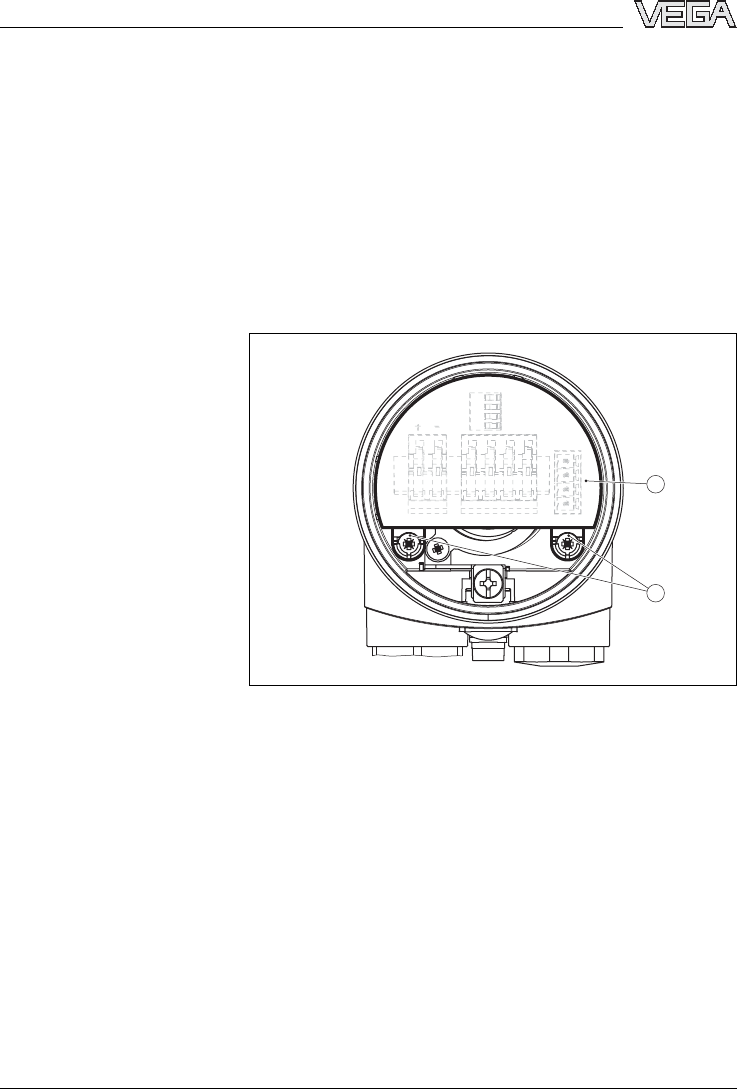
Proceed as follows:
1Switch offpower supply
2Unscrew the housing cover
3Lift the opening levers of the terminals with a
screwdriver
4Pull the connection cables out of the terminals
5Loosen the two screws with a Phillips screwdriver
(size 1)
2
1
Fig.30:Loosen the screws
1Electronics module
2Screws (2pcs.)
6Pull the existing oscillator out by holding the opening
levers.
7Compare the new oscillator with the old one.The
statements on the type label must correspond.This
applies particularly to instruments in Exareas.
8Insert the oscillator
9Screw in and tighten the two screws with a Phillips
screwdriver.
10 Insert the wire ends into the open terminals
according to the wiring plan
Exchange
48 VEGAPULS 68 -4... 20 mA/HART
Maintenance and fault rectification
29261-EN-050202
11 Close the opening levers of the terminals,you will
hear the terminal spring closing
12 Check the hold of the wires in the terminals by lightly
pulling on them
13 Check the tightness of the cable entry.The seal ring
must completely encircle the cable.
14 Screw the housing cover back on
The electronics exchange is finished.
As a rule,the exchange of the oscillator must be
documented internally when used in Ex applications.
If the serial number of the oscillator is stated when
ordering,VEGAPULS 68 is ready for operation directly
after mounting the oscillator.
If you are using an universal electronics from stock,you
have to load the sensor data after mounting the
oscillator.Use the item "serial number search"under
www.vega.com.After having entered the serial number,
the order data of the sensor will be displayed.Below the
order data you will find "Sensor data for Service-DTM"
as an XML file.Load this file to your PC and then into the
sensor via PACTware™/Service DTM.
After VEGAPULS 68 is ready for operation,settings
carried out on site must be repeated.
Tip:
Use the copy function of the adjustment module
PLICSCOM or the adjustment software PACTware™.
8.4Instrument repair
If it is necessary to repair VEGAPULS 68 please
proceed as follows:
You can download a return form (23 KB)from our
Internet homepage www.vega.com under "Services >
Downloads >Forms and Certificates >Repair form.
Setup
VEGAPULS 68 -4... 20 mA/HART 49
Maintenance and fault rectification
29261-EN-050202

By doing this you help us carry out the repair quickly and
without having to call for additional information.
lPrint and fill out one form per instrument
lClean the instrument and pack it damage-proof
lAttach the completed form and possibly also a safety
data sheet to the instrument
lSend the instrument to the respective address of
your agency.InGermany to the VEGA headquarters
in Schiltach.
50 VEGAPULS 68 -4... 20 mA/HART
Maintenance and fault rectification
29261-EN-050202

9Dismounting
9.1Dismounting procedure
Warning:
Before dismounting,be aware of dangerous process
conditions such as e.g.pressure in the vessel,high
temperatures,corrosive or toxic products etc.
Take note of chapters "Mounting"and "Connecting to
power supply"and carry out the listed steps in reverse
order.
9.2Disposal
VEGAPULS 68 consists of materials which can be
recycled by specialised recycling companies.Wehave
purposely designed the electronic modules to be easily
separable.Mark the instrument as scrap and dispose of
it according to government regulations (electronic scrap
ordinance, ...)
Materials:see Technical data
If you cannot dispose of the instrument properly,please
contact us about disposal methods or return.
VEGAPULS 68 -4... 20 mA/HART 51
Dismounting
29261-EN-050202

10 Supplement
10.1Technical data
General data
Materials,non-wetted parts
-housing plastic PBT (Polyester), Alu-die casting
powder-coated,316L(stainless steel
1.4435)
-seal ring between housing and
housing cover
NBR (stainless steel housing), silicone
(Alu/plastic housing)
-inspection window in housing
cover for PLICSCOM
Polycarbonate
-ground terminal stainless steel 1.4571/1.4435
Materials,wetted parts
-process fitting thread G1½Aand 1½NPT,flanges DN 50
... DN 200 and 2"... 8":316 L(stainless
steel 1.4435)
-Antenna 316 L(stainless steel 1.4435), PTFE (TFM
1600 PTFE)
-seal,antenna system Viton,Kalrez 2035,6230,6375,6623
Weight with horn antenna
-process fitting,thread 2.0... 2.8kg (4.4... 6.2lbs), depending on
the thread size and housing
-process fitting,flange 4.2... 15.4kg (9.3... 34 lbs), depending
on the flange size and housing
-process fitting swivelling holder
with flange
5.2... 16.4kg (11.5... 35.2lbs), depen-
ding on the flange size and housing
Weight with parabolic antenna
-process fitting,thread 2.8... 3.6kg (6.2... 13.7lbs), depending
on the thread size and housing
-process fitting,flange 5.0... 16.2kg (11 ... 35.7lbs), depending
on the flange size and housing
-process fitting swivelling holder
with flange
6.0... 17.2kg (13.2... 37.9lbs), depen-
ding on the flange size and housing
52 VEGAPULS 68 -4... 20 mA/HART
Supplement
29261-EN-050202

Output variable
Output signal 4... 20 mA/HART
Resolution 1.6µA
Fault signal current output unchanged,20.5mA,
22 mA,<3.6mA(adjustable)
Current limitation 22 mA
Load see load diagram in Power supply
Integration time (63%of the input
variable)
0... 999 s,adjustable
Rise time 150 ms (ti:0s,0... 100 %)
Fulfilled Namur recommendation NE 43
Input variable
Parameter distance between process fitting and
product surface
Min.distance from antenna end 400 mm (15.7in)
max.measuring range 60 m(197 ft), optionally 70 m(230 ft)
Accuracy (similar to DIN EN 60770-1)
Reference conditions acc.to DIN EN 61298-1
-temperature 18 ... 30°C(64 ... 86°F)
-relative humidity 45 ... 75 %
-pressure 860 ... 1060 mbar (86 ... 106 kPaor12.5...
15.4psi)
Characteristics curve deviation and measurement characteristics2)
Average temperature coefficient of
the zero signal (temperature error)
0.06 %/10 K
Resolution,general max.1mm
Frequency K-band
Interval >typ.4s
Adjustment time3)
2)Relating to the nominal range,incl.hysteresis and repeatability,
determined acc.to the limit point method.
3)Time to output the correct level (with max.10 %deviation)after a
sudden level change.
VEGAPULS 68 -4... 20 mA/HART 53
Supplement
29261-EN-050202
>4s(dependent on the parameter
adjustment)
Received average emitted power reaching an object directly in front of the antenna
-distance 1m108 nWper cm²(108 x10
-9
W/cm²)
-distance 5m4.3nWper cm²(4,3x10
-9
W/cm²)
Beam angle with horn antenna,depending on the antenna diameter
-ø40 mm 22°
-ø48 mm 18°
-ø75 mm 10°
-ø95 mm 8°
Beam angle with parabolic antenna 3.5°
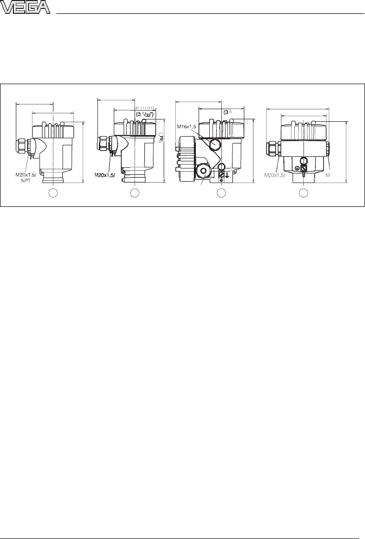
Accuracy see diagram
1,0 m 70 m
30 mm
15 mm
-15 mm
-30 mm
Fig.31:Accuracy VEGAPULS 68
Ambient conditions
Ambient,storage and transport temperature
-without PLICSCOM -40 ... +80°C(-40 ... +176°F)
-with PLICSCOM -20 ... +70°C(-4... +158°F)
54 VEGAPULS 68 -4... 20 mA/HART
Supplement
29261-EN-050202

Process conditions
Vessel pressure horn antenna
-without swivelling holder -1... 40 bar (-100 ... 4000 kPaor-14.5...
580)
-with swivelling holder -1... 1bar (-100 ... 100 kPaor-14.5...
14.5psi)not sealing
vessel pressure parabolic antenna
-without swivelling holder -1... 6bar (-100 ... 4000 kPaor-14.5... 87
psi)
-with swivelling holder -1... 1bar (-100 ... 100 kPaor-14.5...
14.5psi)not sealing
Process temperature (measured on the process fitting)depending on the seal of
the antenna system
-Viton -40 ... +130°C(-40 ... +266°F)
-Viton with temperature adapter -40 ... +200°C(-40 ... +392°F)
-Kalrez 2035,6230,6623 -15 ... +130°C(-5... +266°F)
-Kalrez 2035,6230 with tempe-
rature adapter
-15 ... +200°C(-5... +392°F)
-Kalrez 6375 -20 ... +130°C(-4... +266°F)
-Kalrez 6375 with temperature
adapter
-20 ... +200°C(-4... +392°F)
Vibration resistance mechanical vibrations with 4g and 5...
100 Hz4)
Data on rinsing air connection
Pressure max.6bar (87 psi)
Thread G⅛A
Check valve (option,attached with Ex version)
-Material 316Ti(stainless steel 1.4571)
-Seal Viton
-for tube diameter 6mm
-opening pressure 0.5bar (7.3psi)
-nominal pressure stage PN 250
4)Tested acc.to the regulations of German Lloyd,GL directive 2
VEGAPULS 68 -4... 20 mA/HART 55
Supplement
29261-EN-050202

Electromechanical data
Cable entry/plug5)
-single chamber housing l1x cable entry M20x1.5(cable-ø
5…9mm), 1x blind stopper M20x1.5
or:
l1x closing cap ½NPT,1xblind
stopper ½NPT
or:
l1xplug(depending on the version), 1x
blind stopper M20x1.5
-double chamber housing l1x cable entry M20x1.5(cable-ø
5…9mm), 1x blind stopper M20x1.5,
plug M12x1for VEGADIS 61 (option)
or:
l1x closing cap ½NPT,1x blind stopper
½NPT,plug M12x1for VEGADIS 61
(option)
or:
l1xplug(depending on the version), 1x
blind stopper M20x1.5,plug M12x1for
VEGADIS 61 (option)
Spring-loaded terminals for wire cross sections up to 2.5mm²
Indicating and adjustment module PLICSCOM
Power supply and data transmis-
sion
through sensor via gold-plated sliding
contacts (I²Cbus)
Indication LC display in dot matrix
Adjustment elements 4keys
Protection
-unassembled IP 20
-mounted into the sensor without
cover
IP 40
5)depending on the version M12x1,acc.to DIN 43650,Harting,
Amphenol-Tuchel,7/8"FF
56 VEGAPULS 68 -4... 20 mA/HART
Supplement
29261-EN-050202
Materials
-housing ABS
-inspection window Polyester foil
Power supply
Supply voltage
-non-Ex instrument 15 ... 36 VDC(14 ... 36 Vwith VEGAMET)
-EEx ia instrument 15 ... 30 VDC(14 ... 30 Vwith VEGAMET)
-EExd ia instrument 20 ... 36 VDC
Permissible residual ripple
-<100 HzU
ss
<1V
-100 Hz... 10 kHzU
ss
<10 mV
Load see diagram
1000
750
500
250
15 1816 20 22 24 26 28 30 32 34 36
Ω
V
4
12
3
Fig.32:Voltage diagram
1HART load
2Voltage limit EEx ia instrument
3Voltage limit non-Ex instrument/Exd instrument
4Supply voltage
Electrical protective measures
Protection IP 66/IP 67
Overvoltage category III
Protection class II
VEGAPULS 68 -4... 20 mA/HART 57
Supplement
29261-EN-050202

Approvals6)7)
ATEX ATEX II 1G,1/2G,2GEExiaIIC T5;ATEX
II 1/2G,2GEExdiaIIC T5;ATEX II 1/2D
IP6XT
IEC IEC EExiaIIC T5
6)Deviating data with Ex applications:see separate safety instru-
ctions
7)depending on order specification
58 VEGAPULS 68 -4... 20 mA/HART
Supplement
29261-EN-050202
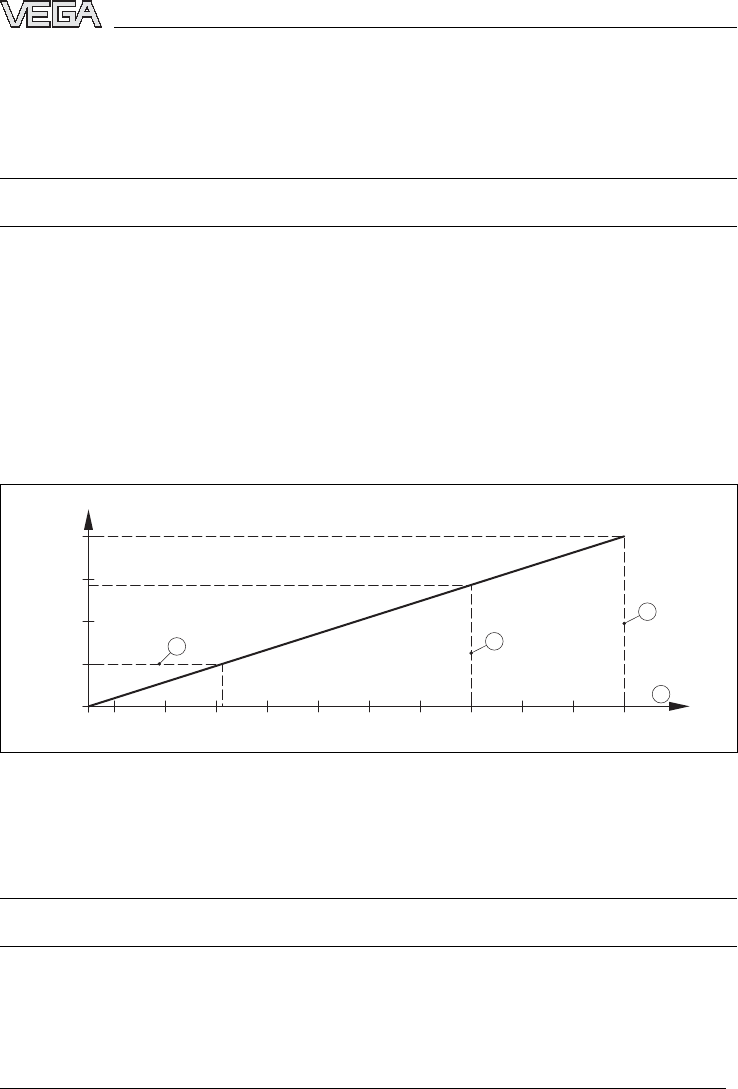
10.2Dimensions
Housing
1
12mm
(
4
13
/
32")
1
17mm
(
4
39
1
14mm
(
4 31/64")
1
20mm
(
4
23
/32")
~ 69mm
(2 23/32") ø 77mm
(3 1/32")
~ 69mm
(2 23/32") ~ 116mm (4 9/16")
~ 87mm (3 27/64")
ø
77mm
ø 84mm (3 5/16")
ø
84mm
/16")
2
0x1
,5
½
½
NPT
½
NPT
M20x1
,
5
/
½
NPT
1
2
3
4
Fig.33:Housing versions (with integrated PLICSCOM the height of the housing increases by 9mm/0.35 in)
1Plastic housing
2Stainless steel housing
3Aluminium double chamber housing
4Aluminium housing
VEGAPULS 68 -4... 20 mA/HART 59
Supplement
29261-EN-050202
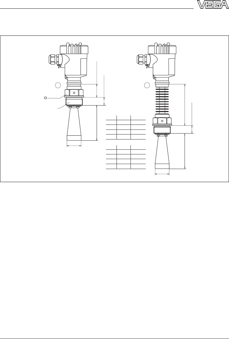
VEGAPULS 68 with horn antenna in threaded version
mm
inch
38mm (1 1/2")
22mm (55/64")
22mm (55/64")
118mm (4 41/64")
46mm
(1 13/16")
3 15/16"ø1
37/64"
ø1 57/64"
ø2 61/64"
ø3 47/64"
4 23/32"
8 1/2"
16 59/64"
xy
100 ø40
120 ø48
216 ø75
430 ø95
1½"
2"
3"
4"
xy
1½"
2"
3"
4"
x
y
G1½A / 1½ NPT
x
y
21
Fig.34:VEGAPULS 68 with horn antenna in threaded version
1Standard
2with temperature adapter
60 VEGAPULS 68 -4... 20 mA/HART
Supplement
29261-EN-050202
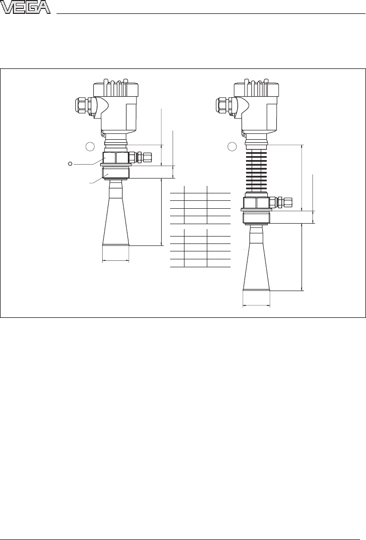
VEGAPULS 68 with horn antenna in threaded version with purging air
connection
mm
inch
38mm (1 1/2")
22mm (55/64")
22mm (55/64")
118mm (4 41/64")
3 15/16"
4 23/32"
8 1/2"
16 59/64"
ø1 37/64"
ø1 57/64"
ø2 61/64"
ø3 47/64"
46mm
(1 13/16")
x
y
G1½A / 1½ NPT
xy
100 ø40
120 ø48
216 ø75
430 ø95
1½"
2"
3"
4"
xy
1½"
2"
3"
4"
x
y
21
Fig.35:VEGAPULS 68 with horn antenna in threaded version with purging air connection and reflux valve
(option)
1Standard
2with temperature adapter
VEGAPULS 68 -4... 20 mA/HART 61
Supplement
29261-EN-050202
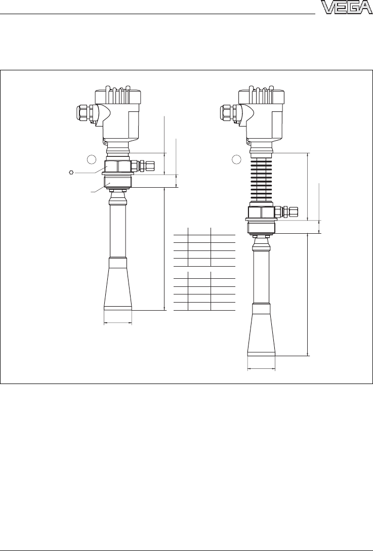
VEGAPULS 68 with horn antenna in threaded version with purging air
connection and antenna extension
mm
inch
38mm (1 1/2")
22mm (55/64")
22mm (55/64")
118mm (4 41/64")
7 3/32"ø1
37/64"
ø1 57/64"
ø2 61/64"
ø3 47/64"
7 7/8"
11 21/32"
24 51/64"
46mm
(1 13/16")
x
y
G1½A / 1½ NPT
xy
> 180 ø40
> 200 ø48
> 296 ø75
> 630 ø95
1½"
2"
3"
4"
xy
1½"
2"
3"
4"
x
y
21
Fig.36:VEGAPULS 68 with horn antenna in threaded version with purging air connection,antenna
extension and reflux valve (option)
1Standard
2with temperature adapter
62 VEGAPULS 68 -4... 20 mA/HART
Supplement
29261-EN-050202
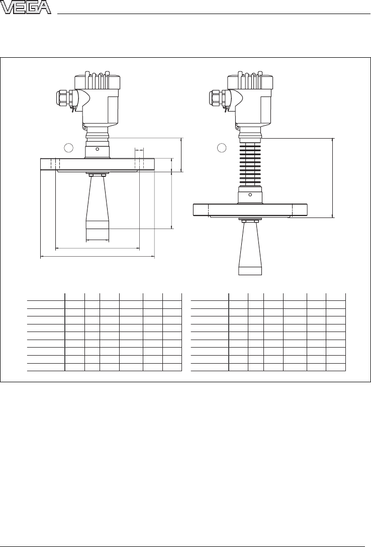
VEGAPULS 68 with horn antenna in flange version
60mm
(2 23/64")
140mm (5 33/64")
4xø3/4"
4xø3/4"
8xø55/64"
8xø3/4"
8xø7/8"
4xø45/64"
8xø45/64"
8xø45/64"
4 3/4"
4 59/64"
6 19/64"2
61/64"
3 47/64"
3 47/64"
16 59/64"
16 59/64"
1 57/64"4
23/32"
8 1/2"
1 37/64"
1 57/64"4
23/32"
3 15/16"
2 61/64"
3 47/64"
3 47/64"
16 59/64"
16 59/64"
8 1/2"
7 3/32"
9 29/64"
25/32"
25/32"
55/64"
15/16"
3/4"
15/16"
15/16"
6 1/2"
4xø45/64"4 21/64"
45/64"5 29/32"
7 7/8"
8 21/32"
11 7/32"
7 1/2"
7 1/2"
9 1/2"
6"
6"
9"
11" 1"
D
mm
bk dx
DN 50 PN 40 165 20 125 4xø18
DN 80 PN 40 200 24 160 8xø18
DN 100 PN 16 220 20 180 8xø18
DN 150 PN 16 285 22 240 8xø22
2" 150 lb 152,4 19,1 120,7 4xø19,1
3" 150 lb 190,5 23,9 152,4 4xø19,1
4" 150 lb 228,6 23,9 190,5 8xø19,1
6" 150 lb 279,4 25,4 241,3 8xø22,4
y
48 120
75 216
95 430
95 430
48 120
xy
75 216
95 430
95 430
D
inch
bk d
DN 50 PN 40
DN 40 PN 40 150 18 110 4xø18 40 100 DN 40PN 40
DN 80 PN 40
DN 100 PN 16
DN 150 PN 16
2" 150 lb
3" 150 lb
4" 150 lb
6" 150 lb
D
k
x
d
b
y
21
Fig.37:VEGAPULS 68 with horn antenna in flange version
1Standard
2with temperature adapter
VEGAPULS 68 -4... 20 mA/HART 63
Supplement
29261-EN-050202
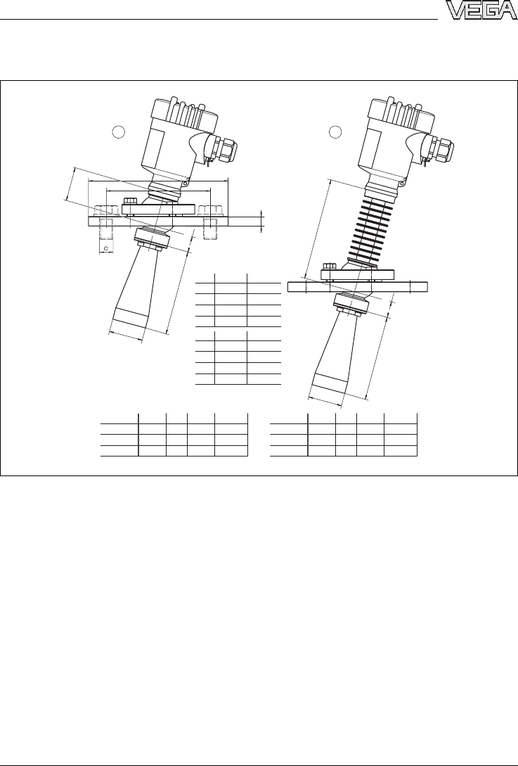
VEGAPULS 68 with horn antenna and swivelling holder
mm
inch
D
mm
bk d
DN 50 / 2" 165 11,5 122,8 4xø19
DN 80 / 3" 200 11,5 156,2 4xø21
DN 100 / 4" 220 11,5 182,5 4xø22
D
inch
bk d
DN 50 / 2"
DN 80 / 3"
DN 100 / 4"
120mm (4 23/32")
20mm
(25/32")
20mm
(25/32")
6 1/2"4
53/64"4xø
3/4"
4xø53/64"
8xø55/64"
6 5/32"
7 3/16"
29/64"
29/64"
29/64"
7 7/8"
8 21/32"
3 15/16" ø1 37/64"
ø1 57/64"
ø2 61/64"
ø3 47/64"
4 23/32"
8 1/2"
16 59/64"
b
D
k
x
y
x
y
21
xy
100 ø40
120 ø48
216 ø75
430 ø95
1½"
2"
3"
4"
xy
1½"
2"
3"
4"
40mm
(1 37/64")
Fig.38:VEGAPULS 68 with horn antenna and swivelling holder
1Standard
2with temperature adapter
64 VEGAPULS 68 -4... 20 mA/HART
Supplement
29261-EN-050202
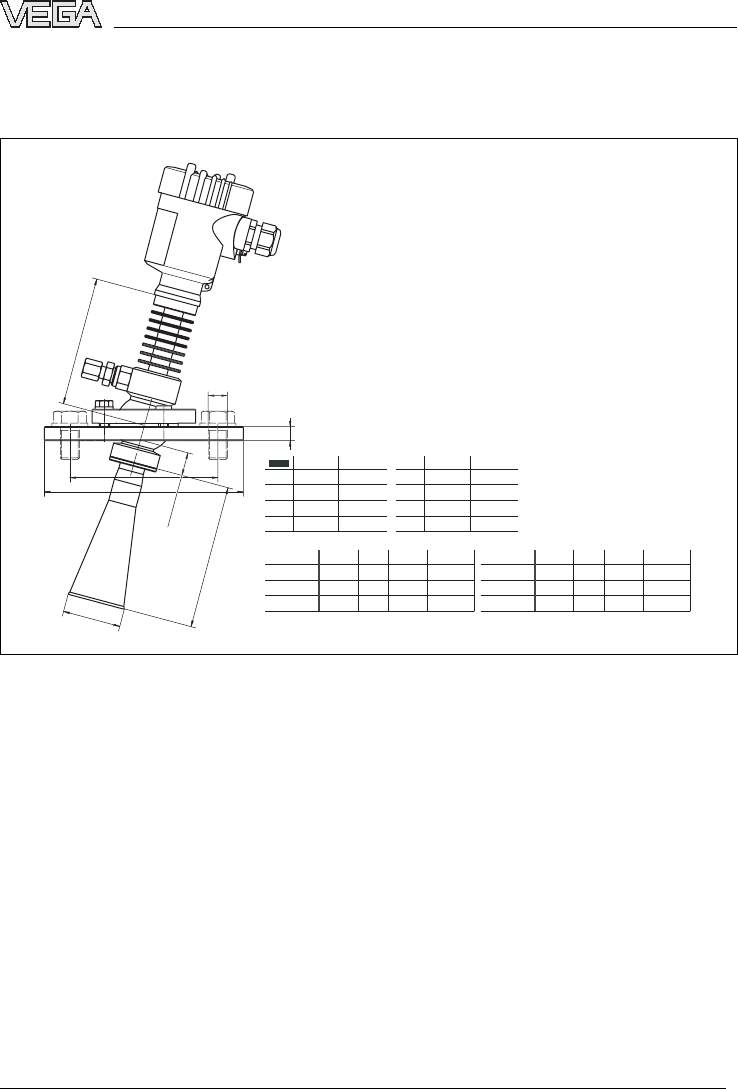
VEGAPULS 68 with horn antenna,swivelling holder and purging air
connection
D
mm
bk d
DN 50 / 2" 165 11,5 122,8 4xø19
DN 80 / 3" 200 11,5 156,2 4xø21
DN 100 / 4" 220 11,5 182,5 4xø22
D
inch
bk d
DN 50 / 2"
DN 80 / 3"
DN 100 / 4"
inch
8 1/2"
16 59/64"
3 15/16"ø1
37/64"
ø1 57/64"
ø2 61/64"
ø3 47/64"
4 23/34"
216
430
xy
100 ø40
120 ø48
ø75
ø95
1½"
2"
3"
4"
xy
1½"
2"
3"
4"
6 1/2"4
53/64"4xø
3/4"
4xø53/64"
8xø55/64"
6 5/32"
7 3/16"
29/64"
29/64"
29/64"
7 7/8"
8 21/32"
120mm (4 23/32")
20mm
(25/32")
d
b
D
k
x
y
Fig.39:VEGAPULS 68 with horn antenna,swivelling holder,purging air connection and reflux valve
(option)
VEGAPULS 68 -4... 20 mA/HART 65
Supplement
29261-EN-050202
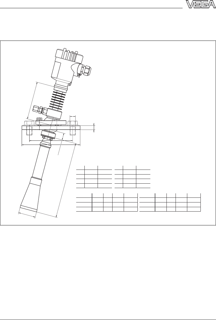
VEGAPULS 68 with horn antenna,swivelling holder,purging air connection
and antenna extension
mm inch
D
mm
bk d
DN 50 / 2" 165 11,5 122,8 4xø19
DN 80 / 3" 200 11,5 156,2 4xø21
DN 100 / 4" 220 11,5 182,5 4xø22
D
inch
bk d
DN 50 / 2"
DN 80 / 3"
DN 100 / 4"
6 1/2"4
53/64"4xø
3/4"
4xø53/64"
8xø55/64"
6 5/32"
7 3/16"
29/64"
29/64"
29/64"
7 7/8"
8 21/32"
120mm (4 23/32")
20mm
(25/32")
7 3/32"ø1
37/64"
ø1 57/64"
ø2 61/64"
ø3 47/64"
7 7/8"
11 21/32"
24 51/64"
d
xy
> 180 ø40
> 200 ø48
> 296 ø75
> 630 ø95
1½"
2"
3"
4"
xy
1½"
2"
3"
4"
b
D
k
x
y
Fig.40:VEGAPULS 68 with horn antenna,swivelling holder,purging air connection,antenna extension
and reflux valve (option)
66 VEGAPULS 68 -4... 20 mA/HART
Supplement
29261-EN-050202

VEGAPULS 68 with parabolic antenna in threaded version
38mm (1 1/2")
22mm (55/64")
22mm (55/64")
118mm (4 41/64")
128mm
(5 3/64")
ø 243mm (9 9/16")
46mm
(1 13/16")
G1½A / 1½ NPT
21
Fig.41:VEGAPULS 68 with parabolic antenna in threaded version
1Standard
2with temperature adapter
VEGAPULS 68 -4... 20 mA/HART 67
Supplement
29261-EN-050202
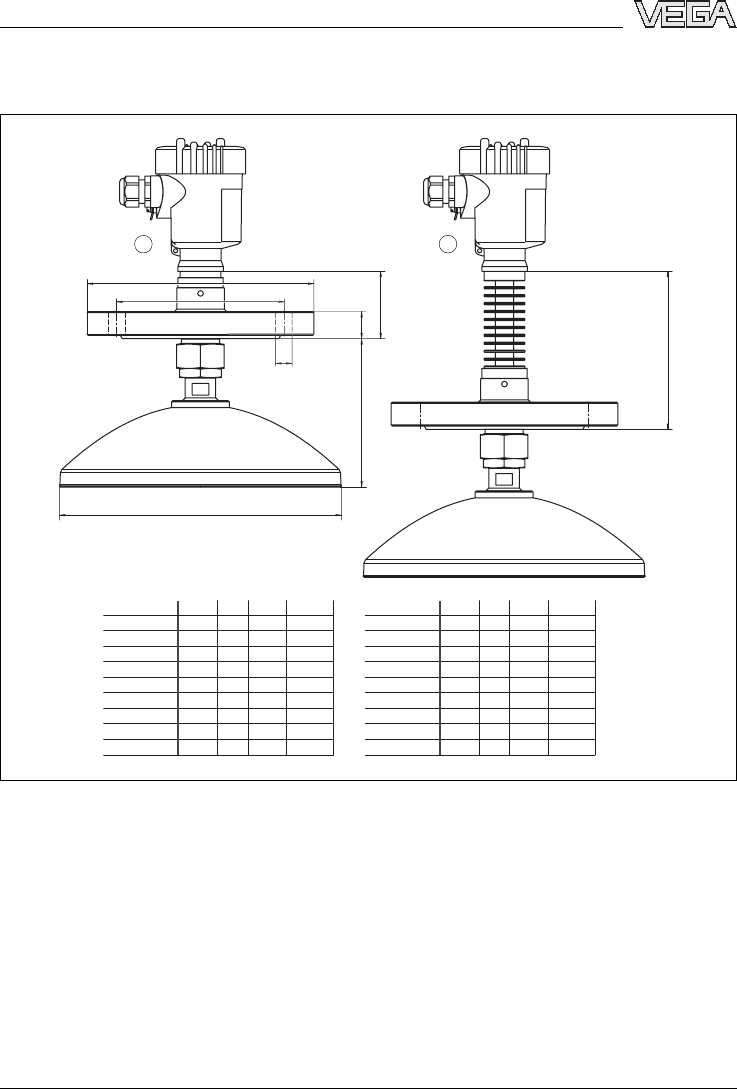
VEGAPULS 68 with parabolic antenna in flange version
D
mm
bk d
DN 50 PN 40 165 20 125 4xø18
DN 80 PN 40 200 24 160 8xø18
DN 100 PN 16 220 20 180 8xø18
DN 150 PN 16 285 22 240 8xø22
2" 150 lb 152,4 19,1 120,7 4xø19,1
3" 150 lb 190,5 23,9 152,4 4xø19,1
4" 150 lb 228,6 23,9 190,5 8xø19,1
6" 150 lb 279,4 25,4 241,3 8xø22,4
D
inch
bk d
DN 50 PN 40
DN 40 PN 40 150 18 110 4xø18 DN 40PN 40
DN 80 PN 40
DN 100 PN 16
DN 150 PN 16
2" 150 lb
3" 150 lb
4" 150 lb
6" 150 lb
21
D
k
b
60mm
(2 23/64")
128mm
(5 3/64")
140mm (5 33/64")
4xø3/4"
4xø3/4"
8xø55/64"
8xø3/4"
8xø7/8"
4xø45/64"
8xø45/64"
8xø45/64"
4 3/4"
4 59/64"
6 19/64"
7 3/32"
9 29/64"
25/32"
25/32"
55/64"
15/16"
3/4"
15/16"
15/16"
6 1/2"
4xø45/64"4 21/64"
45/64"5 29/32"
7 7/8"
8 21/32"
11 7/32"
7 1/2"
7 1/2"
9 1/2"
6"
6"
9"
11" 1"
d
ø 243mm (9 9/16")
Fig.42:VEGAPULS 68 with parabolic antenna in flange version
1Standard
2with temperature adapter
68 VEGAPULS 68 -4... 20 mA/HART
Supplement
29261-EN-050202
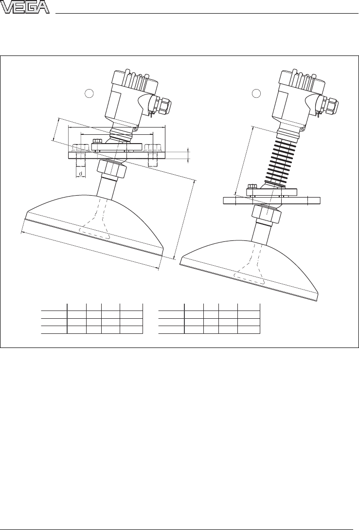
VEGAPULS 68 with parabolic antenna and swivelling holder
D
mm
bk d
DN 50 / 2" 165 11,5 122,8 4xø19
DN 80 / 3" 200 11,5 156,2 4xø21
DN 100 / 4" 220 11,5 182,5 4xø22
D
inch
bk d
DN 50 / 2"
DN 80 / 3"
DN 100 / 4"
6 1/2"4
53/64"4xø
3/4"
4xø53/64"
8xø55/64"
6 5/32"
7 3/16"
29/64"
29/64"
29/64"
7 7/8"
8 21/32"
120mm (4 23/32")
140mm (5 33/64")
ø 243mm (9 9/16")
b
D
k
21
40mm
(1 37/64")
Fig.43:VEGAPULS 68 with parabolic antenna and swivelling holder
1Standard
2with temperature adapter
VEGAPULS 68 -4... 20 mA/HART 69
Supplement
29261-EN-050202
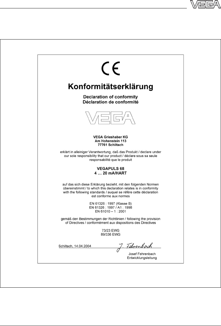
10.3CE declaration of conformity
Fig.44:CE declaration of conformity
70 VEGAPULS 68 -4... 20 mA/HART
29261-EN-050202

VEGAPULS 68 -4... 20 mA/HART 71
29261-EN-050202

VEGA Grieshaber KG
AmHohenstein 113
77761 Schiltach
Germany
Phone +49 7836 50-0
Fax +49 7836 50-201
E-mail:info@de.vega.com
www.vega.com
ISO 9001
All statements concerning scope of delivery,application,
practical use and operating conditions of the sensors and
processing systems correspond to the information avail-
able at the time of printing.
Technical data subject to alterations 29261-EN-050202