VTech Telecommunications 80-4282-00 User Manual USER GUIDE
VTech Telecommunications Ltd USER GUIDE
Contents
- 1. USER GUIDE
- 2. USERS GUIDE
USER GUIDE
VTECH ENGINEERING CANADA LIMITED
TITLE Electrical Specification
MODEL SPP-ID970/1,ID975/6,A973/4
Reference: 00F2 Revision: 2.0 Page: 1 of 8
This document is proprietary to VTECH ENGINEERING CANADA LTD. 28711
Specifications are preliminary and are subject to change without notice.
SPP-ID970/1,975/6
SPP-A973/4
Electrical Specification
Document ID: CPX94-1L
Note: All rights reserved. No part of this publication may be reproduced or transmitted in any form or by
any means. The only controlled copy of this document is kept in electronic form on the VTECH computer
network. All printed copies are uncontrolled documents and are not updated. This Procedure is the
property of VTECH Engineering Canada Ltd., and shall be returned upon request
.
Prepared By Guy Pothiboon
Title Project Manager
Approved By
Title
VTECH ENGINEERING CANADA LIMITED
TITLE Electrical Specification
MODEL SPP-ID970/1,ID975/6,A973/4
Reference: 00F2 Revision: 2.0 Page: 2 of 8
This document is proprietary to VTECH ENGINEERING CANADA LTD. 28711
Specifications are preliminary and are subject to change without notice.
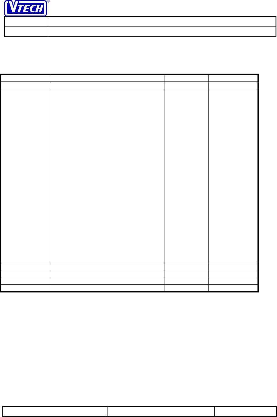
Revision History
Revision No Description Page Effective Date
1.0 First Release All Jan 25,’99
2.0 • Changed Model numbers to reflect
the Official Product Numbers from
SONY
• Changed DC Electrical
Characteristics
• Base Standby Time Max TBD to
Min 7
• Base Continuous Talk Time Max
TBD to Min 7
• Changed Audio Specification
• Receive Volume to provide
typical rating of 12 instead of
Minimum rating of 12
• Changed RF Parameters
• Image Rejection from 60 to 55
• Receiver Muting –107 to –106
• Added RF parameters
• Channel Spacing
• Radiated Field Strength
• Receive Frequency
• Transmit Frequency Stability
• Sensitivity
• 3
rd Order Intercept Point
• Adjacent Channel Rejection
• Aggregate Data Rate
Title Page
and Headers
3
3
6
Feb 19,’99
VTECH ENGINEERING CANADA LIMITED
TITLE Electrical Specification
MODEL SPP-ID970/1,ID975/6,A973/4
Reference: 00F2 Revision: 2.0 Page: 3 of 8
This document is proprietary to VTECH ENGINEERING CANADA LTD. 28711
Specifications are preliminary and are subject to change without notice.
VTECH ENGINEERING CANADA LIMITED
TITLE Electrical Specification
MODEL SPP-ID970/1,ID975/6,A973/4
Reference: 00F2 Revision: 2.0 Page: 4 of 8
This document is proprietary to VTECH ENGINEERING CANADA LTD. 28711
Specifications are preliminary and are subject to change without notice.
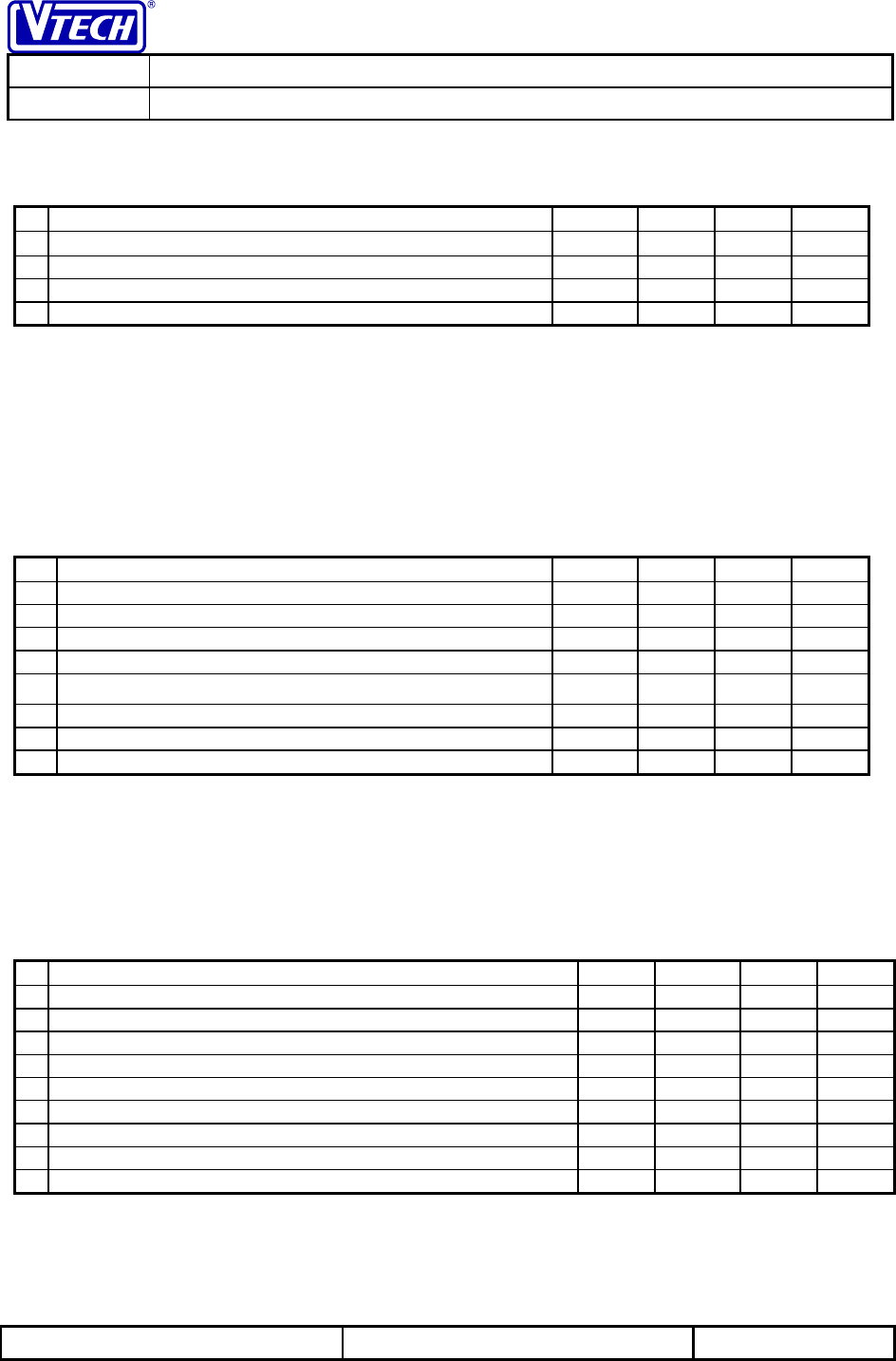
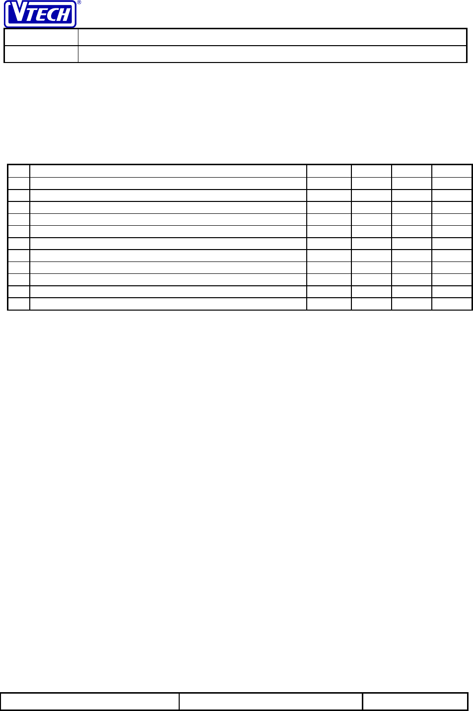
Electrical Specifications
1.1 Operating Conditions
Parameter Min Typ Max Units
Operating Temperature Range 0 251402°C
Base Unit Operating Voltage (AC Voltage, 60Hz) 96 1201144 Vrms
Base Unit Operating Voltage (AC Adapter Output) 91Vdc
Handset Operating Voltage23.2 3.61,3 4.2 Vdc
Notes:
1. Typical value represents the nominal testing value
2. NiCd Battery should not be operated above 40 °C.
3. Handset operates from a 3-cell NiCd Battery.
1.2 DC Electrical Characteristics
Specifications marked with * are guaranteed at the nominal testing temperature and voltage on all units
with the use of automated production test equipment (ATE)
Parameter Min Typ Max Units
* Low Battery Detection Threshold (HS) 3.5 Vdc
Handset Standby Time 7 Days
Handset Continuous Talk Time 7 Hours
Base Unit Standby Time – POTS Mode TBD Hours
Base Unit Continuous Talk Time – POTS Mode TBD Hours
Fast Charge – Handset Battery 120 mA
Slow Charge – Handset Battery 60 mA
Spare Battery Charge 30 mA
1.3 Audio Specification
Specifications marked with * are guaranteed at the nominal testing temperature and voltage on all units
with the use of automated production test equipment (ATE).
Parameter Min Typ Max Units
* Transmit Objective Loudness Rating (TOLR)1-40 -46 -53 dB
* Receive Objective Loudness Rating (ROLR)1,2 51 +46 41 dB
* Sidetone Objective Loudness Rating (SOLR)3+3 +8 +19 dB
* Receive volume adjustment range 12 TBD TBD dB
* Transmit Direction Acoustic Overload (into microphone)4105 dBspl
* Receive Direction Acoustic Overload (from receiver)4105 dBspl
Transmit Direction Noise520 dBrnC
Receive Direction Noise2,5 40 dB(A)
Peak Acoustic Pressure6130 dBspl
Notes:
1. Tested using 0kft of simulated telephone line
2. Tested at normal (low) volume level
3. Base unit connected to 0kft of simulated telephone line terminated with 900Ω
4. Acoustic level that results in 5% THD, measured at 1kHz through a 5kHz lowpass filter
VTECH ENGINEERING CANADA LIMITED
TITLE Electrical Specification
MODEL SPP-ID970/1,ID975/6,A973/4
Reference: 00F2 Revision: 2.0 Page: 5 of 8
This document is proprietary to VTECH ENGINEERING CANADA LTD. 28711
Specifications are preliminary and are subject to change without notice.
5. Handset isolated from sound input and mechanical disturbances
6. Tested at high volume level
1.4 Telephone Line Interface Specification
Specifications marked with * are guaranteed at the nominal testing temperature and voltage on all units
with the use of automated production test equipment (ATE).
Parameter Min Typ Max Units
* DTMF Frequency Tolerance -1.5 +1.5 %
* DTMF Low Group Tone Level1-7.5 -5.0 -4.0 dBm
* DTMF High Group Tone Level1-5.5 -3.0 -2.0 dBm
DTMF Combined Tone Level1+2.0 dBm
DTMF High Group Pre-emphasis (Twist) 2.0 4.0 dB
Pulse Dialing Break Duration 60 ms
Pulse Dialing Make Duration 40 ms
Pulse Dialing Rate 10 pps
Ring Detection Frequency2,3 15 68 Hz
Ring Response Voltage340 Vrms
Ring No-Response Voltage425 Vrms
Notes:
The above specification are derived from the TIA/EIA-470-B publication
1. Measured across a 900Ω terminating impedance
2. The ringer must ring with signals within this range
3. Measured with a frequency of 20Hz
4. The ringer must not ring with signals within this range
VTECH ENGINEERING CANADA LIMITED
TITLE Electrical Specification
MODEL SPP-ID970/1,ID975/6,A973/4
Reference: 00F2 Revision: 2.0 Page: 6 of 8
This document is proprietary to VTECH ENGINEERING CANADA LTD. 28711
Specifications are preliminary and are subject to change without notice.
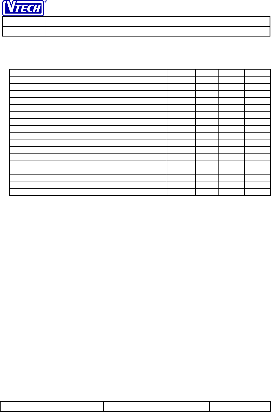
1.5 Calling Line Identification Specification
Parameter Min Typ Max Units
Receive Space Frequency 2178 2200 2222 Hz
Receive Mark Frequency 1188 1200 1212 Hz
Receive Baud Rate 1188 1200 1212 Baud
Mark FSK Detector Sensitivity -32 -12 dBm
Space FSK Detector Sensitivity -36 -32 dBm
FSK Detector Twist -10 +10 dB
CAS Detection Sensitivity -32 dBm
Channel Seizure Delays 300 Bits
Immunity to Stuffed Mark Bits 360 Bits
CAS
Frequency limits Lower Tone 2023.5 2130 2236.5 Hz
Upper Tone 2612.5 2130 2887.5 Hz
Dynamic Range (per tone) -32 -14 dBm
Twist < 6 dB
Tone Duration 75 85 mS
ACK
Signal Duration 55 65 mS
Notes: The above specification have been derived from the following Bellcore standards
• Bellcore TR-NWT-000030 Issue 2
"Voiceband Data Transmission Interface Generic Requirements"
• Bellcore TR-NWT-000031 Issue 4
"CLASS Feature: Calling Number Delivery"
• Bellcore TR-NWT-001188 Issue 1
"CLASS Feature: Calling Name Delivery Generic Requirements"
VTECH ENGINEERING CANADA LIMITED
TITLE Electrical Specification
MODEL SPP-ID970/1,ID975/6,A973/4
Reference: 00F2 Revision: 2.0 Page: 7 of 8
This document is proprietary to VTECH ENGINEERING CANADA LTD. 28711
Specifications are preliminary and are subject to change without notice.
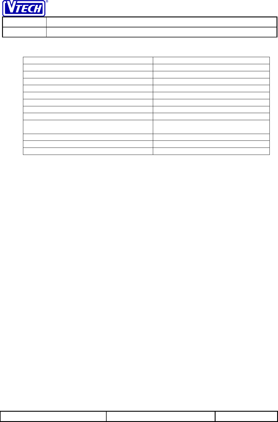
1.6 Radio Specification
Number of RF Channels 30
Handset Transmission Frequency Range 923.1 – 927.75 MHz
Base Transmission Frequency Range 902.3 –906.65 MHz
Channel Spacing 300 KHz
Image Rejection (RF) > 55 dB
Receiver Muting Level Between -109 dBm and -106 dBm
RF Radiated Field Strength < 94 dBuV/m @ 3 meters
Receive Frequency 10.7 MHz
Transmit Frequency Stability +/-10 KHz, 0 to 50c
Sensitivity for 1/1000 bit errors Less than or equal to -105 dBm @
antenna
3rd Order Intercept Point > 55 dB
Adjacent Channel Rejection > 50 dB
Aggregate Data Rate 48 Kbps
Note: For spurious rejection measurements, RF level of the desired signal is set to provide 25dB SINAD (CCITT). The
rejection is the relative level of the interference signal above the desired to reduce the SINAD to 20dB (CCITT)

VTECH ENGINEERING CANADA LIMITED
TITLE Electrical Specification
MODEL SPP-ID970/1,ID975/6,A973/4
Reference: 00F2 Revision: 2.0 Page: 8 of 8
This document is proprietary to VTECH ENGINEERING CANADA LTD. 28711
Specifications are preliminary and are subject to change without notice.
1.7 Regulatory Specifications
• The circuit must meet the radio frequency emission requirements defined in FCC regulations Part 15
and IC RSS-210.
• The circuit must meet telephone interface requirements defined in FCC part 68 and IC CS-03
standards.