Venture Global HAXPFAT Multi-Functional Alarm Transmitter User Manual 2
Venture Global Limited Multi-Functional Alarm Transmitter 2
Manual

FCC Statement:
This equipment has been tested and found to comply with the limits for a Class B digital device, pursuant to part 15 of the FCC Rules. These limits are designed to provide reasonable protection against harmful interference in
a residential installation. This equipment generates, uses and can radiate radio frequency energy and, if not installed and used in accordance with the instructions, may cause harmful interference to radio communications.
However, there is no guarantee that interference will not occur in a particular installation. If this equipment does cause harmful interference to radio or television reception, which can be determined by turning the equipment off
and on, the user is encouraged to try to correct the interference by one or more of the following measures:
Reorient or relocate the receiving antenna.
Increase the separation between the equipment and receiver.
Connect the equipment to an outlet on a circuit different from that to which the receiver is connected.
This device complies with part 15 of the FCC rules. Operation is subject to the following two conditions: (1) This device may not cause harmful interference, and (2) this device must accept any interference received, including
interference that may cause undesired operation.
Note: Modifications to this product will void the user's authority to operate this equipment.
R
Mode
Mat
Pad
+3S
II
I
R
Mode
Mat
Pad
+3S
II
I
R
Mode
Mat
Pad
+3S
II
I
USER MANUAL HAX-300-500
PWR
TX
SND
LIGHT
On
Off
On
Off
ReCode
A
On
Off
B
Mode Sound
Hi
Lo
Off
NO
NC
3S
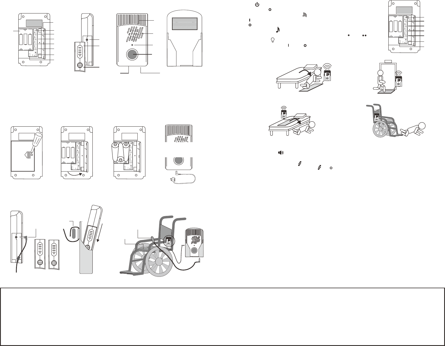
Parts and Function
1
2
10
11
13
14
15
16
12
17 18
3
4
5
6
7
8
9
1. Batteries compartment
2. Battery Door
3. Regenerates new code button.
4. Power on/off switch
5. Transmitter On/off switch.
6. Alert sound selector.
Power
+
Remove the screw
and slide to open
the battery cover
Flip to open the cover Insert 3 AAA bateries to
the battery compartment
and close the battery cover
AAA
AAA
AAA
Setting
7. Light on/off switch.
8. Volume control.
9. Mode control.
10. Sensor input jack
11. Anti-take off Cover
12 Cover lock
Installation
Nurse Call Button
Chair Pad
Chair Pad
plug
Unlock lock
Unlock and slide out the
cover to install the plug
Slide the switches inside the battery cover for your needs.
1. Power
Switch to off position when do not use this device.
2. Transmitter On/Off switch
On : Send a trigger signal to receiver when triggered
Off : Do not send signal to receiver when triggered.
3. Sound selector
Select the suitable sound by slide this switch to or position..
4. Light On/Off
Turn the flash light on or off by slide this switch.
5. Mode
Mat (Fall mat): This mode for fall mat or entry mat. The unit triggered when someone
step on the mat.
Pad (Bed Pad): This mode for seat pad or bed pad. The unit triggered when Patients or
elderly leave the pad.
Pad +3S (Pad & 3 seconds delay): Same as Pad mode but delay 3 seconds for reduce False
alarms.
6. Volume control
You can select High II / Low I / No sound by slide this switch.
7 Regenerate a new code
If the RF code is conflict, press the button in the pin hole to regenerate a new code
13 Flasher
14. Speaker
15 LED indicator.
16. Test /Reset button
17. External DC jack
18. Nurse call button jack.
1
2
3
4
5
6
7
EXIT
Pairing with receiver
Operation
This unit can work stand alone or work with the wireless receiver. If work with the receiver, you
need to pairing with the receiver follow to the manual of the receiver.
Velcro
Mat mode
The sensor unit will be triggered when someone step on the mat.
Pad mode
when the person lying (sitting) on the sensor pad. The sensor unit will generate a beep tone to
confirm the pad is function. The unit will be triggered when Patients or elderly leave the pad
sensor. Alarm will stop when the person return to the pad or press the stop button.
Delay Mode
Functions are same as Pad mode, but delay 3 seconds after triggered for reduce False alarms.
Nurse call
Press the nurse button once (the big nurse call button must be plug in), the sensor unit will be
send a trigger signal to receiver, and sensor unit will generate beep tone to indicate this button is
pressed.
R
R
R
Mode
Mat
Pad
+3S
II
I
Test & Reset
- Test: Press the test/Reset button once, The unit will generate a beep tone, LED will blink
and will send a RF to the receiver (It will depend on the function switch setting)
- Reset: When the alarm is triggered, press the test/Reset thrice within 2 seconds will stop
Or Using a 5V/ 300mA
AC/DC adaptor
5V AC/DC adaptor
(Switching mode)