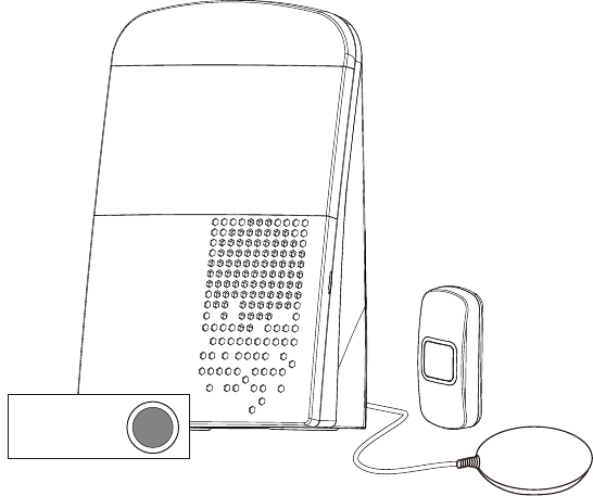
Venture Global MA3000 Multi-Alert Receiver User Manual MANUAL
Venture Global Limited Multi-Alert Receiver MANUAL
User Manual

USER MANUAL
Multi-Alert System
With
Dual Alarm Clock
MA-3000Ck

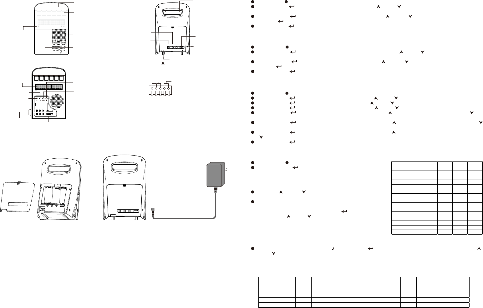
Parts and Function
Setting
Batt . Low
Icon Pate
(replaceable)
LED
Dispaly
Speaker
Alarm Indicator
AC power
indicator
Cover
On
Off
3S
15S
On
Off
On
Off
On
Off
Auto
Manu
AL1 Timer Vi b
AL2 Lig ht Dim mer
Tone
Volume
Mode/Setting
Button
Confirm Button
Down Botton
Up Botton
Beep Sound Tone
Function On/Off
Switch
Volume Control
Flasher
Ext.
Trigg er
Alar m
Out 5V Out
Vib
Out
12V
DC In
Dimm erCale ndar
Snoo ze/St op
DC 12V In
Vibration Out
Alarm Audio
Out
External
Trigger In
USB
Charger (out)
Calendar
Snooze/Stop
Dimmer
12V Out &
NC/No Relay Out
Battery
Cover
NO NC +12V-
SETCalendar (Set Cal)
Press Mode button once, The display show Set Cal.
Press confirm button to set calendar year. Press Up / Down button adjust the year, the year "up to
2099
Press confirm button to set calendar month. Press Up / Down button adjust the month. Press
confirm button to set calendar date.
Press confirm button to finishing and exit the calendar setting.
SETClock (Set Ck)
The time display will blinking when install batteries and connect to ac power. Please adjust the clock to keep
the time is correct.
Press Mode button twice, The display show Set Ck.
Press confirm button to set time format 12 /24 hour. Press Up / Down button select the 12 or 24
hour format.
Press confirm button jump to set minute. Press Up / Down button adjust the minute. Press
confirm button to set hour. Press Up/ Down button adjust the Hour.
Press confirm button to finishing and exit the time setting mode.
*** Each time you press the confirm button, the time second will reset to zero. (The clock will run from
zero second after you set the clock.)
SETAlarm Time (Set A1 or A2)
Press Mode button three or four time, The display show Set A1 or A2.
Press confirm button to set alarm minute. Press Up / Down button to adjust the alarm minute.
Press confirm button to set alarm hour. Press Up / Down button to adjust the alarm hour.
Press confirm button to set alarm melody. Press Up / Down button to select the alarm melody.
Press confirm button to set vibration on or off. Press Up to turn on the vibrator. Press down to
turn off vibrator.
Press confirm button to set 12V output on or off. Press Up to turn on the 12V output. Press down
to turn off vibrator the 12V output.
Press confirm button to set relay output on or off. Press Up to turn on the relay output. Press down
to turn off vibrator the relay output.
Press confirm button to finishing and exit the time setting mode.
Please do not forget turn the alarm switch inside the front cover.
Matching (Pair)
Press Mode button five time, The display show Pair
Press confirm button to entering to pair mode. the
display show Zone: -1 or Zone:1
Zone 1 = Zone 1 is empty; Zone: 1 = Zone 1 is already
paired with the sensor, and if it continues, the new sensor
will replace the old one.
Press up or down button to select the zone you want to
pair.
Trigger the transmitter/sensor you want to pair. The display
will show linked when the pair is success. then the receiver
show the sensor name, Press confirm button to confirm
or press up /down button to select an other sensor
name.
If it do not show “linked” information, it show other zone
number when trigger the sensor. This sensor is already paired
in other zone.
Please ensures the sound volume is not on the min position before setting.
SENSOR NAME Defult Option Option
Door Bell Bell D. Bell Knock
Door/window Sensor Window Door Invade
Mailbox Sensor Mail M. Box Letter
Fall sensor Fall Al Pad Help
Flood detector Flood Empty Full
Toilet pull sensor Toilet Help Slip
Magnet sensor Magnet Steal Lost
Entry mat Mat Escape Enter
PIR/Driveway sensor PIR Road Invade
Sound sensor Baby Cry Sound
Telephone ring transmitter Phone Ring Call
Garage door Garage Open G.Door
Gas detector Gas Danger Alarm
T3 Smoke Danger Fire
T4 CO Danger Fire
Power
Battery Low
The receiver powered by a 12V 1.2A AC/DC adaptor and backup by 3 pieces ‘C’ size batteries.
Install the backup batteries avoid lost alert information when ac power fail. The AC power indicator
will lit when the ac power is good.
Ext.
Trigg er
Alar m
Out 5V O ut
Vib
Out
12V
DC In
Dimm erCale nda r
Snoo ze/ Sto p
12V/
1.2A
.
Receiver unit:
When the backup batteries are low voltage, the low battery information “BattLo” will show on the display for 1
second every 15 seconds. Replace the batteries as soon as possible.
Sensor unit
When the battery of the sensor/Bell pusher is low voltage. It will send a battery low information with the trigger
signal to the receiver. The receiver will blink the zone icon to indicate this sensor battery is low voltage. Replace
the battery as soon as possible.
** The display time will blink, when the AC power and the backup batteries are lost before. Press the reset
button to stop blinking. (The clock will run with the internal CR2032 battery. Power loss will not affect clock
accuracy)
** If ac power is fail, the USB charger, Vibration pad, and 12V output will not work.
The connect is Inside the
battery cover
Then display will show the melody . Press confirm button to confirm the default melody or press up /
down button to select an other melody. (each type of sensor have a default melody)
The melody number from 00 to 32, The #32 is a beep tone , you can adjust the tone lever to change the pitch
of the sound.
*** Select ‘None’ to mute this sensor
SENSOR NAME
Defult
Sound# SENSOR NAME
Defult
Sound# SENSOR NAME
Defult
Sound# SENSOR NAME
Defult
Sound#
Door Bell 1 Flood detector 14 PIR/Driveway sensor 13 Gas detector 10
Door/window Sensor 28 Toilet pull sensor 27 Sound sensor 31 T3 13
Mailbox Sensor 12 Magnet sensor 17 Phone Ring 19 T4 13
Fall sensor 29 Entry mat 15 Garage door 6
Open the battery cover
to install the batteries.
Connect the power adaptor
1 2
RECEIVER

On
Off
3S
15S
On
Off
On
Off
On
Off
Auto
Manu
AL1 Timer Vib
AL2 Light Dimmer
Tone
Volume
Show Calendar
Press the calendar button once, the display will show the calendar for 10 seconds.
Dimmer
Press the dimmer button to select the brightness of the display
Alarm 1 On/Off (clock alarm 1)
Slide the AL1 switch to on or off position. When Alarm 1 is on the alarm1 indicator will light up
Alarm 2 On/Off (clock alarm 2)
Slide the AL2 switch to on or off position. When Alarm 2 is on the alarm2 indicator will light up.
Timer
Slide the timer switch to select the duration of the relay output and 12V output .
Light On/Off
Slide the master light switch to on or off flasher light.
Vibrator On/Off
Slide the Vib master switch to turn on or off vibrator. This is a master switch.
Dimmer Mode
Auto: The LED display dims automatically in the dark .
Manual: Adjust the LED display brightness by pressing the dimmer button.
Tone Adjust
Slide the tone lever to adjust the tone of the beep
sound alert (Sound number 32).
Volume Control
Slide the volume to adjust master sound volume.
Other Setting
Outlet and inlet
DC Jack : Main power 12V 1A input.
Dim merCal end ar
Sno oze /St op
Press confirm button to set vibration on or off. Press Up to turn on the vibrator. Press down to turn off
vibrator.
Press confirm button to set 12V output on or off. Press Up to turn on the 12V output. Press down to turn off
vibrator the 12V output.
Press confirm button to set relay output on or off. Press Up to turn on the relay output. Press down to turn
off vibrator the relay output.
Press confirm button to finishing and goto next zone pairing.
To remove the sensor from the receiver memory (unpair).
Press Mode button five time, The display show Pair
Press confirm button to entering to pair mode. the display show Zone -1 or Zone:1
Press up or down button to select the zone you want to unpair.
Press and hold the up and down buttons for approx. 3 seconds. The receiver will return a beep tone to
confirm this zone is clear. The display will change to show 'zone - x'. ('X' is zone number, '-' is indicating this
zone is empty.)
When the zone is paired with sensor the display will show “:” between the “zone” and zone number.
eg. zone: 1.
When the zone is empty, the display will show “-” between the “zone” and zone number. eg. zone- 1.
Ext.
Trigger
Alarm
Out 5V Out
Vib
Out
12V
DC In
DimmerCalendar
Snooze/Stop
12V/1A
Ext.
Trigger
Alarm
Out 5V Out
Vib
Out
12V
DC In
DimmerCalendar
Snooze/Stop
Ext.
Trigger
Alarm
Out 5V Out
Vib
Out
12V
DC In
DimmerCalendar
Snooze/Stop
Ext.
Trigger
Alarm
Out 5V Out
Vib
Out
12V
DC In
DimmerCalendar
Snooze/Stop
Alarm System or
Amplifier
Ext.
Trigger
Alarm
Out 5V Out
Vib
Out
12V
DC In
DimmerCalendar
Snooze/Stop
Bluetooth receiver
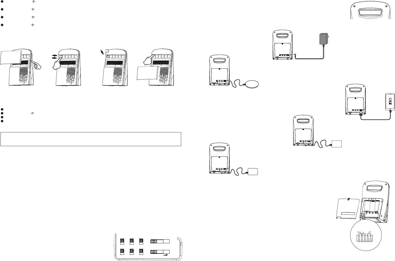
Replace the icon plate
After pairing the sensor/bell pusher, do not forget change the sensor indication icon come withe the sensor.
Please keep the original icon plate for unpair the zone.
Vib Out: Vibrator connect to this outlet. It provide 12V
output to drive the vibrator.
5V output: This is a standard USB socket. It provide DC5V / 1A to charge
the mobile device. The charge current depend on the max current of
power adaptor and the mobile device .(max. output current is 1A)
Alarm Out: This is a audio signal output. It
con connect to the external amplifier or other
alarm system.
Ext. Trigger: This is a external trigger input. you
can apply a 3-12V DC to trigger this input.
Open the display lens
by nails
Tack out the icon plate and
replace the correct one.
Press the top of the icon
plate to fix it. Cover back
the display lens
Press the bottom of the
icon plate. the top of the
icon plate will go out
NO NC +12V-
This receive provide some output terminal for special application.
Normal Open(NO) terminal:
This 2 terminal pin is open circuit normally, It will close circuit when
the receiver be triggered. The duration is depend on the timer switch
setting.
Normal Close (NC) terminal:
This 2 terminal pin is close circuit normally, It will open circuit when the
receiver be triggered. The duration is depend on the timer switch
setting.
Normally open and normally closed can only choose one connection.
(The rating do not exceed48V/500mA)
12V out terminal:
This 2 terminal pin can provide 12v output to drive some device when
the receiver be triggered. The duration is depend on the timer switch
setting. The device current do not exceed 200mA.
3 4

FCC Statement:
This equipment has been tested and found to comply with the limits for a Class B digital device, pursuant
to part 15 of the FCC Rules. These limits are designed to provide reasonable protection against harmful
interference in a residential installation. This equipment generates, uses and can radiate radio
frequency energy and, if not installed and used in accordance with the instructions, may cause harmful
interference to radio communications.
However, there is no guarantee that interference will not occur in a particular installation. If this
equipment does cause harmful interference to radio or television reception, which can be determined by
turning the equipment off and on, the user is encouraged to try to correct the interference by one or more
of the following measures:
* Reorient or relocate the receiving antenna.
* Increase the separation between the equipment and receiver.
* Connect the equipment to an outlet on a circuit different from that to which the receiver is connected.
This device complies with part 15 of the FCC rules. Operation is subject to the following two conditions:
(1) This device may not cause harmful interference, and (2) this device must accept any interference
received, including interference that may cause undesired operation.
Note: Modifications to this product will void the user's authority to operate this equipment.
RoHS
2002/95/EC