Verifone OMNI3600 Wireless Handheld Point of Sale Terminal User Manual mobitex
VeriFone Inc Wireless Handheld Point of Sale Terminal mobitex
Verifone >
Contents
- 1. ex9 manual part 1
- 2. ex9 manual part 2
- 3. ex9 manual part 3
- 4. ex9 manual last part
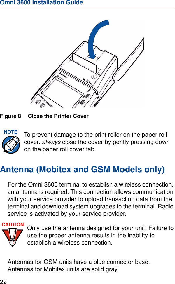
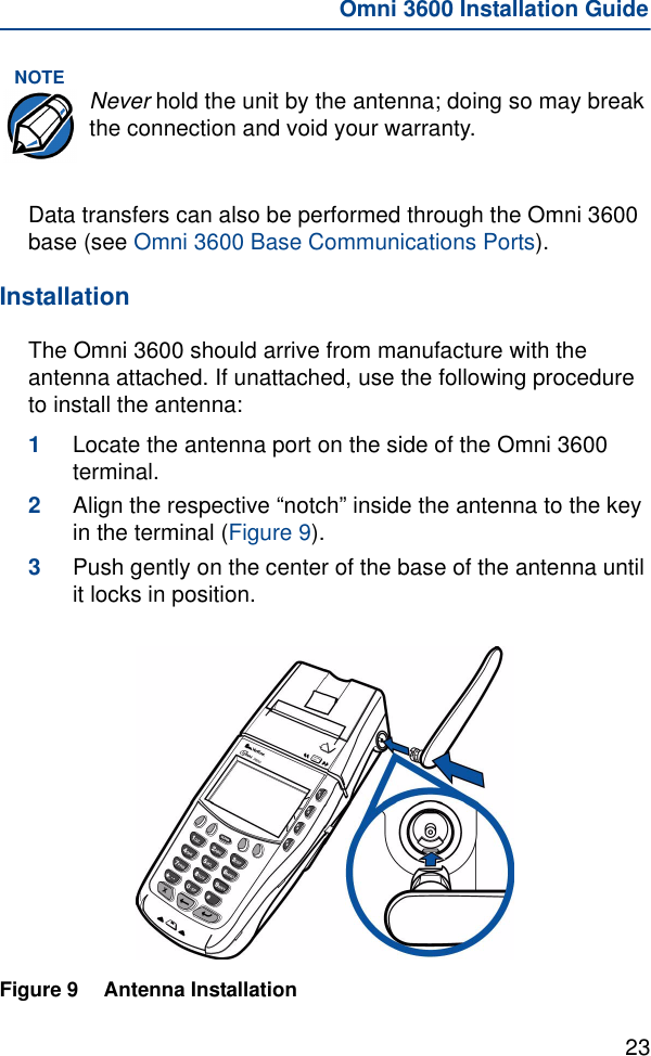
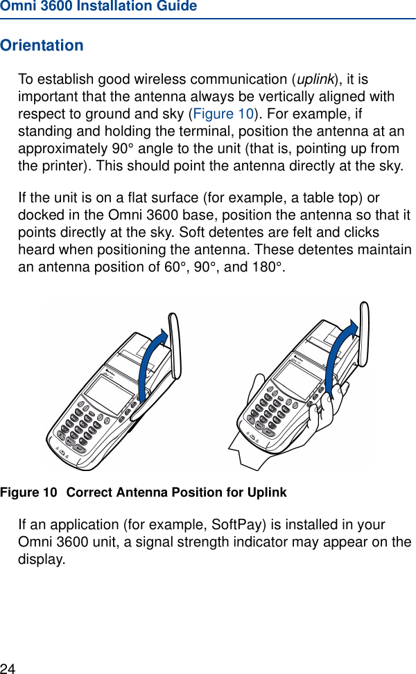
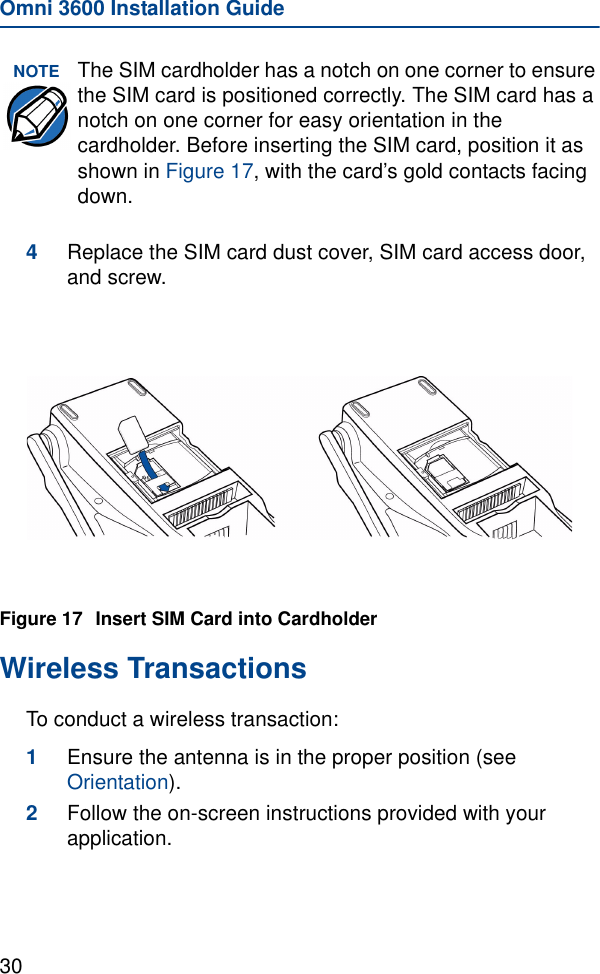
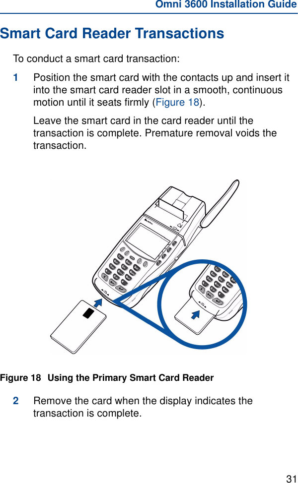
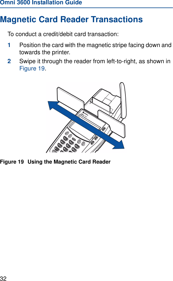
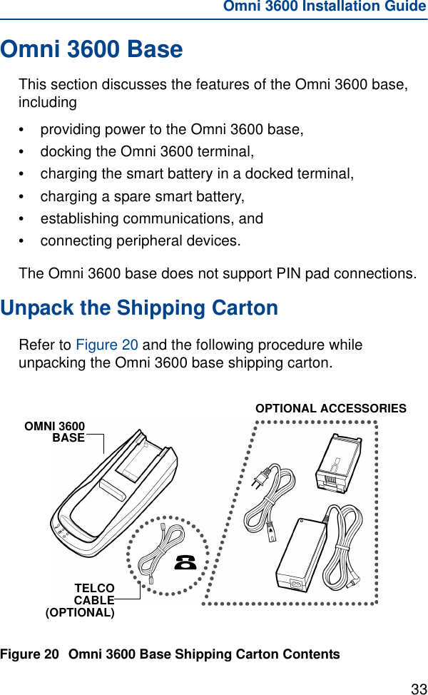
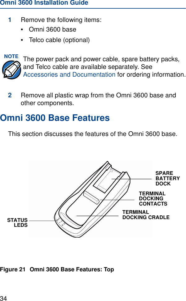
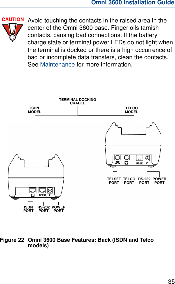
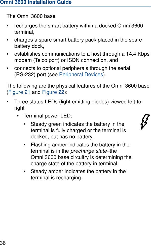
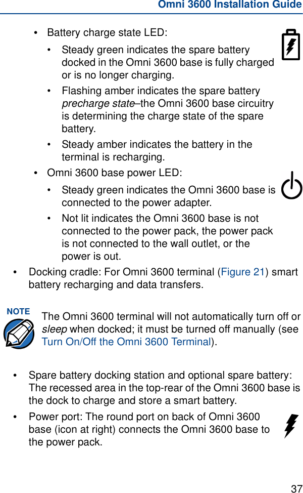
ex9 manual part 3