Verifone OMNI3600 Wireless Handheld Point of Sale Terminal User Manual mobitex
VeriFone Inc Wireless Handheld Point of Sale Terminal mobitex
Verifone >
Contents
- 1. ex9 manual part 1
- 2. ex9 manual part 2
- 3. ex9 manual part 3
- 4. ex9 manual last part
ex9 manual part 3
Omni 3600 Installation Guide
18
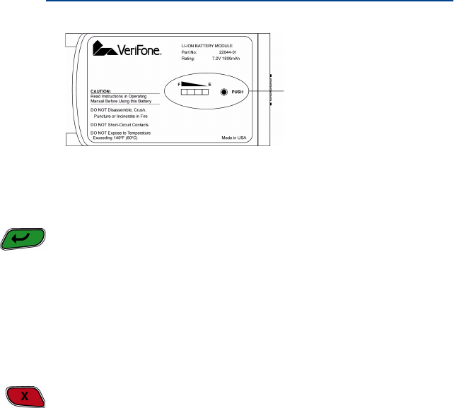
To determine the charge state of the battery, push the “target”
icon (shown in Figure 5) on the bottom of the battery. The bar
LED status indicators on the battery each indicate 25% of the
charge state. The E LED blinks at the 10% charge state. The
battery charge state displays at the bottom of the first
copyright screen when the terminal is turned on.
When the battery charge state reaches 10%, the E LED
(Figure 5) blinks, indicating the low charge state.
The smart battery has a safety circuit to protect the Li-ion cells
from overcharging and over-discharging. If the battery is over-
discharged, safety circuit shuts down the battery and none of
the indicator LEDs (see Figure 5) on the battery pack blink.
The battery must then be recharged to restore operation.
If the Omni 3600 terminal is already running an application (for
example, SoftPay), a battery status indicator appears on the
display.
NOTE Conserve battery power by turning the Omni 3600
terminal off when not in use. If the terminal is not to be
used for several days, remove the battery from the
terminal as it continues to discharge even when the
terminal is turned off.
NOTE The Omni 3600 terminal automatically shuts off when
the smart battery reaches the critically low charge state.
If this occurs, the smart battery must recharge a
minimum of 1/2 hour before it can power the terminal.
19
Omni 3600 Installation Guide
Figure 5 Smart Battery Charge Indicator LEDs and Test Button
Turn On/Off the Omni 3600 Terminal
When the smart battery completes its initial charge, turn on the
Omni 3600 terminal by pressing the green ENTER/ON key (icon
at left) for approximately 3 sec. The display screen lights and
displays the initial VeriFone copyright screen. If an application
is loaded in the terminal, it starts after the initial VeriFone
copyright screen and displays a unique copyright screen. If no
application is loaded in the terminal, DOWNLOAD NEEDED
appears on screen after the initial VeriFone copyright screen.
Turn off the Omni 3600 terminal by pressing the red CANCEL/
OFF key (icon at left) continuously until the cancel tone is heard
(approximately 4 sec.). First a series of beeps is heard, then
the cancel tone. The unit then shuts off.
Paper Installation
The internal thermal printer uses a roll of single-ply, thermal-
sensitive paper, approximately 57 millimeters (2.25 inches)
wide and 25–33 meters (82–108.26 feet) long. A pink out-of-
paper indicator line appears on the edge of the paper
approximately 18 inches before the end of the roll. After this
line appears, there is enough paper remaining on the roll to
conclude at least one transaction.
BATTERY CHARGE STATE
TEST BUTTON AND
STATUS INDICATOR LEDS
Omni 3600 Installation Guide
20
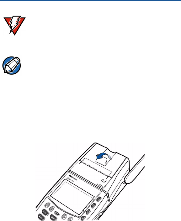
To install the paper roll in the internal thermal printer:
1Lift paper roll cover tab to unlock the printer door
(Figure 6).
2Rotate the printer door up and back. Note that the door is
hinged; it is not necessary to remove it from the unit.
Figure 6 Open the Printer Cover
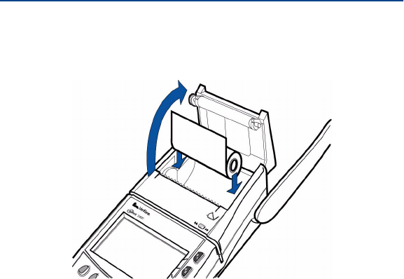
3Loosen the glued leading edge of the paper from the roll.
4Hold the paper roll so paper feeds from the bottom
(Figure 7) and pull approximately two inches of paper free
of the roll.
WARNING Poor-quality paper may jam the printer. Order high-
quality paper from VeriFone; refer to the ordering
process listed in Accessories and Documentation.
NOTE Store thermal paper in a dry, dark, cool place. Handle
thermal paper carefully; impact, friction, high
temperatures, humidity, light, and oils affect the color and
storage characteristics.
21
Omni 3600 Installation Guide
5Drop the paper roll into the printer tray, allowing the free
paper to extend outside the printer door (Figure 7).
Figure 7 Load Paper
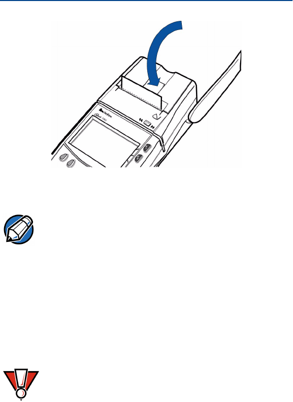
6Close the cover by gently pressing directly on the paper
roll cover tab until it clicks shut. Allow a small amount of
paper to extend outside the cover, as shown in Figure 8.
Omni 3600 Installation Guide
22
Figure 8 Close the Printer Cover
Antenna (Mobitex and GSM Models only)
For the Omni 3600 terminal to establish a wireless connection,
an antenna is required. This connection allows communication
with your service provider to upload transaction data from the
terminal and download system upgrades to the terminal. Radio
service is activated by your service provider.
Antennas for GSM units have a blue connector base.
Antennas for Mobitex units are solid gray.
NOTE To prevent damage to the print roller on the paper roll
cover, always close the cover by gently pressing down
on the paper roll cover tab.
CAUTION Only use the antenna designed for your unit. Failure to
use the proper antenna results in the inability to
establish a wireless connection.
23
Omni 3600 Installation Guide
Data transfers can also be performed through the Omni 3600
base (see Omni 3600 Base Communications Ports).
Installation
The Omni 3600 should arrive from manufacture with the
antenna attached. If unattached, use the following procedure
to install the antenna:
1Locate the antenna port on the side of the Omni 3600
terminal.
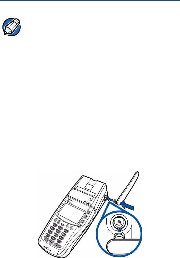
2Align the respective “notch” inside the antenna to the key
in the terminal (Figure 9).
3Push gently on the center of the base of the antenna until
it locks in position.
Figure 9 Antenna Installation
NOTE Never hold the unit by the antenna; doing so may break
the connection and void your warranty.

Omni 3600 Installation Guide
24
Orientation
To establish good wireless communication (uplink), it is
important that the antenna always be vertically aligned with
respect to ground and sky (Figure 10). For example, if
standing and holding the terminal, position the antenna at an
approximately 90° angle to the unit (that is, pointing up from
the printer). This should point the antenna directly at the sky.
If the unit is on a flat surface (for example, a table top) or
docked in the Omni 3600 base, position the antenna so that it
points directly at the sky. Soft detentes are felt and clicks
heard when positioning the antenna. These detentes maintain
an antenna position of 60°, 90°, and 180°.
Figure 10 Correct Antenna Position for Uplink
If an application (for example, SoftPay) is installed in your
Omni 3600 unit, a signal strength indicator may appear on the
display.

25
Omni 3600 Installation Guide
Replace the Antenna
If your Omni 3600 terminal has difficulties completing wireless
transactions, you may have to replace the antenna. Use the
following procedure to replace the antenna:
1Remove the existing antenna from the Omni 3600
terminal:
aRotate the antenna to align with the base of the unit,
pointing away from the back.
bGrasp the base of the antenna, close to the body of
the terminal.
cPull gently out until the antenna unsnaps from the
antenna port.
2Align the respective notch inside the new antenna to the
key in the antenna port on the terminal (Figure 9).
3Push gently on the center of the base of the newly
installed antenna until it locks in position.
Install/Replace MSAM Cards
When you first receive your Omni 3600 terminal, you may
need to install a merchant smart card or one or more
micromodule-sized security account manager (MSAM) cards,
or you may need to replace old cards. The following procedure
describes MSAM card installation.
CAUTION Observe standard precautions for handling
electrostatically sensitive devices. Electrostatic
discharges can damage this equipment. An anti-static
wrist strap grounded to a metal surface is
recommended.
Omni 3600 Installation Guide
26
1Remove the battery (see Smart Battery).
2Open the MSAM door located beneath the battery
(Figure 11):
aPush down and back on the raised arrow on the door.
bLift up on the raised arrow with the tip of your index
finger.
cOpen the door until it is in the upright position, resting
against the end of the terminal.
Figure 11 Open the MSAM Access Door
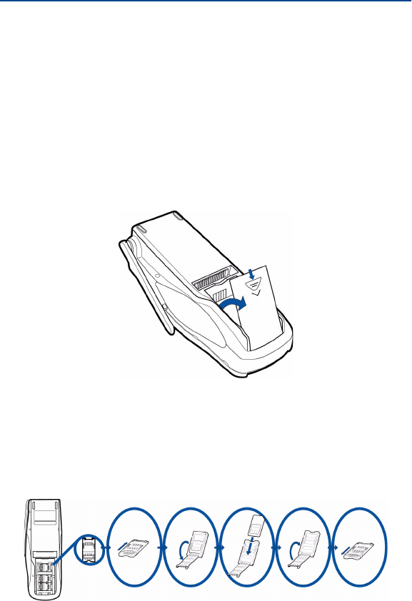
The three MSAM cardholders are now accessible. Each
cardholder consists of a hinged tilt-up cover attached to a
connector base (Figure 12).
Figure 12 MSAM Card Installation
27
Omni 3600 Installation Guide
3Access the MSAM cardholders (reference Figure 12):
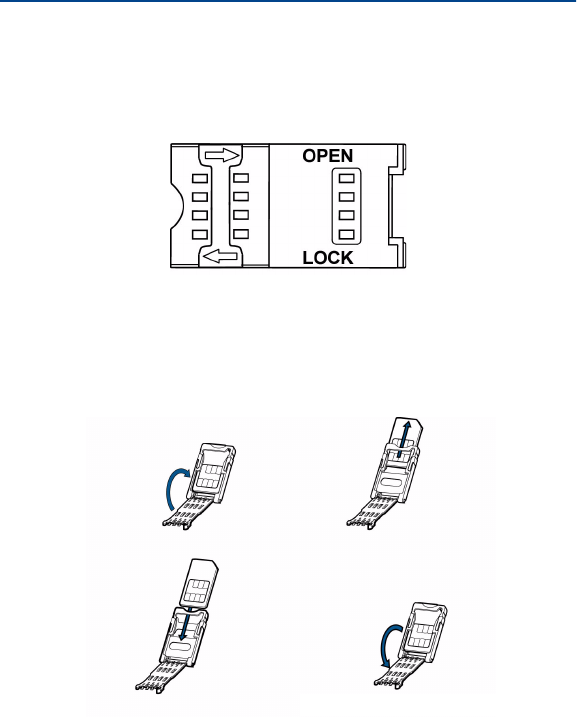
aUnlock the cardholder: Slide the lock plate to the
unlocked position, in the OPEN direction (Figure 13).
Figure 13 MSAM Cardholder Lock Plate Detail
bOpen the cardholder by pivoting the cover on its hinge
away from the connector base (Figure 14).
Figure 14 Insert MSAM Card into Cardholder
4Remove any previously installed MSAM card by sliding
the card from the cover.

Omni 3600 Installation Guide
28
5Install an MSAM card by aligning the card and carefully
sliding it within the guides on the cover until fully inserted.
6Close the cover (Figure 14).
7Lock each MSAM cardholder by sliding its locking plate
towards the LOCK arrow until the plate stops (Figure 13).
8Close the MSAM door.
9Replace the smart battery.
Install/Replace SIM Card (GSM models)
The SIM (Subscriber Identity Module) card is a smart card
inserted in the Omni 3600 GSM terminal that contains your
GSM radio account information. Use the following procedure
to replace or install a SIM card.
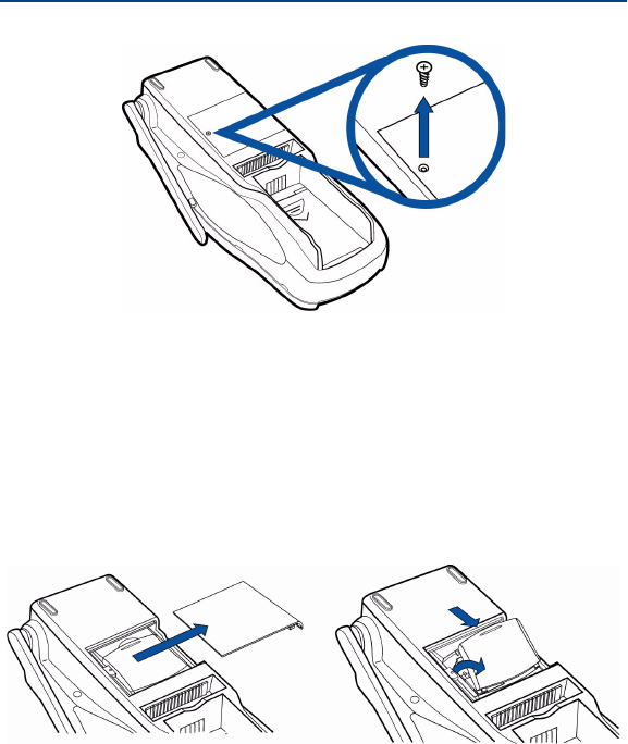
1Remove screw from SIM card access door on back of
Omni 3600 terminal (Figure 15).
NOTE The cardholder has a set of contacts and a notch on one
corner to ensure the MSAM card is positioned correctly
when the cover is closed. The MSAM card has a notch
on one corner to ensure it is correctly positioned in the
cardholder. Before inserting the MSAM card, position it
as shown in Figure 14.
CAUTION To avoid damage to the MSAM cardholders, ensure
each cardholder is locked before closing the MSAM
door.
29
Omni 3600 Installation Guide
Figure 15 Remove SIM Door Screw
2Open the SIM card dust cover (Figure 16):
aWedge your fingernail or a thin coin in the crescent
shaped recess above the dust cover.
bPush dust cover towards arrow shown in Figure 16 to
open and remove cover from unit.
Figure 16 Slide Off SIM Card Access Door and Remove Dust Cover
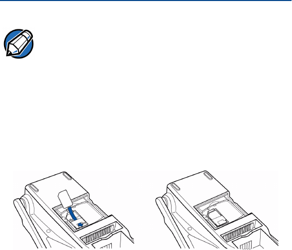
3Slide the SIM card supplied by your provider into the
cardholder (Figure 17).
Omni 3600 Installation Guide
30
4Replace the SIM card dust cover, SIM card access door,
and screw.
Figure 17 Insert SIM Card into Cardholder
Wireless Transactions
To conduct a wireless transaction:
1Ensure the antenna is in the proper position (see
Orientation).
2Follow the on-screen instructions provided with your
application.
NOTE The SIM cardholder has a notch on one corner to ensure
the SIM card is positioned correctly. The SIM card has a
notch on one corner for easy orientation in the
cardholder. Before inserting the SIM card, position it as
shown in Figure 17, with the card’s gold contacts facing
down.
31
Omni 3600 Installation Guide
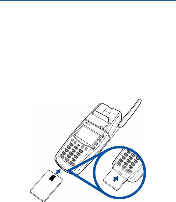
Smart Card Reader Transactions
To conduct a smart card transaction:
1Position the smart card with the contacts up and insert it
into the smart card reader slot in a smooth, continuous
motion until it seats firmly (Figure 18).
Leave the smart card in the card reader until the
transaction is complete. Premature removal voids the
transaction.
Figure 18 Using the Primary Smart Card Reader
2Remove the card when the display indicates the
transaction is complete.
Omni 3600 Installation Guide
32
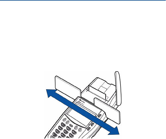
Magnetic Card Reader Transactions
To conduct a credit/debit card transaction:
1Position the card with the magnetic stripe facing down and
towards the printer.
2Swipe it through the reader from left-to-right, as shown in
Figure 19.
Figure 19 Using the Magnetic Card Reader
33
Omni 3600 Installation Guide
Omni 3600 Base
This section discusses the features of the Omni 3600 base,
including
•providing power to the Omni 3600 base,
•docking the Omni 3600 terminal,
•charging the smart battery in a docked terminal,
•charging a spare smart battery,
•establishing communications, and
•connecting peripheral devices.
The Omni 3600 base does not support PIN pad connections.
Unpack the Shipping Carton
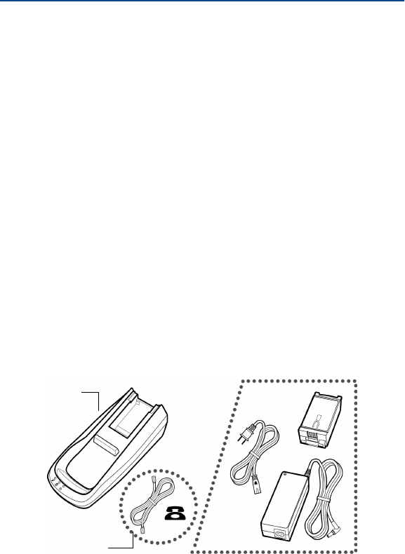
Refer to Figure 20 and the following procedure while
unpacking the Omni 3600 base shipping carton.
Figure 20 Omni 3600 Base Shipping Carton Contents
OMNI 3600
BASE
TELCO
CABLE
(OPTIONAL)
OPTIONAL ACCESSORIES
Omni 3600 Installation Guide
34
1Remove the following items:
•Omni 3600 base
•Telco cable (optional)
2Remove all plastic wrap from the Omni 3600 base and
other components.
Omni 3600 Base Features
This section discusses the features of the Omni 3600 base.
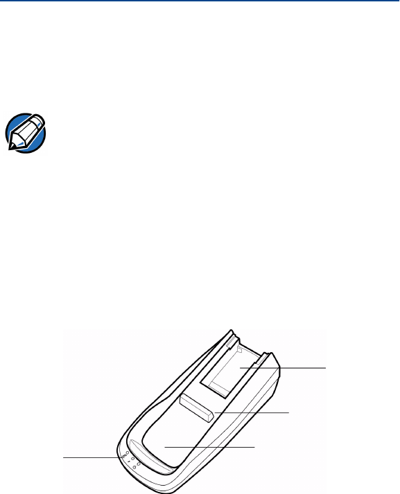
Figure 21 Omni 3600 Base Features: Top
NOTE The power pack and power cable, spare battery packs,
and Telco cable are available separately. See
Accessories and Documentation for ordering information.
STATUS
LEDS
SPARE
BATTERY
DOCK
TERMINAL
DOCKING
CONTACTS
TERMINAL
DOCKING CRADLE
35
Omni 3600 Installation Guide
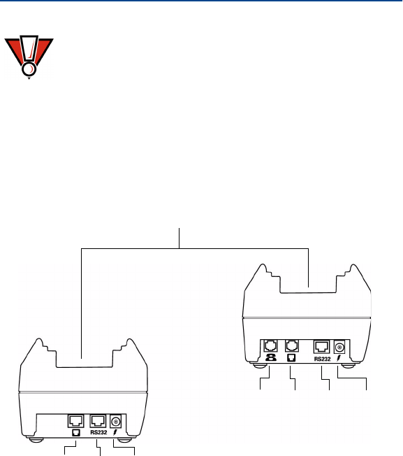
Figure 22 Omni 3600 Base Features: Back (ISDN and Telco
models)
CAUTION Avoid touching the contacts in the raised area in the
center of the Omni 3600 base. Finger oils tarnish
contacts, causing bad connections. If the battery
charge state or terminal power LEDs do not light when
the terminal is docked or there is a high occurrence of
bad or incomplete data transfers, clean the contacts.
See Maintenance for more information.
POWER
PORT
RS-232
PORT
TELCO
PORT
TELSET
PORT
TERMINAL DOCKING
CRADLE
POWER
PORT
RS-232
PORT
ISDN
PORT
ISDN
MODEL TELCO
MODEL

Omni 3600 Installation Guide
36
The Omni 3600 base
•recharges the smart battery within a docked Omni 3600
terminal,
•charges a spare smart battery pack placed in the spare
battery dock,
•establishes communications to a host through a 14.4 Kbps
modem (Telco port) or ISDN connection, and
•connects to optional peripherals through the serial
(RS-232) port (see Peripheral Devices).
The following are the physical features of the Omni 3600 base
(Figure 21 and Figure 22):
•Three status LEDs (light emitting diodes) viewed left-to-
right
•Terminal power LED:
•Steady green indicates the battery in the
terminal is fully charged or the terminal is
docked, but has no battery.
•Flashing amber indicates the battery in the
terminal is in the precharge state–the
Omni 3600 base circuitry is determining the
charge state of the battery in terminal.
•Steady amber indicates the battery in the
terminal is recharging.
37
Omni 3600 Installation Guide
•Battery charge state LED:
•Steady green indicates the spare battery
docked in the Omni 3600 base is fully charged
or is no longer charging.
•Flashing amber indicates the spare battery
precharge state–the Omni 3600 base circuitry
is determining the charge state of the spare
battery.
•Steady amber indicates the battery in the
terminal is recharging.
•Omni 3600 base power LED:
•Steady green indicates the Omni 3600 base is
connected to the power adapter.
•Not lit indicates the Omni 3600 base is not
connected to the power pack, the power pack
is not connected to the wall outlet, or the
power is out.
•Docking cradle: For Omni 3600 terminal (Figure 21) smart
battery recharging and data transfers.
•Spare battery docking station and optional spare battery:
The recessed area in the top-rear of the Omni 3600 base is
the dock to charge and store a smart battery.
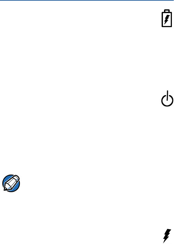
•Power port: The round port on back of Omni 3600
base (icon at right) connects the Omni 3600 base to
the power pack.
NOTE The Omni 3600 terminal will not automatically turn off or
sleep when docked; it must be turned off manually (see
Turn On/Off the Omni 3600 Terminal).
Omni 3600 Installation Guide
38
•Communications ports: The ports on the back of the
Omni 3600 base allow telephone, ISDN, or LAN line
connectivity and peripheral device support.
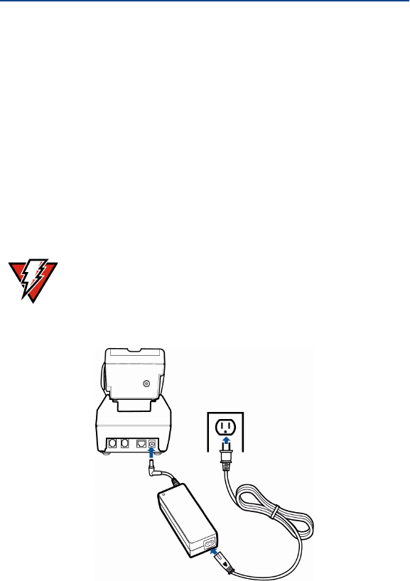
Power Connection
The Omni 3600 base must be plugged in to a power outlet to
•recharge a smart battery in a docked terminal,
•charge spare smart batteries,
•communicate with peripheral devices, and
•establish Telco or ISDN host connections.
Figure 23 Power Pack Connection (Docked Terminal)
WARNING
Do not plug the power pack into an outdoor outlet.