ViaSat AT2220 Fixed L-Band satellite modem with WLAN and Bluetooth User Manual II
ViaSat, Inc. Fixed L-Band satellite modem with WLAN and Bluetooth II
ViaSat >
Contents
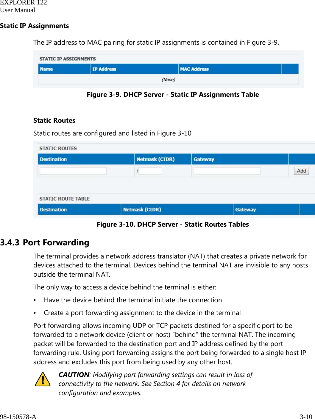
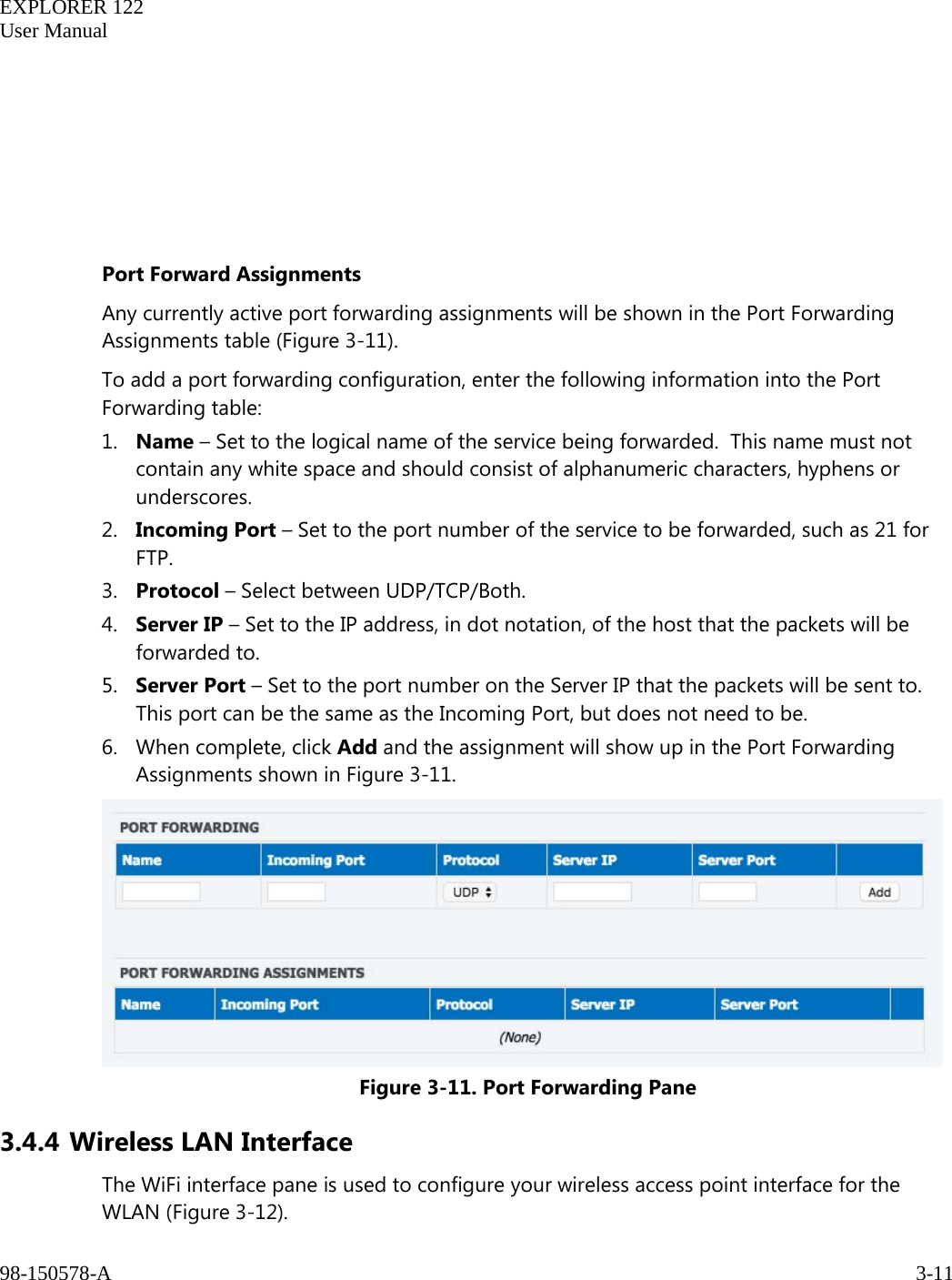
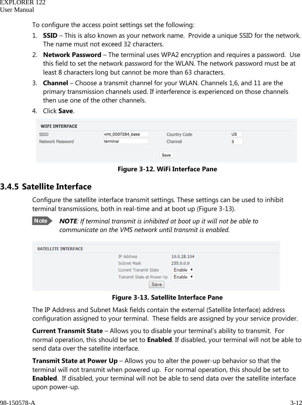
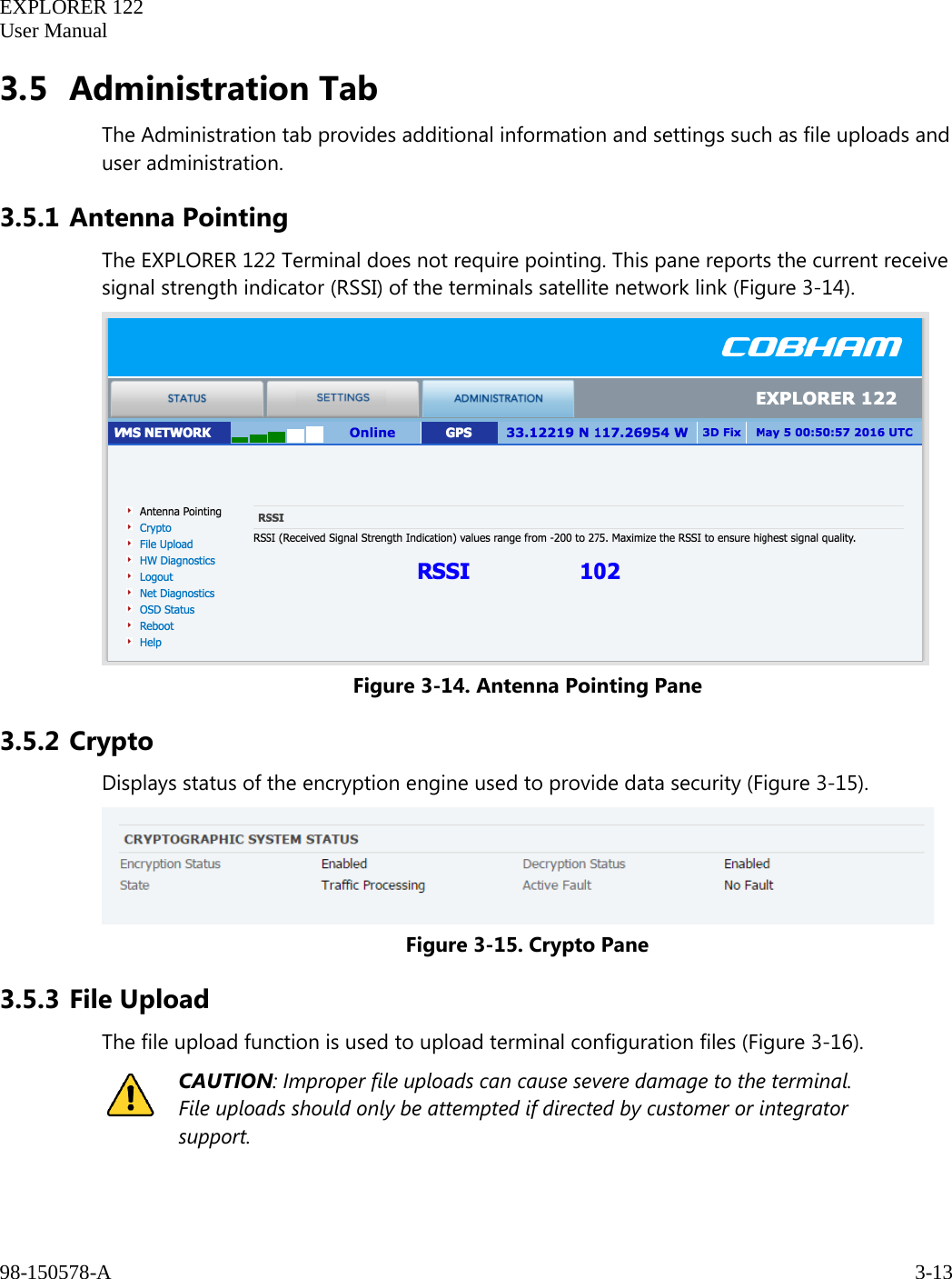
- 1. User Manual
- 2. User Manual I
- 3. User Manual II
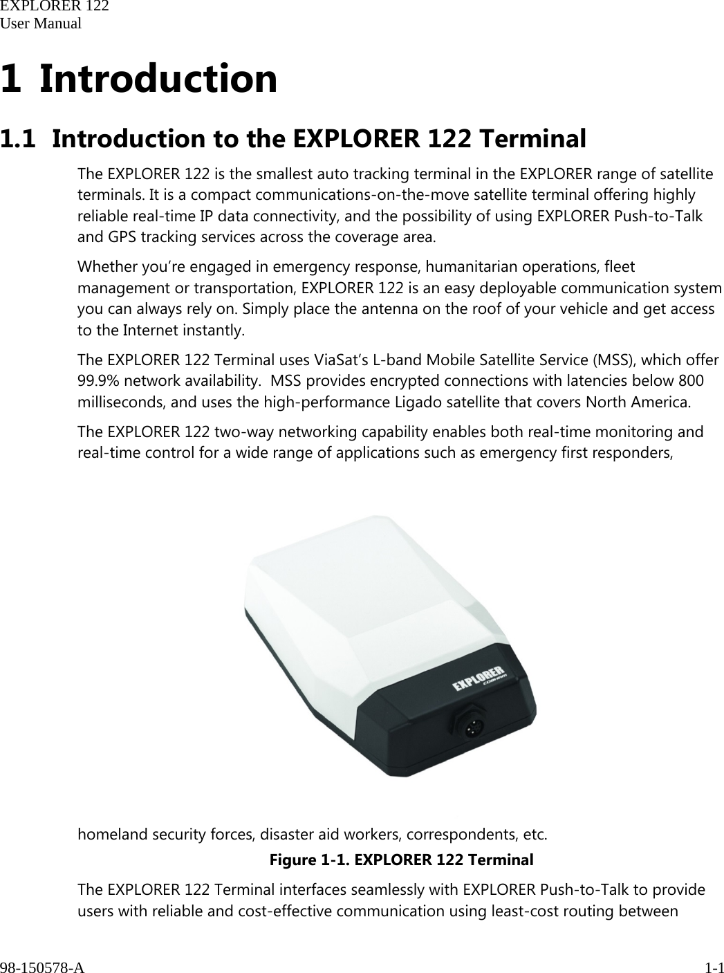
User Manual II