ViaSat AT2220 Fixed L-Band satellite modem with WLAN and Bluetooth User Manual II
ViaSat, Inc. Fixed L-Band satellite modem with WLAN and Bluetooth II
ViaSat >
Contents
- 1. User Manual
- 2. User Manual I
- 3. User Manual II
User Manual II

98-150578-A
Document Number: 98-150578-A
Release Date: May 11 2016
Disclaimer
Any responsibility or liability for loss or damage in connection with the use of this product
and the accompanying documentation is disclaimed by Thrane & Thrane A/S. The
information in this manual is provided for information purposes only, is subject to change
without notice and may contain errors or inaccuracies. Manuals issued by Thrane & Thrane
A/S are periodically revised and updated. Anyone relying on this information should acquire
the most current version e.g. from www.cobham.com/satcom, Service and support, or from
the distributor. Thrane & Thrane A/S is not responsible for the content or accuracy of any
translations or reproductions, in whole or in part, of this manual from any other source. In
the event of any discrepancies, the English version shall be the governing text.
Thrane & Thrane A/S is trading as Cobham SATCOM.
Copyright
© 2016 Thrane & Thrane A/S. All rights reserved.
Trademark Acknowledgements
• Google Chrome™ is a trademark or registered trademark of Google, Inc.
• Other product and company names mentioned in this manual may be trademarks or
trade names of their respective owners.
This technical data is subject to the United States (U.S.) Export Administration Regulations (EAR).
Diversion contrary to U.S. law is prohibited.

EXPLORER 122
User Manual
98-150578-A i
FCC Regulatory Information
Compliance Statement (Part 15.19)
The enclosed hardware device complies with Part 15 of the FCC Rules. Operation is subject
to the following two conditions:
(1) This device may not cause harmful interference, and
(2) This device must accept any interference received including interference that may cause
undesired operation of the device.
Warning (Part 15.21)
Changes or modifications not expressly approved by ViaSat could void the user’s authority
to operate the equipment. Manufacturer is not responsible for any radio or TV interference
caused by unauthorized modifications to this equipment.
Industry Canada (IC) Regulatory Information
This device complies with Industry Canada license-exempt RSS standard(s). Operation is
subject to the following two conditions:
(1) this device may not cause interference, and
(2) this device must accept any interference, including interference that may cause undesired
operation of the device.
Le présent appareil est conforme aux CNR d'Industrie
Canada applicables aux appareils radio exempts de licence. L'exploitation est autorisée aux
deux conditions suivantes:
(1) l'appareil ne doit pas produire de brouillage, et
(2) l'utilisateur de l'appareil doit accepter tout brouillage radioélectrique subi, même si le
brouillage est susceptible d'en compromettre le fonctionnement.
This Class B digital apparatus complies with Canadian ICES-003, RSS-Gen and RSS-210.
Cet appareil numérique de la classe B est conforme à la norme NMB-003, CNR-Gen et CNR-
210 du Canada.
Open Source License Notification
This product incorporates various open source software packages that are distributed under
license terms as described at: http://www.viasat.com/FOSS-Usage

EXPLORER 122
User Manual
98-150578-A ii
Warnings, Cautions, and Notes
Text marked with “Warning”, “Caution” or “Note” show the following type of data:
General Safety Precautions
General safety precautions are as follows:
WARNING: There are no user-serviceable parts inside the terminal. The
terminal should only be opened by a technician that is trained and certified
to service the EXPLORER 122 Terminal.
WARNING: This device emits radio frequency (RF) energy when in transmit
mode. In order to comply with FCC RF Exposure limits, the unit must be
installed in such a way as to ensure that a minimum separation distance of
44 cm (18 inches) is maintained between the antenna and any nearby
persons.
WARNING: A Warning is an operation or maintenance procedure that,
if not obeyed, can cause injury or death.
CAUTION: A Caution is an operation or maintenance procedure that, if
not obeyed, can cause damage to the equipment.
NOTE: A Note gives information to help the reader.

EXPLORER 122
User Manual
98-150578-A iii
About this Manual
This manual contains information about the EXPLORER 122 Mobile Terminal, including
installation procedures, webpage operations, and troubleshooting procedures.
Supporting Documentation
The following list provides documentation associated with this user manual.
Product number Title
98-150579-A EXPLORER 122 Terminal Quick Start Guide
1216662 ViaSat MSS Terminal AT Command Interface
Additional information may be found on the Cobham website, located
at: http://www.cobham.com/satcom, select Service and Support > Cobham SATCOM Service
and Support > 24-7 Self Service Center / Technical Downloads.
Acronyms
Acronyms and Definitions
- A -
ADC ............................ Analog-Digital Conversion
AES ............................. Advanced Encryption Standard
ANSI ........................... American National Standards Institute
- B - BIT ............................... Built-in Self Tests
- D - DHCP ......................... Dynamic Host Configuration Protocol
- H - EIA .............................. Electronic Industries Alliance
EIRP ............................ Effective Isotropic Radiated Power
- E - Es/No ......................... Energy Symbol/Noise
- F -
FDD ............................ Full Duplex Mode
FIPS ............................ Federal Information Processing Standard
FL................................. Forward Link
FPGA .......................... Field Programmable Gate Array
FTP .............................. File Transfer Protocol
- G -
GB ............................... Gigabyte
GLONASS ................. GLObal NAvigational Satellite System
GNSS ......................... Global Navigational Satellite System
GPS ............................. Global Positioning System
- H - HTTP .......................... Hypertext Transfer Protocol
HW ............................. Hardware

EXPLORER 122
User Manual
98-150578-A iv
Acronyms and Definitions
- I -
IE ................................. Internet Explorer
IEEE ............................. Institute of Electrical and Electronics Engineers
IF ................................. Intermediate Frequency
IP ................................. Internet Protocol
IP66 ............................ Ingress Protection
- L -
LAN ............................ Local Area Network (Ethernet)
LHCP .......................... Left-Hand Circular Polarization
LOS ............................. Line of Sight
- M -
M2M .......................... Machine-to-Machine
MAC ........................... Media Access Control
Mbps ......................... Megabits per second
MMI ........................... Multi-Media Interface
MSS ............................ Mobile Satellite Services
- N - NAT ............................ Network Address Translator
- O - OSD ............................ Over-The-Air Software Download
OTA ............................ Over-The-Air
- P -
PC................................ Personal Computer
PLL .............................. Phase Locked Loop
POST .......................... Power On Self-Tests
- R -
RF ................................ Radio Frequency
RHCP.......................... Right-Hand Circular Polarization
RX ............................... Receive
- S - SCADA....................... Supervisory Control and Data acquisition
SSID ............................ Service Set Identifier
- T -
TCP ............................. Transmission Control Protocol
TIA .............................. Transmission Industry Association
TX ................................ Transmit
- U -
UDP ............................ User Datagram Protocol
URL ............................. Uniform Resource Identifier
UV ............................... Ultra Violet
- V - VDC ............................ Voltage Direct Current
- W - WLAN ........................ Wireless Local Area Network
EXPLORER 122
User Manual
98-150578-A v
Table of Contents
1 Introduction .................................................................................................. 1-1
1.1 Introduction to the EXPLORER 122 Terminal ........................................................................... 1-1
1.2 Features of the EXPLORER 122 Terminal .................................................................................. 1-2
1.3 EXPLORER 122 Standard Equipment and Optional Accessories ............................................. 1-2
1.3.1 Standard Equipment ....................................................................................................................................................................................... 1-2
1.3.2 Optional Accessories ....................................................................................................................................................................................... 1-2
1.4 Key Specifications ....................................................................................................................... 1-4
2 Getting Started ............................................................................................. 2-1
2.1 Unpacking .................................................................................................................................... 2-1
2.2 Selecting Mounting Location ..................................................................................................... 2-1
2.3 Installation ................................................................................................................................... 2-3
2.4 Powering Up ................................................................................................................................ 2-4
2.5 Obtaining a GNSS Fix .................................................................................................................. 2-4
2.6 Antenna Pointing ........................................................................................................................ 2-5
2.7 Connecting the EXPLORER 122 Terminal to Other Equipment .............................................. 2-5
2.7.1 Interfaces .............................................................................................................................................................................................................. 2-5
2.7.2 Wired Interface .................................................................................................................................................................................................. 2-5
2.7.3 Wireless Interface ............................................................................................................................................................................................. 2-8
3 Connecting To The Explorer 122 Terminal................................................. 3-1
3.1 Web Server Connection .............................................................................................................. 3-1
3.1.1 Address/Port Number .................................................................................................................................................................................... 3-1
3.1.2 Protocol ................................................................................................................................................................................................................ 3-1
3.1.3 Web Browsers Supported ............................................................................................................................................................................. 3-2
3.2 Login ............................................................................................................................................. 3-3
3.3 Status Tab .................................................................................................................................... 3-4
3.3.1 Network ................................................................................................................................................................................................................ 3-4
3.3.2 GNSS ...................................................................................................................................................................................................................... 3-5
3.3.3 System Status ..................................................................................................................................................................................................... 3-5
3.3.4 Logs ........................................................................................................................................................................................................................ 3-6
3.3.5 Versions ................................................................................................................................................................................................................ 3-7
3.4 Settings Tab ................................................................................................................................. 3-7
3.4.1 Network Interface ............................................................................................................................................................................................. 3-8
3.4.2 DHCP Server ....................................................................................................................................................................................................... 3-8
3.4.3 Port Forwarding.............................................................................................................................................................................................. 3-10
3.4.4 Wireless LAN Interface ................................................................................................................................................................................ 3-11
3.4.5 Satellite Interface ........................................................................................................................................................................................... 3-12
3.5 Administration Tab ................................................................................................................... 3-13
3.5.1 Antenna Pointing ........................................................................................................................................................................................... 3-13
3.5.2 Crypto ................................................................................................................................................................................................................. 3-13
EXPLORER 122
User Manual
98-150578-A vi
3.5.3 File Upload ....................................................................................................................................................................................................... 3-13
3.5.4 HW Diagnostics .............................................................................................................................................................................................. 3-14
3.5.5 Logout ................................................................................................................................................................................................................ 3-14
3.5.6 Net Diagnostics .............................................................................................................................................................................................. 3-14
3.5.7 OSD Status ....................................................................................................................................................................................................... 3-16
3.5.8 Reboot ................................................................................................................................................................................................................ 3-16
4 Troubleshooting, Maintenance, And Technical Support .......................... 4-1
4.1 Self-Tests ...................................................................................................................................... 4-1
4.2 Troubleshooting Guide ............................................................................................................... 4-2
4.3 Preventative Maintenance ......................................................................................................... 4-4
4.4 Warranty ...................................................................................................................................... 4-4
4.5 Serviceable Parts ......................................................................................................................... 4-4
4.6 Customer Support ....................................................................................................................... 4-5
List of Figures
Figure 1-1. EXPLORER 122 Terminal ......................................................................................................................................................... 1-1
Figure 2-1. Terminal Location – Line of Sight ........................................................................................................................................ 2-1
Figure 2-2. Terminal Mounting Hole Locations .................................................................................................................................... 2-3
Figure 2-3. Terminal Mounting Example ................................................................................................................................................. 2-4
Figure 2-4 EXPLORER 122 Terminal Connector Pinout Drawing ................................................................................................... 2-5
Figure 2-5 Power Harness Wiring .............................................................................................................................................................. 2-7
Figure 3-1. Login Screen ................................................................................................................................................................................ 3-3
Figure 3-2. Failed Login .................................................................................................................................................................................. 3-3
Figure 3-3. Status Tab ..................................................................................................................................................................................... 3-4
Figure 3-4. Logs Pane...................................................................................................................................................................................... 3-6
Figure 3-5. Network Interface Pane ........................................................................................................................................................... 3-8
Figure 3-6. DHCP Server - Active Leases ................................................................................................................................................. 3-9
Figure 3-7. DHCP Server - Wired Ethernet DHCP Dynamic Address Pool ................................................................................. 3-9
Figure 3-8. DHCP Server - WLAN DHCP Dynamic Address Pool ................................................................................................... 3-9
Figure 3-9. DHCP Server - Static IP Assignments Table ................................................................................................................. 3-10
Figure 3-10. DHCP Server - Static Routes Tables .............................................................................................................................. 3-10
Figure 3-11. Port Forwarding Pane ......................................................................................................................................................... 3-11
Figure 3-12. WiFi Interface Pane .............................................................................................................................................................. 3-12
Figure 3-13. Satellite Interface Pane ...................................................................................................................................................... 3-12
Figure 3-14. Antenna Pointing Pane ...................................................................................................................................................... 3-13
Figure 3-15. Crypto Pane ............................................................................................................................................................................ 3-13
Figure 3-16. File Upload Pane ................................................................................................................................................................... 3-14
Figure 3-17. HW Diagnostics Pane ......................................................................................................................................................... 3-14
Figure 3-18. Logout Pane ........................................................................................................................................................................... 3-14
Figure 3-19. Net Diagnostics Pane ......................................................................................................................................................... 3-15
Figure 3-20. OSD Status Pane ................................................................................................................................................................... 3-16
Figure 3-21. Reboot Pane ........................................................................................................................................................................... 3-16
Figure A-1. Cable Assembly Preparation .............................................................................................................................................. A-5
EXPLORER 122
User Manual
98-150578-A vii
Figure A-2. Connector Part Description ................................................................................................................................................ A-6
Figure A-3. Cable Assembly - Step 1 ...................................................................................................................................................... A-6
Figure A-4. Cable Assembly - Step 2 ...................................................................................................................................................... A-6
Figure A-5. Cable Assembly - Step 3 ...................................................................................................................................................... A-6
Figure A-6. Cable Assembly - Step 4 ...................................................................................................................................................... A-7
Figure A-7. Cable Assembly - Step 5 ...................................................................................................................................................... A-7
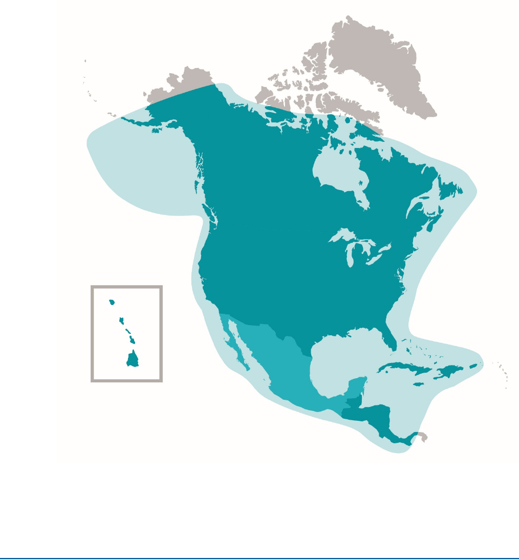
Figure B-1. Ligado’s SkyTerra-1 Satellite Coverage Map................................................................................................................. B-8
List of Tables
Table 1-1. EXPLORER 122 Terminal Key Specifications .................................................................................................................... 1-5
Table 2-1. EXPLORER 122 Terminal Connector Pinout Table......................................................................................................... 2-6
Table 3-1. Network Status ............................................................................................................................................................................ 3-5
Table 3-2. System Status Fault Codes ..................................................................................................................................................... 3-5
Table 4-1. Self-Tests ....................................................................................................................................................................................... 4-1
Table 4-2. Troubleshooting Guide ............................................................................................................................................................ 4-2
Table 4-3. Web MMI Status ......................................................................................................................................................................... 4-4
EXPLORER 122
User Manual
98-150578-A 1-1
1 Introduction
1.1 Introduction to the EXPLORER 122 Terminal
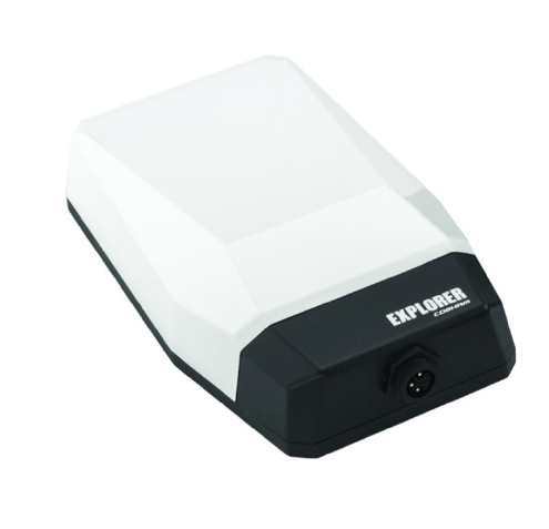
The EXPLORER 122 is the smallest auto tracking terminal in the EXPLORER range of satellite
terminals. It is a compact communications-on-the-move satellite terminal offering highly
reliable real-time IP data connectivity, and the possibility of using EXPLORER Push-to-Talk
and GPS tracking services across the coverage area.
Whether you’re engaged in emergency response, humanitarian operations, fleet
management or transportation, EXPLORER 122 is an easy deployable communication system
you can always rely on. Simply place the antenna on the roof of your vehicle and get access
to the Internet instantly.
The EXPLORER 122 Terminal uses ViaSat’s L-band Mobile Satellite Service (MSS), which offer
99.9% network availability. MSS provides encrypted connections with latencies below 800
milliseconds, and uses the high-performance Ligado satellite that covers North America.
The EXPLORER 122 two-way networking capability enables both real-time monitoring and
real-time control for a wide range of applications such as emergency first responders,
homeland security forces, disaster aid workers, correspondents, etc.
Figure 1-1. EXPLORER 122 Terminal
The EXPLORER 122 Terminal interfaces seamlessly with EXPLORER Push-to-Talk to provide
users with reliable and cost-effective communication using least-cost routing between
EXPLORER 122
User Manual
98-150578-A 1-2
terrestrial networks and satellites. AES-256 data link layer encryption is employed to ensure
the integrity of your data is not compromised.
Rugged IP66 dust and powerful water jet-resistant enclosure ensures reliable
communications in the toughest environments.
The guidelines below provide an overview of the terminal’s capabilities and basic operation.
For detailed configurations, please contact your EXPLORER 122 retailer, or the Cobham
customer support listed at the back of this manual.
1.2 Features of the EXPLORER 122 Terminal
Key Features of the EXPLORER 122 l.include:
• IP-based networking
• Wired Ethernet and wireless LAN Interfaces
• Built-in DHCP/NAT router
• Full-duplex connectivity
• Low-latency for instant text message transfer and real-time monitoring with no delays
• Embedded commercial GPS
• IP66
• 10-30 VDC Input
• Built-in Web MMI
• AES-256 Encryption
1.3 EXPLORER 122 Standard Equipment and Optional
Accessories
1.3.1 Standard Equipment
The EXPLORER 122 features the following standard accessories:
• EXPLORER 122 Terminal
• Connector Mating Kit
1.3.2 Optional Accessories
The EXPLORER 122 offers the following optional accessories:
• Magnetic Mounting Kit
• EXPLORER Push-to-Talk Connection Box
• Pre-Fabricated Over-molded cable
EXPLORER 122
User Manual
98-150578-A 1-3

EXPLORER 122
User Manual
98-150578-A 1-4
1.4 Key Specifications
The key specifications for the EXPLORER 122 Terminal are summarized in
Table 1-1 below.
Category Specification
Size: 250 x 146 x 62 (LxWxH mm.)
Weight < 2 Kg
Power Consumption 48 W max
Antenna Receive G/T -21.0 dB/K at Zenith
Antenna Transmit EIRP Up to +8 dBW at Zenith,
configurable in 0.1 dB steps
Frequency Range L-band
RX: 1525.0-1559.0 MHz
TX: 1626.5-1660.5 MHz
Modulation RX: BPSK, QPSK, 8-PSK and
16-APSK
TX: CRMA
Waterproof/Dustproof IP 66
Humidity up to 95% condensing at
45°C, per IEC 60068-2-30
Temperature - Operating -20°C to +55°C
Temperature - Storage -40°C to + 85°C
Solar Radiation 1120 W/m2; per IEC-60068-2-
5
Vibration (Operational) Random vibration of 1.05g
rms at vibration spectrum:
5 to 20 Hz: 0.02g2/Hz
20 to 150 Hz: -3dB/octave
Vibration (Survival) Transportation vibe per IEC
60068-2-64, Freq: 5-200Hz,
ASD: 1.0m2/s3
Shock (Operational) IEC 60068-2-64, 50m/s2, 11
ms

EXPLORER 122
User Manual
98-150578-A 1-5
Category Specification
Shock (Survival) Transportation shock per IEC
60068-2-29, A = 180m/s2, t =
6mS
Approval FCC, IC
Table 1-1. EXPLORER 122 Terminal Key Specifications
EXPLORER 122
User Manual
98-150578-A 2-1
2 Getting Started
2.1 Unpacking
The EXPLORER 122 Terminal is shipped in packaging materials that are uniquely designed
for the product. The following packing list describes the contents of a typical EXPLORER 122
shipment:
1. EXPLORER 122 Terminal
2. Mating Connector (assembly required)
Upon unpacking of the box, inventory the contents and inspect for sign of damages
during shipping. Contact your retailer in case of missing contents or noticeable defects.
To get started, the additional following items may be required:
3. Magnetic Mount (Platform Dependent)
NOTE: Contact your terminal integration partner for specific mounting
equipment.
2.2 Selecting Mounting Location
The EXPLORER 122 Terminal is designed for mobile vehicle installation. The terminal can be
permanently mounted with mounting screws or temporarily mounted with magnetic mounts
using the Installation kit (optional accessories).
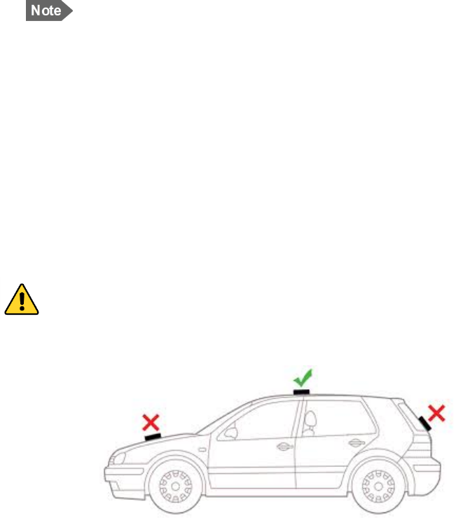
Mounting location should be selected to provide the terminal with a clear line-of-sight to
the operational satellite without any obstructions from the vehicle. Figure 2-1 illustrates
improper vs proper placement of the terminal.
Terminal should be placed as far away from other transmit antennas as possible.
WARNING: Terminal antenna should be kept at least 44 cm from direct
exposure to humans.
Figure 2-1. Terminal Location – Line of Sight
EXPLORER 122
User Manual
98-150578-A 2-2
EXPLORER 122
User Manual
98-150578-A 2-3
2.3 Installation
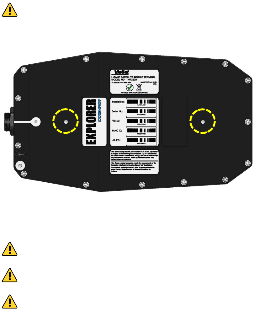
The EXPLORER 122 Terminal is 250 mm long by 146 mm wide (excluding connector) and 62
mm high. The terminal is designed to be magnetically-mounted to a vehicular platform. Two
size M5 mounting holes for magnetic mounts are located on the underside of the terminal
as shown in Figure 2-2.
CAUTION: The “Caution” icon identifies procedures or factors that can
affect the installation and configuration of the system (may damage or
render equipment inoperable).
Figure 2-2. Terminal Mounting Hole Locations
The terminal should be installed with the connector facing the rear of the vehicle. An
example of installation with a rear facing connector is shown in Figure 2-3.
CAUTION: Do not over tighten.
CAUTION: Do not apply pressure to the cable/connector during the
installation.
CAUTION: Do not force the connector pins to mate since this may damage
the pins.

EXPLORER 122
User Manual
98-150578-A 2-4
Figure 2-3. Terminal Mounting Example
2.4 Powering Up
The EXPLORER 122 Terminal is designed to automatically start up when DC power is applied
via an ignition sensor line. An ON/OFF power switch does not exist on the terminal.
At the completion of its power-up sequence, the terminal will automatically search for GNSS
and MSS satellite signals.
CAUTION: Do not stand in front of the unit once power is applied.
2.5 Obtaining a GNSS Fix
The MSS network does not require the terminal location to access the network. However,
terminal location enables optimal customer service.
At the completion of its power-up sequence, the terminal will automatically search for GNSS
and satellite signals. The default position reporting uses GPS satellites and the terminal will
EXPLORER 122
User Manual
98-150578-A 2-5
automatically attempt to get a new GPS lock every time it is powered on. Obtaining a lock
may take up to 5 minutes upon power-up.
2.6 Antenna Pointing
The EXPLORER 122 Terminal contains an electronically steerable antenna and does not require any
pointing by the user.
2.7 Connecting the EXPLORER 122 Terminal to Other
Equipment
2.7.1 Interfaces
The EXPLORER 122 Terminal offers the following wired interfaces via a multi-pin circular connector as
shown in Figure 2-4 and Table 2-1.
• DC Power
• LAN (Ethernet)
The EXPLORER 122 Terminal offers the following wireless interface:
• WLAN
2.7.2 Wired Interface
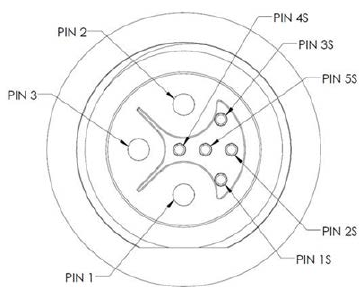
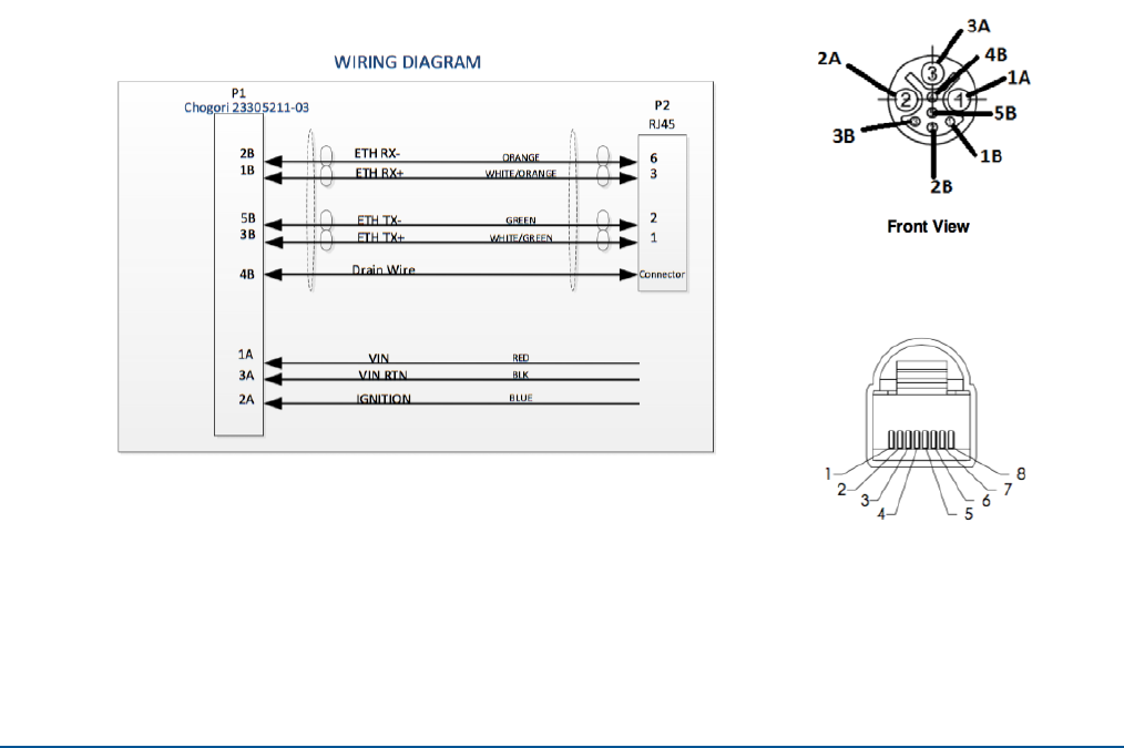
The pinout for the EXPLORER 122 Terminal connector is shown in Figure 2-4 and Table 2-1. For more
detailed cable instructions, refer to Appendix A.
Figure 2-4 EXPLORER 122 Terminal Connector Pinout Drawing

EXPLORER 122
User Manual
98-150578-A 2-6
Table 2-1. EXPLORER 122 Terminal Connector Pinout Table
Manufacturer
Terminal
Connector
Part Number
Cable
Connector
Part Number
Chogori
23305515-02
23305211-03
Pin
Number
Signal
Name
Description
1
VIN
+10 to +30 VDC Power
2 IGNITION Ignition Sense Line
3
VIN RTN
Power Return
1S
ETH RX+
Ethernet RX (+)
2S
ETH RX-
Ethernet RX (-)
3S
ETH TX+
Ethernet TX (+)
4S Drain Wire Ethernet Shield
5S
ETH TX-
Ethernet TX (-)
2.7.2.1 DC Power/Ignition Sense Interface
The terminal is designed to use +10 to +30 Volt Direct Current (VDC) negative ground
vehicle power systems. For safety, the EXPLORER 122 Terminal should be installed in a
circuit with an inline 7.5 A fuse that will trip during extended overcurrent events.
The nominal power consumption when receiving is approximately 9 Watts (W). During
transmission bursts or terminal boot up, the power draw can be up to 48 W.
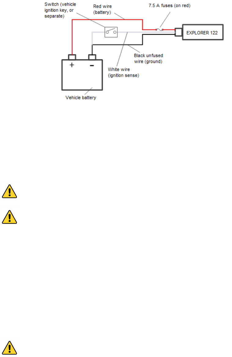
The EXPLORER 122 Terminal power on/off is controlled by the ignition sense line using
internal software, rather than a hard on/off switch on the red power line. Connect wires to
the battery and ignition switch as shown in the power harness wiring diagram.
EXPLORER 122
User Manual
98-150578-A 2-7
Figure 2-5 Power Harness Wiring
• When the ignition sense line is pulled low (less than 2 V), the EXPLORER 122 Terminal
performs a controlled shutdown sequence (under software control), de-registering and
saving any relevant operational data before powering off.
• When the ignition sense line is pulled high (5 to 30 V) or left unconnected, the EXPLORER
122 Terminal powers on.
CAUTION: Do not apply an input voltage to the terminal outside of the
specified range. This will permanently damage your terminal.
CAUTION: Observe proper Electro-static Discharge (ESD) practices during
installation.
The terminal protects against continuous inputs of -32 VDC to +32 VDC. Applying an input
voltage outside this range may permanently damage the terminal and cause it to become
non-operational.
2.7.2.2 Ethernet Interface
The Ethernet interface is defined by IEEE 802.3 for operation in 10Base-T and 100Base-TX
modes with the exception of the connector type. Cabling for Ethernet connectivity must
meet ANSI/TIA/EIA-568-A specifications for Category 5 or Category 5e cables. It is
recommended that the wired Ethernet interface be used for permanent installation. Contact
your terminal retailer for power/Ethernet cable or build your own cable assembly as shown
in section 6.
CAUTION: Use an Ethernet cable length no greater than 100m (328 ft.) to
ensure proper terminal operation.

EXPLORER 122
User Manual
98-150578-A 2-8
2.7.3 Wireless Interface
2.7.3.1 WLAN Interface
To connect your WLAN-enabled device to the EXPLORER 122, perform the following:
1. Make sure that WLAN feature on your device is turned on.
2. Place the device near the terminal.
3. Search for available WLAN networks on your device.
4. The default SSID will be vmt_<FTI>_base where <FTI> should be replaced with the fixed
terminal identifier unique to your terminal. Check the label on the terminal enclosure to
obtain the FTI.
5. Select the SSID of your terminal network when it appears on the list.
NOTE: Default password of your EXPLORER 122 WLAN is terminal
Encryption type is WPA2
6. It may take up to 2 minutes before a wireless connection is made and the configuration
webpage is available.

EXPLORER 122
User Manual
98-150578-A 3-1
3 Connecting to the EXPLORER 122
Terminal
The terminal will attempt to log in automatically to an available satellite network as soon as
it is powered on. The user interface is presented as a web page that is accessible from the
terminal. Features of the terminal can be controlled using the web interface. This interface is
used for determining terminal operational status, satellite link status and other terminal
information. This interface allows the user to perform control actions on the terminal for
certain activities such as reboot, managing IP addresses/ports, and controlling default
transmit power-up states.
NOTE: The webpage is only available through a local wired Ethernet or
WLAN connection to the terminal. This interface is not accessible through
the satellite network and will not transmit data over the satellite network.
3.1 Web Server Connection
3.1.1 Address/Port Number
The web server address will be the same as the terminal IP Address. By default, the terminal
IP addresses are:
• Wired Ethernet interface: 192.168.100.1
• WLAN interface: 192.168.200.1
The terminal IP Addresses are defined as the Destination IP address for incoming datagrams
to the terminal. These addresses are configurable through the configuration web page. The
web server port number is set to the standard port 80.
To connect to the terminal, enable DHCP settings on your PC or mobile device, and enter the
terminal IP address in your web browser.
If you do not wish to use the default DHCP server configuration, you will need to ensure that
your PC’s static IP address is on the same network as the terminal.
NOTE: The terminal will come from the factory with default DHCP server
settings to allow easy connection.
3.1.2 Protocol
The web server will use the HTTP protocol for connection with the platform interface devices.
EXPLORER 122
User Manual
98-150578-A 3-2
3.1.3 Web Browsers Supported
The EXPLORER 122 Terminal may be accessed by using the latest released version of Google
Chrome™.
EXPLORER 122
User Manual
98-150578-A 3-3
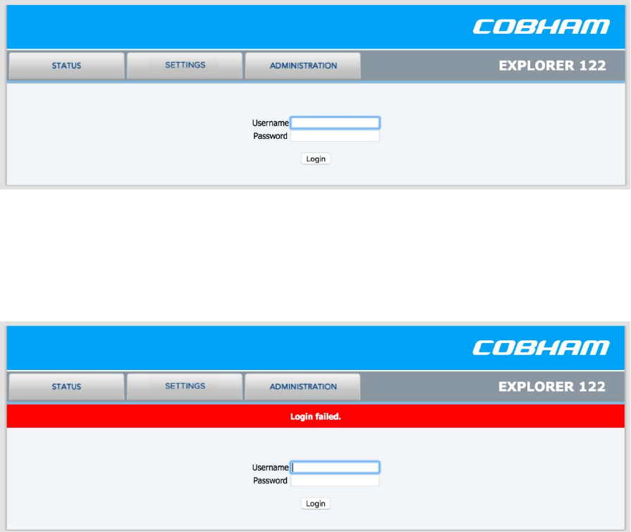
3.2 Login
The web server will present a login screen for the user to access all activities shown below.
Without the proper user login, no terminal functionality or status is available from the web
page. The terminal will be responsive to all login requests during all modes of operation.
Contact your terminal retailer or integrator for login credentials for your terminal.
Figure 3-1. Login Screen
The default Username/Password is admin/admin. After a successful login, the user will be
directed to the System Status page in Section 3.
After an unsuccessful login, the following web page with error banner is presented.
Figure 3-2. Failed Login
EXPLORER 122
User Manual
98-150578-A 3-4
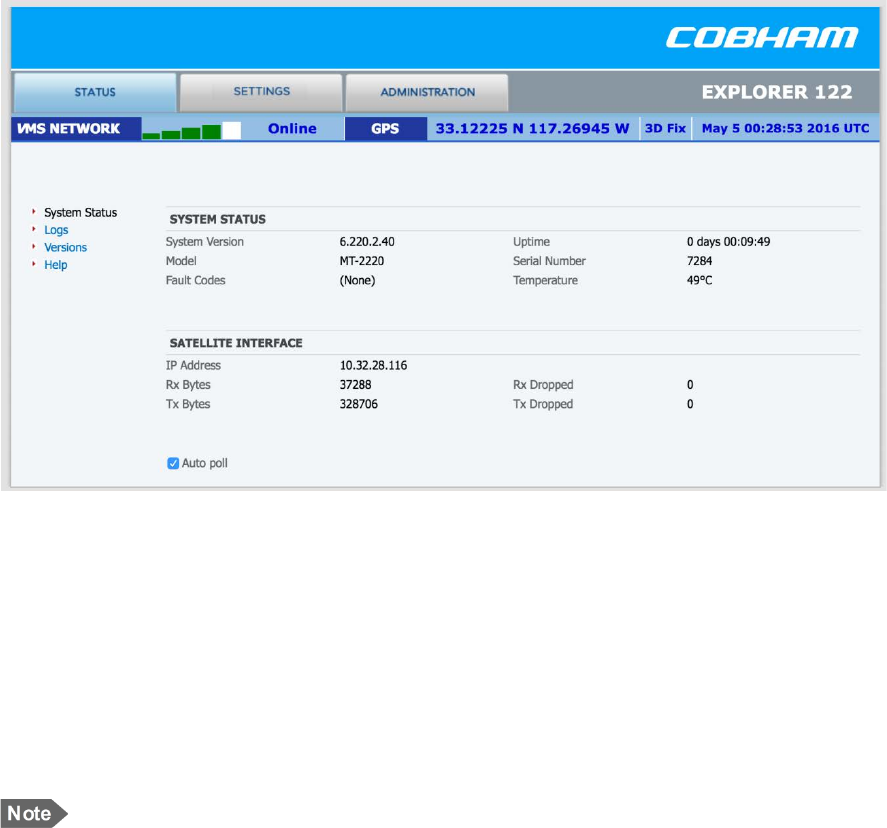
3.3 Status Tab
The status bar is included at the top of each page. It displays the current status of the
connection to the network and the latest GPS information (Figure 3-3).
Figure 3-3. Status Tab
3.3.1 Network
The received signal strength bars indicate the current received signal strength. The number
of bars that are green indicates the strength of the received signal for the modulation
scheme being used on the current received forward link. The more bars there are the
stronger the signal.
The status field shows the current state of the terminal on the network. Possible statuses are
shown below in:
NOTE: Signal strength will vary based on factors such as terminal location,
current data rate, and service plan.
EXPLORER 122
User Manual
98-150578-A 3-5
Table 3-1. Network Status
Status Field Status Meaning
Searching Terminal is searching for the
forward link
Acquired Terminal has acquired a
forward link
Registering Terminal is registering with
the network
Online Terminal logged in to the
network and ready for use
Offline Terminal logged off the
network
Re-Registering Terminal requesting to re-
login
3.3.2 GNSS
The GNSS fields show the current location. The location will only be valid when the terminal
has acquired enough GPS/GLONASS satellites for a valid lock.
3.3.3 System Status
System status displays general information about the current system (Table 3-2).
The Tx Bytes and Rx Bytes fields display the number of bytes sent and received over the
satellite. The Tx Dropped field displays the number of outgoing packets intended to be sent
over the satellite link but were dropped due to queue limitations, encryption failure or other
transmit errors. The Rx Dropped field displays the number of incoming packets that were
dropped due to space limitations, decryption failure, data integrity check failure or other
reception errors.
The Temperature field displays current temperature in Celsius within the terminal.
CAUTION: If you are experiencing issues with your terminal or observing
fault codes after reboot attempts, contact customer support.
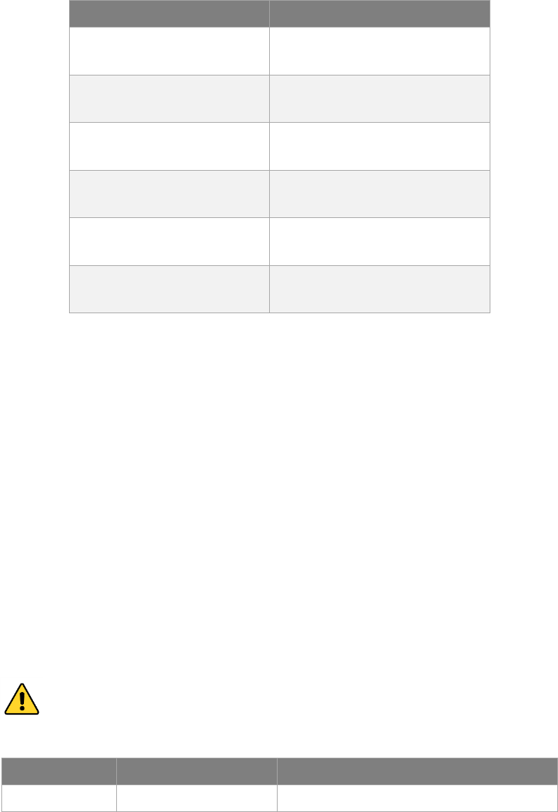
Table 3-2. System Status Fault Codes
Description Fault Code Action
General fault 0x01 - 0x53 Reboot the terminal
EXPLORER 122
User Manual
98-150578-A 3-6
Description Fault Code Action
Over temp
fault 0x61 - 0x63
Place terminal in environment less
than +70°C and power off until
terminal cools down
Under temp
fault 0x69 - 0x6B Place terminal in environment greater
than -40°C until terminal warms up
Power fault 0x70 or other Reboot the terminal
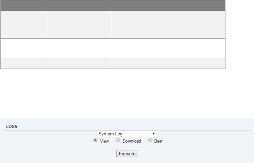
3.3.4 Logs
The Logs page allows the user to view or display system log files. All log files with the
exception of the NV (Non-Volatile) Log are volatile and are not maintained through reboots.
The NV Log contains high priority information that is saved through reboots (Figure 3-4).
Figure 3-4. Logs Pane
System Log
The System Log displays information about the operating system environment, including
drivers and devices.
Control Message Manager
The Control Message Manager processes network control messages and maintains the
terminal login state.
Web Administration
This log file contains information about actions performed by or when using the Web
Administration interface.
AT Server
The AT Server logs interactions between the internal AT command server and external AT
clients.
GPS
The GPS provides information regarding the internal GPS receiver and client.
NV Log
The NV logs high-priority terminal information that is maintained through reboots.
EXPLORER 122
User Manual
98-150578-A 3-7
3.3.5 Versions
This field displays the version number of each terminal software component.
3.4 Settings Tab
The settings tab lists terminal settings that can be modified by the user. A description of
each setting is listed below.
EXPLORER 122
User Manual
98-150578-A 3-8
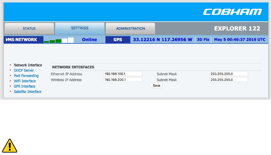
3.4.1 Network Interface
The Network Interface pane allows the user to set both the wired and wireless IP/subnet
mask for the terminal (Figure 3-5).
Figure 3-5. Network Interface Pane
Configure the Ethernet interface IP Address and Subnet Mask. These fields must be in dot
notation (a.b.c.d) and contain a valid IP address.
CAUTION: Modifying the IP Address and Subnet Masks can result in loss of
connectivity to the terminal. See Section 4 for more information on network
configuration settings and examples.
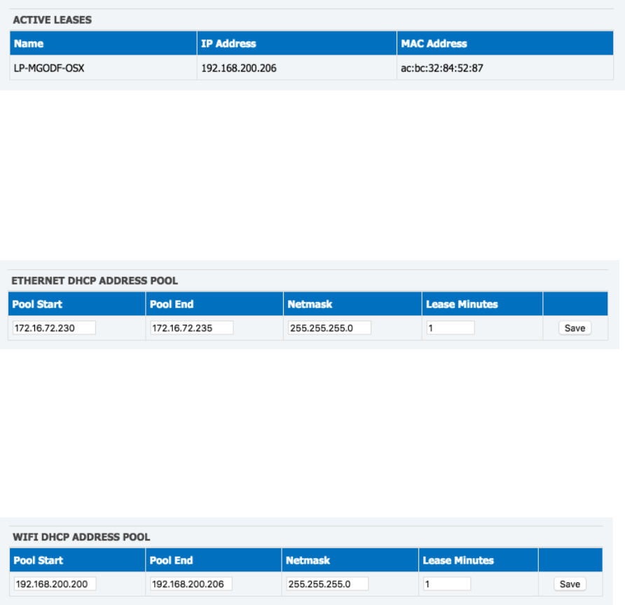
3.4.2 DHCP Server
There are two options for DHCP server configuration: dynamic and static (Figure 3-6).
Dynamic Assignments
The DHCP server can be configured with a pool of IP addresses that it will lease to clients.
The Pool Start and Pool End fields are set to the start and end IP addresses. The Netmask
field is set to the subnet mask that a client should use. Each of these fields must be a valid IP
address or subnet mask in dot notation (a.b.c.d).
The lease time is the time in minutes that a lease given to a client will be valid.
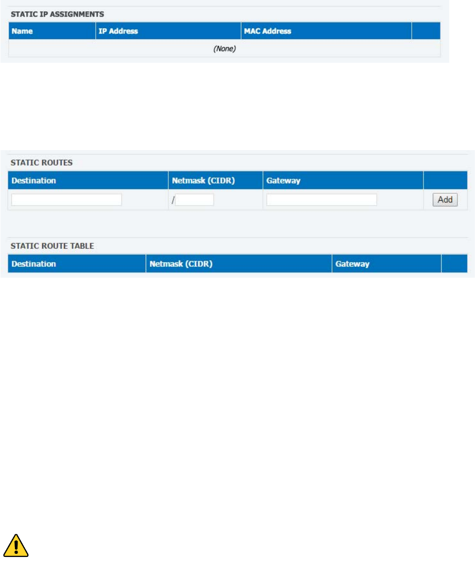
Static Assignments
The DHCP server can also be configured to provide a static IP address to a particular
network device. The network device is determined by its hardware MAC address. Each time
the DHCP server gets a request from a device that matches the MAC address the assigned IP
address will be given to the device.
The Name field is the hostname of the network device that will be assigned a static IP
address. This name must not contain any white space and should consist of alphanumeric
characters, hyphens or underscores. The MAC Address field is set to the MAC address of the
EXPLORER 122
User Manual
98-150578-A 3-9
network device. This field must be specified as follows: xx:xx:xx:xx:xx:xx, where xx is a two-
digit hexadecimal number. The IP Address field specifies the IP address to be assigned to the
network device with the corresponding MAC address. The IP address is specified in dot
notation (a.b.c.d).
Active Leases Table
Any currently active DHCP assignments are shown in the Active Leases and Static IP
Assignments in Figure 3-6.
Figure 3-6. DHCP Server - Active Leases
Ethernet DHCP Address Pool
The IP address allocation and lease time for the wired Ethernet dynamically-assigned DHCP
address pool is configured in Figure 3-7.
Figure 3-7. DHCP Server - Wired Ethernet DHCP Dynamic Address Pool
WLAN DHCP Address Pool
The IP address allocation and lease time for the WLAN dynamically-assigned DHCP address
pool is configured in Figure 3-8.
Figure 3-8. DHCP Server - WLAN DHCP Dynamic Address Pool
EXPLORER 122
User Manual
98-150578-A 3-10
Static IP Assignments
The IP address to MAC pairing for static IP assignments is contained in Figure 3-9.
Figure 3-9. DHCP Server - Static IP Assignments Table
Static Routes
Static routes are configured and listed in Figure 3-10
Figure 3-10. DHCP Server - Static Routes Tables
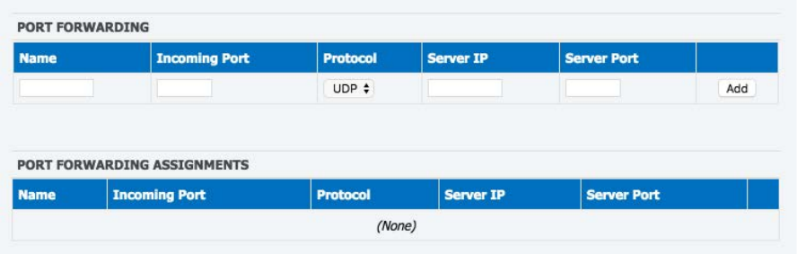
3.4.3 Port Forwarding
The terminal provides a network address translator (NAT) that creates a private network for
devices attached to the terminal. Devices behind the terminal NAT are invisible to any hosts
outside the terminal NAT.
The only way to access a device behind the terminal is either:
• Have the device behind the terminal initiate the connection
• Create a port forwarding assignment to the device in the terminal
Port forwarding allows incoming UDP or TCP packets destined for a specific port to be
forwarded to a network device (client or host) “behind” the terminal NAT. The incoming
packet will be forwarded to the destination port and IP address defined by the port
forwarding rule. Using port forwarding assigns the port being forwarded to a single host IP
address and excludes this port from being used by any other host.
CAUTION: Modifying port forwarding settings can result in loss of
connectivity to the network. See Section 4 for details on network
configuration and examples.
EXPLORER 122
User Manual
98-150578-A 3-11
Port Forward Assignments
Any currently active port forwarding assignments will be shown in the Port Forwarding
Assignments table (Figure 3-11).
To add a port forwarding configuration, enter the following information into the Port
Forwarding table:
1. Name – Set to the logical name of the service being forwarded. This name must not
contain any white space and should consist of alphanumeric characters, hyphens or
underscores.
2. Incoming Port – Set to the port number of the service to be forwarded, such as 21 for
FTP.
3. Protocol – Select between UDP/TCP/Both.
4. Server IP – Set to the IP address, in dot notation, of the host that the packets will be
forwarded to.
5. Server Port – Set to the port number on the Server IP that the packets will be sent to.
This port can be the same as the Incoming Port, but does not need to be.
6. When complete, click Add and the assignment will show up in the Port Forwarding
Assignments shown in Figure 3-11.
Figure 3-11. Port Forwarding Pane
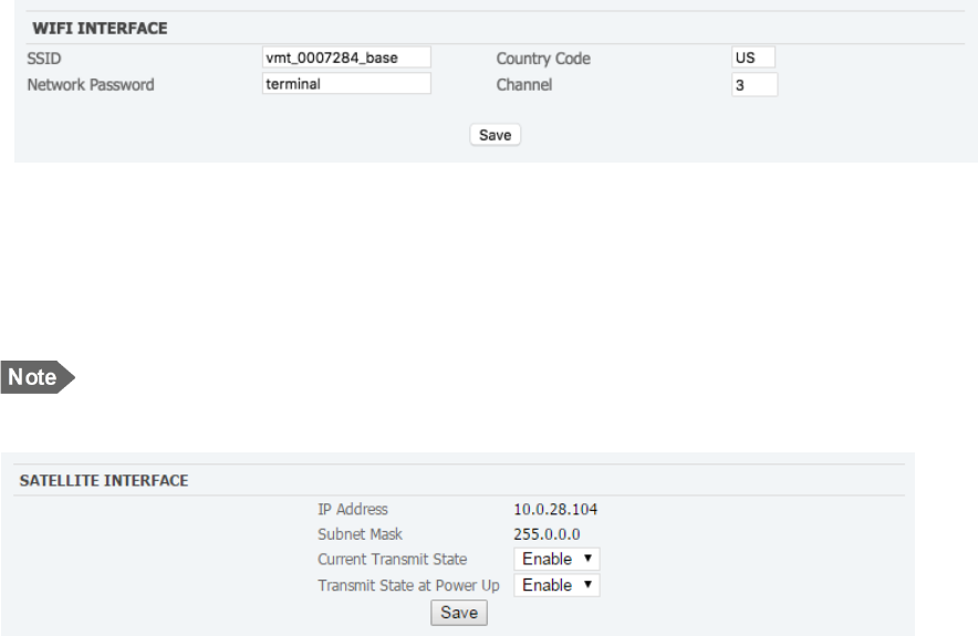
3.4.4 Wireless LAN Interface
The WiFi interface pane is used to configure your wireless access point interface for the
WLAN (Figure 3-12).
EXPLORER 122
User Manual
98-150578-A 3-12
To configure the access point settings set the following:
1. SSID – This is also known as your network name. Provide a unique SSID for the network.
The name must not exceed 32 characters.
2. Network Password – The terminal uses WPA2 encryption and requires a password. Use
this field to set the network password for the WLAN. The network password must be at
least 8 characters long but cannot be more than 63 characters.
3. Channel – Choose a transmit channel for your WLAN. Channels 1,6, and 11 are the
primary transmission channels used. If interference is experienced on those channels
then use one of the other channels.
4. Click Save.
Figure 3-12. WiFi Interface Pane
3.4.5 Satellite Interface
Configure the satellite interface transmit settings. These settings can be used to inhibit
terminal transmissions, both in real-time and at boot up (Figure 3-13).
NOTE: If terminal transmit is inhibited at boot up it will not be able to
communicate on the VMS network until transmit is enabled.
Figure 3-13. Satellite Interface Pane
The IP Address and Subnet Mask fields contain the external (Satellite Interface) address
configuration assigned to your terminal. These fields are assigned by your service provider.
Current Transmit State – Allows you to disable your terminal’s ability to transmit. For
normal operation, this should be set to Enabled. If disabled, your terminal will not be able to
send data over the satellite interface.
Transmit State at Power Up – Allows you to alter the power-up behavior so that the
terminal will not transmit when powered up. For normal operation, this should be set to
Enabled. If disabled, your terminal will not be able to send data over the satellite interface
upon power-up.
EXPLORER 122
User Manual
98-150578-A 3-13
3.5 Administration Tab
The Administration tab provides additional information and settings such as file uploads and
user administration.
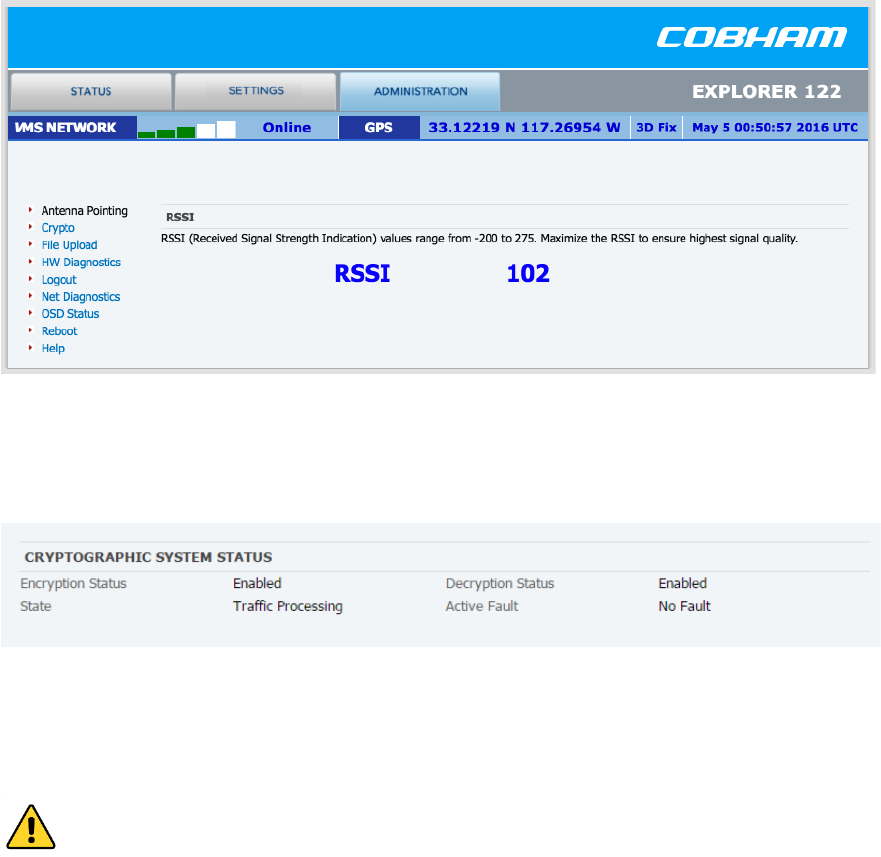
3.5.1 Antenna Pointing
The EXPLORER 122 Terminal does not require pointing. This pane reports the current receive
signal strength indicator (RSSI) of the terminals satellite network link (Figure 3-14).
Figure 3-14. Antenna Pointing Pane
3.5.2 Crypto
Displays status of the encryption engine used to provide data security (Figure 3-15).
Figure 3-15. Crypto Pane
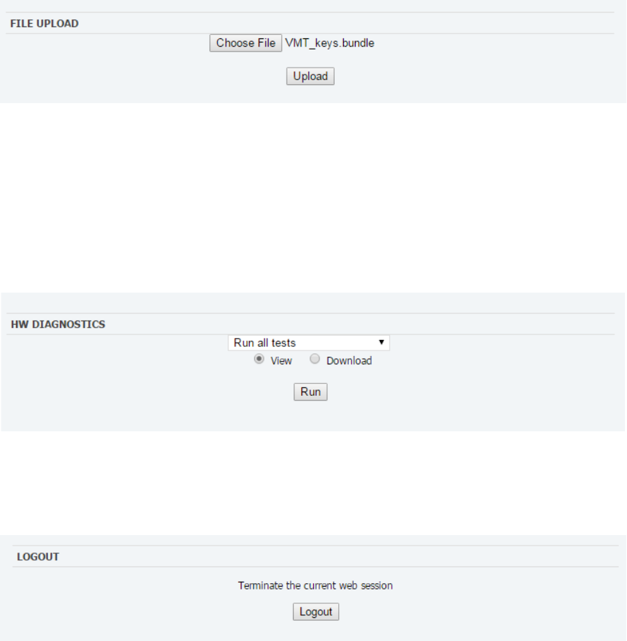
3.5.3 File Upload
The file upload function is used to upload terminal configuration files (Figure 3-16).
CAUTION: Improper file uploads can cause severe damage to the terminal.
File uploads should only be attempted if directed by customer or integrator
support.
EXPLORER 122
User Manual
98-150578-A 3-14
Figure 3-16. File Upload Pane
3.5.4 HW Diagnostics
Hardware diagnostics executes any or all of the terminal built-in tests. These diagnostics test
the basic functionality of the hardware components of the terminal. They can aid in finding
the cause of any hardware faults reported by the terminal. These tests should only be run
when the terminal is offline (Figure 3-17).
Figure 3-17. HW Diagnostics Pane
3.5.5 Logout
Initiates logout from the current webpage session (Figure 3-18).
Figure 3-18. Logout Pane
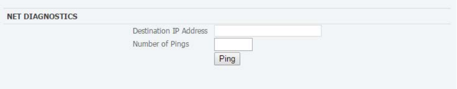
3.5.6 Net Diagnostics
Network diagnostics initiates pings to the destination IP address up to a maximum of 10
times. The results of the pings will be displayed (Figure 3-19).
EXPLORER 122
User Manual
98-150578-A 3-15
Figure 3-19. Net Diagnostics Pane
EXPLORER 122
User Manual
98-150578-A 3-16
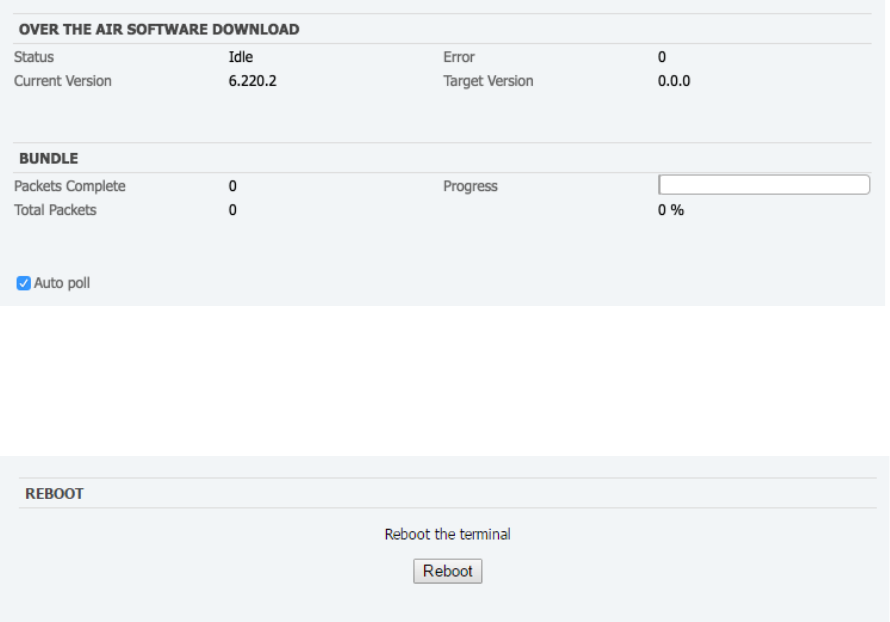
3.5.7 OSD Status
Over-the-Air Software Download (OSD) downloads new software into the terminal using the
satellite link instead of a local file upload. This page displays the current status of any
downloads in progress. OSD is a "trickle file download", using only idle capacity in the
satellite link sent in the background (Figure 3-20).
Figure 3-20. OSD Status Pane
3.5.8 Reboot
Initiates a reboot of the terminal (Figure 3-21).
Figure 3-21. Reboot Pane

EXPLORER 122
User Manual
98-150578-A 4-1
4 Troubleshooting, Maintenance, and
Technical Support
The EXPLORER 122 is designed to be very reliable and rugged. The terminal performs
automated self-tests and also provides for alarms, manual self-tests, and system resetting to
further evaluate the cause for, and possibly correct, any unexpected functionality. A further
list of problems that might arise, their possible causes, and potential remedies is provided in
section 5.2.
4.1 Self-Tests
The EXPLORER 122 has various self-tests to detect fault conditions. These tests are run on
start-up and periodically during the terminal operation. These tests can also be run manually
through the HW Diagnostics section 3.5.4. A list of these self-tests is provided in Table 5-1.
Table 4-1. Self-Tests
Self Tests Description
Ethernet Controller Verifies the operation of the Ethernet
controller chip
Information
Assurance
Verifies the operation of the data
encryption and decryption
McBSP1 Serial
Interface
Verifies the operation of the forward link
decoder
McBSP4 Serial
Interface
Verifies the ADC operation
FPGA Verifies that the FPGA has been
programmed correctly and the device
driver has been loaded
Temperature Sensor Reads the current temperature of the
board
NAND Flash Reads a known test pattern from flash
sector
DDR SDRAM Performs walking ones, walking zeros, and
address line RAM tests
MIMO Verifies the RF transceiver’s device id

EXPLORER 122
User Manual
98-150578-A 4-2
Self Tests Description
ENSM Verifies that RF transceiver’s operational
state is FDD
Real Time Clock Verifies the real time clock’s device id
Rx Synthesizer Verifies that the RX PLL is locked
Tx Synthesizer Verifies that the TX PLL is locked
Display Ethernet
Status
Displays the number of Ethernet packet
received and sent and the link status
Display Current OBIT
results
Displays result of the current online BIT
tests
Display POST Results Displays the result of the power-on self-
tests
4.2 Troubleshooting Guide
Faults may be detected by visual observation or by the built-in test (BIT). Problems
uncovered during preventive maintenance, or while the terminal is in service, their possible
cause, and recommended corrective action(s) are described in Table 5-2.
Table 4-2. Troubleshooting Guide
Problem/Observation Possible Cause Corrective Action
Cannot access terminal
web server
Terminal not powered on
Incorrect IP address
Cable is not plugged in
correctly
Default Ethernet IP address is
192.168.100.1
Default WLAN IP address is
192.168.200.1
Verify that cable is connected
to user device LAN port.
Verify the WLAN settings are
correct
Terminal not responding
to web server interface
Software error Power Cycle Terminal

EXPLORER 122
User Manual
98-150578-A 4-3
Problem/Observation Possible Cause Corrective Action
Web server shows no
position fix
Terminal position is unknown,
GNSS signal is weak
Provide terminal with
unobstructed view of sky as
much as possible. Try to point
terminal straight upward to
receive GPS fix, then repoint
terminal toward L-band
satellite
Web server status shows
terminal does not exit
searching mode
View toward satellite is
blocked
Ensure that no object is in
front of antenna
WLAN connection cannot
be established
Your device is too far from
terminal
Mover closer to the terminal
Terminal cannot login or
does not exit searching
mode
No signal or weak signal
Interference
Provide terminal with
unobstructed view of sky as
much as possible. Reposition
the terminal as necessary.
Position terminal away from
other antennas

EXPLORER 122
User Manual
98-150578-A 4-4
Faults may be visually observed as error codes on the Web MMI Status page as seen in Table
5-3. Web MMI Status.
Table 4-3. Web MMI Status
Fault Code
Description
Recommended Action
0x01 - 0x53
General fault
Reboot the terminal
0x61 - 0x63 Over temp fault Place terminal in
environment less than
+70°C and power off until
terminal cools down
0x69 - 0x6B Under temp fault Place terminal in
environment greater than -
40°C until terminal warms
up
0x70 or other Power fault Reboot the terminal
4.3 Preventative Maintenance
Preventative maintenance is the systematic, scheduled care and inspection of equipment to
prevent equipment failure and to reduce downtime. The primary preventative maintenance
for the EXPLORER 122 Terminal is to keep the equipment clean. Use a soft brush, moist
sponge, and a clean cloth for this purpose. The radome should be visually inspected for any
attached substances, which could potentially obstruct functionality (e.g., mud on the
radome).
In addition, to ensure proper functionality and full operating potential of EXPLORER 122
Terminal capabilities, the unit should be visually inspected for cracks, corrosion, and loose
mating connector.
4.4 Warranty
For warranty information and repairs, please contact your service provider.
4.5 Serviceable Parts
The EXPLORER 122 Terminal contains no user-serviceable parts.

EXPLORER 122
User Manual
98-150578-A 4-5
4.6 Customer Support
Should your Cobham SATCOM product fail, please contact your dealer or installer, or the
nearest Cobham SATCOM partner. You will find the partner details
on www.cobham.com/satcom where you also find the Cobham SATCOM Self Service Center
web-portal, which may help you solve the problem. Your dealer, installer or Cobham
SATCOM partner will assist you whether the need is user training, technical support,
arranging on-site repair or sending the product for repair. Your dealer, installer or Cobham
SATCOM partner will also take care of any warranty issue.
EXPLORER 122
User Manual
98-150578-A A-1
Appendix A - Power/Ethernet Cable Assembly Instruction
This section provides guidelines for the Value-Added Resellers or end-user to assemble the
power/Ethernet cables. The solder cup connector kit ships with the terminal.
A.1 Required Tools
The following tools are required to assemble the power/Ethernet cable:
• Utility knife or similar
• 18-26 AWG wire stripper
• Diagonal cutters
• Long-nose pliers
• Soldering iron and solder
A.2 Connector Pinout Information
The figures below show the connector and cable wiring diagram.
P1 Connector
P2 Connector
A.3 Cable Specification
The cable selection for this application is influenced by three main principles: current
capacity, outdoor application and shielding.
EXPLORER 122
User Manual
98-150578-A A-2
The operating input voltage range for the terminal is 10 to 30 VDC and draws a maximum of
4.8 amperes. If the application requires an extended cable length, it is necessary to calculate
the cable voltage drop to determine if the terminal is able to receive the minimum 10 volts
for operation. 18 AWG wire is recommended for both power and ground wires.
Exposure to outdoor elements can degrade the insulation of the cable and allow moisture to
penetrate the conductor and subsequently degrade the copper conductor. It’s highly
recommended that the cable chosen shall be able to withstand UV rays.
Cable shielding is a critical design element over long distance. The cable selection can
adversely be affected by EMI/RFI/ESI. The cable carries both power and Ethernet data. The
data lines should be twisted pair and shielded.
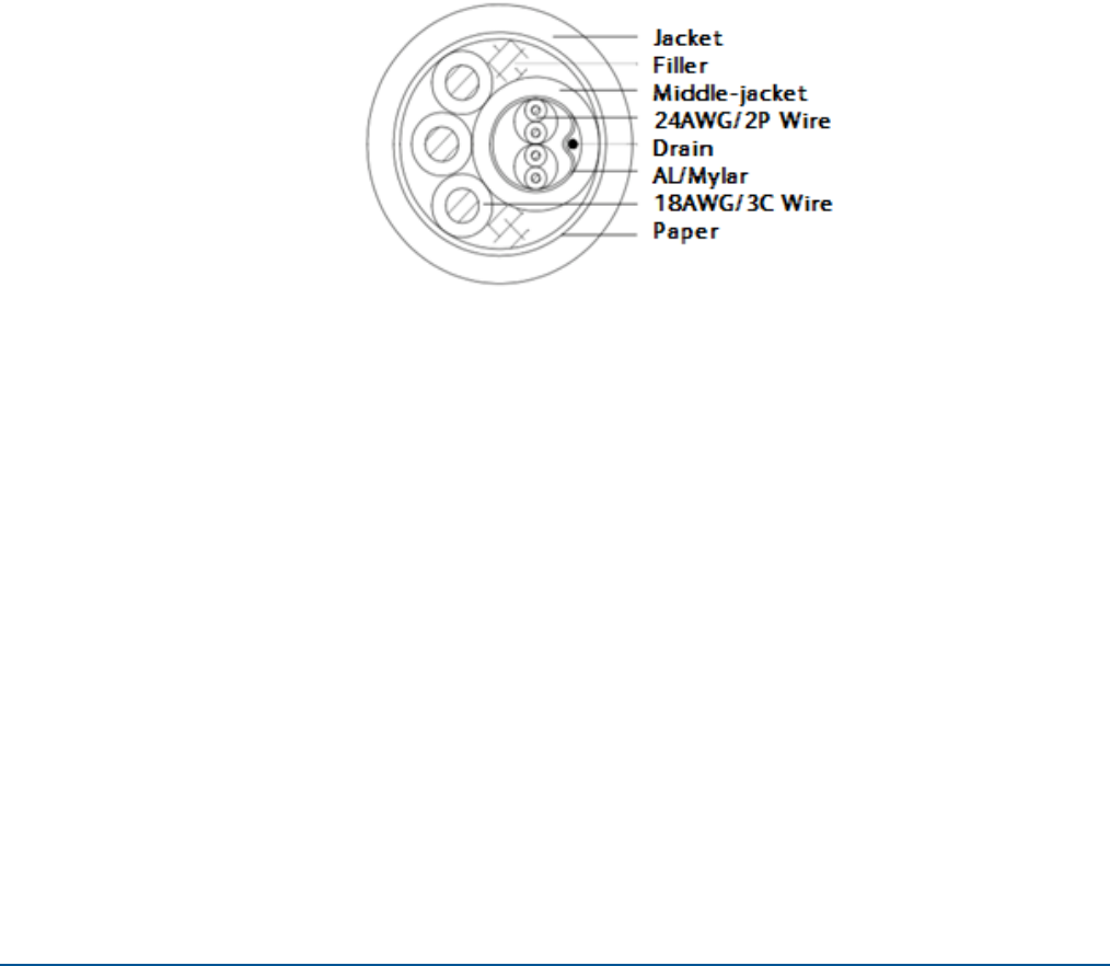
The recommended cable composition is described in the picture below. The overall cable
diameter should be less than 9.50 mm in order to fit in the connector backshell.

EXPLORER 122
User Manual
98-150578-A A-3
A.3.1 Physical Characteristics
Parameter
Conductor
Construction
24AWG/2P
18AWG/3C
Insulation
Nom. Thickness
Min. Thickness
OD
HDPE
0.20 mm
0.15 mm
1.00
±
0.10
PVC
0.38 mm
0.33 mm
2.00
±
0 0.15
Assemble
Coating
Drain Wire
Coating
2P
Mylar
Tinned Copper 7/0.20
Al/Mylar
Middle-Jacket
Nom. Thickness
Min. Thickness
PVC
0.40 mm
0.30 mm
Outer Jacket
Nom. Thickness
Min. Thickness
Diameter
PVC (UV resistance -40
°
C to +105
°
C)
1.10
0.84
9.5 +0/-0.40
Color
Wire
Jacket
Pair 1 green+white/green
Pair 2 orange+white/orange 3C: black, red, blue
Black
A.3.2 Mechanical Characteristics
Storage Temperature
-40
°
C To +105
°
C
Operating Temperature
-25
°
C To +105
°
C
Tensile Strength (insulation & jacket)
Before
1.05 Kgf/mm2
Elongation
Aging
100%
Aging Condition
136 ±2°C x 168 hours
Tensile Strength
After
>= 70% of unaged
Elongation
Aging
>=65% of unaged
A.3.3 Agency Compliance
Standard
UL758/UL1581
Temperature Rating
-40
°
C To +105
°
C
Rated Voltage
300V
Flame Test
VW-1
AWM Specifications
UL Style 2464
EXPLORER 122
User Manual
98-150578-A A-4
Withstanding Voltage
1.5 KV min
Spark Voltage
3 KV
A.3.4 Electrical Characteristics
Max. Conductor DC Resistance @20
°
C
87.6 Ω/km (24AWG) / 23.2 Ω/km (18AWG)
Max DC Resistance Unbalanced @20
°
C
5%
Maximum Pair-to-Pair Ground Capacitance
Unbalanced 330 pF / 100 m
Characteristic Impedance (1-100 MHz)
100
±
15 Ω
Frequency
100 MHz
Attenuation (Insertion Loss)*
24 dB
Characteristic Impedance
100 ± 15 Ω
NEXT*
30.1 dB
PS-NEXT*
27.1 dB
ELFEXT*
17.4 dB
PS-ELFEXT*
14.4 dB
Return Loss*
20.1 dB / 100 m
Delay Skew*
45 ns / 100 m
*Min. at 100 MHz
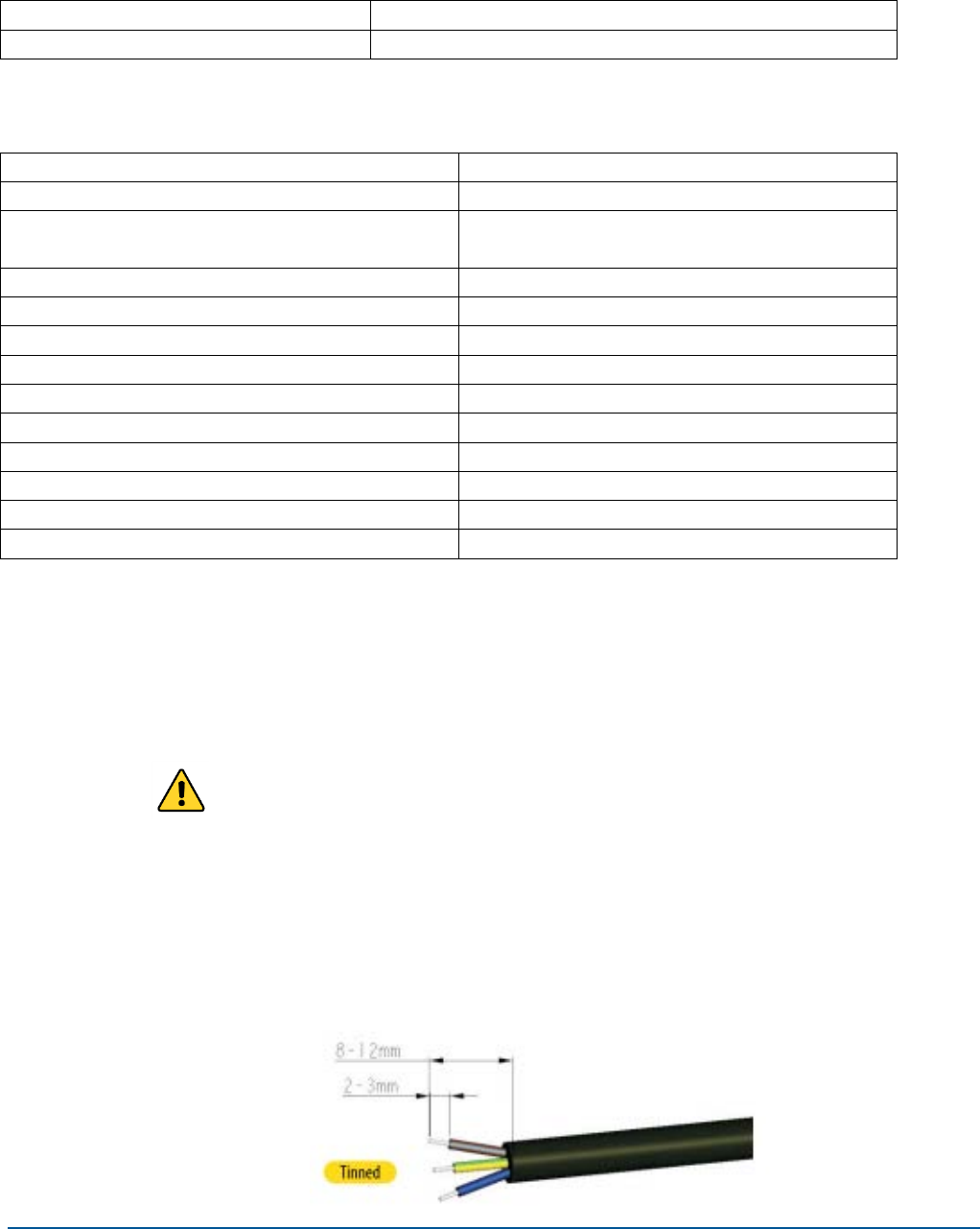
A.4 Cable Assembly Steps
Use a utility knife to remove 12mm of the outer jacket of the cable and use diagonal cutters
to remove any shielding as shown in Figure A-1. Carefully remove 2-3mm of insulation from
the wires using a wire stripper. Avoid nicking the center conductor as you strip the insulation
from the wire. Ensure that the drain wire is at the same length as the other wires.
WARNING: make sure DC power is not connected during cable
assembly

EXPLORER 122
User Manual
98-150578-A A-5
Figure A-1. Cable Assembly Preparation
EXPLORER 122
User Manual
98-150578-A A-6
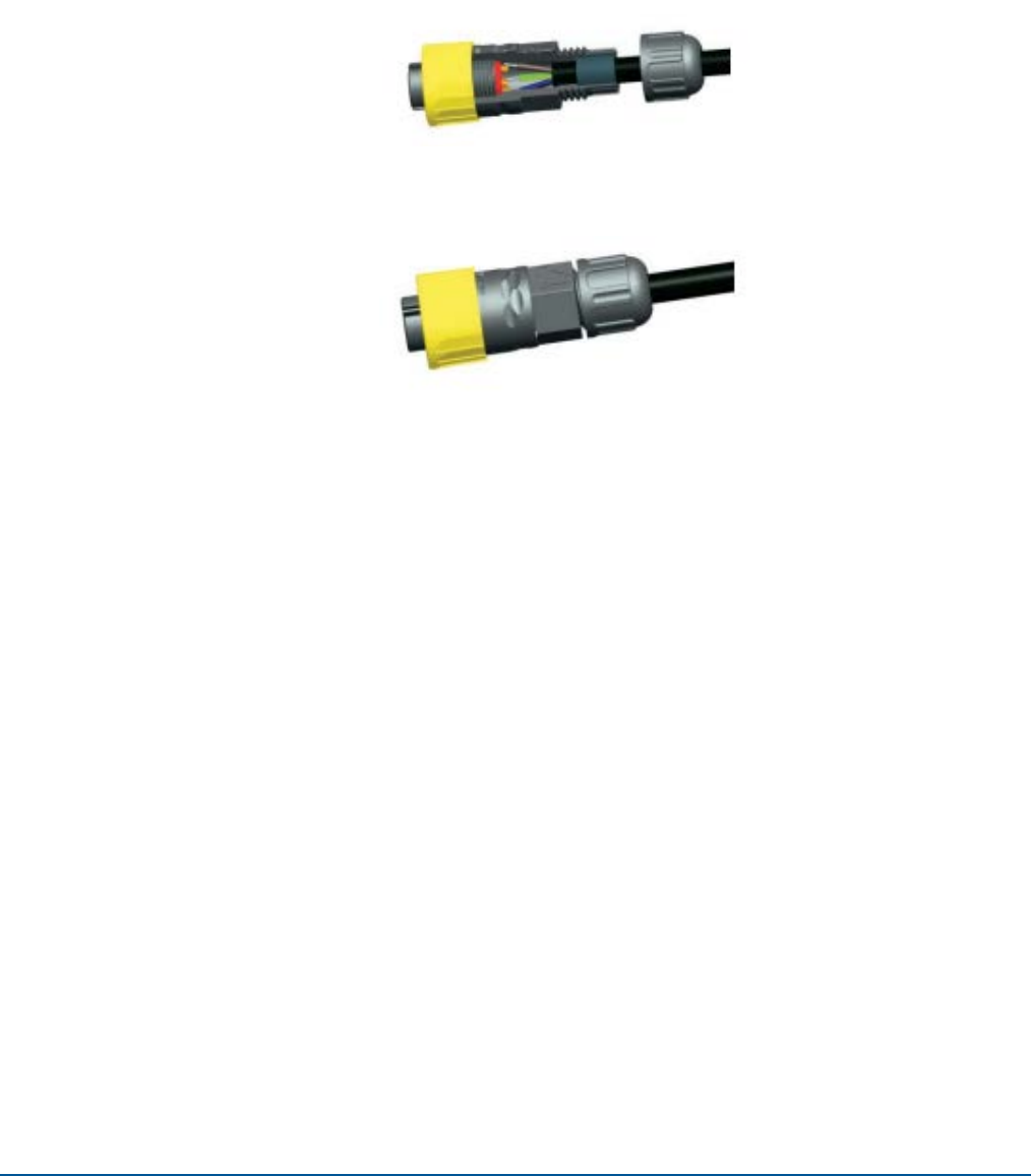
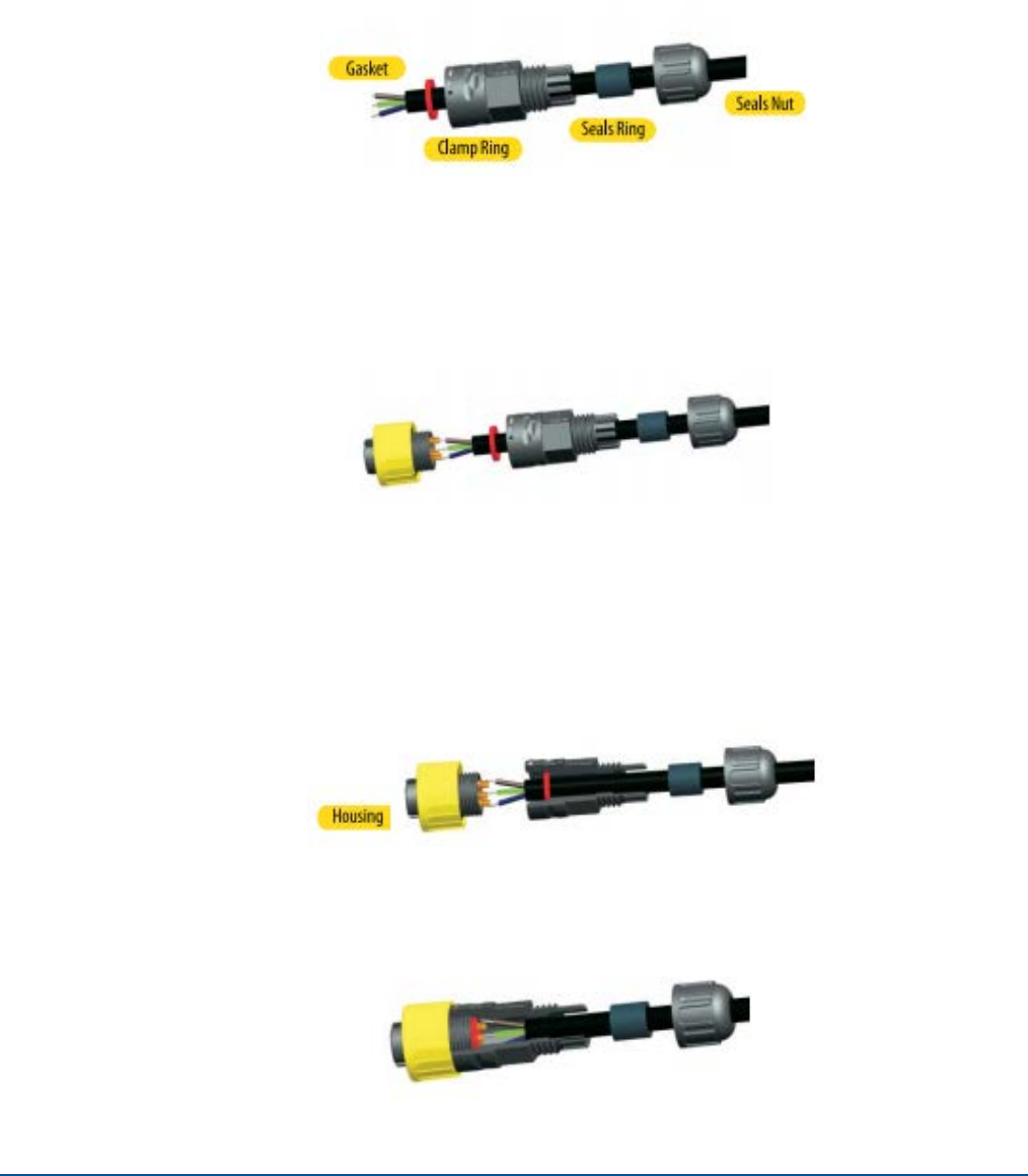
The bare ends on the stripped wire may require twisting to prevent fraying when the
connector parts are slid over the cable. Slide the items over the cable in sequential order as
shown in Figure A-2. Observe that the seal ring and red gasket are present.
Figure A-2. Connector Part Description
Apply a thin coat of solder for tinning on the bare wires and on the connector socket
contacts in preparation of soldering the wires to the end connector contacts as shown in
Figure A-3. Solder the tinned wires to the socket contacts.
Figure A-3. Cable Assembly - Step 1
Assemble the gasket into the clamp ring. The gasket is directional and the flat surface should
be installed on the housing side as shown in Figure A-4.
Figure A-4. Cable Assembly - Step 2
Assemble the clamp ring to the housing as shown in Figure A-5.
Figure A-5. Cable Assembly - Step 3