Viconics Electronics VT WIRELESS THERMOSTAT User Manual USERS MANUAL
Viconics Electronics Inc. WIRELESS THERMOSTAT USERS MANUAL
UserManual.wiki
>
Viconics Electronics
>
VT User Manual
USERS MANUAL
Navigation menu
Upload a User Manual
Namespaces
Wiki Guide
HTML
PDF
Info
Views
User Manual
Discussion / Help
Navigation
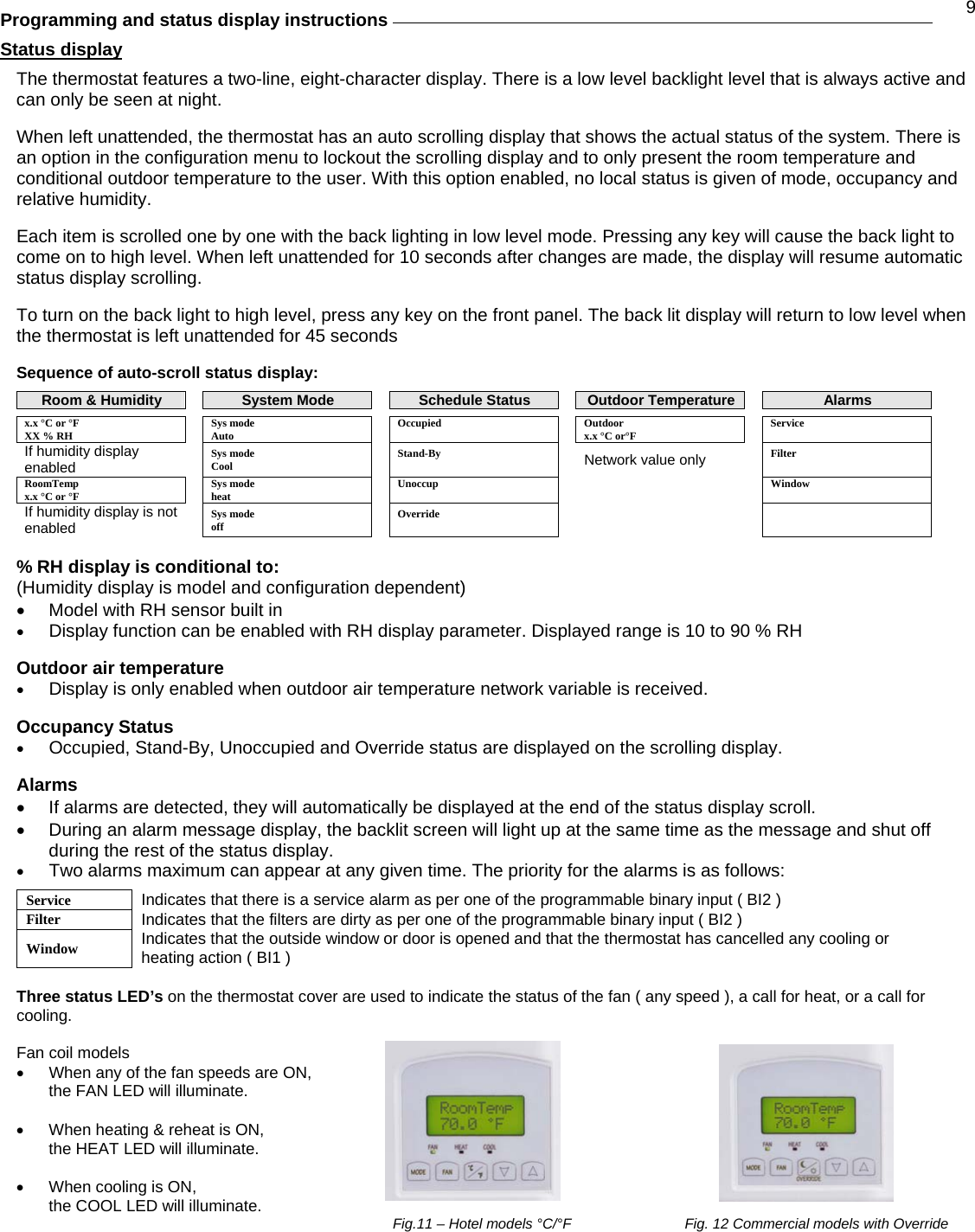
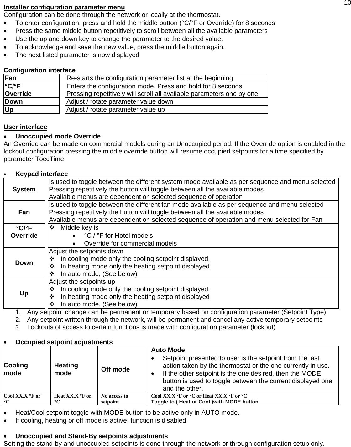
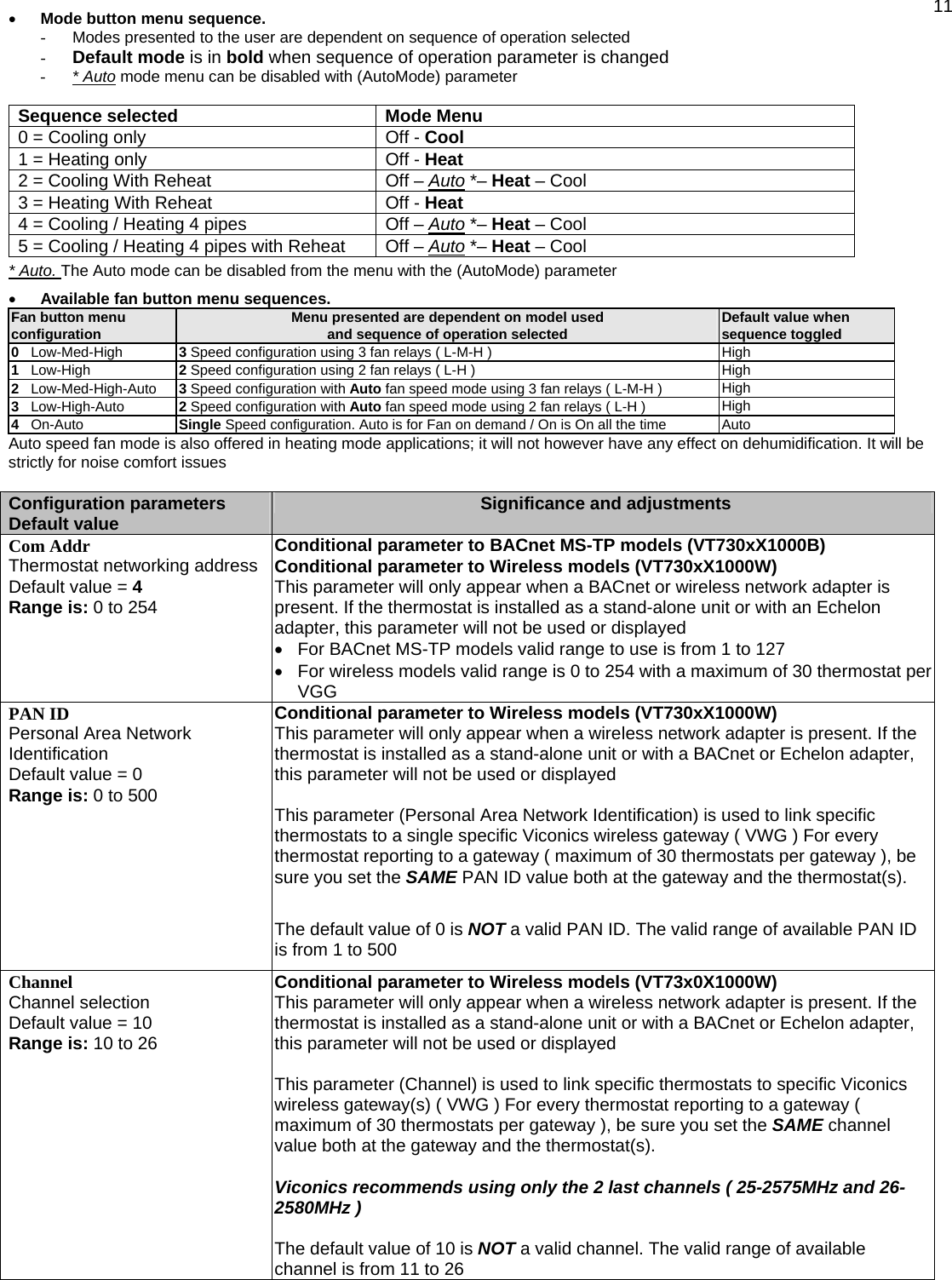
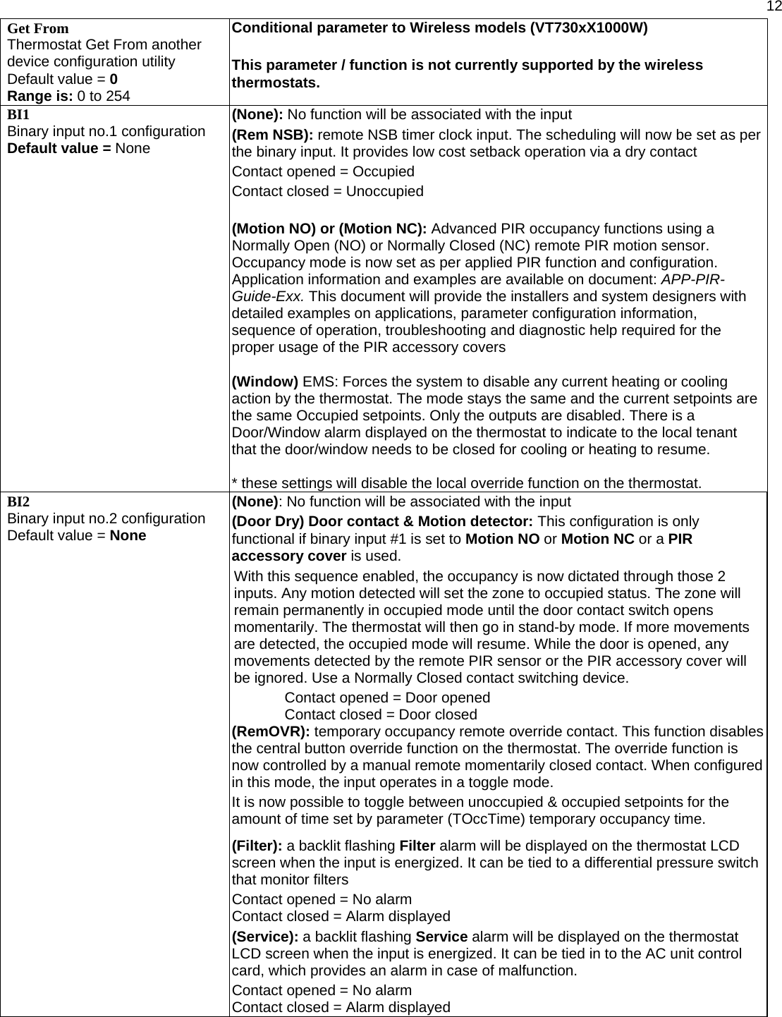
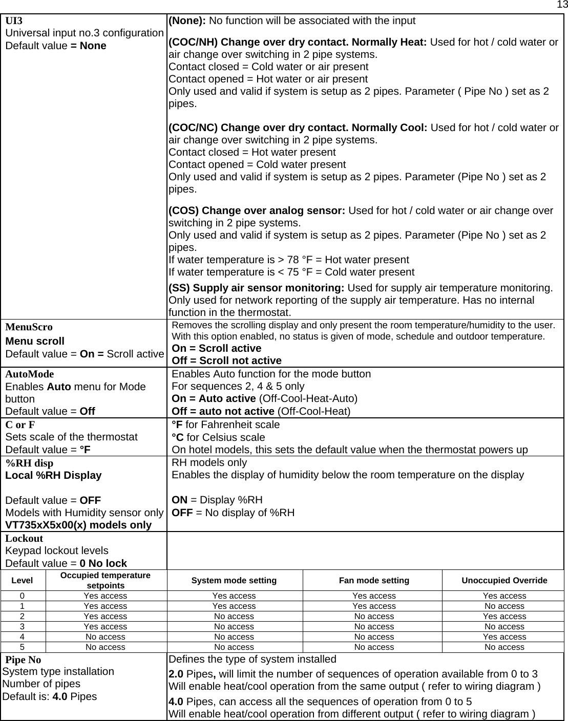
![17 Specifications Thermostat power requirements: 19-30 Vac 50 or 60 Hz; 2 VA Class 2 Operating conditions: 0 °C to 50 °C ( 32 °F to 122 °F ) 0% to 95% R.H. non-condensing Storage conditions: -30 °C to 50 °C ( -22 °F to 122 °F ) 0% to 95% R.H. non-condensing Temperature sensor: Local 10 K NTC thermistor Temperate sensor resolution: ± 0.1 °C ( ± 0.2 °F ) Temperature control accuracy: ± 0.5 ° C ( ± 0.9 °F ) @ 21 °C ( 70 °F ) typical calibrated Humidity sensor and calibration: Single point calibrated bulk polymer type sensor Humidity sensor precision: Reading range from 10-90 % R.H. non-condensing 10 to 20% precision is 10% 20% to 80% precision is 5% 80% to 90% precision is 10% Humidity sensor stability Less than 1.0 % yearly (typical drift) Dehumidification setpoint range: 30% to 95% R.H. Occ, Stand-By and Unocc cooling setpoint range: 12.0 to 37.5 °C ( 54 to 100 °F ) Occ, Stand-By and Unocc heating setpoint range: 4.5 °C to 32 °C ( 40 °F to 90 °F ) Room and outdoor air temperature display range -40 °C to 50 °C ( -40 °F to 122 °F ) Proportional band for room temperature control: Cooling & Heating: 1.8°C ( 3.2°F ) Binary inputs: Dry contact across terminal BI1, BI2 & UI3 to Scom Contact output rating: Fan relay output: 30 Vac, 1 Amp. Maximum, 3 Amp. in-rush Valve triac output: 30 Vac, 1 Amp. Maximum, 3 Amp. in-rush Valve analog: 0 to 10 Vdc into 2KΩ resistance min. Wire gauge 18 gauge maximum, 22 gauge recommended Dimensions: 4.94” x 3.38” x 1.13” Approximate shipping weight: 0.75 lb ( 0.34 kg ) Agency Approvals all models: UL: UL 873 (US) and CSA C22.2 No. 24 (Canada), File E27734 with CCN XAPX (US) and XAPX7 (Canada) Industry Canada: ICES-003 (Canada) Agency Approvals Stand-Alone, BACnet & LON models FCC: Compliant to CFR 47, Part 15, Subpart B, Class A (US) CE: EMC Directive 89/336/EEC (Europe Union) C-Tick: AS/NZS CISPR 22 Compliant (Australia / New Zealand) Supplier Code Number N10696 Agency Approvals Wireless models FCC: Compliant to: Part 15, Subpart C THIS DEVICE COMPLIES WITH PART 15 OF THE FCC RULES. OPERATION IS SUBJECT TO THE FOLLOWING TWO CONDITIONS: (1) THIS DEVICE MAY NOT CAUSE HARMFUL INTERFERENCE, AND (2) THIS DEVICE MUST ACCEPT ANY INTERFERENCE RECEIVED, INCLUDING INTERFERENCE THAT MAY CAUSE UNDESIRED OPERATION. Drawing & Dimensions 3.38" [86 mm]1.13" [29 mm]4.94" [125 mm] Fig.13 – Thermostat dimensions Important Notice All VT7300 series controls are for use as operating controls only and are not safety devices. These instruments have undergone rigorous tests and verifications prior to shipment to ensure proper and reliable operation in the field. Whenever a control failure could lead to personal injury and/or loss of property, it becomes the responsibility of the user / installer / electrical system designer to incorporate safety devices ( such as relays, flow switch, thermal protections, etc…) and/or alarm system to protect the entire system against such catastrophic failures. Tampering of the devices or miss application of the device will void warranty.](https://usermanual.wiki/Viconics-Electronics/VT/User-Guide-956885-Page-17.png)