Viconics Electronics VT WIRELESS THERMOSTAT User Manual USERS MANUAL
Viconics Electronics Inc. WIRELESS THERMOSTAT USERS MANUAL
USERS MANUAL
PIR Ready VT7300 Series
24 Vac Low Voltage Fan Coil Thermostats
For Commercial and Lodging HVAC Applications
(Issue Date: June 16, 2008 – 028-0183_R3)
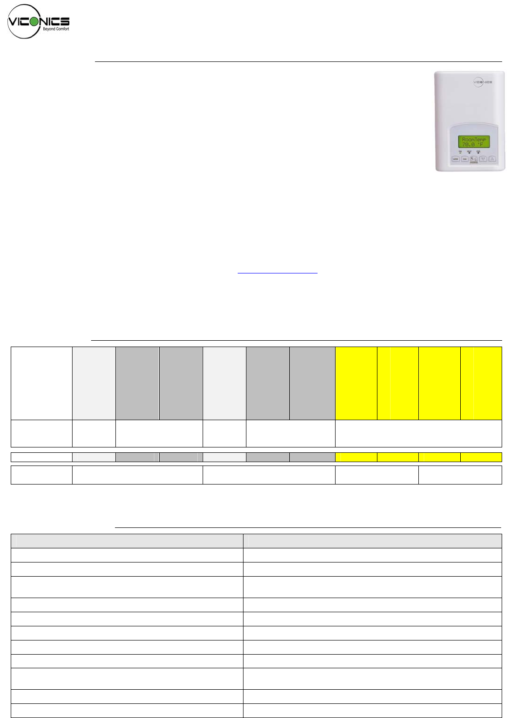
Product overview
The VT7300 PI thermostat family is specifically designed for fan coil control. The product
features a backlit LCD display with dedicated function menu buttons for simple operation.
Accurate temperature control is achieved due to the product’s PI proportional control
algorithm, which virtually eliminates temperature offset associated with traditional,
differential-based thermostats.
Models are available for On/Off, 3 point floating and analog 0 to 10 Vdc control and can
control up to three fan speed. Three additional inputs are also provided for monitoring and /
or various advanced functions.
All models feature configurable System and Fan button functions to meet all possible applications. They all contain
an SPST auxiliary switch that can be used to control lighting or auxiliary reheat.
The thermostats are also compatible with the new Viconics PIR cover accessories. Thermostats equipped with a
PIR cover provide advanced active occupancy logic, which will automatically switch occupancy levels from
Occupied to Stand-By and Unoccupied as required by local activity being present or not. This advanced
occupancy functionality provides advantageous energy savings during occupied hours without sacrificing occupant
comfort. All thermostats can be ordered with or without a factory installed PIR cover ( see ordering notes below ).
The additional following documents are available at: www.viconics.com
• PIR application information and examples, are available on document: APP-PIR-Guide-Exx
• PIR cover installation information is available on document: PIR Cover Installation-Exx
• Information on the LON models (VT73xxX5000E), is available on document ITG-VT7300-PIR-LON-Exx
• Information on the BACnet models (VT73xxX5000B), is available on document ITG-VT7300-PIR-BAC-Exx
• Information on the Wireless models (VT73xxX5000W), is available on documents: ITG-VWG-40-BAC-Exx and LIT-VWG-40-SETUP-Exx
Models available
Viconics
Part
Numbers
VT7300A5000(X)
VT7300C5000(X)
VT7350C5000(X)
VT7305A5000(X)
VT7305C5000(X)
VT7355C5000(X)
VT7300F5000(X)
VT7350F5000(X)
VT7305F5000(X)
VT7355F5000(X)
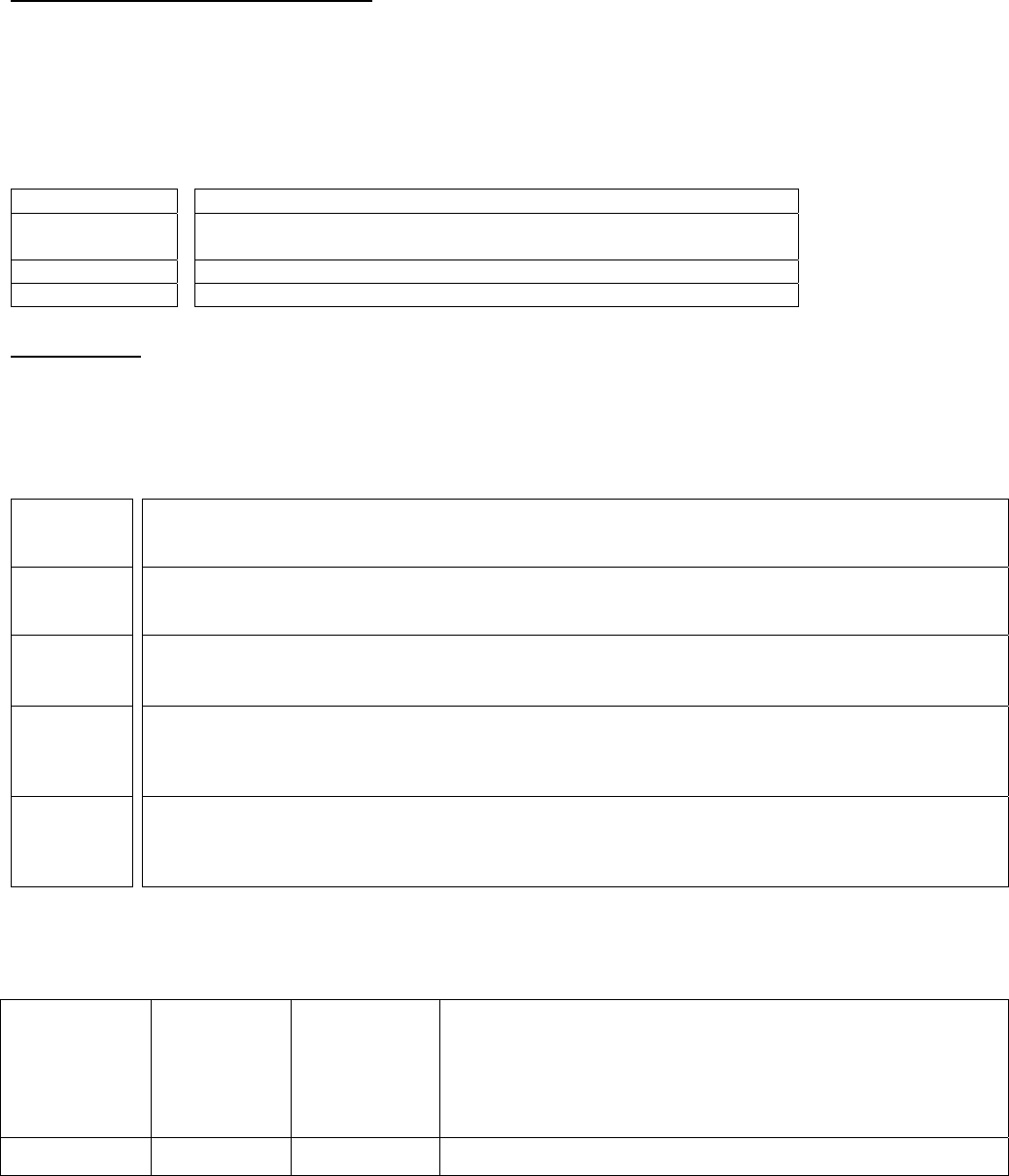
Application 2 & 4
Pipes
On/Off
2 & 4 Pipes
Floating & On/Off
2 & 4
Pipes
On/Off
2 & 4 Pipes
Floating & On/Off 2 & 4 Pipes
Analog 0-10 Vdc
RH sensor No No Yes No No Yes No Yes No Yes
Market Commercial / Institution Hotels / Lodging Commercial /
Institution Hotels / Lodging
Ordering Information Notes:
- (X) model number represents available communication options: X=none for Stand-alone, X=B for BACnet MS-TP, X=E for Echelon and X=W for Wireless
- Thermostats can be ordered with a factory installed PIR cover. Please use (5500) extension instead of the (5000) only extension.: Ex. VT7300C5500E.
- Thermostats ordered without a PIR cover can be retrofitted with a separate PIR accessory cover afterwards when required
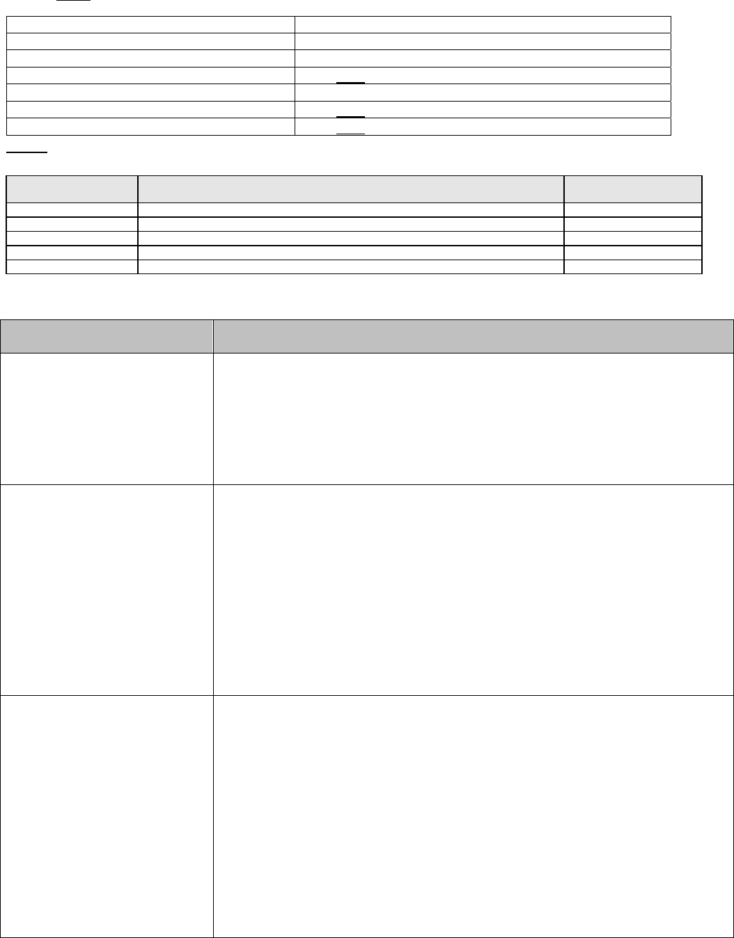
Features and benefits
Features Benefits
• Models available with internal humidity sensing ⇒ Increased occupant comfort through dehumidification
• Advanced occupancy functions ⇒ Through the network or smart local occupancy sensing
• Ready for PIR accessory cover ⇒ Fully integrated advanced occupancy functionality with a
PIR accessory cover
• 3 configurable inputs ⇒ Adds functionality
• Configurable sequences of operation ⇒ Single model meets more applications
• Configurable fan functions button ⇒ Meets more applications with a single model
• Unique configuration setup utility ⇒ Minimizes parameter tampering
• Multi level lockable keypad ⇒ Tamper proof, no need for thermostat guards
• Auto Fan speed mode ⇒ Increased occupant comfort in cooling mode by reducing
humidity and offer less fan noise in all mode of operation
• Available for 24 Vac On/Off, Floating or Analog control ⇒ Meet advanced applications requirements
• Auxiliary output ⇒ Can be used for lighting or reheat
028-0183 R3_LIT-VT7300-PIR-E03.doc www.viconics.com / sales@viconics.com

2
Programmable BI/UI inputs overview
Binary input #1 can be configured for the following
functions:
1. (None): No function will be associated with the
input
2. (Rem NSB): remote NSB timer clock input. The
scheduling will now be set as per the binary input.
It provides low cost setback operation via a dry
contact
• Contact opened = Occupied
• Contact closed = Unoccupied
3. (Motion NO) and (Motion NC): Advanced PIR
occupancy functions using a Normally Open (NO)
or Normally Closed (NC) remote PIR motion
sensor. Occupancy mode is now set as per applied
PIR function and configuration. Application
information and examples, are available on
document: APP-PIR-Guide-Exx. This document will
provide the installers and system designers with
detailed examples on applications, parameter
configuration information, sequence of operation,
troubleshooting and diagnostic help required for the
proper usage of the PIR accessory covers
4. (Window) EMS: Forces the system to disable any
current heating or cooling action by the thermostat.
The mode stays the same and the current setpoints
are the same Occupied setpoints. Only the outputs
are disabled. There is a Door/Window alarm
displayed on the thermostat to indicate to the local
tenant that the door/window needs to be closed for
cooling or heating to resume. Use NC contact.
• Contact opened = System disabled with local
Window alarm
• Contact closed = System enabled
Binary input #2 can be configured for the following
functions:
1. (None): No function will be associated with the
input
2. (Door Dry) Door contact & Motion detector:
This configuration is only functional if binary input
#1 is set to Motion NO or Motion NC or a PIR
accessory cover is used.
With this sequence enabled, the occupancy is now
dictated through those 2 inputs. Any motion
detected will set the zone to occupied status. The
zone will remain permanently in occupied mode
until the door contact switch opens momentarily.
The thermostat will then go in stand-by mode. If
more movements are detected, the occupied mode
will resume. While the door is opened, any
movements detected by the remote PIR sensor or
the PIR accessory cover will be ignored. Use a
Normally Closed contact switching device.
• Contact opened = Door opened
• Contact closed = Door closed
3. (RemOVR): temporary occupancy remote override
contact. This function disables the central button
override function on the thermostat. The override
function is now controlled by a manual remote
momentarily closed contact. When configured in
this mode, the input operates in a toggle mode.
It is now possible to toggle between unoccupied &
occupied setpoints for the amount of time set by
parameter (TOccTime) temporary occupancy time.
4. (Filter): a backlit flashing Filter alarm will be
displayed on the thermostat LCD screen when the
input is energized. It can be tied to a differential
pressure switch that monitor filters
• Contact opened = No alarm
• Contact closed = Alarm displayed
5. (Service): a backlit flashing Service alarm will be
displayed on the thermostat LCD screen when the
input is energized. It can be tied in to the AC unit
control card, which provides an alarm in case of
malfunction.
• Contact opened = No alarm
• Contact closed = Alarm displayed
Universal input #3 can be configured for the
following functions:
1. (None): No function will be associated with the
input
2. (COC/NH) Change over dry contact. Normally
Heat: Used for hot / cold water change over
switching in 2 pipe systems.
• Contact closed = Cold water present
• Contact opened = Hot water present
Only used and valid if system is setup as 2 pipes.
Parameter ( Pipe No ) set as 2 pipes.
3. (COC/NC) Change over dry contact. Normally
Cool: Used for hot / cold water or air change over
switching in 2 pipe systems.
• Contact closed = Hot water present
• Contact opened = Cold water present
Only used and valid if system is setup as 2 pipes.
Parameter ( Pipe No ) set as 2 pipes.
4. (COS) Change over analog sensor: Used for hot
/ cold water or air change over switching in 2 pipe
systems.
Only used and valid if system is setup as 2 pipes.
Parameter ( Pipe No ) set as 2 pipes.
• If temperature is > 77 °F = Hot water present
• If temperature is < 75 °F = Cold water present
5. (SS) Supply air sensor monitoring: Used for
supply air temperature monitoring.
Only used for network reporting of the supply air
temperature. Has no internal function in the
thermostat.
.
3
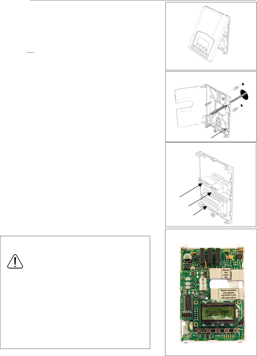
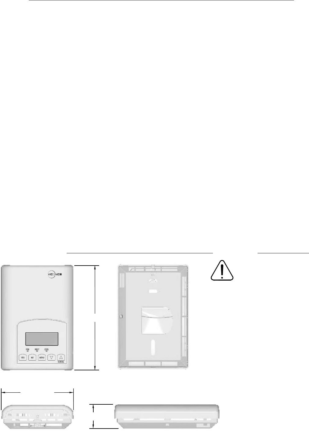
Installation
• Remove security screw on the bottom of thermostat cover.
• Open up by pulling on the bottom side of thermostat.
• Remove Assembly and remove wiring terminals from sticker. (Fig. 3)
• Please note the FCC ID and IC label installed in the cover upon
removal of cover for the wireless products.
A) Location:
1- Should not be installed on an outside wall.
2- Must be installed away from any heat source.
3- Should not be installed near an air discharge grill.
4- Should not be affected by direct sun radiation.
5- Nothing must restrain vertical air circulation to the thermostat.
B) Installation:
1- Swing open the thermostat PCB to the left by pressing the PCB
locking tabs. (Fig. 4)
2- Pull out cables 6” out of the wall.
3- Wall surface must be flat and clean.
4- Insert cable in the central hole of the base.
5- Align the base and mark the location of the two mounting holes
on the wall. Install proper side of base up.
6- Install anchors in the wall.
7- Insert screws in mounting holes on each side of the base.
(Fig. 4)
8- Gently swing back the circuit board on the base and push on it
until the tabs lock it.
10- Strip each wire 1/4 inch.
11- Insert each wire according to wiring diagram.
13- Gently push back into hole excess wring (Fig. 5)
14- Re-Install wiring terminals in correct location. (Fig. 5)
15- Reinstall the cover (top side first) and gently push back extra
wire length into the hole in the wall.
16- Install security screw.
• If replacing an old thermostat, label the wires before
removal of the old thermostat.
• Electronic controls are static sensitive devices.
Discharge yourself properly before manipulation and
installing the thermostat.
• Short circuit or wrong wiring may permanently damage
the thermostat or the equipment.
• Anti-short cycling can be set to 0 minutes for equipment
that posses their own anti cycling timer. Do not use that
value unless the equipment is equipped with such
internal timer. Failure to do so can damage the
equipment.
• All VT7000 series thermostats are to be used only as
operating controls. Whenever a control failure could
lead to personal injury and/or loss of property, it
becomes the responsibility of the user to add safety
devices and/or alarm system to protect against such
catastrophic failures.
Fig.3
Fig.5
Location of PCB retaining tabs
Re-install terminal blocks
Thermostat assembly
(VT7300F5000B shown)
Fig.4
Fig.6
4
Terminal identification
V
iconics Part Numbers
V
T73xxA5x00(x)
V
T73xxC5x00(x)
V
iconics Number
V
T73xxF5x00(x)
Description / Application 2 & 4 Pipe On/Off 2 & 4 Pipe Floating Description / Application 2 & 4 Pipe Analog
2 & 4 Pipe On/Off
Internal Temperature X
X
Internal Temperature
X
Internal Humidity Model Dependent Internal Humidity Model Dependent
1- High Fan Speed Fan-H Fan-H 1- High Fan Speed Fan-H
2- Medium Fan Speed Fan-M Fan-M 2- Medium Fan Speed Fan-M
3- Low Fan Speed Fan-L Fan-L 3- Low Fan Speed Fan-L
4- 24 V~ Hot 24 V~ Hot 24 V~ Hot 4- 24 V~ Hot 24 V~ Hot
5- 24 V~ Com 24 V~ Com 24 V~ Com 5- 24 V~ Com 24 V~ Com
6- Aux BO 5 BO 5-Aux BO 5-Aux 6- Aux BO 5 BO 5-Aux
7- Aux BO 5 BO 5-Aux BO 5-Aux 7- Aux BO 5 BO 5-Aux
8- BO 3 Open Heat BO 3 BO 3
9- BO 4 Close Heat BO 4 9- AO 2 Heat AO 2
10- BO 1 Open Cool BO 1 10- AO 1 Cool AO 1
11- BO 2 Close Cool BO 2 BO 2 Not used Blank Blank
12- BI #1 BI 1 BI 1 12- BI #1 BI 1
13- RS RS RS 13- RS RS
14- Scom Scom Scom 14- Scom Scom
15- BI #2 BI 2 BI 2 15- BI #2 BI 2
16- UI #3 COS / COC /SS UI 3 UI 3 16- UI #3 COS / COC /SS UI 3
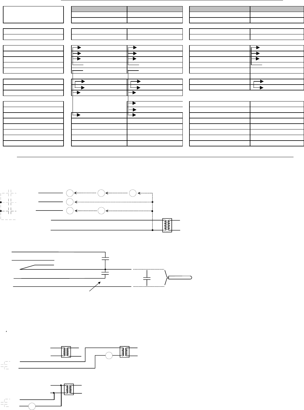
Wiring
Fan-H
Fan-M
Fan-L
24 V~ Hot
24 V~ Com
24 V~ transformer relay pack
3 speed 2 speed Single speed
High
Med
Low
High
Low
High
Power & Fan ( All models )
Remote inputs ( All models )
BI 1
RS
Scom
BI 2
UI 3
OR
Contact
- Rem NSB
- Motion
- Window
Contact
- Door
- Remote Override
- Filter alarm
- service alarm
Remote wall sensor
- S3010W1000
- S3020W1000
SS ( supply sensor )
- S1010E1000
- S2000D1000
COS ( changeover sensor )
- S1010E1000
COC/NH
- Normally heat
- Closed contact = cold water
COC/NC
- Normally cool
- Closed contact = heat water
#4 24 V~ Hot
#5 24 V~ Com
#6
#7
#4 24 V~ Hot
#5 24 V~ Com
#6
#7
Auxiliary output ( All models )
- Dry contact to end device 24 V~ maximum
- 24 Vac power to relay
R
R
5
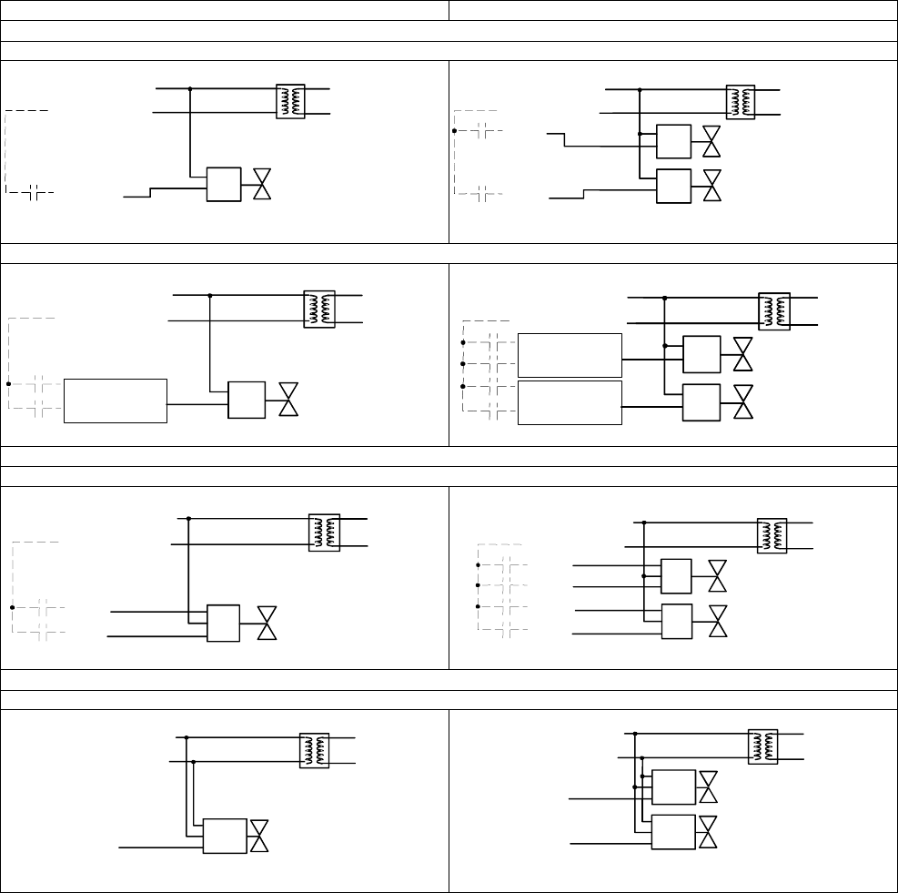
Main outputs wiring
2 Pipe applications 4 Pipe applications
On-Off control
VT7300A5x00(x) & VT7305AC5x00(x)
VT7300C5x00(x), VT7305C5x00(x), VT7350C5x00(x) & VT7355C5x00(x)
Floating control
VT7300C5x00(x), VT7305C5x00(x), VT7350C5x00(x) & VT7355C5x00(x)
Analog control
VT7300F5x00(x), VT7305F5x00(x), VT7350F5x00(x) & VT7355F5x00(x)
N.C. Heating / Cooling valve
24 Vac
Com
24 Vac
Com
24 V~ Hot
24 V~ Com
BO2
24 Vac
Com N.O. Heating valve
N.C. Cooling valve
24 Vac
Com
24 Vac
Com
24 Vac
Com
24 V~ Hot
24 V~ Com
BO3
BO2
Heating / Cooling valve
24 Vac
Com
OR
24 V~ Hot
24 V~ Com
BO1 if N.O.
BO2 if N.C.
24 V~ Hot
24 V~ Com
BO3 if N.O.
BO4 if N.C.
BO1 if N.O.
BO2 if N.C.
24 Vac
Com Heating valve
Cooling valve
24 Vac
Com
OR
OR
24 Vac
Com Heating valve
Cooling valve
24 Vac
Com
OR
OR
Open
Com
Close
Heating / Cooling valve
24 V~ Hot
24 V~ Com
BO1
BO2
Open
Com
Close Heating valve
Open
Com
Close Cooling valve
24 V~ Hot
24 V~ Com
BO3
BO4
BO1
BO2
2
4 V~ Hot
2
4 V~ Com
A
O 2
A
O 1
Com
24 Vac
0-10 Vdc Heating valve
Cooling valve
Com
24 Vac
0-10 Vdc
Heating / Cooling valve
Com
24 Vac
0-10 Vdc
24 V~ Hot
24 V~ Com
A
O 1
6
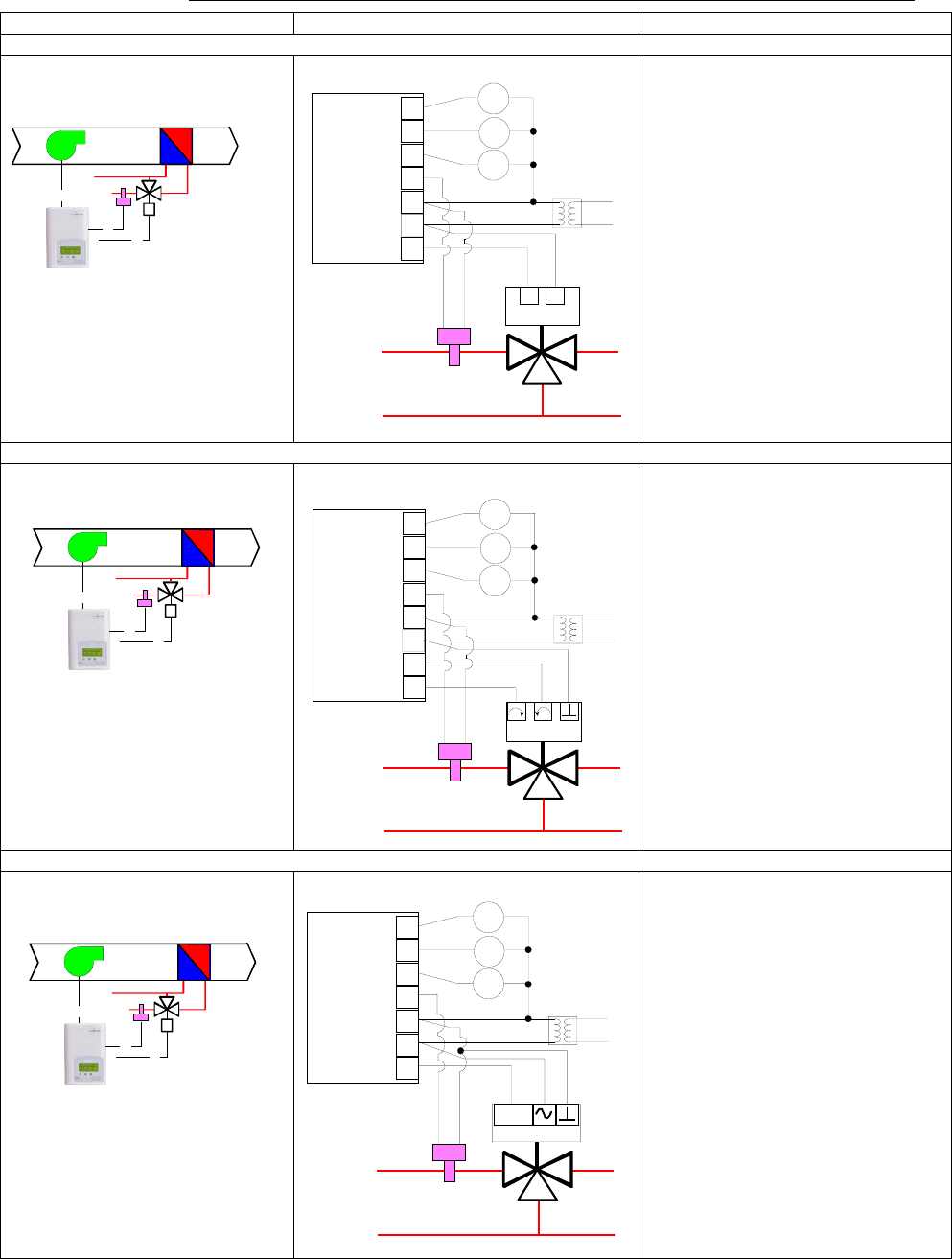
Typical applications
Schematic Wiring Settings
2 pipe system cooling and/or heating: VT7300A5x00(x), VT7300C5x00(x) & VT7305C5x00(x) On / Off N.C. actuator
Mandatory
• Pipe no = 2 pipes
• CntrltTyp = On/Off
• Fan Menu = 0 (L-M-H)
• FL time = as per actuator
If cooling only set::
• SeqOpera = 0 Cooling only
If heating only set::
• SeqOpera = 1 Heating only
If heat / cool auto-changeover with
a local water temperature sensor set:
• SeqOpera = 0 Cooling only
• UI3 = COS
2 pipe system cooling and/or heating: VT7300C5x00(x) & VT7305C5x00(x) Floating actuator
Mandatory
• Pipe no = 2 pipes
• CntrltTyp = Floating
• Fan Menu = 0 (L-M-H)
• FL time = as per actuator
If cooling only set::
• SeqOpera = 0 Cooling only
If heating only set::
• SeqOpera = 1 Heating only
If heat / cool auto-changeover with
a local water temperature sensor set:
• SeqOpera = 0 Cooling only
• UI3 = COS
2 pipe system cooling and/or heating: VT7300F5x00(x) & VT7305F5x00(x) Analog actuator
Mandatory
• Pipe no = 2 pipes
• Fan Menu = 0 (L-M-H)
• RA/DA = as per actuator
If cooling only set::
• SeqOpera = 0 Cooling only
If heating only set::
• SeqOpera = 1 Heating only
If heat / cool auto-changeover with
a local water temperature sensor set:
• SeqOpera = 0 Cooling only
• UI3 = COS
Optional supply water
temperature sensor
UI3 COS
24 V~ Com
24 V~ Hot
BO2 N.C.
Fan-L
Fan-M
Fan-H High
Med
Low
24 Vac fan relays
Normally Closed On/Off
Valve Cooling and/or Heating
Room Temperature
Control Thermostat
3 Speed fan
Optional supply water
temperature sensor
UI3 COS
24 V~ Com
24 V~ Hot
BO1 Open
BO2 Close
Fan-L
Fan-M
Fan-H High
Med
Low
24 Vac fan relays
Modulating Floating
Valve Cooling and/or Heating
Room Temperature
Control Thermostat
3 Speed fan
0 to 10
Vdc
UI3 COS
0 V~ Com
24 V~ Hot
AO1
Optional supply water
temperature sensor
Fan-L
Fan-M
Fan-H High
Med
Low
24 Vac fan relays
Modulating Analog
Valve Cooling and/or Heating
Room Temperature
Control Thermostat
3 Speed fan
7
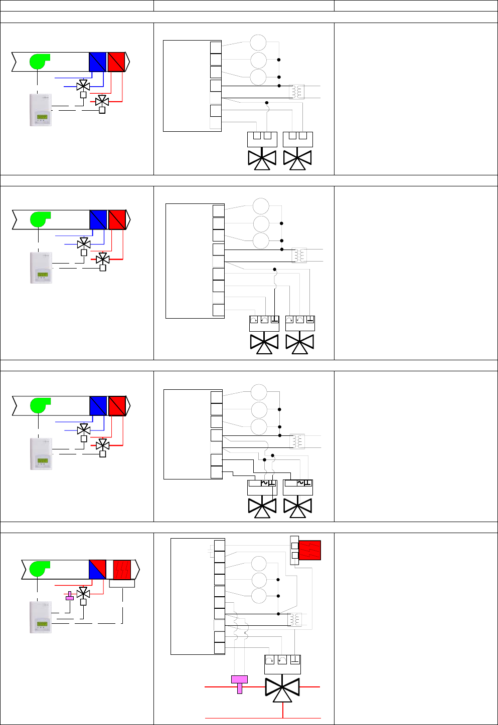
Schematic Wiring Settings
4 pipe system cooling and heating: VT7300C5x00(x) & VT7305C5x00(x) On / Off N.C. actuators
Mandatory
• Pipe no = 4 pipes
• CntrltTyp = On/Off
• Fan Menu = 0 (L-M-H)
• FL time = as per actuator
• SeqOpera = 4 Cool/Heat
4 pipe system cooling and heating: VT7300C5x00(x) & VT7305C5x00(x) Floating actuators
Mandatory
• Pipe no = 4 pipes
• CntrltTyp = Floating
• Fan Menu = 0 (L-M-H)
• FL time = as per actuator
• SeqOpera = 4 Cool/Heat
4 pipe system cooling and heating: VT7300F5x00(x) & VT7305F5x00(x) Analog actuators
Mandatory
• Pipe no = 4 pipes
• Fan Menu = 0 (L-M-H)
• RA/DA = as per actuator
• SeqOpera = 4 Cool/Heat
2 pipe system cooling or heating with reheat: VT7300C5x00(x) & VT7305C5x00(x) Floating actuator
Mandatory
• Pipe no = 2 pipes
• CntrltTyp = Floating
• Fan Menu = 0 (L-M-H)
• FL time = as per actuator
• SeqOpera = 2 Cool/Reheat
• UI3 = COS
24 V~ Com
24 V~ Hot
BO2 Close
Fan-L
Fan-M
Fan-H High
Med
Low
24 Vac fan relays
CoolingHeating
BO4 Close
Normally Closed On/Off
Valve Cooling and Heating
Room Temperature
Control Thermostat
3 Speed fan
24 V~ Com
24 V~ Hot
BO1 Open
BO2 Close
Fan-L
Fan-M
Fan-H High
Med
Low
24 Vac fan relays
Cooling
Heating
BO3 Open
BO4 Close
Modulating Floating
Valve Cooling and Heating
Room Temperature
Control Thermostat
3 Speed fan
24 V~ Com
24 V~ Hot
AO1
AO2
Fan-L
Fan-M
Fan-H High
Med
Low
24 Vac fan relays
Cooling
Heating
0 to 10
Vdc 0 to 10
Vdc
Modulating Analog
Valve Cooling and Heating
Room Temperature
Control Thermostat
3 Speed fan
Optional supply water
temperature sensor
UI3 COS
24 V~ Com
24 V~ Hot
BO1 Open
BO2 Close
Fan-L
Fan-M
Fan-H High
Med
Low
24 Vac fan relays
BO5
BO5
Modulating Floating
Valve Cooling and/or Heating
Room Temperature
Control Thermostat
3 Speed fan
Electric
Reheat
8
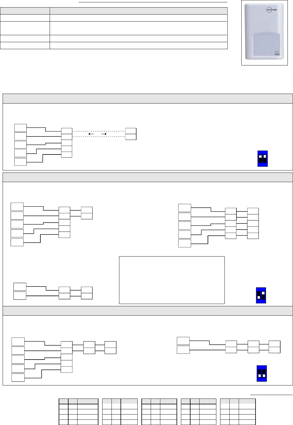
Remote sensor accessories
Model no. Description
S3010W1000 Wall mounted temperature sensor
S3020W1000 Wall mounted temperature sensor with override button and
occupancy status LED
S2060A1000 Averaging temperature sensor
S2000D1000 Duct mounted temperature sensor
Remote mount temperature sensors use 10K type 2 NTC thermistors.
Features:
• Each sensor can be configured for various averaging combinations FIG.8 – S3020W1000 WALL
MOUNTED SENSOR
• Optional occupancy led
• Optional override key
Wiring example of single remote room sensor:
Wiring examples of 2 remote room sensors for averaging applications:
S3020W1000
Remote wiring 1 sensor
S2=On, S3=On
VT7300 Series
Thermostat
BO 5
BI 2
RS
Scom Scom
RS
Scom
RS
C
DI
Aux
Scom
RS
Scom
RS
OR
S3010W1000
Remote wiring 1 sensor
S2=On, S3=On
24 Vac
Com
12
ON
Dip switch
setting for:
1 senso
r
S2-1 = ON
S2-2 = ON
VT7300 Series
Thermostat 1 x S3010W1000 and 1 x S3020W1000
Remote wiring 2 sensors
S1=On, S2=Off
Scom
RS
Scom
RS
2 x S3020W1000
Remote wiring 2 sensors
S2=On, S3=Off
Scom
RS
Scom
RS
C
DI
Aux
VT7300 Series
Thermostat
BO 5
BI 2
RS
Scom
24 Vac
Com
Scom
RS
Scom
RS
C
DI
Aux
Scom Scom
RS
Scom
RS
RS
Wiring examples of 3 remote room sensors for averaging applications:
Temperature vs resistance chart for 10 Kohm NTC thermistor (R25°C = 10KΩ±3%, B25/85°C = 3975K±1.5%)
ºC ºF Kohm ºC ºF Kohm ºC ºF Kohm ºC ºF Kohm ºC ºF Kohm
-40 -40 324.3197 -20 -4 94.5149 0 32 32.1910 20 68 12.4601 40 104 5.3467
-35 -31 234.4009 -15 5 71.2430 5 41 25.1119 25 77 10.0000 45 113 4.3881
-30 -22 171.3474 -10 14 54.1988 10 50 19.7390 30 86 8.0694 50 122 3.6202
-25 -13 126.6109 -5 23 41.5956 15 59 15.6286 35 95 6.5499 55 131 3.0016
Notes for averaging applications:
• S3010W1000 and S3020W1000 can be
mixed matched.
• S3010W1000 and S3020W1000 are to
be wired in parallel.
• Respect the dip switch setting in each
remote sensor. 12
ON
Dip switch
setting for:
2 sensors
S2-1 = OFF
S2-2 = ON
12
ON
Dip switch
setting for:
3 sensors
S2-1 = OFF
S
2
-
2
=
OFF
2x S3010W1000 and 1 x S3020W1000
Remote wiring 3 sensors
S2=Off, S3=Off
Scom
RS
Scom
RS
Scom
RS
Scom
RS
VT7300 Series
Thermostat
BO 5
BI 2
RS
Scom
24 Vac
Com
Scom
RS
Scom
RS
C
DI
Aux
3x S3010W1000
Remote wiring 3 sensors
S2=Off, S3=Off
Scom
RS
Scom
RS
Scom
RS
Scom
RS
VT7300 Series
Thermostat
RS
Scom Scom
RS
Scom
RS
BO 5
BI 2
24 Vac
Com
Aux
C
DI
2 x S3010W1000
Remote wiring 2 sensors
S2=On, S3=Off
Scom
RS
Scom
RS
VT7300 Series
Thermostat
RS
Scom Scom
RS
Scom
RS
9
Programming and status display instructions
Status display
The thermostat features a two-line, eight-character display. There is a low level backlight level that is always active and
can only be seen at night.
When left unattended, the thermostat has an auto scrolling display that shows the actual status of the system. There is
an option in the configuration menu to lockout the scrolling display and to only present the room temperature and
conditional outdoor temperature to the user. With this option enabled, no local status is given of mode, occupancy and
relative humidity.
Each item is scrolled one by one with the back lighting in low level mode. Pressing any key will cause the back light to
come on to high level. When left unattended for 10 seconds after changes are made, the display will resume automatic
status display scrolling.
To turn on the back light to high level, press any key on the front panel. The back lit display will return to low level when
the thermostat is left unattended for 45 seconds
Sequence of auto-scroll status display:
Room & Humidity System Mode Schedule Status Outdoor Temperature Alarms
x.x °C or °F Sys mode Occupied Outdoor Service
XX % RH Auto x.x °C or°F
If humidity display
enabled Sys mode
Cool Stand-By
Network value only Filter
RoomTemp
x.x °C or °F Sys mode
heat Unoccup
Window
If humidity display is not
enabled Sys mode
off Override
% RH display is conditional to:
(Humidity display is model and configuration dependent)
• Model with RH sensor built in
• Display function can be enabled with RH display parameter. Displayed range is 10 to 90 % RH
Outdoor air temperature
• Display is only enabled when outdoor air temperature network variable is received.
Occupancy Status
• Occupied, Stand-By, Unoccupied and Override status are displayed on the scrolling display.
Alarms
• If alarms are detected, they will automatically be displayed at the end of the status display scroll.
• During an alarm message display, the backlit screen will light up at the same time as the message and shut off
during the rest of the status display.
• Two alarms maximum can appear at any given time. The priority for the alarms is as follows:
Service Indicates that there is a service alarm as per one of the programmable binary input ( BI2 )
Filter Indicates that the filters are dirty as per one of the programmable binary input ( BI2 )
Window Indicates that the outside window or door is opened and that the thermostat has cancelled any cooling or
heating action ( BI1 )
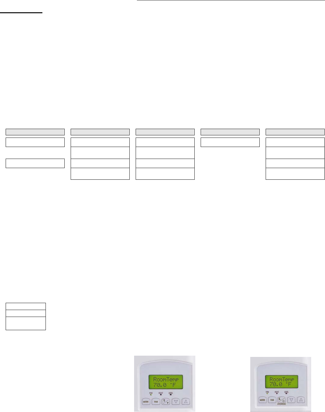
Three status LED’s on the thermostat cover are used to indicate the status of the fan ( any speed ), a call for heat, or a call for
cooling.
Fan coil models
• When any of the fan speeds are ON,
the FAN LED will illuminate.
• When heating & reheat is ON,
the HEAT LED will illuminate.
• When cooling is ON,
the COOL LED will illuminate. Fig.11 – Hotel models °C/°F Fig. 12 Commercial models with Override
10
Installer configuration parameter menu
Configuration can be done through the network or locally at the thermostat.
• To enter configuration, press and hold the middle button (°C/°F or Override) for 8 seconds
• Press the same middle button repetitively to scroll between all the available parameters
• Use the up and down key to change the parameter to the desired value.
• To acknowledge and save the new value, press the middle button again.
• The next listed parameter is now displayed
Configuration interface
Fan Re-starts the configuration parameter list at the beginning
°C/°F
Override Enters the configuration mode. Press and hold for 8 seconds
Pressing repetitively will scroll all available parameters one by one
Down Adjust / rotate parameter value down
Up Adjust / rotate parameter value up
User interface
• Unoccupied mode Override
An Override can be made on commercial models during an Unoccupied period. If the Override option is enabled in the
lockout configuration pressing the middle override button will resume occupied setpoints for a time specified by
parameter ToccTime
• Keypad interface
System Is used to toggle between the different system mode available as per sequence and menu selected
Pressing repetitively the button will toggle between all the available modes
Available menus are dependent on selected sequence of operation
Fan Is used to toggle between the different fan mode available as per sequence and menu selected
Pressing repetitively the button will toggle between all the available modes
Available menus are dependent on selected sequence of operation and menu selected for Fan
°C/°F
Override
Middle key is
• °C / °F for Hotel models
• Override for commercial models
Down
Adjust the setpoints down
In cooling mode only the cooling setpoint displayed,
In heating mode only the heating setpoint displayed
In auto mode, (See below)
Up
Adjust the setpoints up
In cooling mode only the cooling setpoint displayed,
In heating mode only the heating setpoint displayed
In auto mode, (See below)
1. Any setpoint change can be permanent or temporary based on configuration parameter (Setpoint Type)
2. Any setpoint written through the network, will be permanent and cancel any active temporary setpoints
3. Lockouts of access to certain functions is made with configuration parameter (lockout)
• Occupied setpoint adjustments
Cooling
mode Heating
mode Off mode
Auto Mode
• Setpoint presented to user is the setpoint from the last
action taken by the thermostat or the one currently in use.
• If the other setpoint is the one desired, then the MODE
button is used to toggle between the current displayed one
and the other.
Cool XX.X °F or
°C Heat XX.X °F or
°C No access to
setpoint Cool XX.X °F or °C or Heat XX.X °F or °C
Toggle to ( Heat or Cool )with MODE button
• Heat/Cool setpoint toggle with MODE button to be active only in AUTO mode.
• If cooling, heating or off mode is active, function is disabled
• Unoccupied and Stand-By setpoints adjustments
Setting the stand-by and unoccupied setpoints is done through the network or through configuration setup only.
11
• Mode button menu sequence.
- Modes presented to the user are dependent on sequence of operation selected
- Default mode is in bold when sequence of operation parameter is changed
- * Auto mode menu can be disabled with (AutoMode) parameter
Sequence selected Mode Menu
0 = Cooling only Off - Cool
1 = Heating only Off - Heat
2 = Cooling With Reheat Off – Auto *– Heat – Cool
3 = Heating With Reheat Off - Heat
4 = Cooling / Heating 4 pipes Off – Auto *– Heat – Cool
5 = Cooling / Heating 4 pipes with Reheat Off – Auto *– Heat – Cool
* Auto. The Auto mode can be disabled from the menu with the (AutoMode) parameter
• Available fan button menu sequences.
Fan button menu
configuration Menu presented are dependent on model used
and sequence of operation selected Default value when
sequence toggled
0 Low-Med-High 3 Speed configuration using 3 fan relays ( L-M-H ) High
1 Low-High 2 Speed configuration using 2 fan relays ( L-H ) High
2 Low-Med-High-Auto 3 Speed configuration with Auto fan speed mode using 3 fan relays ( L-M-H ) High
3 Low-High-Auto 2 Speed configuration with Auto fan speed mode using 2 fan relays ( L-H ) High
4 On-Auto Single Speed configuration. Auto is for Fan on demand / On is On all the time Auto
Auto speed fan mode is also offered in heating mode applications; it will not however have any effect on dehumidification. It will be
strictly for noise comfort issues
Configuration parameters
Default value Significance and adjustments
Com Addr
Thermostat networking address
Default value = 4
Range is: 0 to 254
Conditional parameter to BACnet MS-TP models (VT730xX1000B)
Conditional parameter to Wireless models (VT730xX1000W)
This parameter will only appear when a BACnet or wireless network adapter is
present. If the thermostat is installed as a stand-alone unit or with an Echelon
adapter, this parameter will not be used or displayed
• For BACnet MS-TP models valid range to use is from 1 to 127
• For wireless models valid range is 0 to 254 with a maximum of 30 thermostat per
VGG
PAN ID
Personal Area Network
Identification
Default value = 0
Range is: 0 to 500
Conditional parameter to Wireless models (VT730xX1000W)
This parameter will only appear when a wireless network adapter is present. If the
thermostat is installed as a stand-alone unit or with a BACnet or Echelon adapter,
this parameter will not be used or displayed
This parameter (Personal Area Network Identification) is used to link specific
thermostats to a single specific Viconics wireless gateway ( VWG ) For every
thermostat reporting to a gateway ( maximum of 30 thermostats per gateway ), be
sure you set the SAME PAN ID value both at the gateway and the thermostat(s).
The default value of 0 is NOT a valid PAN ID. The valid range of available PAN ID
is from 1 to 500
Channel
Channel selection
Default value = 10
Range is: 10 to 26
Conditional parameter to Wireless models (VT73x0X1000W)
This parameter will only appear when a wireless network adapter is present. If the
thermostat is installed as a stand-alone unit or with a BACnet or Echelon adapter,
this parameter will not be used or displayed
This parameter (Channel) is used to link specific thermostats to specific Viconics
wireless gateway(s) ( VWG ) For every thermostat reporting to a gateway (
maximum of 30 thermostats per gateway ), be sure you set the SAME channel
value both at the gateway and the thermostat(s).
Viconics recommends using only the 2 last channels ( 25-2575MHz and 26-
2580MHz )
The default value of 10 is NOT a valid channel. The valid range of available
channel is from 11 to 26

12
Get From
Thermostat Get From another
device configuration utility
Default value = 0
Range is: 0 to 254
Conditional parameter to Wireless models (VT730xX1000W)
This parameter / function is not currently supported by the wireless
thermostats.
BI1
Binary input no.1 configuration
Default value = None
(None): No function will be associated with the input
(Rem NSB): remote NSB timer clock input. The scheduling will now be set as per
the binary input. It provides low cost setback operation via a dry contact
Contact opened = Occupied
Contact closed = Unoccupied
(Motion NO) or (Motion NC): Advanced PIR occupancy functions using a
Normally Open (NO) or Normally Closed (NC) remote PIR motion sensor.
Occupancy mode is now set as per applied PIR function and configuration.
Application information and examples are available on document: APP-PIR-
Guide-Exx. This document will provide the installers and system designers with
detailed examples on applications, parameter configuration information,
sequence of operation, troubleshooting and diagnostic help required for the
proper usage of the PIR accessory covers
(Window) EMS: Forces the system to disable any current heating or cooling
action by the thermostat. The mode stays the same and the current setpoints are
the same Occupied setpoints. Only the outputs are disabled. There is a
Door/Window alarm displayed on the thermostat to indicate to the local tenant
that the door/window needs to be closed for cooling or heating to resume.
* these settings will disable the local override function on the thermostat.
BI2
Binary input no.2 configuration
Default value = None
(None): No function will be associated with the input
(Door Dry) Door contact & Motion detector: This configuration is only
functional if binary input #1 is set to Motion NO or Motion NC or a PIR
accessory cover is used.
With this sequence enabled, the occupancy is now dictated through those 2
inputs. Any motion detected will set the zone to occupied status. The zone will
remain permanently in occupied mode until the door contact switch opens
momentarily. The thermostat will then go in stand-by mode. If more movements
are detected, the occupied mode will resume. While the door is opened, any
movements detected by the remote PIR sensor or the PIR accessory cover will
be ignored. Use a Normally Closed contact switching device.
Contact opened = Door opened
Contact closed = Door closed
(RemOVR): temporary occupancy remote override contact. This function disables
the central button override function on the thermostat. The override function is
now controlled by a manual remote momentarily closed contact. When configured
in this mode, the input operates in a toggle mode.
It is now possible to toggle between unoccupied & occupied setpoints for the
amount of time set by parameter (TOccTime) temporary occupancy time.
(Filter): a backlit flashing Filter alarm will be displayed on the thermostat LCD
screen when the input is energized. It can be tied to a differential pressure switch
that monitor filters
Contact opened = No alarm
Contact closed = Alarm displayed
(Service): a backlit flashing Service alarm will be displayed on the thermostat
LCD screen when the input is energized. It can be tied in to the AC unit control
card, which provides an alarm in case of malfunction.
Contact opened = No alarm
Contact closed = Alarm displayed

13
UI3
Universal input no.3 configuration
Default value = None
(None): No function will be associated with the input
(COC/NH) Change over dry contact. Normally Heat: Used for hot / cold water or
air change over switching in 2 pipe systems.
Contact closed = Cold water or air present
Contact opened = Hot water or air present
Only used and valid if system is setup as 2 pipes. Parameter ( Pipe No ) set as 2
pipes.
(COC/NC) Change over dry contact. Normally Cool: Used for hot / cold water or
air change over switching in 2 pipe systems.
Contact closed = Hot water present
Contact opened = Cold water present
Only used and valid if system is setup as 2 pipes. Parameter (Pipe No ) set as 2
pipes.
(COS) Change over analog sensor: Used for hot / cold water or air change over
switching in 2 pipe systems.
Only used and valid if system is setup as 2 pipes. Parameter (Pipe No ) set as 2
pipes.
If water temperature is > 78 °F = Hot water present
If water temperature is < 75 °F = Cold water present
(SS) Supply air sensor monitoring: Used for supply air temperature monitoring.
Only used for network reporting of the supply air temperature. Has no internal
function in the thermostat.
MenuScro
Menu scroll
Default value = On = Scroll active
Removes the scrolling display and only present the room temperature/humidity to the user.
With this option enabled, no status is given of mode, schedule and outdoor temperature.
On = Scroll active
Off = Scroll not active
AutoMode
Enables Auto menu for Mode
button
Default value = Off
Enables Auto function for the mode button
For sequences 2, 4 & 5 only
On = Auto active (Off-Cool-Heat-Auto)
Off = auto not active (Off-Cool-Heat)
C or F
Sets scale of the thermostat
Default value = °F
°F for Fahrenheit scale
°C for Celsius scale
On hotel models, this sets the default value when the thermostat powers up
%RH disp
Local %RH Display
Default value = OFF
Models with Humidity sensor only
VT735xX5x00(x) models only
RH models only
Enables the display of humidity below the room temperature on the display
ON = Display %RH
OFF = No display of %RH
Lockout
Keypad lockout levels
Default value = 0 No lock
Level Occupied temperature
setpoints System mode setting Fan mode setting Unoccupied Override
0 Yes access Yes access Yes access Yes access
1 Yes access Yes access Yes access No access
2 Yes access No access No access Yes access
3 Yes access No access No access No access
4 No access No access No access Yes access
5 No access No access No access No access
Pipe No
System type installation
Number of pipes
Default is: 4.0 Pipes
Defines the type of system installed
2.0 Pipes, will limit the number of sequences of operation available from 0 to 3
Will enable heat/cool operation from the same output ( refer to wiring diagram )
4.0 Pipes, can access all the sequences of operation from 0 to 5
Will enable heat/cool operation from different output ( refer to wiring diagram )

14
CntrlTyp
Control type for Triac models
Default is: Floating
Defines the type of control output for the type of valves installed
VT7350C10xx, VT7300C10xx, VT7355C10xx and VT7305C10xx only
On/Off is for normally opened or normally closed 24 Vac 2 position valves
Floating is for modulating 3 wires control of 24 Vac floating valves
SeqOpera Sequence of operation
Default is: Sequence #1 System = 2 Pipes System = 4 Pipes
0 = Cooling Only Yes access Yes access
1 = Heating only Yes access Yes access
2 = Cooling With Reheat Yes access Yes access
3 = Heating With Reheat Yes access Yes access
4 = Cooling / Heating 4 pipes No access Yes access
5 = Cooling / Heating 4 pipes with
Reheat No access Yes access
For single output applications, the system access is also limited if UI3 is configured
for local changeover COS, COC/NC or COC/NC. The system mode available for
the local configuration or network write is then limited by the current water
temperature detected by the UI3.
Fan Menu
Mode button menu configuration
Default is: Menu #4
Menu presented are dependent on model used and sequence of operation
selected
0 = Low-Med-High 3 Speed configuration using 3 fan relays ( L-M-H )
1 = Low-High 2 Speed configuration using 2 fan relays ( L-H )
2 = Low-Med-High-Auto 3 Speed configuration with Auto fan speed mode using 3 fan relays ( L-M-H )
3 = Low-High-Auto 2 Speed configuration with Auto fan speed mode using 2 fan relays ( L-H )
4 = On-Auto Single Speed configuration. Auto is for Fan on demand / On is On all the time
DHumiLCK
Dehumidification lockout
VT735xX5x00(x) models only
Default value: On = Authorized
Typically toggled through the network.
This variable enables or disables dehumidification based on central network
requirements from the BAS front end
On = Dehumidification Authorized
Off = Dehumidification Not Authorized
%RH set
Dehumidification setpoint
Default is 50 % RH
Used only if dehumidification sequence is enabled:
Range is: 30-95% RH
VT735xX5x00(x) models only
DehuHyst
Dehumidification Hysterisys
Default is 5 % RH
Humidity control hysterisys. Used only if dehumidification sequence is enabled:
Range is: 2 to 20% RH
VT735xX5x00(x) models only
DehuCool
Maximum Dehumidification
Cooling output
Default is 100 %
Maximum cooling valve position when dehumidification is enabled. This can be
used to balance smaller reheat loads installed in regards to the capacity of the
cooling coil.
Range is: 20 to 100 %
VT735xX5x00(x) models only
St-By TM
Stand-by Timer value
Default 0.5 hours
Time delay between the moment where the PIR cover detected the last movement
in the area and the time which the thermostat stand-by mode and setpoints
become active.
Range is: 0.5 to 24.0 hours in 0.5hr increments
Unocc TM
Unoccupied Timer value
Default 0.0 hours
Time delay between the moment where the thermostat toggles to stand-by mode
and the time which the thermostat unoccupied mode and setpoints become active.
The factory value or 0.0 hours: Setting this parameter to its default value of 0.0
hours disables the unoccupied timer. This prevents the thermostat to drift from
stand-by mode to unoccupied mode when PIR functions are used
Range is: 0.0 to 24.0 hours in 0.5hr increments
St-By HT
Stand-by heating setpoint
Default value = 69 °F
The value of this parameter should reside between the occupied and unoccupied
heating setpoints and make sure that the difference between the stand-by and
occupied value can be recovered in a timely fashion when movement is detected
in the zone.
Stand-by heating setpoint range is: 40 to 90 °F ( 4.5 to 32.0 °C )

15
St-By CL
Stand-by cooling setpoint limit
Default value = 78 °F
The value of this parameter should reside between the occupied and unoccupied
cooling setpoints and make sure that the difference between the stand-by and
occupied value can be recovered in a timely fashion when movement is detected
in the zone.
Stand-by cooling setpoint range is: 54 to 100 °F ( 12.0 to 37.5 °C )
Unocc HT
Unoccupied heating setpoint
Default value = 62 °F
Unoccupied heating setpoint range is:
40 to 90 °F ( 4.5 to 32.0 °C )
Unocc CL
Unoccupied cooling setpoint limit
Default value = 80 °F
Unoccupied cooling setpoint range is:
54 to 100 °F ( 12.0 to 37.5 °C )
heat max
Maximum heating setpoint limit
Default value = 90 °F ( 32 °C )
Maximum occupied & unoccupied heating setpoint adjustment.
Heating setpoint range is:
40 to 90 °F ( 4.5 to 32.0 °C )
cool min
Minimum cooling setpoint limit
Default value = 54 °F ( 12 °C )
Minimum occupied & unoccupied cooling setpoint adjustment.
Cooling setpoint range is:
54 to 100 °F ( 12.0 to 37.5 °C )
Set Type
Temporary setpoint enable
Default is : Permnent
Enables temporary setpoints
feature to any change of
occupied or unoccupied setpoint.
Temporar: (temporary) Local changes to the heating or cooling setpoints by the
user are temporary. They will remain effective for the duration specified by
ToccTime. Setpoints will revert back to their default value after internal timer
ToccTime expires.
To change setpoints permanently, revert to No this variable or write setpoints
through the network. Any setpoints written through the network will be permanent
ones and saved to EEPROM.
Permnent: (permanent) Any change of occupied or unoccupied setpoints through
the keypad by the user are permanent and saved to & EEPROM
TOccTime
Temporary occupancy time
Default value = 2 hours
Temporary occupancy time with occupied mode setpoints when override function
is enabled
When the thermostat is in unoccupied mode, function is enabled with either the
menu or UI2 configured as remote override input.
Range is: 0,1, 2, 3, 4, 5, 6, 7, 8, 9, 10, & up to 24 hours
deadband
Minimum deadband
Default value = 2.0 °F ( 1.0 °C )
Minimum deadband value between the heating and cooling setpoints. If modified,
it will be applied only when any of the setpoints are modified.
Range is: 2, 3, 4 or 5 °F, 1.0 °F increments ( 1.0 to 2.5 °C, 0.5 °C increments )
cal RS
Room temperature sensor
calibration
Default value = 0.0 °F or °C
Offset that can be added/subtracted to actual displayed room temperature
Range is: ± 5.0 °F, 1.0 °F increments ( ± 2.5 °C, 0.5 °C increments )
cal RH
Humidity sensor calibration
Default value = 0 %RH
Offset that can be added/subtracted to actual displayed humidity by ± 15.0 %RH.
Range is : ± 15.0 %RH

16
aux cont
Auxiliary contact function &
configuration
Default value = 0 Not Used
0 Aux contact function used for reheat
IF SEQUENCE IS SET TO REHEAT THROUGH NETWORK OR LOCAL, Ignore
this parameter
The output will directly follow the occupancy of the thermostat
1 Auxiliary NO, Occ or St-By = Contact Closed / Unoccupied = Contact Opened
2 Auxiliary NC, Occ or St-By = Contact Opened / Unoccupied = Contact Closed
Output to follow directly main occupancy and Fan on command
Typically used for 2 position fresh air damper applications.
3 Auxiliary NO, Occ or St-By & Fan On = Contact Closed / Unoccupied & Fan On
or Off = Contact Opened
4 Auxiliary NC, Occ or St-By & Fan On = Contact Opened / Unoccupied & Fan
On or Off = Contact Closed
Output to follow secondary network occupancy command
5 Auxiliary On/Off Control through auxiliary network command. The output can
be commanded through the network for any required auxiliary functions through a
separate & dedicated network variable.
FL time
For floating models
VT73xxC5x00(x) only
Default value: 1.5 minutes
Floating actuator timing
Maximum stroke time of floating valve actuator.
Range is: 0.5 to 9.0 minutes in 0.5 minutes increment
cph
On/Off devices cycles per hour
For On/Off models & sequences
VT73xxC5x00(x) only
Default value = 4 C.P.H.
Will set the maximum number cycles per hour under normal control operation. It
represents the maximum number of cycles that the equipment will turn ON and
OFF in one hour.
Note that a higher C.P.H will represent a higher accuracy of control at the expense
of wearing mechanical components faster.
Range is: 3, 4, 5, 6,7 & 8 C.P.H.
RA/DA
For Analog models
VT73xxF5x00(x) only
Default value: DA signal
Reverse acting or Direct acting signal for Analog output signals
DA = Direct acting, 0 to 100 % = 0 to 10 Vdc
RA = Reverse acting, 0 to 100 % = 10 to 0 Vdc
Reheat
Default value: 0 = 15 minute
Sets the reheat output time base
Valid only if reheat sequences are enabled
0 = 15 minutes
1 = 10 seconds for Solid state relays
UI3 dis
Display UI3 value.
Used as diagnostic / service help to troubleshoot and diagnose sensor operation
Supply or change over temperature when UI3 is configured as an analog input
( SS or COS )
17
Specifications
Thermostat power requirements: 19-30 Vac 50 or 60 Hz; 2 VA Class 2
Operating conditions: 0 °C to 50 °C ( 32 °F to 122 °F )
0% to 95% R.H. non-condensing
Storage conditions: -30 °C to 50 °C ( -22 °F to 122 °F )
0% to 95% R.H. non-condensing
Temperature sensor: Local 10 K NTC thermistor
Temperate sensor resolution: ± 0.1 °C ( ± 0.2 °F )
Temperature control accuracy: ± 0.5 ° C ( ± 0.9 °F ) @ 21 °C ( 70 °F ) typical calibrated
Humidity sensor and calibration: Single point calibrated bulk polymer type sensor
Humidity sensor precision: Reading range from 10-90 % R.H. non-condensing
10 to 20% precision is 10%
20% to 80% precision is 5%
80% to 90% precision is 10%
Humidity sensor stability Less than 1.0 % yearly (typical drift)
Dehumidification setpoint range: 30% to 95% R.H.
Occ, Stand-By and Unocc cooling setpoint range: 12.0 to 37.5 °C ( 54 to 100 °F )
Occ, Stand-By and Unocc heating setpoint range: 4.5 °C to 32 °C ( 40 °F to 90 °F )
Room and outdoor air temperature display range -40 °C to 50 °C ( -40 °F to 122 °F )
Proportional band for room temperature control: Cooling & Heating: 1.8°C ( 3.2°F )
Binary inputs: Dry contact across terminal BI1, BI2 & UI3 to Scom
Contact output rating: Fan relay output: 30 Vac, 1 Amp. Maximum, 3 Amp. in-rush
Valve triac output: 30 Vac, 1 Amp. Maximum, 3 Amp. in-rush
Valve analog: 0 to 10 Vdc into 2KΩ resistance min.
Wire gauge 18 gauge maximum, 22 gauge recommended
Dimensions: 4.94” x 3.38” x 1.13”
Approximate shipping weight: 0.75 lb ( 0.34 kg )
Agency Approvals all models: UL: UL 873 (US) and CSA C22.2 No. 24 (Canada), File E27734
with CCN XAPX (US) and XAPX7 (Canada)
Industry Canada: ICES-003 (Canada)
Agency Approvals Stand-Alone, BACnet & LON models FCC: Compliant to CFR 47, Part 15, Subpart B, Class A (US)
CE: EMC Directive 89/336/EEC (Europe Union)
C-Tick: AS/NZS CISPR 22 Compliant (Australia / New Zealand)
Supplier Code Number N10696
Agency Approvals Wireless models FCC: Compliant to: Part 15, Subpart C
THIS DEVICE COMPLIES WITH PART 15 OF THE FCC RULES. OPERATION IS SUBJECT TO THE FOLLOWING TWO
CONDITIONS: (1) THIS DEVICE MAY NOT CAUSE HARMFUL INTERFERENCE, AND (2) THIS DEVICE MUST ACCEPT
ANY INTERFERENCE RECEIVED, INCLUDING INTERFERENCE THAT MAY CAUSE UNDESIRED OPERATION.
Drawing & Dimensions
3.38" [86 mm]
1.13" [29 mm]
4.94" [125 mm]
Fig.13 – Thermostat dimensions
Important Notice
All VT7300 series
controls are for use as
operating controls only
and are not safety
devices. These instruments have
undergone rigorous tests and
verifications prior to shipment to
ensure proper and reliable operation in
the field. Whenever a control failure
could lead to personal injury and/or
loss of property, it becomes the
responsibility of the user / installer /
electrical system designer to
incorporate safety devices ( such as
relays, flow switch, thermal
protections, etc…) and/or alarm
system to protect the entire system
against such catastrophic failures.
Tampering of the devices or miss
application of the device will void
warranty.