Viessmann Elektronik VC0218 Vitoconnect User Manual
Viessmann Elektronik GmbH Vitoconnect Users Manual
UserManual.wiki
>
Viessmann Elektronik
>
VC0218 User Manual
>
Users Manual
Contents
1.
Users Manual - safety
2.
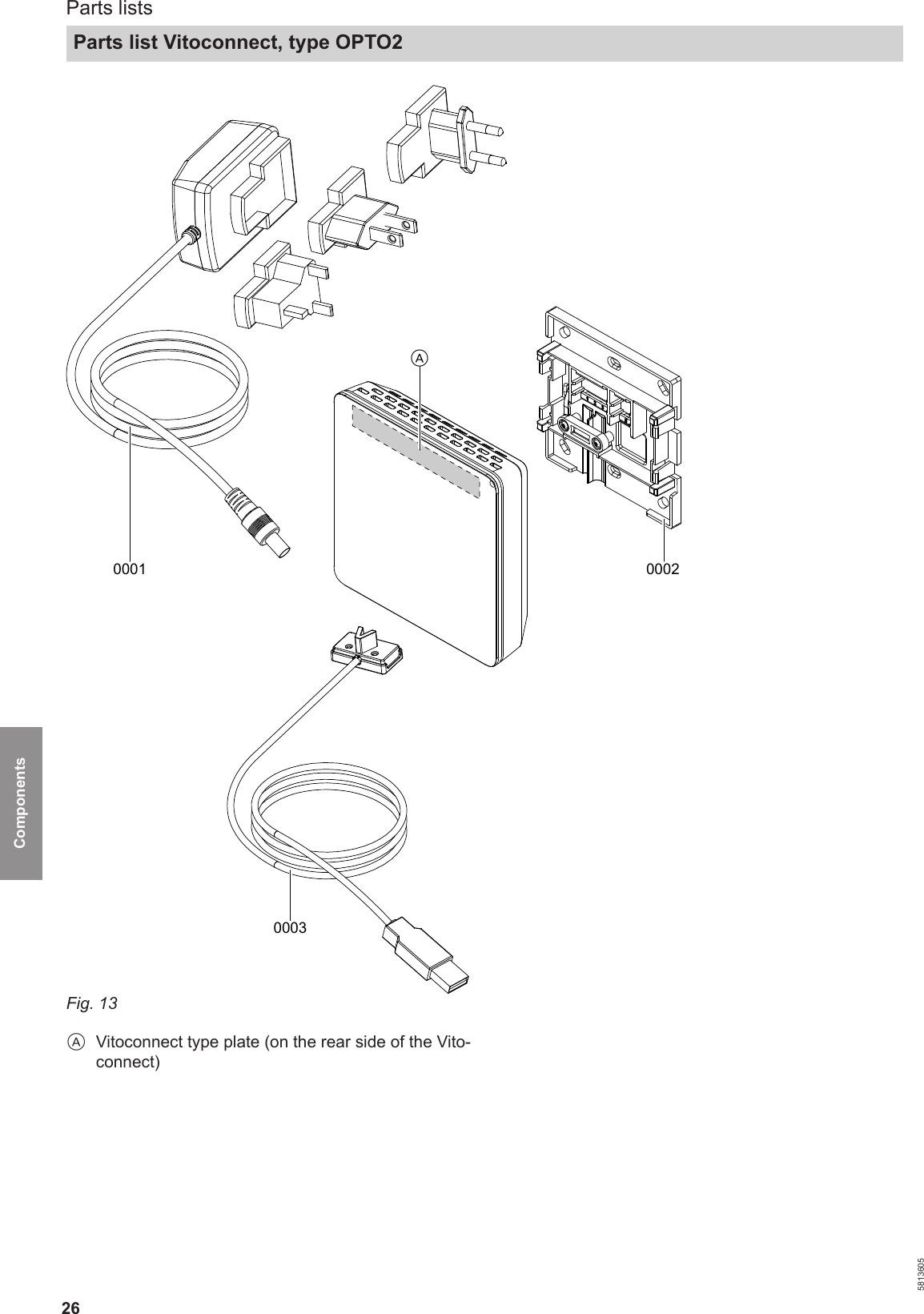
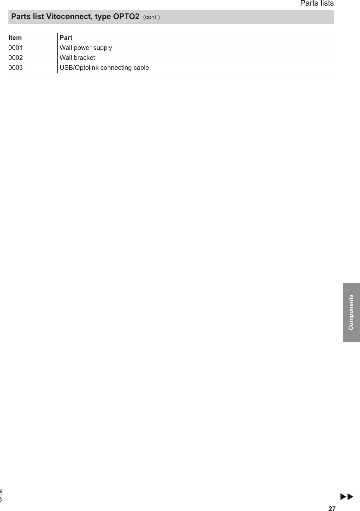
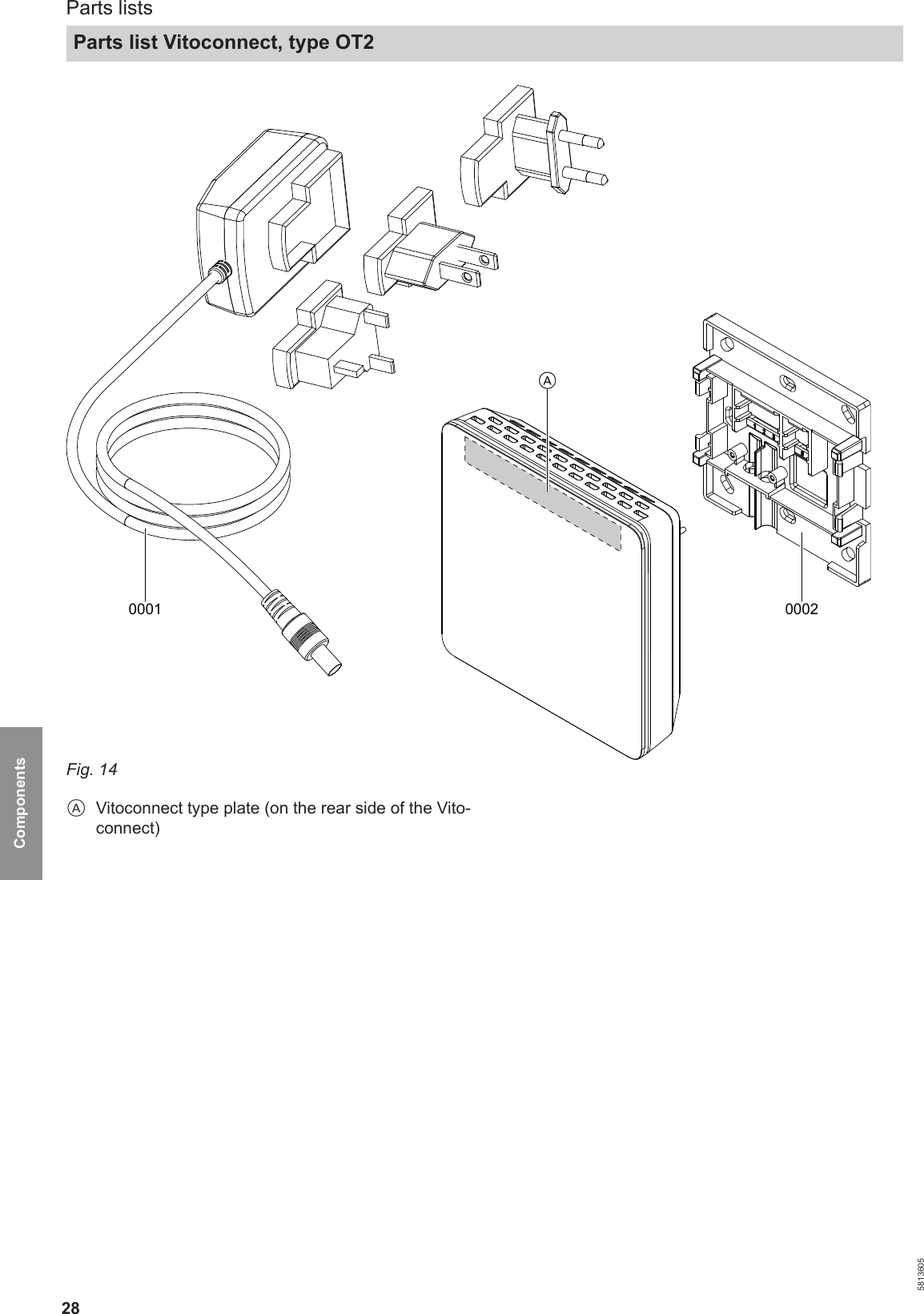
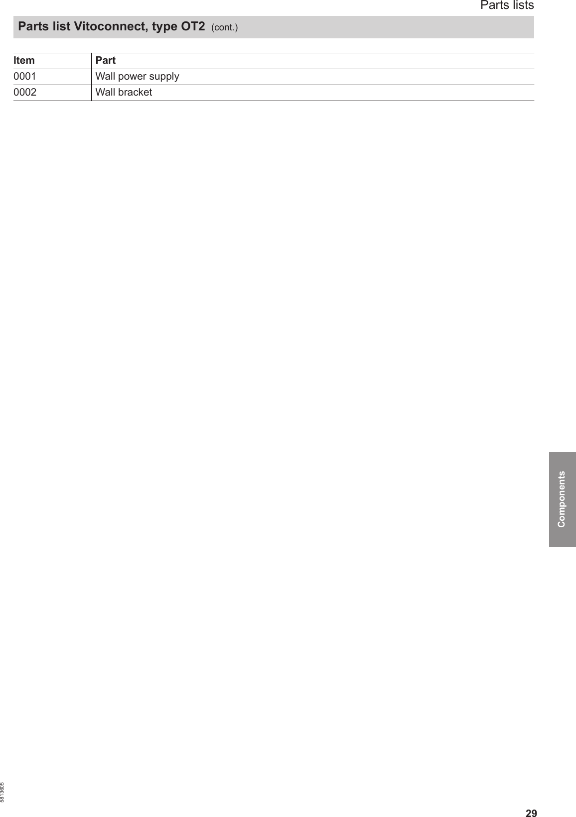
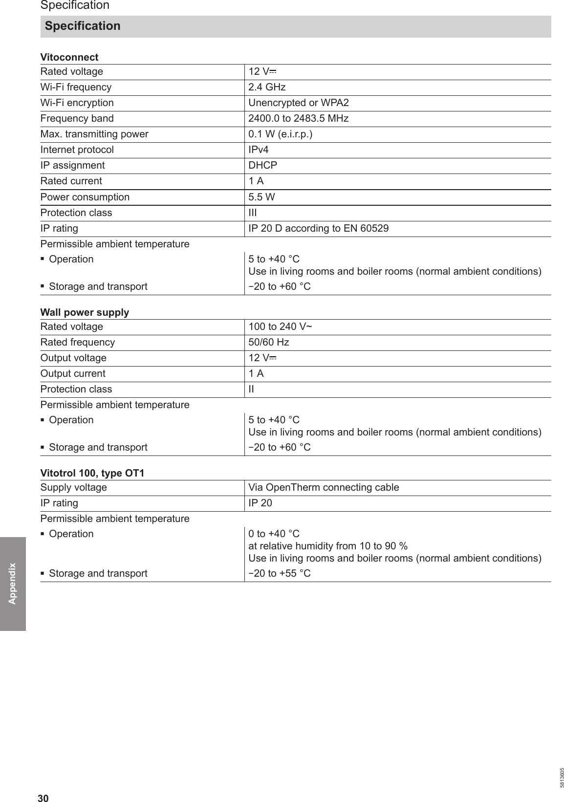
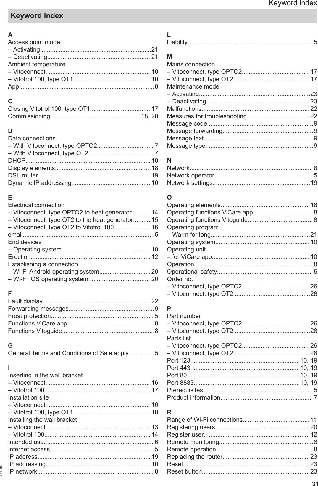
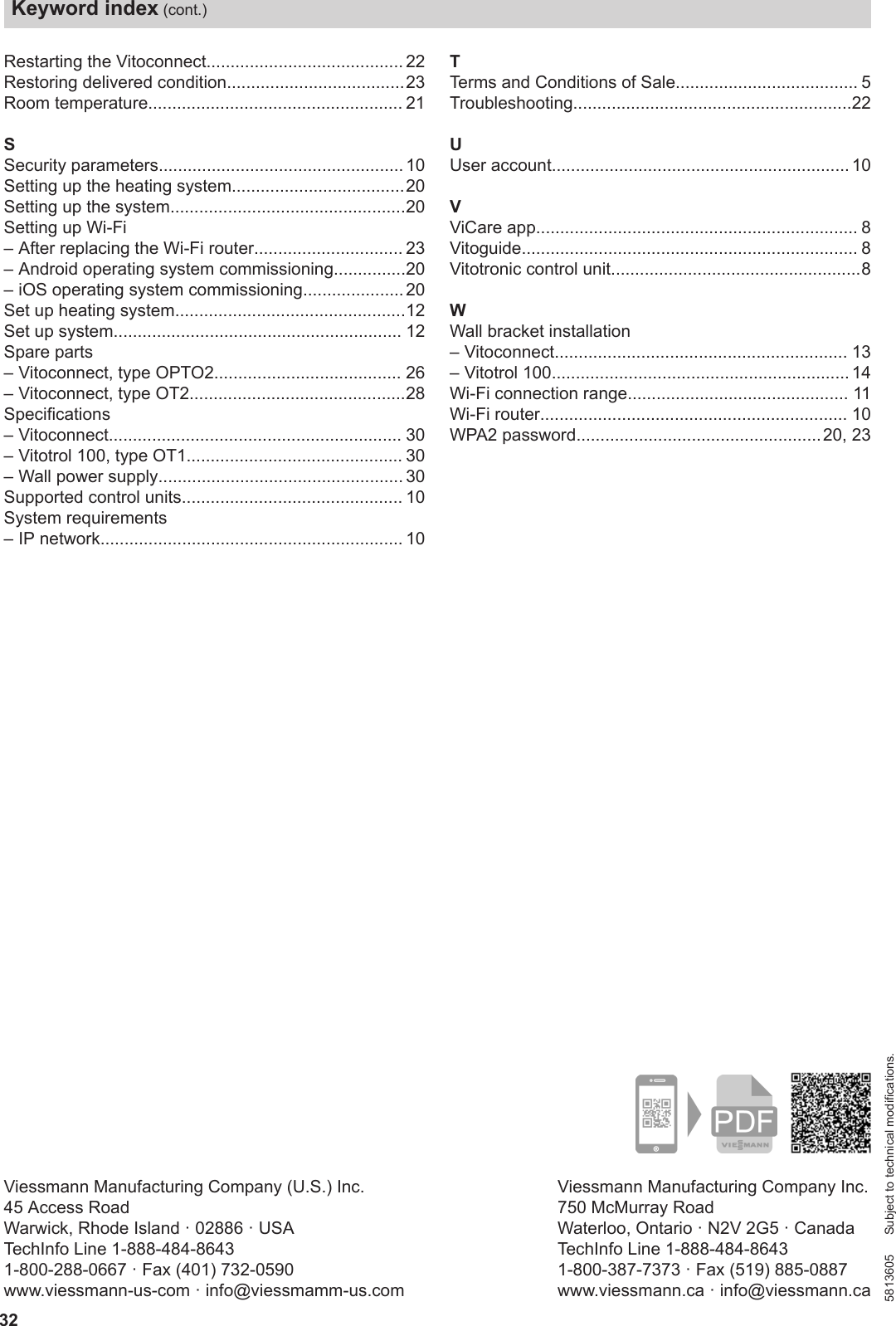
Users Manual
Users Manual
Navigation menu
Upload a User Manual
Namespaces
Wiki Guide
HTML
PDF
Info
Views
User Manual
Discussion / Help
Navigation