Viessmann Elektronik VC0218 Vitoconnect User Manual
Viessmann Elektronik GmbH Vitoconnect Users Manual
Contents
- 1. Users Manual - safety
- 2. Users Manual
Users Manual
Operating instructions
for the system user
VIESMANN
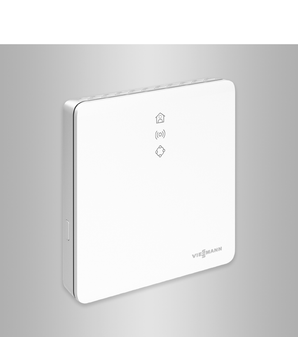
Vitoconnect
Type OPTO2
Type OT2
Communications interface for remote monitoring and remote control of heating
systems over the Internet, for the following user interfaces:
■ViCare app
■Vitoguide
VITOCONNECT
5813605 CA 11/2017 Please keep safe.
2
Please follow these safety instructions closely to
prevent accidents and material losses.
Safety instructions explained
Danger
This symbol warns against the risk of injury.
!Please note
This symbol warns against the risk of material
losses and environmental pollution.
Note
Details identified by the word "Note" contain additional
information.
Target group
These instructions are intended for the persons operat-
ing the system.
Individual sections of this manual describe activities
that are to be executed by qualified contractors.
This appliance can also be operated by children aged
8 years and older, as well as by individuals with
reduced physical, sensory or mental faculties or those
lacking in experience and knowledge, provided that
such individuals are being supervised or have been
instructed in the safe use of this appliance and under-
stand the dangers arising from it.
Danger
The operation of electronic medical aids in par-
ticular, e.g. heart pacemakers, hearing aids and
defibrillators can get disrupted by radio signals.
If such devices are used, direct proximity to
operationally ready wireless components must
be avoided.
Installing and settings
■Make settings and carry out work on the appliance
only in accordance with the instructions in this man-
ual.
■Work on electrical equipment may only be carried
out by a qualified electrician.
■Connect the appliances only to properly installed
sockets.
■When working on the appliance, pull the mains plug.
■Comply with the minimum distances in order to
ensure reliable signal transmission.
System operation
■Operate the appliances in dry internal areas only (not
in bathrooms).
■Do not operate the appliances in areas with a poten-
tially explosive atmosphere.
■Protect the devices from:
–Wetness
–Dust
–Liquids
–Vapours
–Direct sunlight
–Any other direct thermal radiation
■After a power failure or a restart, check the status of
the wireless components.
■Do not touch the power supply with wet hands.
Danger
Damaged appliances endanger your safety.
Check the appliance for external damage. Do
not switch on a damaged appliance.
Auxiliary components and individual parts
For replacements, use original Viessmann parts only
or individual parts approved by Viessmann.
Danger
There is a danger of fire from connecting unsuit-
able power supplies.
Connect only the supplied power supply unit.
Safety instructions
Safety instructions
5813605

3
1. Safety and liability Operational safety .................................................................................. 5
Liability ................................................................................................... 5
2. Information before starting Symbols ................................................................................................. 6
Qualified contractor ................................................................................ 6
Intended use .......................................................................................... 6
Product information ................................................................................ 7
■Data connections with Vitoconnect, type OPTO2 ............................... 7
■Data connections with Vitoconnect, type OT2 .................................... 7
Operation via app .................................................................................. 8
■ViCare app operating functions .......................................................... 8
■ Vitoguide operating functions ...................................................... 8
■Forwarding messages ........................................................................ 9
3. Preparing for installation System requirements ............................................................................. 10
■Supported control units ....................................................................... 10
■IP network ........................................................................................... 10
Installation site ....................................................................................... 10
■Vitoconnect ......................................................................................... 10
■Vitotrol 100, type OT1 ......................................................................... 10
■Ranges ............................................................................................... 11
4. Installation sequence Overview of steps for installation and commissioning ........................... 12
Installing the wall bracket ....................................................................... 13
■Vitoconnect ......................................................................................... 13
■Vitotrol 100, type OT1 ......................................................................... 14
Vitoconnect, connect type OPTO2 to heat generator ............................ 14
Connecting Vitoconnect, type OT2 ........................................................ 15
■Vitoconnect, connecting type OT2 to the heat generator ................... 15
■Vitoconnect, connecting type OT2 to Vitotrol 100 ............................... 16
Closing the device and inserting it into the wall bracket ........................ 16
■Vitoconnect ......................................................................................... 16
■Vitotrol 100, type OT1 ......................................................................... 17
Vitoconnect mains connection ............................................................... 17
5. Commissioning Display and operating elements ............................................................ 18
■Meaning of the LEDs .......................................................................... 19
Checking the network settings ............................................................... 19
Registering users and setting up the heating system ............................ 20
■Android operating system: Setting up Wi-Fi ....................................... 20
■iOS operating system: Setting up Wi-Fi .............................................. 20
6. Operating functions Access point mode ................................................................................ 21
■Activating access point mode ............................................................. 21
■Deactivating access point mode ......................................................... 21
Temporarily adjusting the room temperature ......................................... 21
7. What to do? Measures for troubleshooting ................................................................ 22
Restarting the Vitoconnect ..................................................................... 22
Restoring delivered condition ................................................................ 23
Maintenance mode ................................................................................ 23
■Activating maintenance mode ............................................................ 23
■Deactivating maintenance mode ........................................................ 23
Setting up Wi-Fi after replacing the router ............................................. 23
8. Parts lists Ordering parts ........................................................................................ 25
Parts list Vitoconnect, type OPTO2 ....................................................... 26
Parts list Vitoconnect, type OT2 ............................................................ 28
9. Specification ................................................................................................................ 30
Index
Index
5813605

5
Vitoconnect facilitates communication over the Internet
between the following components and the Viessmann
server:
■Vitotronic control unit (Optolink interface)
■Heat generator with OpenTherm interface
The full range of functions is only available if the fol-
lowing conditions are fulfilled:
■The Vitotronic control units, the heat generator with
OpenTherm interface and the Vitoconnect must be
correctly connected and configured.
■The Vitoconnect is connected to the Internet via a
Wi-Fi router.
■Internet access must be available at all times.
■The user registration has been carried out: see
page 20.
■For messages to be sent even in case of a power
failure, we recommend an uninterruptible power sup-
ply for the Vitoconnect and the Wi-Fi router.
Note
■The heating system and the operability of the mes-
sage channels must be checked at regular intervals.
■To further enhance the operational safety of the
heating system, we recommend planning supple-
mentary measures, such as frost protection or
checking for water damage.
Liability
No liability is accepted for lost profit, missed savings,
or other direct or indirect consequential damage that
arises from the use of Vitoconnect, the Viessmann
server or the software, as well as for damage from
incorrect use. The limitation of liability is not applicable
if the damage is caused wilfully or by gross negli-
gence, or if there is an obligatory liability according to
the product liability law.
The General Terms and Conditions of Sale contained
in the respective latest Viessmann price list apply.
Push messaging and email services are services from
network operators, for which Viessmann is not liable.
In these cases the T&Cs of the respective network
operators apply.
Safety and liability
Operational safety
5813605
Information
6
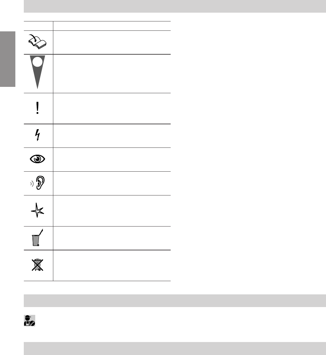
Symbol Meaning
Reference to other document containing
further information
1.
Step in a diagram:
The numbers correspond to the order in
which the steps are carried out.
Warning of material losses and environ-
mental pollution
Live electrical area
Pay particular attention.
■Component must audibly click into place.
or
■Acoustic signal
■Fit new component.
or
■In conjunction with a tool: Clean the sur-
face.
Dispose of component correctly.
Dispose of component at a suitable collec-
tion point. Do not dispose of component in
domestic waste.
Qualified contractor
Activities that may only be carried out by a quali-
fied contractor are marked with this icon.
Work on electrical equipment may only be carried out
by a qualified electrician.
Intended use
In keeping with the intended use, Vitoconnect products
should be installed and operated exclusively in con-
junction with the electronic control units and controllers
of the Viessmann heat and power generators suppor-
ted for this purpose.
Vitoconnect products are designed for operation in
buildings used for residential and business purposes
only. Misuse of the appliances is prohibited and will
result in exclusion of liability (e.g. commercial or indus-
trial use for a purpose other than for control and regu-
lation).
Compliance is required with the installation, service
and operating instructions supplied with the product
and provided online.
Vitoconnect products are to be used exclusively for
monitoring, operation and optimisation of the systems,
using the user and communications interfaces defined
in the printed material of the product. For the commu-
nications interfaces, it must be ensured on-site that for
all the transmission media used, the system require-
ments defined in the product documents are met at all
times (e.g. the required Wi-Fi connection to a Wi-Fi
router).
Information before starting
Symbols
5813605
Information
7
For voltage supply, only the components specified for
this purpose may be used (e.g. wall power supplies).
Note
The appliances are designed exclusively for domestic
or domestic-like use, i.e. even uninstructed persons
can safely operate them.
Product information
Vitoconnect is a wall-mounted Internet interface that
communicates with the boiler control unit of the heat
generators.
■Using an Optolink interface, the Vitoconnect
type OPTO2 can be used for single-boiler systems
without any downstream heating circuits.
■Using an OpenTherm interface, the Vitoconnect
type OT2 can be used for single-boiler systems with-
out any downstream heating circuits.
The Vitoconnect enables remote operation of heating
systems over the Internet. For settings and queries the
ViCare app is used. A qualified contractor can alterna-
tively control the heating system via Vitoguide.
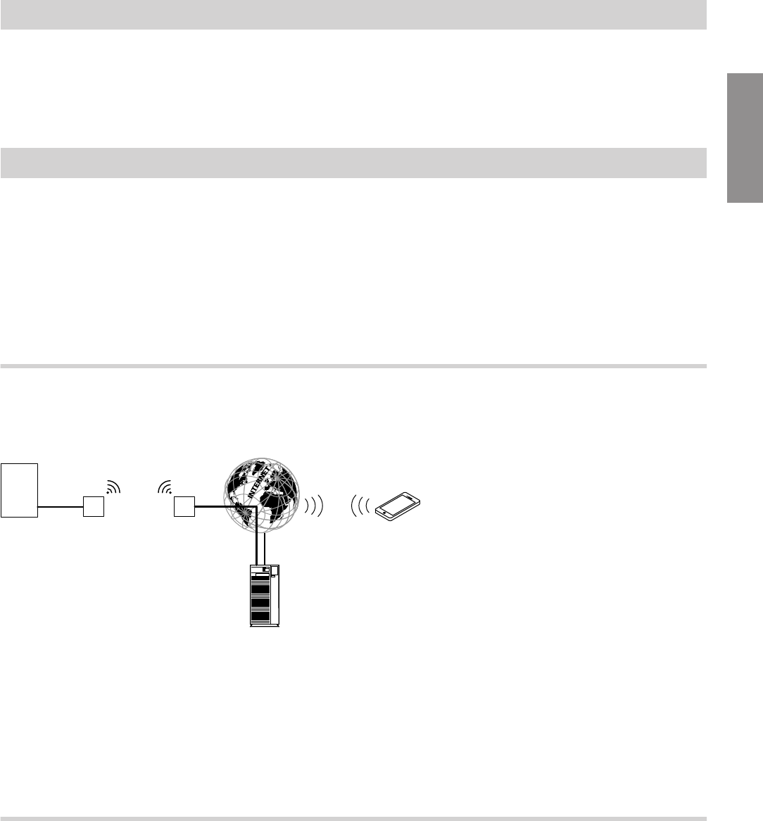
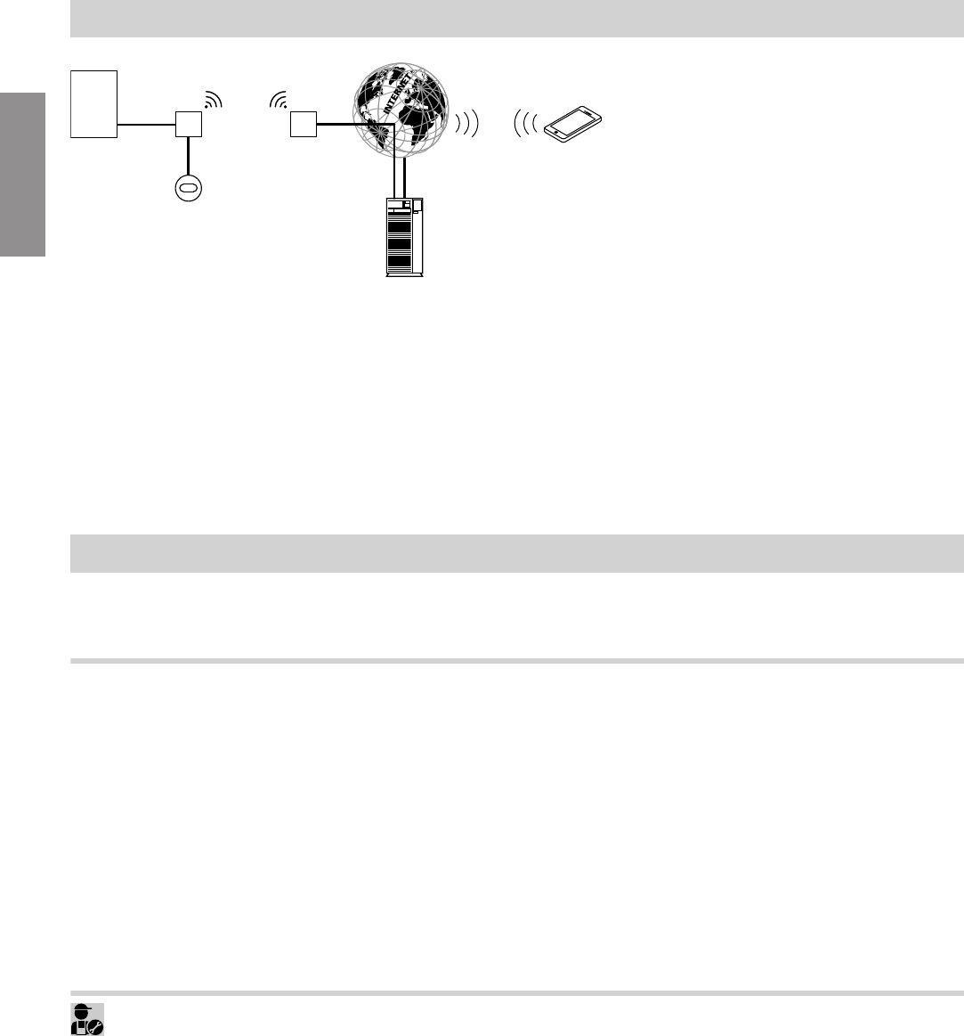
Data connections with Vitoconnect, type OPTO2
In conjunction with heat generators with Optolink inter-
face only
K
BC
A
E
H
G
F
D
Fig. 1
AHeat generator with control unit
BOptolink connecting cable
CVitoconnect, type OPTO2
DWi-Fi
EWi-Fi router (on site)
FSecure Internet connection to the Viessmann
server
GViessmann server
HMobile network
or
Wi-Fi connection
KSmartphone
Data connections with Vitoconnect, type OT2
In conjunction with heat generators with OpenTherm
interface only
Information before starting
Intended use (cont.)
5813605
Information
8
M
BC
A
G
L
K
H
F
D
E
Fig. 2
AHeat generator with control unit
BOpenTherm connecting cable
CVitoconnect, type OT2
DOpenTherm connecting cable
EVitotrol 100, type OT1
FWi-Fi
GWi-Fi router (at the site)
HSecure Internet connection to the Viessmann
server
KViessmann server
LMobile network
or
Wi-Fi connection
MSmartphone
Operation via app
For remote operation of Viessmann heat generators with Optolink interface or OpenTherm interface over IP net-
works.
ViCare app operating functions
■Query the temperatures of the connected heating cir-
cuits.
■Adjust the temperatures and time programs for the
central heating and DHW heating.
■Adjust the heating times by means of a "heating
times wizard".
■Set the comfort and reduced operation using quick
selection buttons ("I am at home for longer" and "I
am travelling").
■Add more users for operating the heating system.
■Save the contact data of your contractor to get in
touch more easily.
■Assign service access to the contractor to have sys-
tem data such as error messages transmitted to the
contractor.
■View heating system error messages in plain text by
means of push messaging.
Note
For further information on the ViCare app see
www.vicare.info
or
App Store and Google Play
Vitoguide operating functions
■Monitoring of the heating system once the system
operator has assigned service access
■Querying the system information of the connected
heating system
■Specification for operating programs, set values and
time programs
■Viewing fault messages in plain text
■Automatic forwarding of fault messages by email
Information before starting
Product information (cont.)
5813605
Information

9
Forwarding messages
Messages that are queued at the heating system,
such as sensor or burner faults, are transmitted to the
Vitoconnect over the OpenTherm or Optolink connect-
ing cable. Vitoconnect transmits these messages to
the Viessmann server. The ViCare app polls the status
of the heating system cyclically and displays the mes-
sages.
Note
Messages of the heating system are only displayed if
the ViCare app is active on the mobile end device.
Content of the messages
■Message type
■Message code
■Message text
Heat generator installation and service instruc-
tions
Information before starting
Operation via app (cont.)
5813605
Information

10
Supported control units
Current overview of the supported control units: see
www.viessmann.com/vitoconnect
IP network
System requirements
■Wi-Fi router with activated Wi-Fi. The Wi-Fi router
must be protected by a sufficiently secure WPA2
password. Unencrypted connections of the Vitocon-
nect to the Wi-Fi router are discouraged.
■Internet connection with "flatrate" (fixed charge with
unlimited time and data) with high availability, i.e.
the Vitoconnect is permanently connected to the
Viessmann server.
■Network (Wi-Fi) with dynamic IP addressing (DHCP,
delivered condition); have an IT professional check
this before commissioning; set up if required.
■Define the routing and security parameters for the IP
network (LAN): open port 80, port 123, port 443 and
port 8883 for directly outgoing connections. Have an
IT professional check this on-site before commis-
sioning; set up if required.
Note
During operation, Vitoconnect sets up a secure Inter-
net connection to the Viessmann server. Connections
of the Vitoconnect with other servers are not possible.
User account
Regardless of the operating unit, the Vitoconnect
requires a valid user account for the Viessmann
server. This account is registered automatically at the
time of commissioning via the ViCare app: see
page 20).
Operating unit for ViCare app
The ViCare app supports the following end devices:
■End devices with Apple iOS operating system
■End devices with Google Android operating system
Note
■Compatible versions: See the App Store or Google
Play
■For further information see www.vicare.info
Message destinations
End device for receiving email, for example computer,
smartphone or tablet PC.
Installation site
Vitoconnect
Type of installation: Wall mounting
■Installation inside a closed building only
■The installation site must be dry and frost-free.
■Ambient temperatures between +5 and +40 °C must
be ensured.
■Distance from the heat generator min. 0.3 m and
max. 2.5 m
■230 V/50 Hz Schuko socket
or
US/CA: 120 V/60 Hz outlet
max. 1.5 m from the installation site
■Internet access with an adequate Wi-Fi signal
Note
The Wi-Fi signal can be strengthened with a com-
mercially available Wi-Fi repeater.
Note
■Observe the lengths of the supplied connecting
cables when selecting the installation site.
■Keep the distance between the Vitoconnect and the
Wi-Fi router as small as possible to ensure a good
Wi-Fi connection.
Connecting cables Length
Wall power supply with connecting ca-
ble
1.5 m
Optolink or OpenTherm connecting ca-
ble to connect the Vitoconnect to the
boiler control unit
3 m
Vitotrol 100, type OT1
Type of installation: Wall mounting
■On an inner wall in the main living room, approx.
1.5 m from the floor
■The installation site must be dry and frost-free.
■Ensure ambient temperatures between 0 and
+40 °C.
■
■Not in the immediate vicinity of doors and windows
Preparing for installation
System requirements
5813605
Installation

11
■Not above radiators
■Not in cupboards, niches etc.
■Not near heat sources (direct sunlight, chimney, TV
etc.)
Ranges
The range of Wi-Fi connections can be reduced by
walls, ceilings and furniture. The strength of the Wi-Fi
signal gets reduced and reception can be disturbed.
Range reduction:
■Wi-Fi signals get attenuated on the way from the
transmitter to the receiver, for example, through the
air and when penetrating walls.
■Wi-Fi signals are reflected by metallic parts,
for example, reinforcement in walls, metal foils of
heat insulation and metallised thermo-glass for heat
insulation.
■Wi-Fi signals are cut off by supply blocks and lift
shafts.
■Wi-Fi signals are disturbed by devices that also
work with high-frequency signals. Keep a distance of
min. 2 m to the following devices:
–Computers
–Audio and video systems
–Radio signals
–Electronic transformers
–Ballast
Note
We recommend keeping the distance between the
Vitoconnect and the Wi-Fi router as small as possible
to ensure a good Wi-Fi connection.
Preparing for installation
Installation site (cont.)
5813605
Installation
12
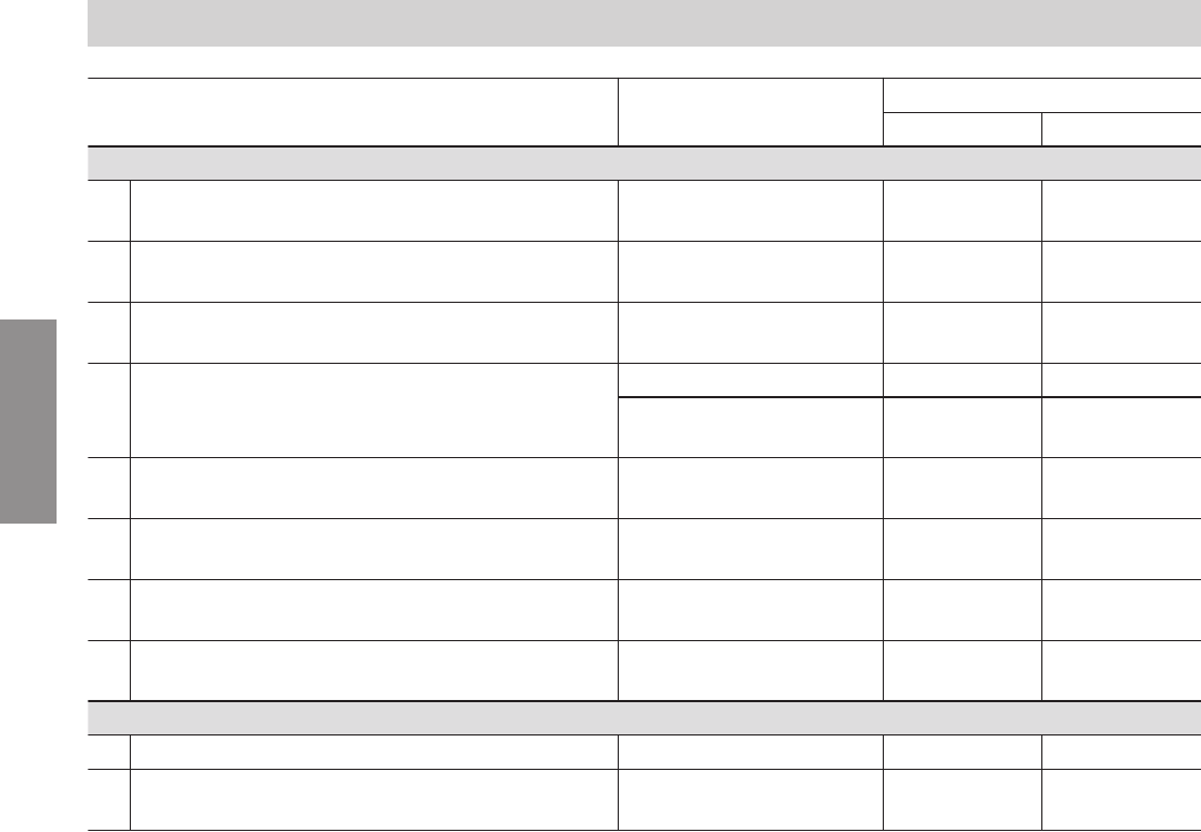
Work steps Responsible party Page
Type OPTO2 Type OT2
Installation
1 Check the system requirements. Heating contractor
IT professional
10 10
2 Install the wall bracket for the Vitoconnect. Heating contractor
System operator
13 13
3 Install the wall bracket of the Vitotrol 100. Heating contractor
System operator
— 14
4 Connect the Vitoconnect to the heat generator. Heating contractor — 15
Heating contractor
System operator
14 —
5 Connect the Vitoconnect and the Vitotrol 100. Heating contractor
System operator
— 16
6 Insert the Vitoconnect in the wall bracket. Heating contractor
System operator
16 16
7 Insert the Vitotrol 100 in the wall bracket. Heating contractor
System operator
— 17
8 Set up the Vitoconnect mains connection. Heating contractor
System operator
17 17
Commissioning
9 Check the network settings. IT professional 19 19
10 Register the user and set up the heating sys-
tem .
Heating contractor
System operator
20 20
Installation sequence
Overview of steps for installation and commissioning
5813605
Installation
13
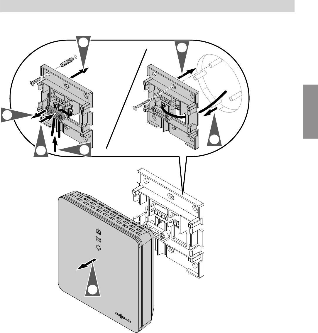
Vitoconnect
1.
2x
2x
2.
3.
3.
2.
5. 4.
Fig. 3
Installation sequence
Installing the wall bracket
5813605
Installation
14
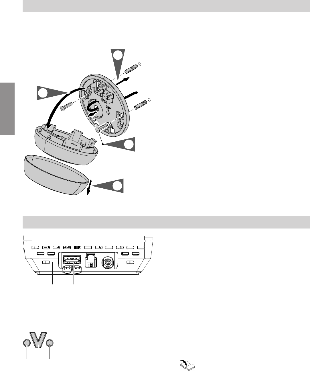
Vitotrol 100, type OT1
In conjunction with Vitoconnect, type OT2 only
1.
2.
3.
4.
Fig. 4
Vitoconnect, connect type OPTO2 to heat generator
CA
Fig. 5
AVitoconnect
CUSB connection
1. Insert the USB connector of the Optolink/USB con-
necting cable into the socket C of the Vitoconnect.
E FD
Fig. 6
DFault display
EOptolink interface
FOperation indicator
2. Connect the Optolink plug of the Optolink/USB
connecting cable with the Optolink interface E at
the control unit of the heat generator.
Connection to the heat generator
Operating instructions of the heat generator
Installation sequence
Installing the wall bracket (cont.)
5813605
Installation
15
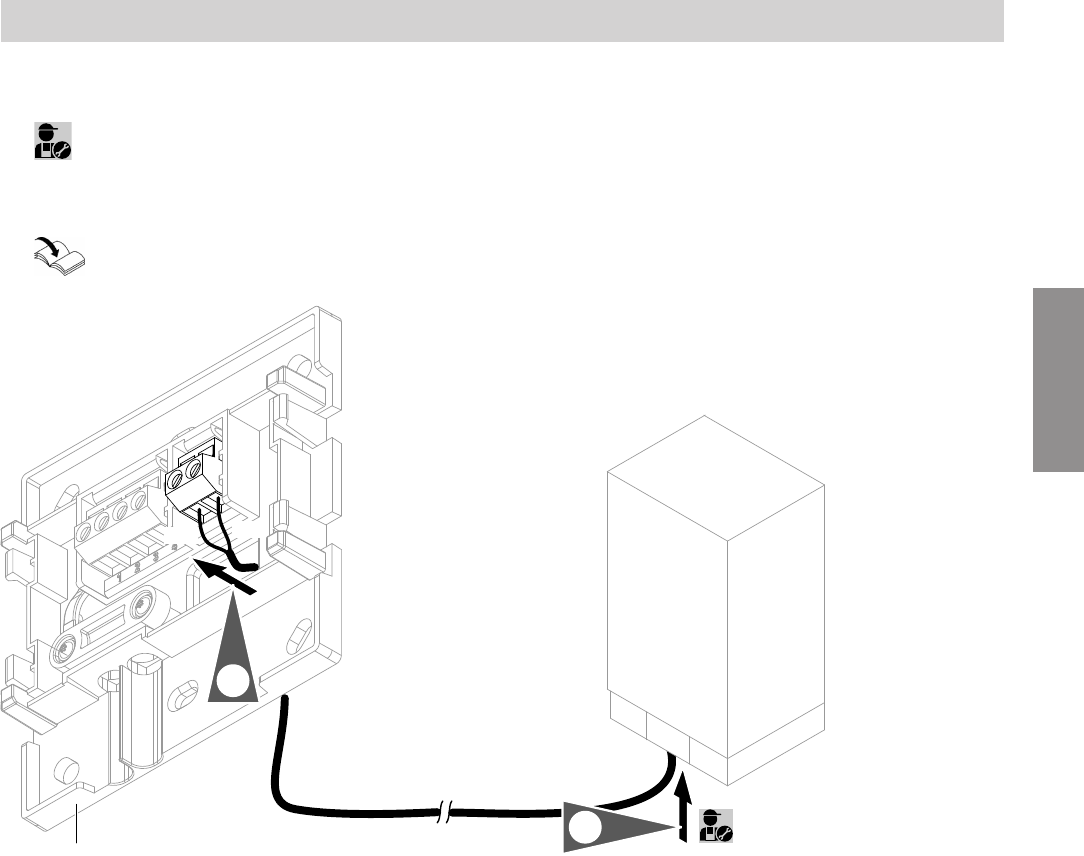
Vitoconnect, connecting type OT2 to the heat generator
1.
Connect the OpenTherm connecting cable to the
heat generator.
Heat generator installation and service
instructions
A
2.
56
OT+ OT-
1.
Fig. 7
AVitoconnect
Installation sequence
Connecting Vitoconnect, type OT2
5813605
Installation
16
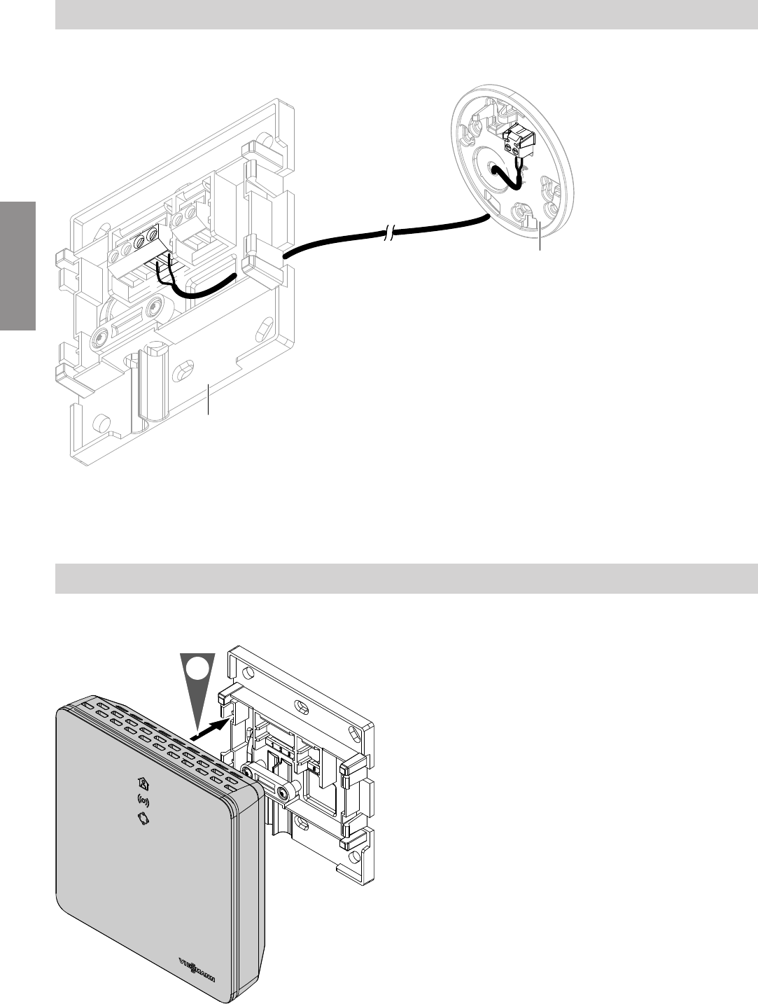
Vitoconnect, connecting type OT2 to Vitotrol 100
C
34
-
+
A
-
+
AB
Fig. 8
AVitoconnect
CVitotrol 100, type OT1
Closing the device and inserting it into the wall bracket
Vitoconnect
1.
Fig. 9
Installation sequence
Connecting Vitoconnect, type OT2 (cont.)
5813605
Installation
17
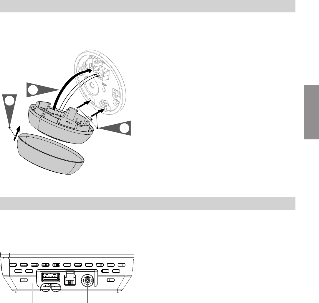
Vitotrol 100, type OT1
In conjunction with Vitoconnect, type OT2 only.
8.1.
3.
2.
Fig. 10
Vitoconnect mains connection
The socket for the wall power supply must be located
in the vicinity of the appliance and be freely accessible.
On-site fusing of the socket: max. 16 A (US, CA: max.
20 A).
CA
Fig. 11
AVitoconnect
CVoltage supply connection
1. Insert the barrel connector of the wall power supply
into the connection C of the Vitoconnect.
2. Insert the wall power supply for Vitoconnect into
the socket.
Installation sequence
Closing the device and inserting it into the… (cont.)
5813605
Installation
18
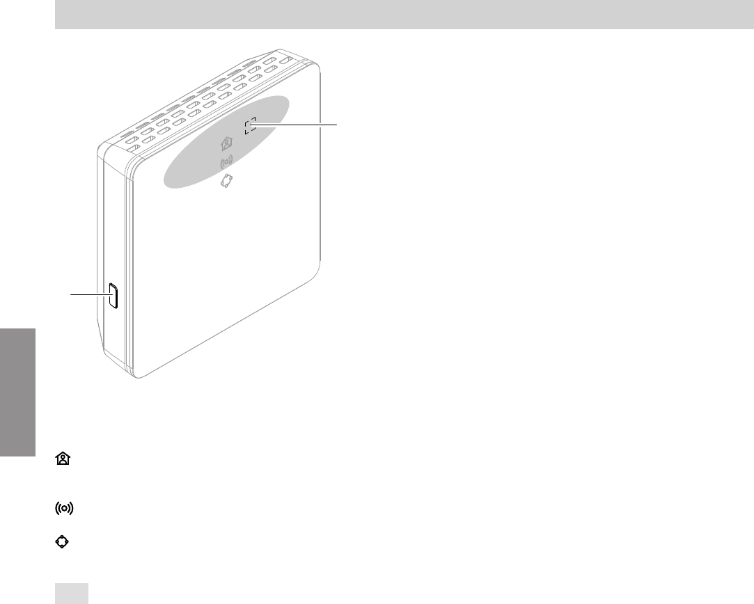
B
A
Fig. 12
AOperating button
BReset button
LED indicates the state of the communication with
the heat generator and the current operating sta-
tus.
LED indicates the state of the communication with
the Wi-Fi and the Viessmann server.
LED indicates the system functions (maintenance
mode, restart, update, error).
= Actuation area of the operating button A
Commissioning
Display and operating elements
5813605
Commissioning
19
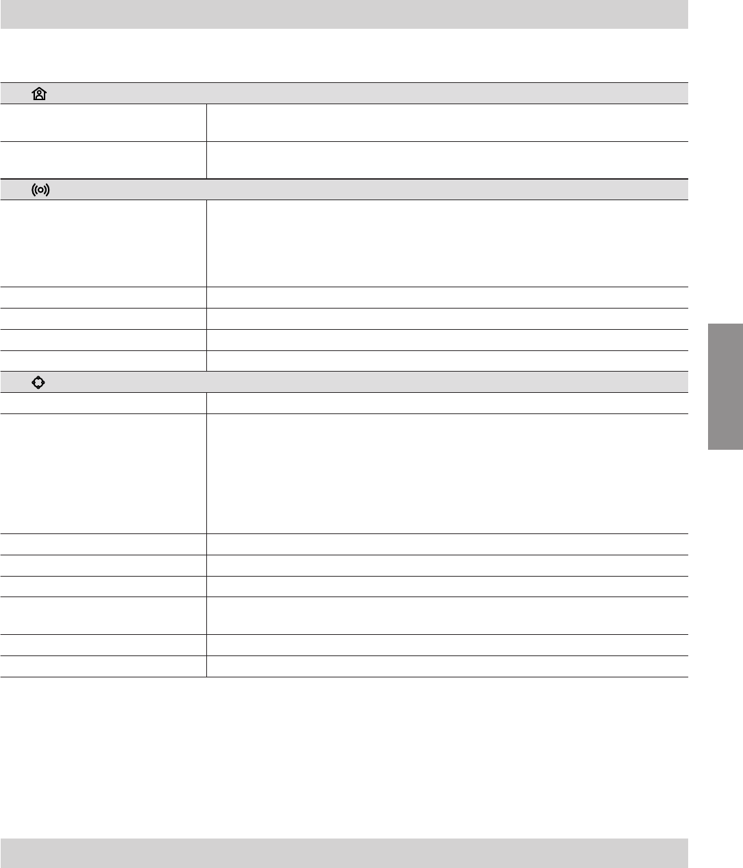
Meaning of the LEDs
LED – communication with the heat generator and operating status
Slowly pulsating in white. Connection to Vitoconnect established successfully:
Operation program "I am at home for longer" is active.
Illuminated in white. Connection to Vitoconnect established successfully:
Central heating according to time program
LED – communication with the Viessmann server
Illuminated in green. Connection between Vitoconnect and Viessmann server established success-
fully:
■Access point mode is active.
Or
■Vitoconnect is starting.
Pulsating in yellow. Connection between Vitoconnect and Wi-Fi router failed: see page 22.
Illuminated in yellow. No Internet connection: see page 22
Rapidly flashes red. Firmware or hardware error: see page 22
Illuminated in red. Connection between Vitoconnect and Viessmann server failed: see page 22
LED – system functions
Pulsating in green. Connection between Vitoconnect and ViCare thermostat is being established
Illuminated in green. ■Vitoconnect is starting.
Or
■A new Vitoconnect firmware is being installed.
!Please note
Do not damage the Vitoconnect.
During firmware installation, do not disconnect the Vitoconnect from
the mains supply.
Flashes yellow. Communication error with the Vitotrol 100, type OT1: see page 22
Rapidly flashes yellow. No connection to the heat generator: see page 22
Pulsating in red. Maintenance mode (no data transmission): see page 23
Flashes red. Vitoconnect has been reset to the delivered condition and can be commis-
sioned once again.
Rapidly flashes red. Firmware or hardware error: see page 22
Illuminated in red. Error in the control unit of the heat generator: see page 22
Note
Slowly pulsating: The LED flashes once every 4 s
bright and darker.
Pulsating: The LED flashes once every second
bright and darker.
Flashing: The LED is on once every second.
Rapid flashing: The LED is on twice every second.
Checking the network settings
Have the following settings on the Wi-Fi router
checked and adjusted by an IT professional, if
required:
■Dynamic IP addressing must be active.
■Port 80, port 123, port 443 and port 8883 must be
open for outgoing connections.
Commissioning
Display and operating elements (cont.)
5813605
Commissioning
20
1. Download the ViCare app from the App Store or
Google Play and install it.
Note
Apple iPad and Android tablet PCs are not suppor-
ted.
2. Start the ViCare app and tap "Create account".
3. Follow the instructions in the ViCare app.
4. Scan the QR code.
Or
Enter the numbers for "S/N" and "ID".
Note
QR code, "S/N" and "ID": See the supplied Vito-
connect sticker.
5. Set up the Vitoconnect Wi-Fi: see the next chapter.
6. Connect the Vitoconnect to your home network.
The Vitoconnect and the ViCare app are set up
when the LED is illuminated in white: See chap-
ter "Display and operating elements".
Android operating system: Setting up Wi-Fi
Automatic connection with "Vitoconnect<xxxx>" Wi-
Fi.
iOS operating system: Setting up Wi-Fi
1. Open the Wi-Fi settings of your smartphone.
2. Connect your smartphone to the "Vitocon-
nect<xxxx>" Wi-Fi.
Note
The WPA2 password will automatically be in the
clipboard.
3. Insert the WPA2 password from the clipboard.
Note
The WPA2 password can be found on the supplied
sticker.
Commissioning
Registering users and setting up the heating system
5813605
Commissioning
21
Activate the access point mode, for example, after
replacing the Wi-Fi router or to allow service queries
from the contractor.
Activating access point mode
Press the operating button A for longer than 5 s, but
not longer than 30 s: See chapter "Display and operat-
ing elements".
LED illuminated in green:
Access point mode is active.
Deactivating access point mode
1. Access point mode is automatically deactivated
after 5 min.
Or
2. Once again press the operating button A for lon-
ger than 5 s, but not longer than 30 s: See chapter
"Display and operating elements".
LED not illuminated any more.
Access point mode is deactivated.
Temporarily adjusting the room temperature
If you wish to heat your premises to a higher tempera-
ture for a limited time, activate the "I am at home for
longer" operating program.
You have two options for setting the operating pro-
gram:
Press the operating button A for max. 3 s: See chap-
ter "Display and operating elements".
Or
Set the operating program via the ViCare app.
Operating functions
Access point mode
5813605
Service
22
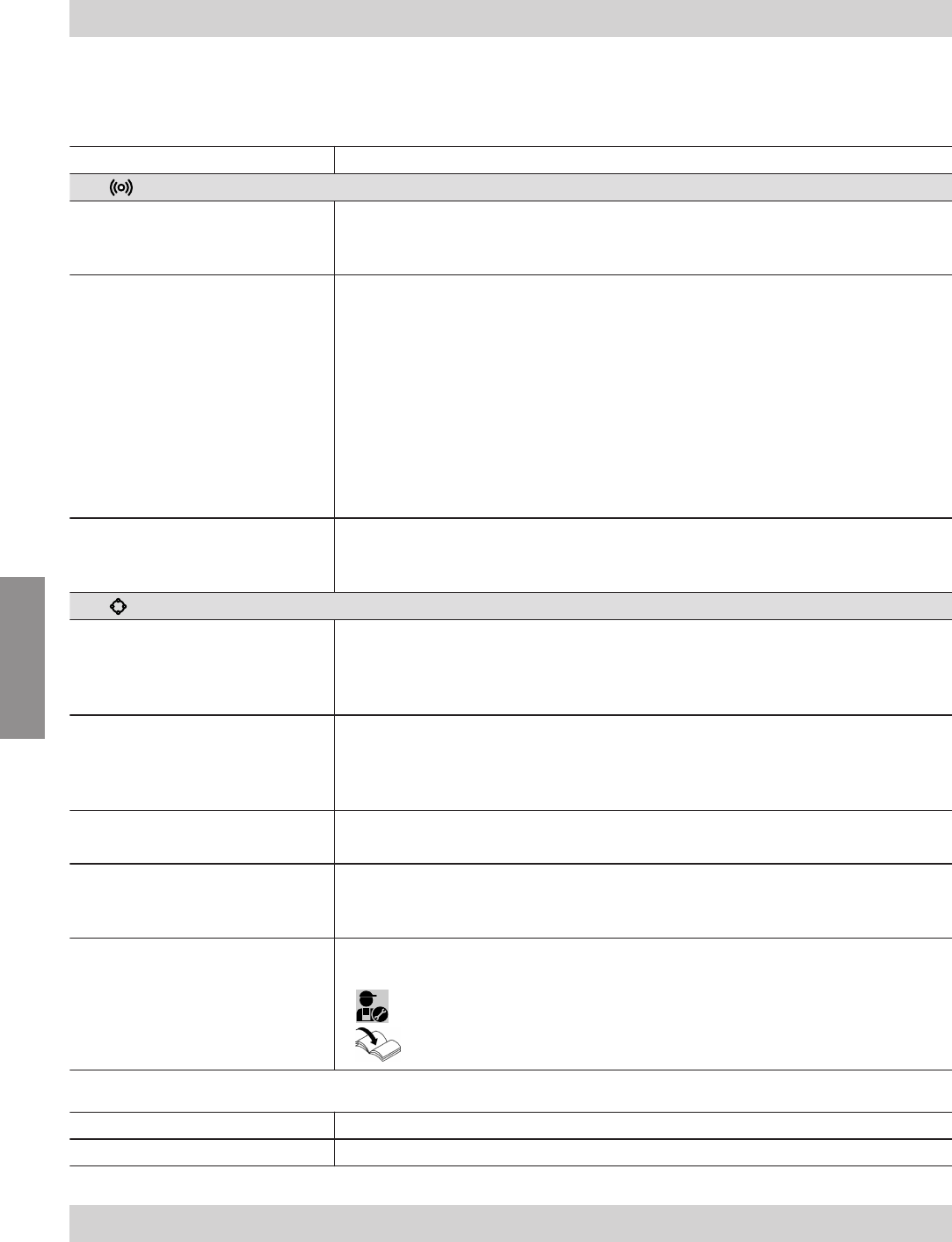
Malfunctions at the Vitoconnect are shown by various
LED indications: see page 18.
Malfunctions with LED indications
Type of fault and measures
LED
Pulsating in yellow. Connection between Vitoconnect and Wi-Fi router failed:
■Check the password at the time of Wi-Fi commissioning.
■Restart the Vitoconnect: see page 22.
Illuminated in yellow.
Or
Illuminated in red.
No Internet connection or No connection to the Viessmann server
■No Wi-Fi connection
–Check the network setting at the time of Wi-Fi commissioning.
–Check the password at the time of Wi-Fi commissioning.
■Inadequate Wi-Fi signal strength
–Change the installation site of the Vitoconnect: see page 10
■The Wi-Fi connection is active, but there is no Internet connection
–Check the Internet connection with another device, e.g. a laptop.
If an Internet connection cannot be established with other devices either,
have your network settings checked by an IT professional.
■Restart the Vitoconnect: see page 22.
Rapidly flashes red. Firmware or hardware error
■Restart the Vitoconnect: see 22.
■Replace the Vitoconnect, if required.
LED
Flashes yellow. Communication error with the Vitotrol 100, type OT1:
■Check the OpenTherm connecting cable to the Vitotrol 100, type OT1: see
page 16
■Restart the Vitoconnect: see page 22
Rapidly flashes yellow. No connection to the heat generator
■Check the plug-and-socket connections (Optolink, USB).
■Check the connecting cable.
■Restart the Vitoconnect: see page 22.
Pulsating in red. Maintenance mode (no data transmission)
■Deactivate the maintenance mode: see page 23
Rapidly flashes red. Firmware or hardware error
■Restart the Vitoconnect: see page 22
■Replace the Vitoconnect, if required.
Illuminated in red. Error in the control unit of the heat generator
■Observe the message in the ViCare app.
■:
Heat generator installation and service instructions
Malfunctions without LED indications
Fault Measures
All Vitoconnect LEDs are off. Check the mains connection and wall power supply of the Vitoconnect.
Restarting the Vitoconnect
After rectifying the fault, the Vitoconnect has to be
restarted.
What to do?
Measures for troubleshooting
5813605
Service
23
Press the Reset button B and the operating button A
for approx. 15 s: See chapter "Display and operating
elements".
LED illuminated in white.
Restoring delivered condition
1. Press the Reset button B for approx. 30 s: see
page 18.
LED flashes red.
2. Press the Reset button B once again within 5 s.
LED not illuminated any more.
The Vitoconnect is restarting and resumes the
delivered condition.
Maintenance mode
This function suppresses the transmission of mes-
sages from the heating system to the Viessmann
server, e.g. during maintenance work on the heating
system.
Activating maintenance mode
Press the Reset button B for approx. 5 s to 15 s: see
page 18
LED pulsating in red.
Maintenance mode is activated.
Note
The maintenance mode does not stop automatically
but has to be deactivated.
Deactivating maintenance mode
Press the Reset button B once again for approx. 5 s
to 15 s: see page 18
LED not illuminated any more.
Maintenance mode is deactivated.
Setting up Wi-Fi after replacing the router
1. Activate the Vitoconnect access point mode: see
page 21
2. Open the Wi-Fi settings of your smartphone.
3. Connect your smartphone to the "Vitocon-
nect<xxxx>" Wi-Fi.
4. Enter the WPA2 password.
Note
The WPA2 password can be found on the supplied
sticker.
5. Use the Internet browser on your smartphone to
access http://vitoconnect.gateway
6. On the starting page, select "Select router".
7. Follow the instructions on the Internet page.
8. Deactivate the Vitoconnect access point mode: see
page 21
What to do?
Restarting the Vitoconnect (cont.)
5813605
Service

24
What to do?
Setting up Wi-Fi after replacing the router (cont.)
5813605
Service

25
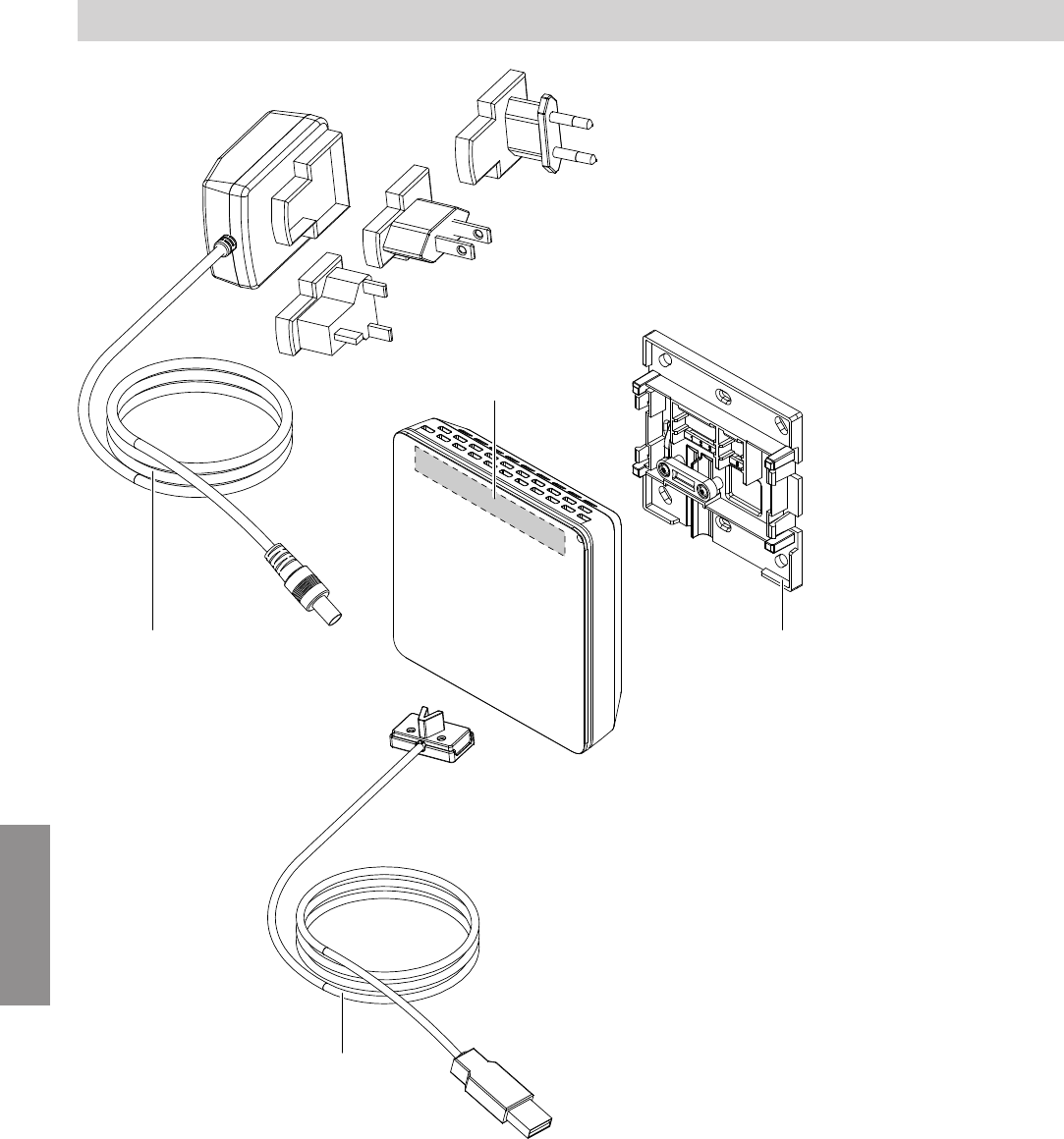
The following details are required when ordering parts:
■Order no. (see type plate A)
■Item number of the individual part (from this parts
list)
Parts lists
Ordering parts
5813605
Components
26
0001 0002
0003
A
Fig. 13
AVitoconnect type plate (on the rear side of the Vito-
connect)
Parts lists
Parts list Vitoconnect, type OPTO2
5813605
Components

27
Item Part
0001 Wall power supply
0002 Wall bracket
0003 USB/Optolink connecting cable
Parts lists
Parts list Vitoconnect, type OPTO2 (cont.)
5813605
Components
28
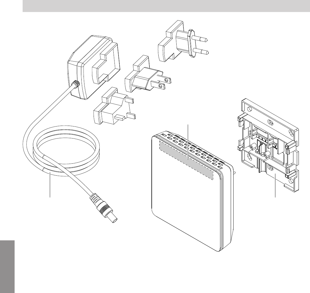
0002
0001
A
Fig. 14
AVitoconnect type plate (on the rear side of the Vito-
connect)
Parts lists
Parts list Vitoconnect, type OT2
5813605
Components
29
Item Part
0001 Wall power supply
0002 Wall bracket
Parts lists
Parts list Vitoconnect, type OT2 (cont.)
5813605
Components

30
Vitoconnect
Rated voltage 12 V
Wi-Fi frequency 2.4 GHz
Wi-Fi encryption Unencrypted or WPA2
Frequency band 2400.0 to 2483.5 MHz
Max. transmitting power 0.1 W (e.i.r.p.)
Internet protocol IPv4
IP assignment DHCP
Rated current 1 A
Power consumption 5.5 W
Protection class III
IP rating IP 20 D according to EN 60529
Permissible ambient temperature
■Operation 5 to +40 °C
Use in living rooms and boiler rooms (normal ambient conditions)
■Storage and transport −20 to +60 °C
Wall power supply
Rated voltage 100 to 240 V~
Rated frequency 50/60 Hz
Output voltage 12 V
Output current 1 A
Protection class II
Permissible ambient temperature
■Operation 5 to +40 °C
Use in living rooms and boiler rooms (normal ambient conditions)
■Storage and transport −20 to +60 °C
Vitotrol 100, type OT1
Supply voltage Via OpenTherm connecting cable
IP rating IP 20
Permissible ambient temperature
■Operation 0 to +40 °C
at relative humidity from 10 to 90 %
Use in living rooms and boiler rooms (normal ambient conditions)
■Storage and transport −20 to +55 °C
Specification
Specification
5813605
Appendix

31
A
Access point mode
– Activating.................................................................21
– Deactivating............................................................ 21
Ambient temperature
– Vitoconnect............................................................. 10
– Vitotrol 100, type OT1............................................. 10
App...............................................................................8
C
Closing Vitotrol 100, type OT1................................... 17
Commissioning.....................................................18, 20
D
Data connections
– With Vitoconnect, type OPTO2................................. 7
– With Vitoconnect, type OT2...................................... 7
DHCP......................................................................... 10
Display elements........................................................18
DSL router..................................................................19
Dynamic IP addressing.............................................. 10
E
Electrical connection
– Vitoconnect, type OPTO2 to heat generator........... 14
– Vitoconnect, type OT2 to the heat generator.......... 15
– Vitoconnect, type OT2 to Vitotrol 100..................... 16
email.............................................................................5
End devices
– Operating system.................................................... 10
Erection...................................................................... 12
Establishing a connection
– Wi-Fi Android operating system.............................. 20
– Wi-Fi iOS operating system:................................... 20
F
Fault display............................................................... 22
Forwarding messages..................................................9
Frost protection............................................................ 5
Functions ViCare app...................................................8
Functions Vitoguide......................................................8
G
General Terms and Conditions of Sale apply...............5
I
Inserting in the wall bracket
– Vitoconnect............................................................. 16
– Vitotrol 100.............................................................. 17
Installation site
– Vitoconnect............................................................. 10
– Vitotrol 100, type OT1............................................. 10
Installing the wall bracket
– Vitoconnect............................................................. 13
– Vitotrol 100.............................................................. 14
Intended use................................................................ 6
Internet access.............................................................5
IP address.................................................................. 19
IP addressing............................................................. 10
IP network.................................................................... 8
L
Liability......................................................................... 5
M
Mains connection
– Vitoconnect, type OPTO2....................................... 17
– Vitoconnect, type OT2.............................................17
Maintenance mode
– Activating.................................................................23
– Deactivating............................................................ 23
Malfunctions............................................................... 22
Measures for troubleshooting.....................................22
Message code..............................................................9
Message forwarding.....................................................9
Message text................................................................9
Message type...............................................................9
N
Network........................................................................ 8
Network operator..........................................................5
Network settings.........................................................19
O
Operating elements....................................................18
Operating functions ViCare app................................... 8
Operating functions Vitoguide...................................... 8
Operating program
– Warm for long..........................................................21
Operating system....................................................... 10
Operating unit
– for ViCare app......................................................... 10
Operation..................................................................... 8
Operational safety........................................................ 5
Order no.
– Vitoconnect, type OPTO2....................................... 26
– Vitoconnect, type OT2.............................................28
P
Part number
– Vitoconnect, type OPTO2....................................... 26
– Vitoconnect, type OT2.............................................28
Parts list
– Vitoconnect, type OPTO2....................................... 26
– Vitoconnect, type OT2.............................................28
Port 123................................................................10, 19
Port 443................................................................10, 19
Port 80..................................................................10, 19
Port 8883..............................................................10, 19
Prerequisites................................................................ 5
Product information...................................................... 7
R
Range of Wi-Fi connections....................................... 11
Registering users....................................................... 20
Register user..............................................................12
Remote monitoring.......................................................8
Remote operation.........................................................8
Replacing the router...................................................23
Reset..........................................................................23
Reset button...............................................................23
Keyword index
Keyword index
5813605

32
Restarting the Vitoconnect......................................... 22
Restoring delivered condition.....................................23
Room temperature..................................................... 21
S
Security parameters................................................... 10
Setting up the heating system....................................20
Setting up the system.................................................20
Setting up Wi-Fi
– After replacing the Wi-Fi router............................... 23
– Android operating system commissioning...............20
– iOS operating system commissioning..................... 20
Set up heating system................................................12
Set up system............................................................ 12
Spare parts
– Vitoconnect, type OPTO2....................................... 26
– Vitoconnect, type OT2.............................................28
Specifications
– Vitoconnect............................................................. 30
– Vitotrol 100, type OT1............................................. 30
– Wall power supply................................................... 30
Supported control units.............................................. 10
System requirements
– IP network............................................................... 10
T
Terms and Conditions of Sale...................................... 5
Troubleshooting..........................................................22
U
User account.............................................................. 10
V
ViCare app................................................................... 8
Vitoguide...................................................................... 8
Vitotronic control unit....................................................8
W
Wall bracket installation
– Vitoconnect............................................................. 13
– Vitotrol 100.............................................................. 14
Wi-Fi connection range.............................................. 11
Wi-Fi router................................................................ 10
WPA2 password...................................................20, 23
Viessmann Manufacturing Company Inc.
750 McMurray Road
Waterloo, Ontario · N2V 2G5 · Canada
TechInfo Line 1-888-484-8643
1-800-387-7373 · Fax (519) 885-0887
www.viessmann.ca · info@viessmann.ca
Viessmann Manufacturing Company (U.S.) Inc.
45 Access Road
Warwick, Rhode Island · 02886 · USA
TechInfo Line 1-888-484-8643
1-800-288-0667 · Fax (401) 732-0590
www.viessmann-us-com · info@viessmamm-us.com
5813605 Subject to technical modifications.
Keyword index (cont.)
