Vigil Health Solutions ZRX Vitality Wireless Receiver (ZRX) User Manual The Vigil Care System
Vigil Health Solutions Inc Vitality Wireless Receiver (ZRX) The Vigil Care System
manual
Vigil Vitality Wireless Receiver - Manual
Vitality Wireless Receiver (ZRX)
Manual
Vigil Health Solutions Inc. dedicated to improving seniors' quality of life through creative technology.
Page 1 of 2
Revised: 2011-12-15
Vigil Health Solutions Inc. 2102 - 4464 Markham Street * Victoria, BC * Canada * V8Z 7X8. Phone: (250) 383.6900 * (877) 850.1122 Fax: (250) 383.6999 Web: www.vigil.com
© Vigil Health Solutions Inc.
Description
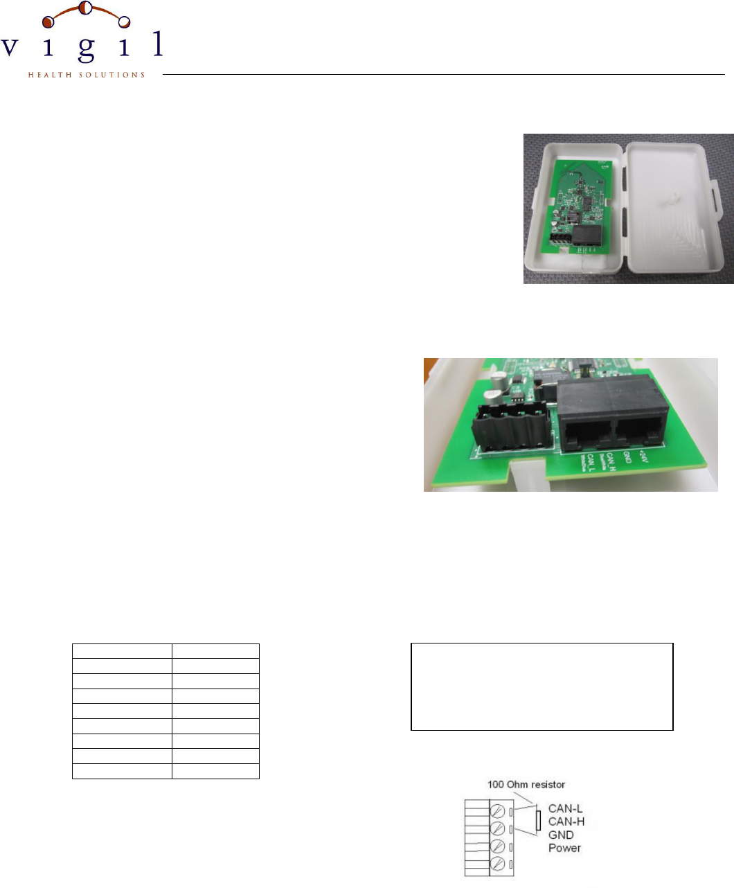
The Vigil Vitality Wireless Receiver (ZRX) is used to receive transmissions from wireless
devices and communicate the data back to the central computer. The Vitality Wireless
Receiver operates on the 2.4GHz IEEE 802.15.4 wireless platform. The ZRX is
connected to the network via low voltage cable (CAT5 or similar) which carries both the
data and power so that no additional power outlets are required at the locations of the
wireless receivers. The cable is terminated at the ZRX with RJ45 modular plugs or on the
screw terminal connector depending on system configuration. One ZRX covers a radius
of approximately 30-50 feet depending on building construction.
Wiring Instructions
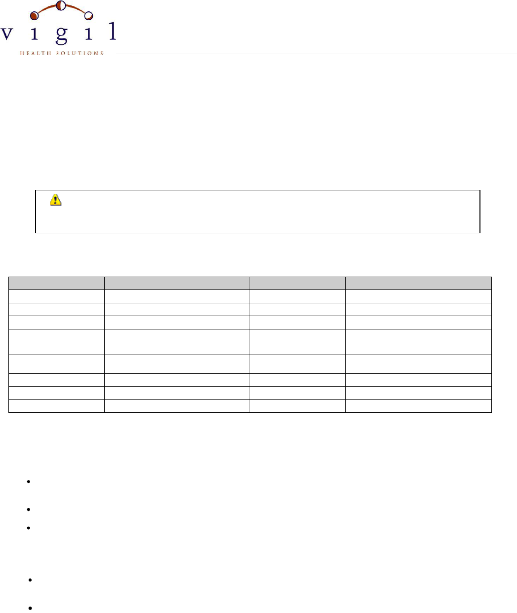
1. There are two options for wiring the ZRX depending on your
system configuration. Use the two RJ45 sockets when using
CAT5 cable for the installation. Use the one 4-pin screw
terminal connector when using 2 pair (4 conductor) 20AWG
stranded cable.
2. Ensure cables are labelled as IN and OUT.
3. For CAT5 applications, terminate the incoming and outgoing
CAT5 cable in RJ45 modular plugs as shown in Figure 1.
4. For 4 conductor cable applications, terminate the both the incoming and outgoing cable in the 4-pin screw terminal
connector in the order shown in Figure 2. Note that there will be two white/blue conductors (in and out) in the CAN L
terminal, two blue conductors in the CAN H terminal, etc.
5. For EOL (End of Line) device ONLY: Add a 100Ohm resister across the CANHI and CANLOW wires (Blue and White
Blue terminals) as shown in Figure 3.
Conductor
Use
White/Blue
CAN L
Blue
CAN H
Green
GND
White/Brown
GND
Brown
GND
White/Orange
+24V
Orange
+24V
White/Green
+24V
From Left to Right:
CAN L White/Blue
CAN H Blue
GND Green/WhiteBrown/Brown
+24V WhiteOrange/Orange/WhiteGreen
Figure 1. RJ45 Modular Plug Wiring
Figure 2. 4-pin Screw Terminal Wiring
Figure 3. End of Line Termination
Vigil Vitality Wireless Receiver - Manual
Vitality Wireless Receiver (ZRX)
Manual
Vigil Health Solutions Inc. dedicated to improving seniors' quality of life through creative technology.
Page 2 of 2
Revised: 2011-12-15
Vigil Health Solutions Inc. 2102 - 4464 Markham Street * Victoria, BC * Canada * V8Z 7X8. Phone: (250) 383.6900 * (877) 850.1122 Fax: (250) 383.6999 Web: www.vigil.com
© Vigil Health Solutions Inc.
Mounting Instructions
Screw mount to wall or ceiling using mounting holes and appropriate mounting hardware for location. Mounting hardware
not supplied. Keep metal screws away from antenna side of circuit board. The antenna is located on the opposite end of
the board from the connectors.
Receivers are typically mounted above the ceiling tile in a corridor. Receivers may also be mounted below the ceiling or
on the ceiling.
Specifications
PHYSICAL
ELECTRICAL
Height
163mm (6.4")
Operating Voltage
10-40V DC
Width
108mm (4.25")
Input Voltage
24V
Depth
48mm (1.9")
Standing Current
8mA, 28.5mA burst
Enclosure Material
White Plastic
Connections
RJ45 modular socket or 4 pin screw
terminal connector
Mounting Method
Screw in drywall
Cable
CAT5E 4 Pair 24AWG or 2 pair
20AWG stranded
Temperature Ratings
Operating:
0°C to 50°C (32°F to 122°F)
Storage/ Transport:
-55°C to 85°C (-67°F to 185°F)
FCC/IC Statements
FCC ID UI6-ZRX
This device complies with Part 15 of the FCC Rules. Operation is subject to the following two conditions: (1) this device may not cause
harmful interference, and (2) this device must accept any interference received, including interference that may cause undesired
operation.
Changes or modifications not expressly approved by the party responsible for compliance could void the user’s authority to operate the
equipment.
To Comply with FCC/IC RF exposure limits for general population/uncontrolled exposure, the antenna(s) used for this transmitter must
be installed to provide a separation distance of at least 20cm from all persons and must not be co-located or operating in conjunction
with any other antenna or transmitter.
IC: 6706A-ZRX
This Device complies with Industry Canada License-exempt RSS standard(s). Operation is subject to the following two conditions: (1)
this device may not cause interference, and (2) this device must accept any interference, including interference that may cause
undesired operation of the device.
Cet appareil est conforme avec les norme(s) exemption de licences RSS d’Industrie Canada. Opération est sujet au deux conditions
suivantes. (1) Cet appareil ne peut causer d'interférences, et (2) cet appareil doit accepter toute interférence, y compris les
interférences qui peuvent causer un mauvais fonctionnement de l'appareil.
Do not mount Wireless Receivers on or near metal objects (HVAC, I Beams, etc) or electrical
devices (motors, high voltage switching, etc) as they can interfere with the wireless signals