Visonic KP250PG2 Advanced two-way keypad User Manual
Visonic Ltd. Advanced two-way keypad
UserManual.wiki
>
Visonic
>
KP250PG2 User Manual
User Manual
Navigation menu
Upload a User Manual
Namespaces
Wiki Guide
HTML
PDF
Info
Views
User Manual
Discussion / Help
Navigation
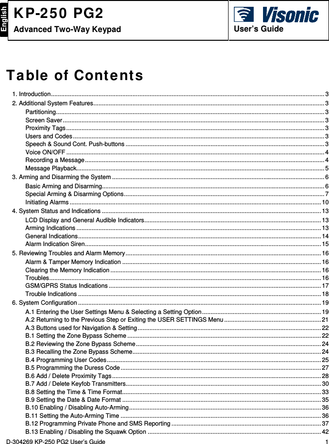
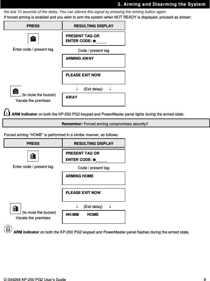
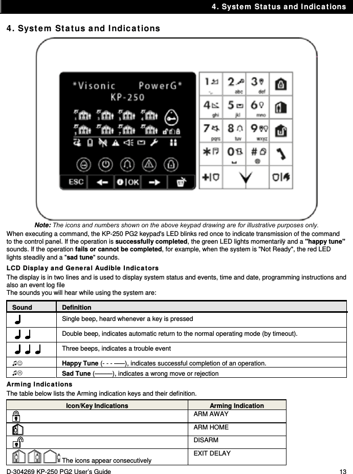
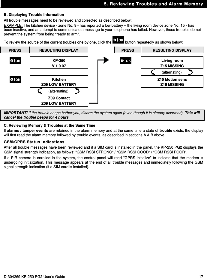
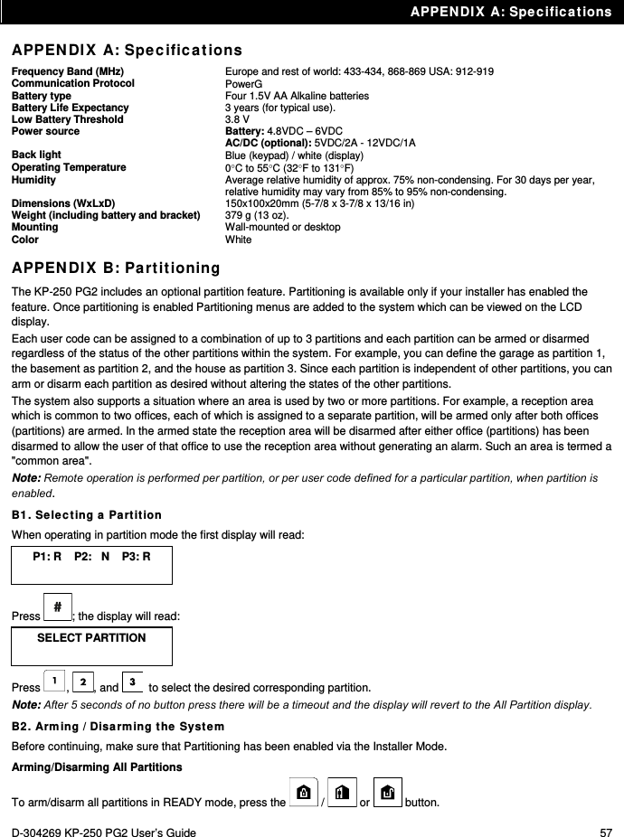
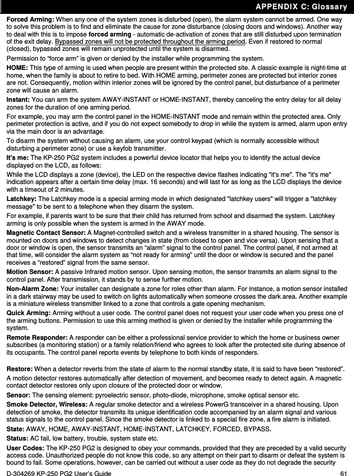
![6. System Configuration D-304269 KP-250 PG2 User’s Guide 19 6. System Configuration This chapter explains the user programming features of your PowerMaster system using the KP-250 PG2 keypad. To access the User Settings menus, a KP-250 PG2 keypad must first be enrolled in the system. For instructions on how to enroll the KP-250 PG2 Keypad, refer to the KP-250 PG2 Installer’s Guide, section 11.4. The Master User has access to all the User Settings menus, while the User has access only to the bypass menus (see section B.4 in this chapter, which describes in detail the concept of User and Master User codes). A.1 Entering the User Settings Menu & Selecting a Setting Option The following procedure describes how to enter and move within the User Settings menu. Detailed descriptions of the User Settings options are provided at the end of the procedure. To exit the User Settings menu – see section A.2. 1. You can enter the "USER SETTINGS" menu only when the system is disarmed. 2. Carefully read the section titled "Additional Information" according to the indicated references 1 etc – see table at end of this section. A. To Enter the USER SETTINGS Menu 1. HH:MM READY Make sure the system is disarmed and then press the button repeatedly on the KP-250 PG2 until the display reads [USER SETTINGS]. 1 2. USER SETTINGS Press PRESENT TAG OR ENTER CODE: The screen will now prompt you to enter your user code or present your proximity tag. 3. CODE Enter your User Code. 2 SET ZONE BYPASS The display reads the first Setting option of the User Settings menu [SET ZONE BYPASS]. 3 B. To Select a Setting Option 4. SET ZONE BYPASS Click the or button until the display reads the desired setting option, for example, "TIME & FORMAT". or 5. TIME & FORMAT When the desired setting option appears on the display, press the button to enter the setting process. Continue to the selected setting option in B.1 - B.16 The remainder of the procedures for the selected setting options is provided in sections B.1 to B.16. Additional Information (section A.1) 1 Display shown in disarm state when all zones are secured (00:00 or other digits show present time).](https://usermanual.wiki/Visonic/KP250PG2/User-Guide-2406625-Page-19.png)
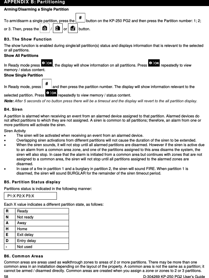
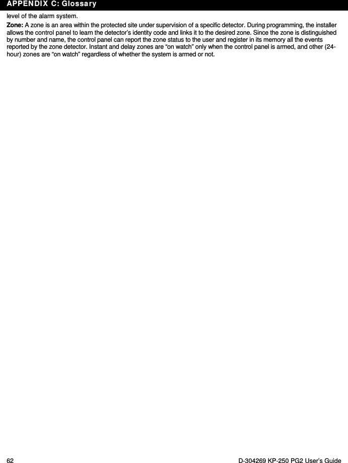
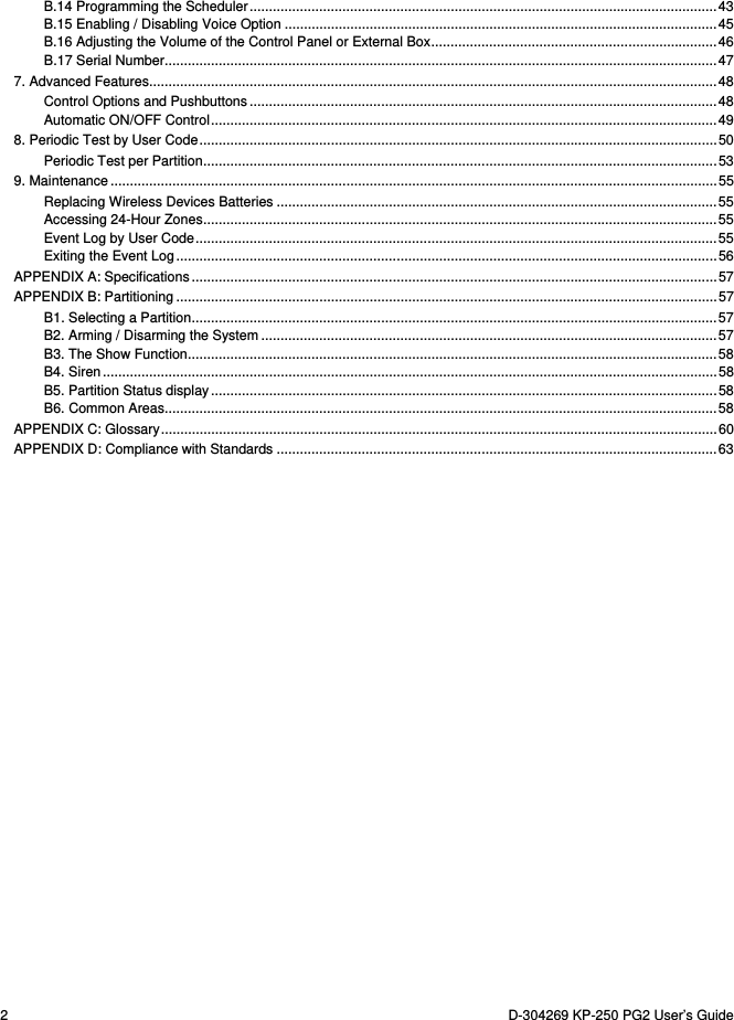
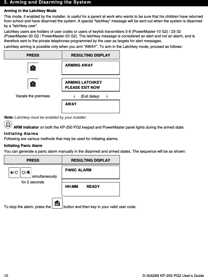
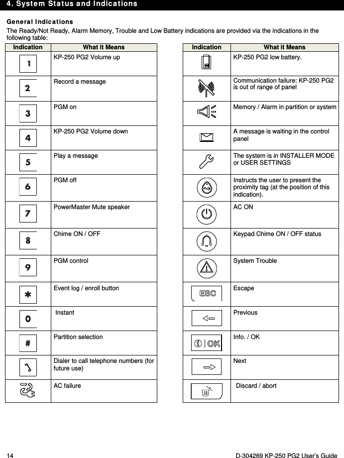
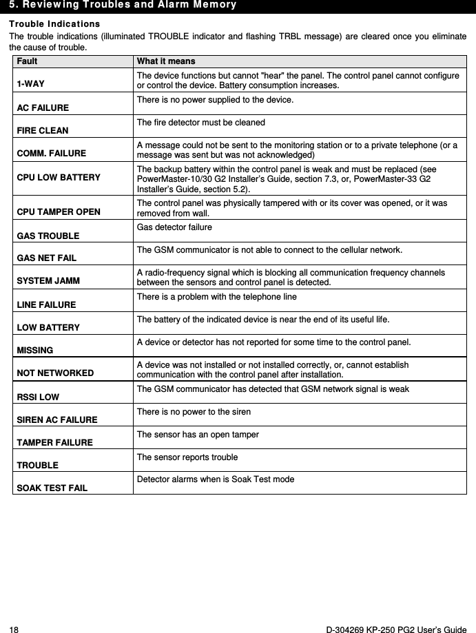
![6. System Configuration 20 D-304269 KP-250 PG2 User’s Guide C. User Settings Options Menu Click until the display reads the desired setting option and then press . SET ZONE BYPASS Use to set the Zone Bypass Scheme i.e. to bypass (exclude) faulty or unsecured ("disturbed") zones, or to clear a bypassed zone (unbypass). For further details and programming procedure see section B.1. REVIEW BYPASS Use to quickly review the Bypass Scheme i.e. which zones are bypassed. For further details and reviewing procedure see section B.2. RECALL BYPASS Use to Recall the last used bypassed scheme for reuse in next arming period. For further details and recalling procedure see section B.3. USER CODES Use to program your Master User secret access code and the seven codes of the other users. For further details and programming procedure see section B.4. DURESS ALARM CODE 2580 Use to send a duress (ambush) alarm message to the Monitoring Station if you are forced to disarm the system under violence or menace. For further details and programming procedure see section B.5. PROXIMITY TAGS Use to add new Proximity Tags to or to delete Proximity Tags when lost. For further details and programming procedure see section B.6. KEYFOBS Use to add new Keyfob Transmitters or to delete Keyfob Transmitters when lost. For further details and programming procedure see section B.7. TIME & FORMAT Use to set the time clock to show the correct time and time format. For further details and programming procedure see section B.8. DATE & FORMAT Use to set the calendar date to show the correct date and date format. For further details and programming procedure see section B.9. AUTO-ARM disable Use to enable or disable the Automatic Daily Arming option at predefined times (see Auto-Arm Time setting). For further details and programming procedure see section B.10. 2 a. If you have not already changed your personal code number, use the default setting – 1111. b. Master User has access to all User Settings options. Other users have access only to the Bypass options. c. If you enter an invalid user code 5 times, the keypad will be automatically disabled for a pre-defined period of time and the message WRONG PASSWORD will be displayed. 3 The bypass options will be displayed in the User Settings menu only if enabled by the installer. Otherwise, the first User Settings option displayed will be [USER CODES].](https://usermanual.wiki/Visonic/KP250PG2/User-Guide-2406625-Page-20.png)
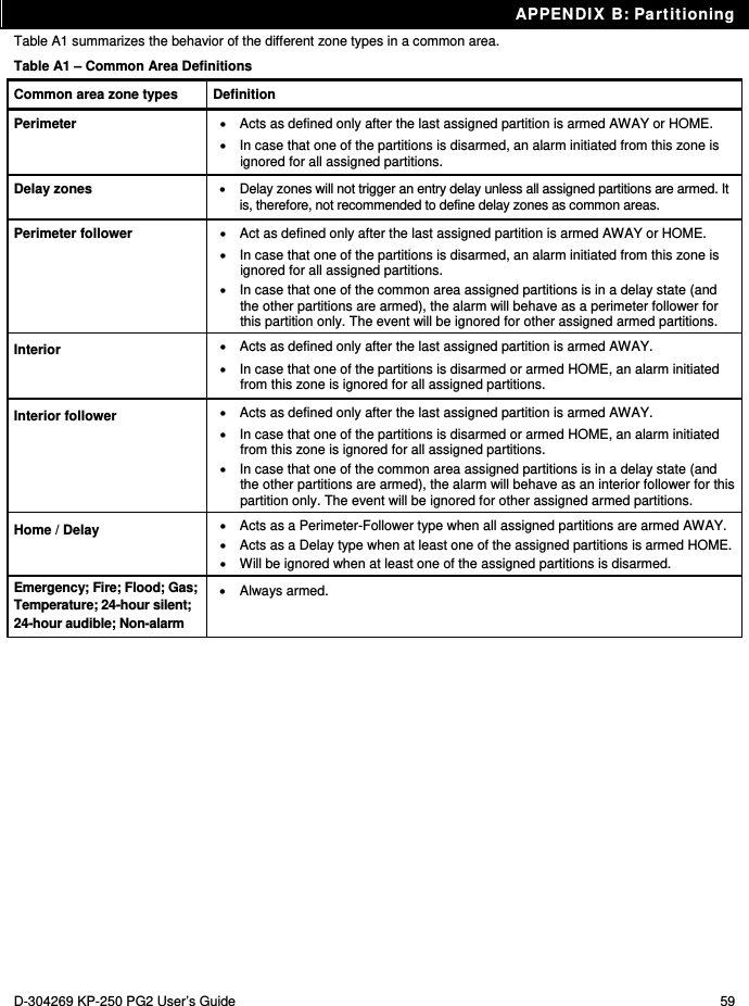
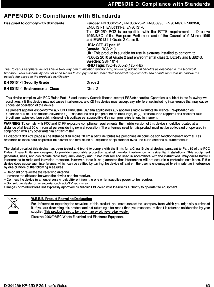
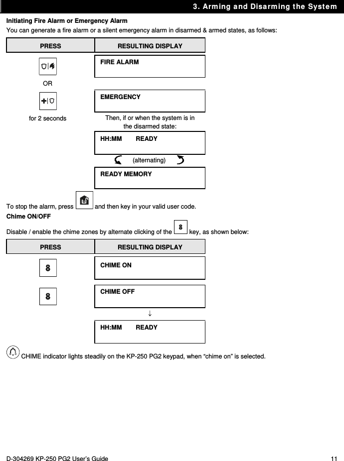
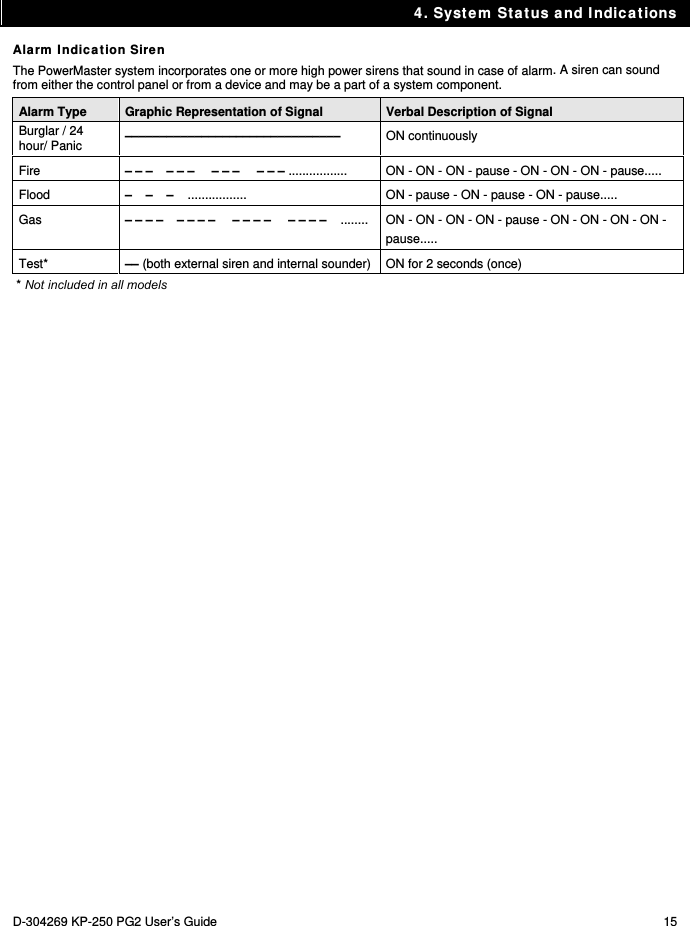
![6. System Configuration D-304269 KP-250 PG2 User’s Guide 21 AUTO-ARM TIME 12:00P Use to set the predetermined time for the Automatic Daily Arming if enabled (see Auto-Arm Enable setting). For further details and programming procedure see section B.11. PRIVATE REPORT Use to program the four private telephone numbers for reporting alarm and other event messages to private subscribers. For further details and programming procedure see section B.12. SQUAWK on Use to enable or disable the squawk sound i.e. arm / disarm feedback indication. For further details and programming procedure see section B.13. SCHEDULER Use to set the daily / weekly time schedule for start & stop activation of devices connected to the PGM output. For further details and programming procedure see section B.14. VOICE OPTION disable Use to enable or disable the voice option i.e. the voice prompts that are heard over the external voice box. For further details and programming procedure see section B.15. PANEL VOLUME Use to adjust the volume of the panel’s speaker or external voice box. For further details and programming procedure see section B.16. SERIAL NUMBER Use to read the system serial number and similar data. For further details see section B.17. <OK> TO EXIT Use to exit from the “USER SETTINGS” menu back to Main Menu. For further details see section A.2. Returns to first option A.2 Returning to the Previous Step or Exiting the USER SETTINGS Menu During the setting process it is frequently necessary to return to the previous setting step or option (i.e. "to go one level up") or to exit the User Settings menu. 1. To Move One Level Up To move one level up during the setting process, click once or more. Each click will take you one level up or to the previous setting step. 2. To Exit the USER SETTINGS Menu 1. Any screen To exit [USER SETTINGS], move up the menu by pressing repeatedly (see above) until the display reads [<OK> TO EXIT], or preferably, press once which brings you immediately to the exit screen [<OK> TO EXIT]. 2. or <OK> TO EXIT When the display reads [<OK> TO EXIT], press 3.](https://usermanual.wiki/Visonic/KP250PG2/User-Guide-2406625-Page-21.png)
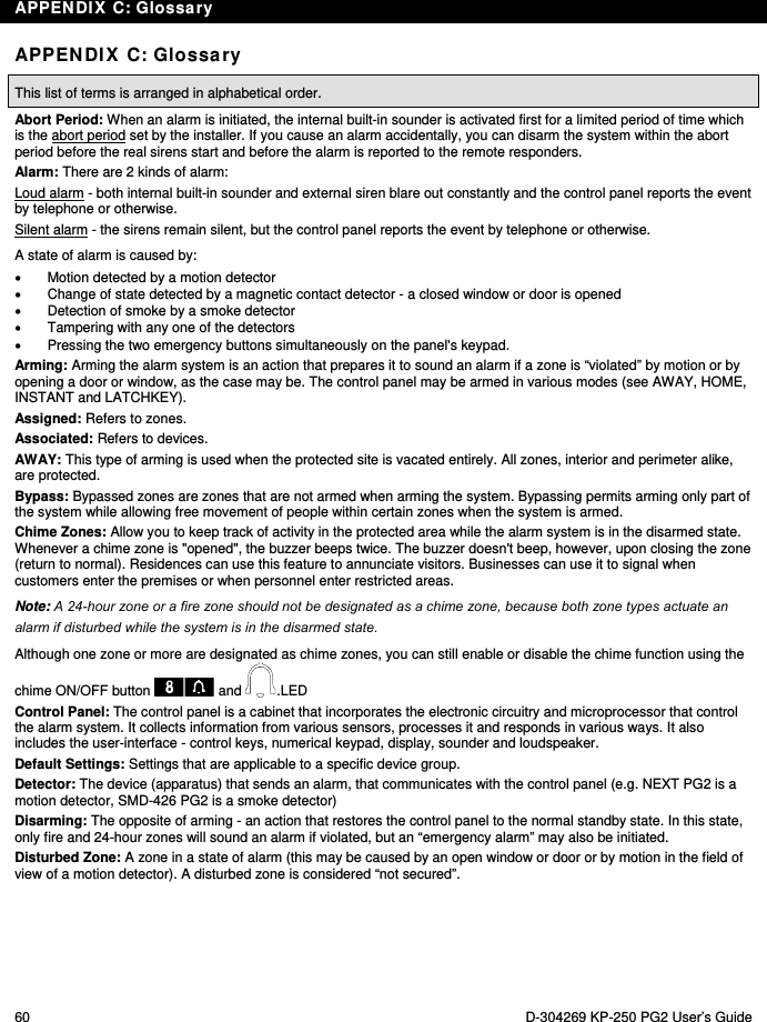
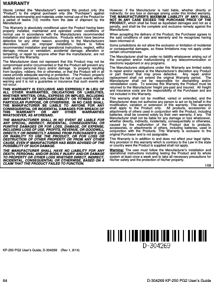
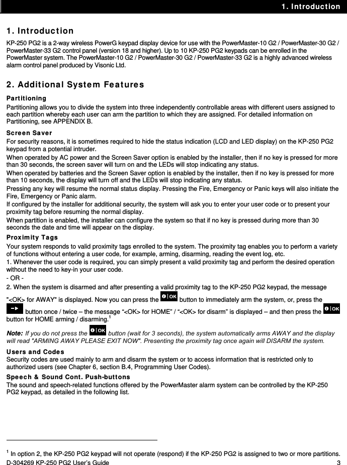
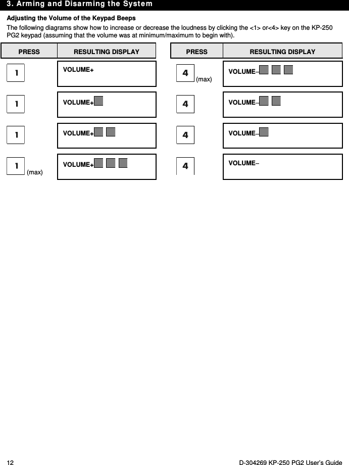
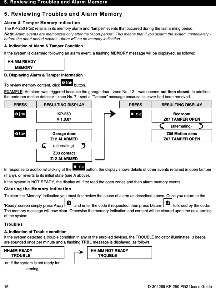
![6. System Configuration 22 D-304269 KP-250 PG2 User’s Guide 12:00 READY The system exits the [USER SETTINGS] menu and returns to the normal disarm state while showing the READY display. A.3 Buttons used for Navigation & Setting The keypad's buttons are used for various functions when programming. The following table provides a detailed description of the function or use of each button. Button Definition Navigation / Setting Function NEXT Use to move / scroll forward to the next menu options. BACK Use to move / scroll backward to the previous menu options. OK Use to select a menu option or to confirm a setting or action. Escape Use to move one level up in the menu or to return to previous setting step. Delete / abort Use to edit a field or jump back to the [<OK> TO EXIT] screen to quit programming. - Numerical keypad used to enter numerical data. Partition selection Use to change the status of partitions when programming user codes B.1 Setting the Zone Bypass Scheme Bypassing permits arming only part of the system and at the same time allowing free movement of people within certain zones when the system is armed. It is also used to temporarily remove from service faulty zones that require repair work or to deactivate a sensor if, for example, you are decorating a room. Here you can set the Zone Bypass Scheme i.e. to scroll through the list of registered (enrolled) sensors to your PowerMaster system and to Bypass (deactivate) faulty or disturbed sensors (either READY or NOT-READY) or to Clear (reactivate) BYPASSED zones (sensors). Once you have set a Bypass Scheme you can use the following 3 options: > To quickly review the bypassed zones – refer to section B.2. > To quickly clear a bypassed zone i.e. to reactivate the bypassed zone – refer to section B.1. > To repeat (recall) the last used zone bypassing scheme – refer to section B.3. 1. Zones will be bypassed throughout one disarm-arm period only. Disarming the system after arming will suspend the entire bypassing scheme but you can recall and reuse it as described in section B.3. 2. Fire zones cannot be bypassed. 3. Carefully read the section titled "Additional Information" according to the indicated references 1 etc – see table at end of section B.3. REMEMBER – ZONE BYPASSING COMPROMISES SECURITY!](https://usermanual.wiki/Visonic/KP250PG2/User-Guide-2406625-Page-22.png)
![6. System Configuration D-304269 KP-250 PG2 User’s Guide 23 A. To Bypass a Zone 1. SET ZONE BYPASS Enter the [USER SETTINGS] menu1, select the [SET ZONE BYPASS] 2 option and press . Z01: READY Living Room The first zone, Z01, is displayed. 3 Z01: P1 P2 P3 4 2. or Click the or button until the display reads the zone you wish to bypass (or clear bypass), for example, "Z04" for Zone 04. After several seconds the LEDs on the respective device starts flashing indicating "it's me". Z04: NOT READY Z04: P1 P2 P3 3. Kitchen When the display reads the zone you wish to bypass press . 4. <OK> TO BYPASS The display now reads [<OK> TO BYPASS]. 5 To bypass the selected zone press Z04:BYPASSED A "Happy Tune" ☺ sounds and the updated zone status is now displayed i.e. [Z04: BYPASSED]. 8 B. To Clear a Bypassed Zone 5. Z04: BYPASSED Z04: P1 P2 P3 Repeat steps 1 to 2 above. 4 6. Kitchen When the zone you wish to clear bypass appears on the display (for example, "Z04"), press to confirm. You can also identify the device by looking for the "it's me" LED indication on the displayed device. <OFF> TO CLEAR The display now reads [<OFF> TO CLEAR]. 5 7. To clear the bypassed zone, press the button. Z04:READY A "Happy Tune" ☺ sounds and the updated zone status is now displayed, i.e. [Z04: READY] or [Z04: NOT READY]. 9](https://usermanual.wiki/Visonic/KP250PG2/User-Guide-2406625-Page-23.png)
![6. System Configuration 24 D-304269 KP-250 PG2 User’s Guide B.2 Reviewing the Zone Bypass Scheme Here you can quickly review the Bypass Scheme i.e. the zones that are set to be bypassed during the next arming session. 1. REVIEW BYPASS Enter the [USER SETTINGS] menu and select the [REVIEW BYPASS]1 option and press . 2 2. BYPASS LIST The display reads [BYPASS LIST] or Click the or buttons repeatedly to review all bypassed zones in ascending numerical order. When done, click to exit. 9 3. Z04: BYPASSED Z04: P1 P2 P3 Kitchen B.3 Recalling the Zone Bypass Scheme Use this option to repeat (recall) the most recent Bypassed Scheme for use during the next arming session. 1. RECALL BYPASS Enter the [USER SETTINGS] menu, select the [RECALL BYPASS] 1 option and press . 2, 6 2. <OK> TO RECALL The display now reads [<OK> TO RECALL]. 7 To recall the last used bypass scheme press . BYPASS RECALLED A "Happy Tune" ☺ sounds. The display reads [BYPASS RECALLED] and then returns to “USER SETTINGS" step 1. 9 ☺ Return to step 1 Additional Information (section B.1 – B.3) 1 For detailed instructions on how to select User Settings – refer to section A.1 and section A.2. 2 This menu is displayed only if "BYPASS" was previously enabled by the installer. 3 The STATUS to the right of the zone number indicates whether the zone is READY, NOT-READY or BYPASSED. 4 This display will appear only if PARTITIONING was previously enabled.](https://usermanual.wiki/Visonic/KP250PG2/User-Guide-2406625-Page-24.png)
![6. System Configuration D-304269 KP-250 PG2 User’s Guide 25 5 a. If the zone you selected is "not bypassed", the display prompts you to press [<OK> TO BYPASS]. However, if the zone you selected is already "bypassed", the display prompts you to press [<OFF> TO CLEAR]. b. To abort and return to the previous step press or 6 This menu is not displayed if Partition is enabled. 7 The display now prompts you to press [<OK> TO RECALL] i.e. to repeat the last used bypass scheme. To abort and return to the User Settings menu, press . 8 You can now repeat steps 2 - 4 to bypass or clear another zone. To end this session and to select other menu options or to quit programming - follow the instructions in section A.2. 9 You can now select another option in the User Settings menu (see section A.1), or quit programming (see section A.2). B.4 Programming User Codes PowerMaster system allows you to authorize up to 8 (PowerMaster-10 G2) / 48 (PowerMaster-30 G2 / PowerMaster-33 G2) people to arm and disarm the system by providing each with a unique 4 digit personal security code (code 0000 is not allowed), and assigning them with different security levels and functionalities. Moreover, you can obtain up to 8 (PowerMaster-10 G2) / 32 (PowerMaster-30 G2 / PowerMaster-33 G2) multi-function portable keyfob transmitters that will allow you and the other users to easily arm, disarm and control the system without accessing the KP-250 PG2 or panel, including from outside the premises (see section B.7 Add / Delete Keyfob Transmitters). The Duress Code enables you to disarm the system using a special code that sends a silent alarm to the monitoring station. There are two types of users: Master User and User. The table below summarizes the different operations that can be performed by different users: User type Function Master User Arm/disarm Zone bypass Authorize other user codes Set user codes Report to private Enroll/delete proximity tag Enroll/delete keyfob Automatic arming Enable squawk Set date and time format Read event log Programming the duress code Programming the scheduler Enabling/disabling voice option Adjusting volume User Arm/disarm Zone bypass options The user codes are assigned as follows: User Code 1 is assigned to the Master User of the system (i.e. the owner). It is the only user code that allows access to the User Settings menu. The default setting of the Master User code is 1111. This code cannot be erased and must be replaced with a secret code as soon as possible. User Codes 2-4 (PowerMaster-10 G2) / User Codes 2-22 and 33-48 (PowerMaster-30 G2 / PowerMaster-33 G2) are assigned to family members, co-workers etc. They enable arming and disarming of the system or of selected partitions as defined by the Master User. They can access the "User Settings" menu only for "zone bypassing" provided this option is enabled in the Installer menu.](https://usermanual.wiki/Visonic/KP250PG2/User-Guide-2406625-Page-25.png)
![6. System Configuration 26 D-304269 KP-250 PG2 User’s Guide User Codes 5-8 (PowerMaster-10 G2) / User Codes 23-32 (PowerMaster-30 G2 / PowerMaster-33 G2) are the same as user codes 2-4 (PowerMaster-10 G2) / 2-22 (PowerMaster-30 G2 / PowerMaster-33 G2) but can be assigned to "Latchkey" (child monitor) users. For a detailed explanation of the Latchkey application see Chapter 3. A. To Program a User Code Partition Option (For information about Partition option - see APPENDIX B) Your alarm system can divide zones into up to 3 parts (groups) via the installer menu. These parts are designated as partitions P1, P2 & P3. Each partition can be armed and disarmed separately, providing protection to selected parts of the premises. Each user out of the 8 (PowerMaster-10 G2) / 48 (PowerMaster-30 G2 / PowerMaster-33 G2) system users can be authorized by the Master User to arm and disarm any combination of partitions including all 3 partitions. Here you can program (or edit) the 8 (PowerMaster-10 G2) / 48 (PowerMaster-30 G2 / PowerMaster-33 G2) User Codes and thereby define which of these will be authorized to arm and disarm. 1. The default setting 1111 of the Master User Code is the same for all PowerMaster systems and is known to many other people. Therefore, we highly recommend that you immediately replace it with a unique secret code. 2. Code "0000" is not valid! Do not use it. 3. The duress code (2580 by default), which is set in the installer menu, cannot be selected as a normal user code. Any attempt to program it will be rejected by the system. 4. Carefully read the section titled "Additional Information" according to the indicated references 1 etc – see table at end of this section. 1. USER CODES Enter the [USER SETTINGS] menu, select the [USER CODES] option and press . 1 2. User 01: 1111 The first user code "User 01: 1111" is displayed. 2 or At the blinking cursor position, key in the User Code you wish to program , for example, [06] for user code 6, or alternatively click the or button until the display reads, [User 06: 0000]. 3. User 06: 0000 When the user code you wish to program appears on the display, press . 4. User 06: 0000 To program or edit the code, at the blinking cursor position enter the 4 digit code, for example, “1234”, using the numerical keypad. 3, 4 5. When done, press . User 06: 1234 ☺ Return to step 3 A "Happy Tune" ☺ sounds. The display confirms the saved code. 5, 6](https://usermanual.wiki/Visonic/KP250PG2/User-Guide-2406625-Page-26.png)
![6. System Configuration 28 D-304269 KP-250 PG2 User’s Guide 1. DURESS CODE 2580 Enter the [USER SETTINGS] menu, select the [DURESS CODE] option and press . 1 2. DURESS CODE 2580 At the blinking cursor position, key in the Duress Code you wish to program, for example, 6973. 2, 3 DURESS CODE 6973 When the duress code you wish to program appears on the display, press . 3. ☺ Return to step 1 A "Happy Tune" ☺ sounds and The display confirms the saved setting. 4 Additional Information (section B.5) 1 For detailed instructions on how to select User Settings – refer to section A.1 and section A.2. 2 The display shows the default duress code (2580). 3 Do not set the duress code the same as an installer or user code. 4 You can now select another option in the User Settings menu or quit programming (see sections A.1 and A.2). B.6 Add / Delete Proximity Tags Users of the alarm system may be provided with a proximity tag/s that can be used instead of the user codes to perform a variety of functions, for example, arming, disarming, reading the event log, etc. Whenever a user code is required you can simply present a valid proximity tag instead of entering the user code. Here you can add (enroll) new proximity tags or delete tags as required. Carefully read the section titled "Additional Information" according to the indicated references1 etc – see table at end of this section. A. To Add (Enroll) a Proximity Tag 1. TAGS (Proximity) Enter the [USER SETTINGS] menu, select the [TAGS (Proximity)] option and press . 1 2. ADD NEW TAG The display will read [ADD NEW TAG]. 3 To begin the process of enrolling a new proximity tag press . 3. ENROLL NOW or ENTR ID:xxx-xxxx Present the proximity tag to the KP-250 PG2 within the timeout period. 4. DEVICE ENROLLED T01:Tag (Prox) If enrollment was successfully completed, a "Happy Tune" ☺ sounds and the display reads [DEVICE ENROLLED] for a short duration and then changes to read](https://usermanual.wiki/Visonic/KP250PG2/User-Guide-2406625-Page-28.png)
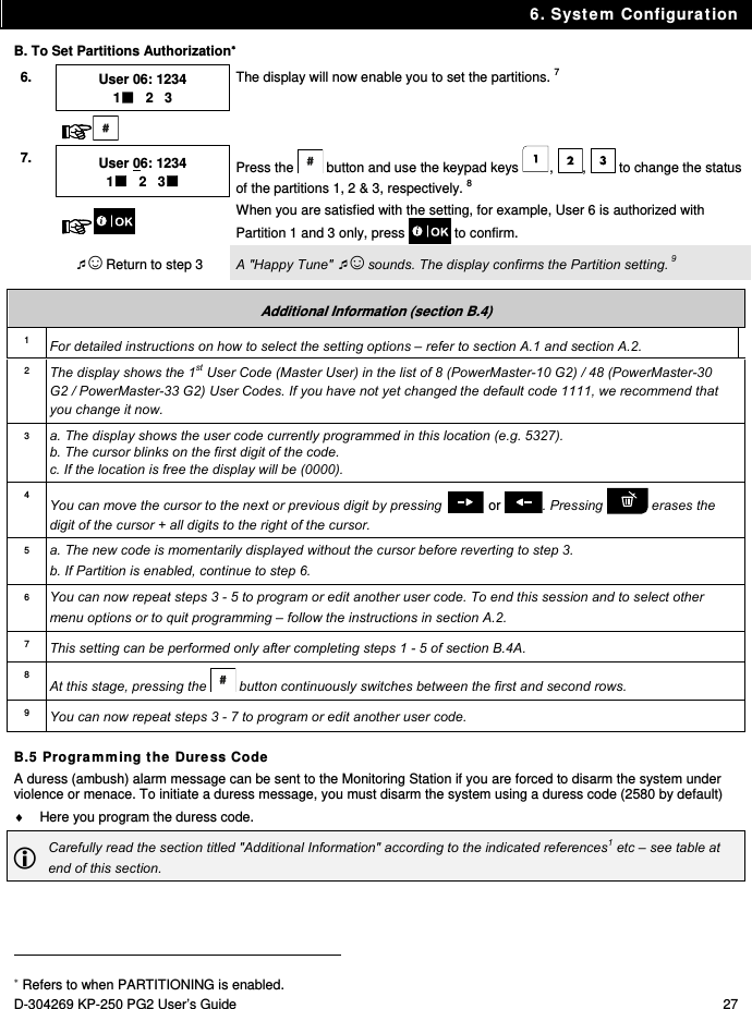
![6. System Configuration D-304269 KP-250 PG2 User’s Guide 29 ☺ Go to step 5 the tag's details. 4 The display shows the allocated tag serial No (user No.), which is always the first free number, for example: [T01:Tag (Prox)]. 5. or To assign the tag to another user, for example, "User No. 5", key in [05] or alternatively click the or button until the display reads [T05:Tag (Prox)] and then press to confirm. DEVICE ENROLLED T05:Tag (Prox) ☺ Return to step 2 The display reads [DEVICE ENROLLED] a "Happy Tune" ☺ sounds and the display will then change to [T01:Tag (Prox)]. 5 6 B. To Set Partitions Authorization C. To Delete a Proximity Tag 1. TAGS (Proximity) Enter the [USER SETTINGS] menu, select the [TAGS (Proximity)] option and press . 1 2. ADD NEW TAG The display will read [ADD NEW TAG]. Click the button until the display reads [DELETE TAG]. 3. DELETE TAG Press . T01:Tag (Prox) The display will read [T01:Tag (prox)]. 2, 7 4. Key in the tag number you wish to delete, for example, [05] or alternatively click the or button until the display reads the tag number, [T05:Tag (prox)]. 5. When the tag you wish to delete appears on the display, press . <DEL> to delete The display now reads [<DEL> to delete]. 8 Refers to when PARTITIONING is enabled. 6. T05:PARTITIONS 1 2 3 Use the keypad keys , , to change the status of the partitions 1, 2 & 3, respectively. 9 7. T05:PARTITIONS 1 2 3 When you are satisfied with the setting, for example, User 5 is authorized with Partition 1 and 3 only, press to confirm. ☺ Return to step 2 A "Happy Tune" ☺ sounds. The display confirms the Partition setting. 10](https://usermanual.wiki/Visonic/KP250PG2/User-Guide-2406625-Page-29.png)
![6. System Configuration 30 D-304269 KP-250 PG2 User’s Guide 6. To delete the tag press the button. DELETE TAG A "Happy Tune" ☺ sounds and the display reads [DELETE TAG] and returns to step 3. 11 ☺ Go to step 3 Additional Information (section B.6) 1 For detailed instructions on how to select User Settings – refer to section A.1 and section A.2. 2 The display shows the first enrolled Tag (Tag No.1) of the 8 (PowerMaster-10 G2) / 32 (PowerMaster-30 G2 / PowerMaster-33 G2) tags. 3 To abort enrollment, press the button. 4 If the tag was previously enrolled in the system, the KP-250 PG2 display indicates this together with the tag's ID number, for example, "ALREADY ENROLLED T01:Tag (Prox)". 5 If Partition is enabled, continue to step 6. 6 You can now enroll another proximity tag. You can also select another option in the User Settings menu (see section A.1 and section A.2), or quit programming (see section A.3). 7 If no proximity tag is enrolled in the system, the display reads [NO EXISTING DEV.]. 8 To abort the procedure, press the button. 9 This setting can be performed only after completing steps 1 - 5 of section B.6A. 10 You can now repeat steps 2 - 7 to program or edit another Proximity tag. 11 You can now add or delete another proximity tag. You can also select another option in the User Settings menu (see section A.1 and section A.2), or quit programming (see section A.3). B.7 Add / Delete Keyfob Transmitters Each of the 8 (PowerMaster-10 G2) / 32 (PowerMaster-30 G2 / PowerMaster-33 G2) users may be provided with a portable keyfob transmitter for better, quicker and safer arming/disarming and other control functions. Each keyfob should be assigned with a serial No. 1-8 (PowerMaster-10 G2) / 1-32 (PowerMaster-30 G2 / PowerMaster-33 G2) and enrolled into the system correspondingly. Partition Option (For information about Partition option - see APPENDIX B). If the Partition option is enabled in the KP-250 PG2, each of the 8 (PowerMaster-10 G2) / 32 (PowerMaster-30 G2 / PowerMaster-33 G2) keyfobs can be authorized by the Master User to arm and disarm any combination, or all 3 partitions, irrespective of the authorization of its corresponding user code. Here you can add (enroll) the 8 (PowerMaster-10 G2) / 32 (PowerMaster-30 G2 / PowerMaster-33 G2) Keyfob transmitters and define which of the 3 partitions each of the keyfob will be authorized to arm and disarm, or delete keyfobs as required. 1. Before anything else, gather up all keyfob units you intend to enroll and make sure they all have batteries installed and that they are active (the LED blinks upon pressing any of the buttons). 2. Carefully read the section titled "Additional Information" according to the indicated references1 etc – see table at end of this section.](https://usermanual.wiki/Visonic/KP250PG2/User-Guide-2406625-Page-30.png)
![6. System Configuration D-304269 KP-250 PG2 User’s Guide 31 A. To Add (Enroll) a Keyfob 1. KEYFOBS Enter the [USER SETTINGS] menu, select the [KEYFOBS] option and press . 1 2. ADD NEW KEYFOB The display will read [ADD NEW KEYFOB]. 4 To enroll a new keyfob press . 3. ENROLL NOW or ENTR ID:xxx-xxxx The display offers you two alternative methods to enroll a keyfob: A: ENROLL NOW: Press and hold the AUX button on the selected keyfob until the LED is constantly on. 2 This procedure completes the enrollment. 4a. DEVICE ENROLLED ID No. 300-5786 If enrollment was successfully completed, a "Happy Tune" ☺ sounds and the display reads [DEVICE ENROLLED] for a short duration and then changes to read the keyfob's details. Continue to step 5. DEVICE ENROLLED F01:KEYFOB ☺ Go to step 5 4b. ID No. 300-5786 B: ENROLLMENT BY DEVICE ID: Enter the 7-digit number that appears on the keyfob sticker and then press to confirm. To complete the enrollment procedure, see Note 9 in the Additional Information table below. ID ACCEPTED If a valid ID was entered, a "Happy Tune" ☺ sounds and the display reads [ID ACCEPTED] for a short duration and then changes to read the keyfob's details. Continue to step 5. ☺ Go to step 5 5. F01:keyfob ID No. 300-5786 The display shows the allocated keyfob serial No (user No.), which is always the first free number, and the keyfob's ID number; for example: [F01:Keyfob] alternating with [ID No. 300-5786]. or To assign the keyfob to another user, for example, "User No. 5", key in [05] or alternatively click the or button until the display reads [F05:Keyfob] and then press to confirm. F05:keyfob ☺ Return to step 2 The display reads [DEVICE ENROLLED] or [ID accepted] if the keyfob was enrolled manually by entering the ID number, a "Happy Tune" ☺ sounds and the display will then change to [F01:Keyfob]. 5 6](https://usermanual.wiki/Visonic/KP250PG2/User-Guide-2406625-Page-31.png)
![6. System Configuration 32 D-304269 KP-250 PG2 User’s Guide B. To Set Partitions Authorization 6. F05:PARTITIONS Press to enter partitions mode. 7. F05:PARTITIONS 1 2 3 Use the keypad keys , , to change the status of the partitions 1, 2 & 3, respectively. 10 8. F05:PARTITIONS 1 2 3 When you are satisfied with the setting, for example, User 5 is authorized with Partition 2 and 3 only, press to confirm. 11 ☺ Return to step 2 A "Happy Tune" ☺ sounds. The display confirms the Partition setting. 12 C. To Delete a Keyfob 1. KEYFOBS Enter the [USER SETTINGS] menu, select the [KEYFOBS] option and press . 1 2. ADD NEW KEYFOB The display will read [ADD NEW KEYFOB]. Click the button until the display reads [DELETE KEYFOB]. 3. DELETE KEYFOB Press . F01:Keyfob ID No. 300-5786 The display will read [F01:Keyfob] and the ID number of the keyfob. 3 4. or Key in the keyfob number you wish to delete, for example, [06] or alternatively click the or button until the display reads the keyfob number, for example, "F06:Keyfob" and "ID No. 300-5799". F06:Keyfob ID No. 300-5799 When the keyfob you wish to delete appears on the display, press . 7 5. <DEL> to Delete The display now reads [<DEL> to Delete]. 8 6. To delete the keyfob press the button. 13 Refers to when PARTITIONING is enabled.](https://usermanual.wiki/Visonic/KP250PG2/User-Guide-2406625-Page-32.png)
![6. System Configuration D-304269 KP-250 PG2 User’s Guide 33 ☺ Go to step 3 DELETE KEYFOB A "Happy Tune" ☺ sounds and the display reads [DELETE KEYFOB] and returns to step 3. 14 Additional Information (section B.7) 1 For detailed instructions on how to select User Settings – refer to section A.1 and section A.2. 2 The LED will extinguish after several seconds. In case of difficulties in communication with the control panel, the LED may blink for several seconds more while trying to establish communication. During this period of time the keyfob keys are disabled. 3 The display shows the first enrolled Keyfob (Keyfob No.1) of the 8 (PowerMaster-10) / 32 (PowerMaster-30 G2 / PowerMaster-33 G2) keyfobs. 4 To abort enrollment, press the button. 5 If Partition is enabled, continue to step 6. 6 You can now enroll another keyfob. You can also select another option in the User Settings menu (see section A.1 and section A.2), or quit programming (see section A.3). 7 If the keyfob was previously enrolled in the system, the KP-250 PG2 display indicates this together with the keyfob's ID number, for example, "ALREADY ENROLLED F01:KEYFOBS". 8 Before you delete a keyfob, identify the keyfob either by the keyfob No., for example, F06, or by the ID number of the keyfob that appears on the display, and then make sure that it is the keyfob you wish to delete. 9 Enrollment by Device ID: Step 4b enables you to register the device ID and to complete the programming process without being in possession of the device itself (can also be performed off-site by the installer). Enrollment can then be completed at a later stage by following the same enrollment procedure described in Step 3 without entering the User Settings menu. 10 This setting can be performed only after completing steps 1 - 5 of section B.7A. 11 The box symbol now appears next to the newly selected Partitions. 12 You can now repeat steps 2 - 8 to program or edit another keyfob. 13 To abort the procedure, press the button. 14 You can now add or delete another keyfob or select another option in the User Settings menu or quit programming (see sections A.1 and section A.2). B.8 Setting the Time & Time Format Here you can program or adjust the built-in-clock to show the correct time in the desired time format. You can select between a 24 hour and a 12 hour (AM/PM) time format. Carefully read the section titled "Additional Information" according to the indicated references1 etc – see table at end of this section.](https://usermanual.wiki/Visonic/KP250PG2/User-Guide-2406625-Page-33.png)
![6. System Configuration 34 D-304269 KP-250 PG2 User’s Guide A. To Set the Time Format 1. TIME & FORMAT Enter the [USER SETTINGS] menu and select the [TIME & FORMAT] option and press . 1 2. EU FORMAT 24H TIME: 19:22 The display shows the currently selected time format. 2 or Click the or button until the display shows the desired time format, for example, "US FORMAT-24H" and press to confirm . US FORMAT-12H TIME: 03:15P 3. B. To Set the Time 5 4. US FORMAT-12H TIME: 03:15P At the blinking cursor position, enter the correct time, for example, “8:55A”, using the numerical keypad. 3 4 5. When you are satisfied with the setting, press to confirm. US FORMAT-12H TIME: 08:55A A "Happy Tune" ☺ sounds, the display reads the set time, returns to step 1. 6, 7 ☺ Return to step 1 Additional Information (section B.8) 1 For detailed instructions on how to select User Settings – refer to section A.1 and section A.2. 2 a. The display shows the currently selected format, for example, "24 Hrs". b. You can now select either the 12 Hrs or 24 Hrs time format using the or buttons. 3 The display shows the Time in the selected Time Format, for example, "12:40 PM", with the cursor blinking on the first hour digit "1". The letter that follows the displayed time indicates one of the following: "A" = AM; "P" = PM and "none" for 24 Hrs time format. When the curser is positioned on the AM/PM digit, you can set to "AM" with the button and the "PM" with the button. 4 You can move the cursor to the next or previous digit using the or buttons. 5 This setting can be performed only after completing steps 1 – 3 of section B.8A. 6 The time saved is displayed without the cursor, for example, "08:55 A" followed by the selected time format. 7 You can now select another option in the User Settings menu (see section A.1 and section A.2), or quit programming (see section A.3).](https://usermanual.wiki/Visonic/KP250PG2/User-Guide-2406625-Page-34.png)
![6. System Configuration D-304269 KP-250 PG2 User’s Guide 35 B.9 Setting the Date & Date Format Here you can program or adjust the built-in-calendar to show the correct date in the desired date format. You can select between a "mm/dd/yyyy" and a "dd/mm/yyyy" date format. Carefully read the section titled "Additional Information" according to the indicated references1 etc – see table at end of this section. A. To Set the Date Format 1. DATE & FORMAT Enter the [USER SETTINGS] menu and select the [DATE & FORMAT] option and press . 1 DATE DD/MM/YYYY DATE: 01/01/2012 The display shows the currently selected date format. 2 2. or Click the or button until the display reads the desired date format, for example, "DD/MM/YYYY" and press to confirm. DATE DD/MM/YYYY DATE: 01/01/2012 3. B. To Set the Date 7 4. DATE DD/MM/YYYY DATE: 20/04/2012 At the blinking cursor position, enter the correct date, for example, “20/04/2012”, using the numerical keypad. 3, 4, 5 5. When you are satisfied with the setting, press to confirm. DATE DD/MM/YYYY DATE: 20/04/2012 A "Happy Tune" ☺ sounds, the display shows the set date and returns to step 1. 6 ☺ Return to step 1 Additional Information (section B.9) 1 For detailed instructions on how to select User Settings – refer to section A.1 and section A.2. 2 The display shows the currently selected format, for example, "DD/MM/YYYY". You can now select either the "MM/DD/YYYY" or "DD/MM/YYYY" date format by pressing or . 3 The display shows the Date and selected Date Format, for example, "30.12.2012", with the cursor blinking on the first digit. 4 You can move the cursor to the next or previous digit using the or button. 5 For the year, enter the two last digits only. 6 You can now select another option in the User Settings menu (see section A.1 and section A.2), or quit programming (see section A.3). 7 This setting can be performed only after completing steps 1 – 3 of section B.9A.](https://usermanual.wiki/Visonic/KP250PG2/User-Guide-2406625-Page-35.png)
![6. System Configuration 36 D-304269 KP-250 PG2 User’s Guide B.10 Enabling / Disabling Auto-Arming The PowerMaster system can be programmed to automatically arm itself on a daily basis at a predetermined time. This feature is useful especially in commercial applications, such as in stores, to ensure that the system is always armed and without having to assign security codes to employees. Here you can enable (activate) and disable (stop) the Auto-Arming. To set the Auto-Arming time – see section B.11. Auto-arming can arm a "NOT READY" system only if forced arming is enabled by the installer while programming your system. Carefully read the section titled "Additional Information" according to the indicated references1 etc – see table at end of this section. 1. AUTO-ARM enable Enter the [USER SETTINGS] menu, select the [AUTO-ARM] option and press . 1 AUTO-ARM enable The display shows the currently selected setting. 2 2. or Click the or button until the display reads the desired setting, for example, [disable autoarm] and press to confirm. AUTO-ARM disable 3. AUTO-ARM disable A "Happy Tune" ☺ sounds. The display confirms the saved setting. 3 ☺ B.11 Setting the Auto-Arming Time Here you can program the exact time of the Auto-Arming. 1. AUTO-ARM TIME 12:00 Enter the [USER SETTINGS] menu, select the [AUTO-ARM TIME] option and press . 1 2. AUTO-ARM TIME 12:00 The display shows the current setting of the Auto-Arm Time. At the blinking cursor position, enter the correct time, for example, “8:30”, using the numerical keypad. 4 3. When you are satisfied with the setting, press to confirm. AUTO-ARM TIME 08:30 A "Happy Tune" ☺ sounds. The display confirms the saved time, then returns to the User Settings menu, step 1. 5, 6 ☺ Return to step 1](https://usermanual.wiki/Visonic/KP250PG2/User-Guide-2406625-Page-36.png)
![6. System Configuration D-304269 KP-250 PG2 User’s Guide 37 Additional Information (section B.10 - B.11) 1 For detailed instructions on how to select User Settings – refer to section A.1 and section A.2. 2 The display shows the current setting, for example, [AUTO-ARM enable]. You can now select either to enable or disable auto-arming using the or button. 3 The symbol now appears next to the newly selected option. 4 The display shows the current setting of the Auto-Arm Time, for example, "12:00 PM", with the cursor blinking on the first hour digit "1". For detailed explanation of how to set the time - refer to Section B.8B. 5 The saved auto arm time is displayed without the cursor, for example, "08:30 A". 6 You can now select another option in the User Settings menu (see section A.1 and section A.2), or quit programming (see section A.3). B.12 Programming Private Phone and SMS Reporting The PowerMaster system can be programmed to send various event notification messages such as alarm, arming or trouble events, to 4 private telephone subscribers by audible signal and, if a GSM option is installed, also to 4 SMS telephone numbers. These reports can be programmed either instead of or in addition to the reports transmitted to the monitoring company. Further details about the event notification by telephone and SMS are provided in the PowerMaster-10/30 G2 User Guide, Chapter 7 Event Reporting and Control by Telephone and SMS. You can also determine the number of times the private telephone number is dialed and whether a single acknowledge signal will stop the reporting process or an acknowledge signal from each telephone will be required before the current event is considered reported. Here you can program: The specific events you wish the system to report. The 1st, 2nd, 3rd, and 4th private telephone and SMS numbers for reporting alarm and other event messages to private subscribers. The number of redial attempts, two-way voice communication, and whether to use a single acknowledge signal or an acknowledge signal from each telephone before the current event is considered reported. Carefully read the section titled "Additional Information" according to the indicated references1 etc – see table at end of this section. VOICE REPORT A. To Program Events to be Reported to private telephone 1. PRIVATE REPORT Enter the [USER SETTINGS] menu and select the [PRIVATE REPORT] option and press . 1 2. VOICE REPORT The display will read [VOICE REPORT]. To enter this option press . 3. REPORTED EVENTS disable report When the display reads [REPORTED EVENTS] press . 2 Refers to system that is connected to the Voice Box](https://usermanual.wiki/Visonic/KP250PG2/User-Guide-2406625-Page-37.png)
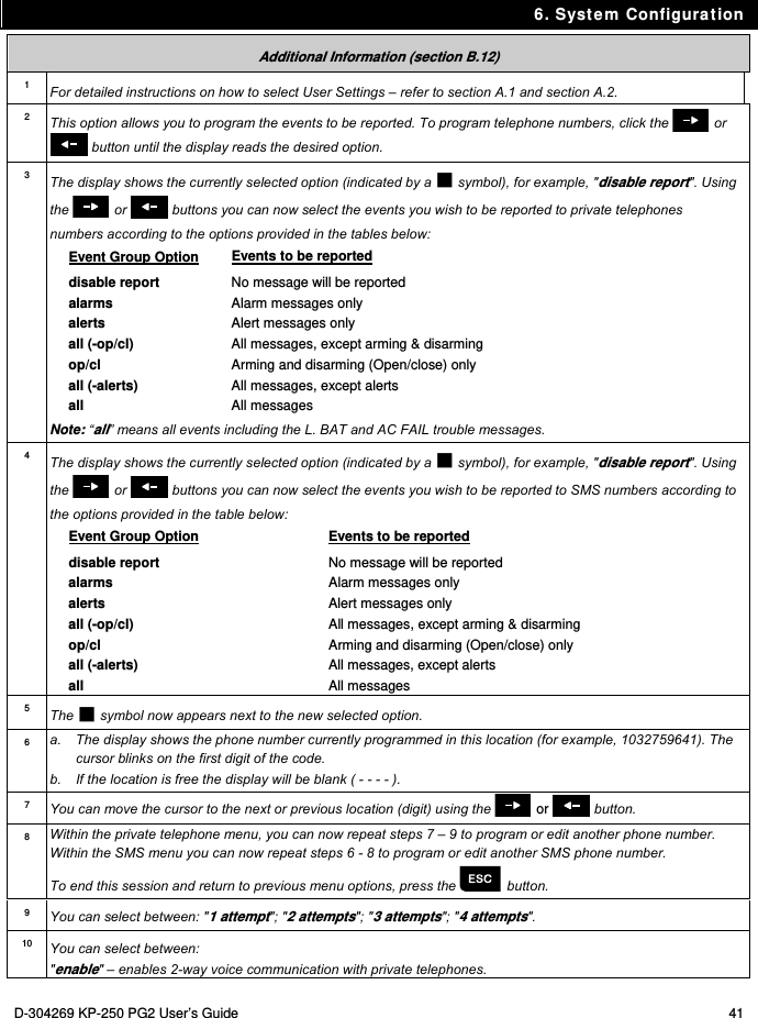
![6. System Configuration 38 D-304269 KP-250 PG2 User’s Guide REPORTED EVENTS disable report The display shows the currently selected option. 4. or Click the or button until the display reads the event group you wish to be reported via private phones, for example, [alarms]. 3 REPORTED EVENTS alarms 5. When you are satisfied with the setting, press to confirm. REPORTED EVENTS alarms A "Happy Tune" ☺ sounds. The display confirms the set events to be reported. 5, 12 ☺ B. To Program a Private Phone 6. REPORTED EVENTS alarms Click the or button until the display reads the desired Telephone No. you wish to program or edit, for example, "Private tel#2", and press . or 7. Private tel#2 8. Private tel#2 8032759333 To program or edit the phone number, at the blinking cursor position enter the phone number, for example, “8032759333”, using the numerical keypad. 6, 7 9. When done, press to confirm. Private tel#2 8032759333 A "Happy Tune" ☺ sounds and the display confirms the telephone number. 8, 12 C. To Program the Number of Redial Attempts 10. Private tel#2 Click the or button until the display reads [REDIAL ATTEMPTS] and press . or 11. REDIAL ATTEMPTS 3 alarms REDIAL ATTEMPTS 3 alarms The display shows the currently selected option. 12. or Click the or button until the display reads the desired number of redial attempts, for example, "4 attempts". 9 REDIAL ATTEMPTS 4 alarms](https://usermanual.wiki/Visonic/KP250PG2/User-Guide-2406625-Page-38.png)
![6. System Configuration D-304269 KP-250 PG2 User’s Guide 39 13. When you are satisfied with the setting, press to confirm. REDIAL ATTEMPTS 4 alarms A "Happy Tune" ☺ sounds. The display confirms the set number of redial attempts. 5, 12 D. To Program two-way voice communication 14. REDIAL ATTEMPTS 4 attempts Click the or button until the display reads [Two Way Voice] and press . or Two way voice enable 15. Two way voice enable The display shows the currently selected option. 16. or Click the or button to select the voice communication method, for example, "disable". 10 Two way voice disable 17. When you are satisfied with the setting, press to confirm. Two way voice disable A "Happy Tune" ☺ sounds. The display confirms the desired two-way voice communication method. 5, 12 E. To Program the Acknowledge Method 18. Two way voice disable Click the or button until the display reads [TEL. ACKNOWLEDGE] and press to confirm. or TEL.ACKNOWLEDGE by single ack 19. TEL.ACKNOWLEDGE by single ack The display shows the currently selected option. 20. or Click the or button until the display reads the desired acknowledge method, for example, "by all ack". 11 TEL.ACKNOWLEDGE by all ack 21. Refers to system that is connected to the Voice Box](https://usermanual.wiki/Visonic/KP250PG2/User-Guide-2406625-Page-39.png)
![6. System Configuration 40 D-304269 KP-250 PG2 User’s Guide TEL.ACKNOWLEDGE by all ack A "Happy Tune" ☺ sounds and the display confirms the set acknowledge method. 5, 12 SMS REPORT A. To Program Events to be Reported by SMS 1. SMS REPORT Enter the [USER SETTINGS] menu, select the [SMS REPORT] option and press . 1 2. REPORTED EVENTS disabled When the display reads [REPORTED EVENTS] press . REPORTED EVENTS disabled The display shows the currently selected option. 3. or Click the or button until the display reads the event group you wish to be reported via SMS, for example, [alarms]. 4 REPORTED EVENTS alarms 4. When you are satisfied with the setting, press to confirm. REPORTED EVENTS alarms A "Happy Tune" ☺ sounds and the display confirms the set events to be reported. 5, 12 B. To Program SMS Telephone Numbers 5. REPORTED EVENTS disabled Click the or button until the display reads the SMS phone number you wish to program or edit, for example, "SMS tel#2", and press . or 6. SMS tel#2 7. SMS tel#2 To program or edit the phone number, at the blinking cursor position enter the SMS phone number, for example, “5080168593”, using the numerical keypad. 6, 7 8. When done, press to confirm. SMS tel#2 5080168593 A "Happy Tune" ☺ sounds and the display confirms the SMS phone number. 8, 12](https://usermanual.wiki/Visonic/KP250PG2/User-Guide-2406625-Page-40.png)
![6. System Configuration 42 D-304269 KP-250 PG2 User’s Guide "disable" - disables 2-way voice communication with private telephones. 11 You can select between: "by single ack" – an acknowledge signal from only a single telephone will stop the reporting process. "by all ack" – an acknowledge signal from all telephones is required to stop the reporting process. 12 You can now, select other options, end this session – (see section A.1 and section A.2), or quit programming (see section A.3). B.13 Enabling / Disabling the Squawk Option The PowerMaster system (and its wireless sirens) can be set to produce a short "Squawk" of audible feedback to assist you when you use your keyfob to arm (1 beep) and disarm (2 beeps) the PowerMaster system (operates in a similar manner to a car alarm). Here you can enable / disable the Squawk. Carefully read the section titled "Additional Information" according to the indicated references1 etc – see table at end of this section. 1. SQUAWK on Enter the [USER SETTINGS] menu, select the [SQUAWK] option and press . 1 SQUAWK on The display shows the currently selected setting. 2 2. or Click the or button until the display reads the desired setting, for example, "off" and press the button to confirm. SQUAWK off 3. SQUAWK off A "Happy Tune" ☺ sounds and The display confirms the saved setting. 3, 4 Additional Information (section B.13) 1 For detailed instructions on how to select User Settings – refer to section A.1 and section A.2. 2 a. The display shows the currently selected setting (indicated by a symbol), for example, [SQUAWK on]. b. You can now enable (ON) or disable (OFF) the Squawk option using the or button. 3 The symbol now appears next to the new selected option. 4 You can now select another option in the User Settings menu (see section A.1 and section A.2), or quit programming (see section A.3).](https://usermanual.wiki/Visonic/KP250PG2/User-Guide-2406625-Page-42.png)
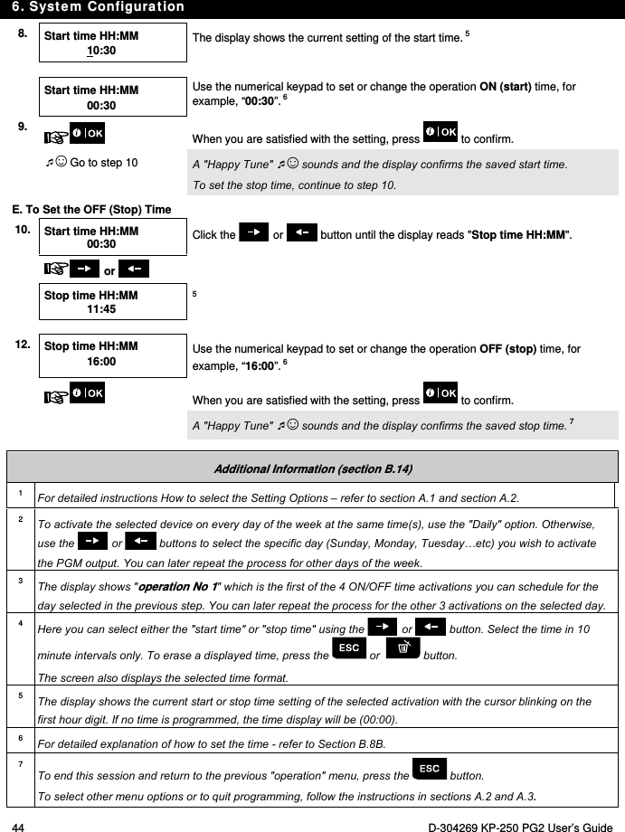
![6. System Configuration D-304269 KP-250 PG2 User’s Guide 43 B.14 Programming the Scheduler The PowerMaster system includes a PGM output that can be used to open and close an electrically-controlled gate, or to control a preferred electrical device via keyfobs or according to a programmable weekly time schedule. Here you can schedule the PGM output for up to 4 different ON/OFF time activations per any desired day or days of the week. In addition, you can schedule a "Daily" schedule that applies to every day of the week. It is recommended to complete the Scheduler table (placed at the end of this section) before programming the Scheduler. Carefully read the section titled "Additional Information" according to the indicated references1 etc – see table at end of this section. A. To Select the Device No. 1. SCHEDULER Enter the [USER SETTINGS] menu, select the [SCHEDULER] option and press . 1 2. PGM When the display reads [PGM], press . B. To Set the Day 2 SUNDAY The 1st day of the scheduler is displayed. 3. or Click the or button until the display reads the day you wish to schedule or "Daily", for example, "Tuesday". 2 TUESDAY 4. When the "day" to schedule appears on the display, press . C. To Select the Activation No. 5. Operation No 1 The 1st operation (PGM output activation) of the scheduler is displayed. 3 or Click the or button until the display reads the operation you wish to schedule, for example, "operation No 3". Operation No 3 6. When the "operation No." to schedule appears on the display, press . D. To Set the ON (Start) Time 7. Start time HH:MM : The "start time" screen is shown on the display. 4 To set the start time of the selected operation, press the button.](https://usermanual.wiki/Visonic/KP250PG2/User-Guide-2406625-Page-43.png)
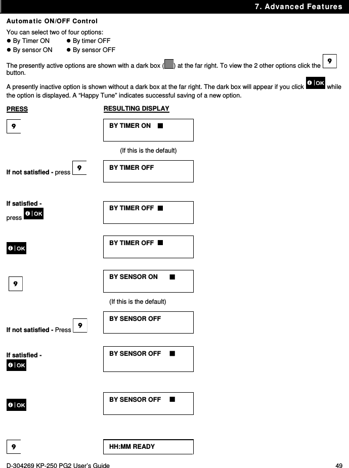
![6. System Configuration D-304269 KP-250 PG2 User’s Guide 45 Scheduler Table Device Device Description Day Operation 1 Operation 2 Operation 3 Operation 4 PGM Monday ON: _ _: _ _ OFF: _ _: _ _ ON: _ _: _ _ OFF: _ _: _ _ ON: _ _: _ _ OFF: _ _: _ _ ON: _ _: _ _ OFF: _ _: _ _ PGM Tuesday ON: _ _: _ _ OFF: _ _: _ _ ON: _ _: _ _ OFF: _ _: _ _ ON: _ _: _ _ OFF: _ _: _ _ ON: _ _: _ _ OFF: _ _: _ _ PGM Wednesday ON: _ _: _ _ OFF: _ _: _ _ ON: _ _: _ _ OFF: _ _: _ _ ON: _ _: _ _ OFF: _ _: _ _ ON: _ _: _ _ OFF: _ _: _ _ PGM Thursday ON: _ _: _ _ OFF: _ _: _ _ ON: _ _: _ _ OFF: _ _: _ _ ON: _ _: _ _ OFF: _ _: _ _ ON: _ _: _ _ OFF: _ _: _ _ PGM Friday ON: _ _: _ _ OFF: _ _: _ _ ON: _ _: _ _ OFF: _ _: _ _ ON: _ _: _ _ OFF: _ _: _ _ ON: _ _: _ _ OFF: _ _: _ _ PGM Saturday ON: _ _: _ _ OFF: _ _: _ _ ON: _ _: _ _ OFF: _ _: _ _ ON: _ _: _ _ OFF: _ _: _ _ ON: _ _: _ _ OFF: _ _: _ _ PGM Sunday ON: _ _: _ _ OFF: _ _: _ _ ON: _ _: _ _ OFF: _ _: _ _ ON: _ _: _ _ OFF: _ _: _ _ ON: _ _: _ _ OFF: _ _: _ _ PGM Daily ON: _ _: _ _ OFF: _ _: _ _ ON: _ _: _ _ OFF: _ _: _ _ ON: _ _: _ _ OFF: _ _: _ _ ON: _ _: _ _ OFF: _ _: _ _ B.15 Enabling / Disabling Voice Option The system allows you to enable or disable status-dependent, pre-recorded verbal messages that are heard over the connected voice box. Here you can enable / disable the Voice Option. Carefully read the section titled "Additional Information" according to the indicated references1 etc – see table at end of this section. 1. VOICE OPTION enable Enter the [USER SETTINGS] menu, select the [VOICE OPTION] option and press . 1 2. VOICE OPTION enable The display shows the currently selected setting. 2 Refers to system that is connected to the Voice Box](https://usermanual.wiki/Visonic/KP250PG2/User-Guide-2406625-Page-45.png)
![6. System Configuration 46 D-304269 KP-250 PG2 User’s Guide or Click the or button until the display reads the desired setting, for example, "disable" and press to confirm. VOICE OPTION disable 3 3. A "Happy Tune" ☺ sounds and the display confirms the saved setting.4, 5 Additional Information (section B.15) 1 For detailed instructions on how to select the Setting Options – refer to section A.1 and section A.2. 2 a. The display shows the currently selected setting (indicated by a symbol), for example, "enable". b. You can now enable or disable the voice option using the or button. 3 The symbol now appears next to the newly selected option. 4 You can now select another option in the User Settings menu (see section A.1 and section A.2), or quit programming (see section A.3). 5 If you have selected "enable", make sure that the voice prompts can be heard over the panel loudspeaker by pressing the key on the KP-250 PG2 keypad. B.16 Adjusting the Volume of the Control Panel or External Box The KP-250 PG2 allows you to adjust the volume of the PowerMaster control panel or an external voice box. Here you can increase or decrease the loudness. Carefully read the section titled "Additional Information" according to the indicated references1 etc – see table at end of this section. 1. PANEL VOLUME Enter the [USER SETTINGS] menu, select the [PANEL VOLUME] option and press . 1 2. PANEL VOLUME 2 or Click the or button repeatedly to increase or decrease the loudness. PANEL VOLUME 3 3. A "Happy Tune" ☺ sounds and the display confirms the saved setting.4 Refers to a control panel that is connected to the Voice Box](https://usermanual.wiki/Visonic/KP250PG2/User-Guide-2406625-Page-46.png)
![6. System Configuration D-304269 KP-250 PG2 User’s Guide 47 Additional Information (section B.16) 1 For detailed instructions on how to select the Setting Options – refer to section A.1 and section A.2. 2 The display shows the currently selected setting (indicated by a symbol). 3 indicates the lowest volume level and indicates the highest. 4 You can now select another option in the User Settings menu (see section A.1 and section A.2), or quit programming (see section A.3). B.17 Serial Number The SERIAL NUMBER menu enables reading the system serial number and similar data for support purposes only. Here you can read the system serial number and other relevant data. Carefully read the section titled "Additional Information" according to the indicated references1 etc – see table at end of this section. 1. SERIAL NUMBER Enter the [USER SETTINGS] menu, select the [SERIAL NUMBER] option and press . 1 2. PRODUCT SN 0907030000. Displays the control panel serial number. 3. SW CAT & SN JS702275 K18.022 Displays the control panel software version. 4. LCD CAT SN JS700421 v1.0.02 Displays the control panel keypad software version. 2 5. PANEL ID 100005 Displays the control panel ID for PowerManage connectivity. 6. PYTHON VERSION FFFFFFFFF Displays the GSM image transfer software version. 7. EE CAT & SN J-702271 K18.022 Displays the control panel default version. 8. KP250 SW VER 01.00.09 Displays the KP-250 PG2 keypad software version.](https://usermanual.wiki/Visonic/KP250PG2/User-Guide-2406625-Page-47.png)
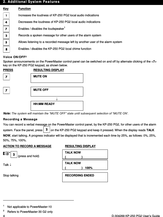
![8. Periodic Test by User Code 50 D-304269 KP-250 PG2 User’s Guide PRESS RESULTING DISPLAY 8. Periodic Test by User Code The components of your security system are designed to be maintenance-free as much as possible. Nevertheless, it is mandatory to test the system at least once a week and after an alarm event to verify that all system sirens, detectors, keyfobs, keypads and other peripherals function properly. Proceed as described in this section and if there is any problem, notify your installer at once. The test is performed in three parts: Siren Test: Each siren of the system is automatically activated for 3 seconds (outdoor sirens with low volume). In addition, the system tests the siren of enrolled smoke sensors. Temperature Sensor Test: When Temperature Sensors are enrolled in the system, the KP-250 PG2 displays the temperature of each zone in Celsius or Fahrenheit. Other Device Test: Each of the other devices in the system is activated by the user and the display indicates which devices were not yet tested. The "it's me" indication helps to identify the untested devices if necessary. A counter also indicates the number of devices that remain untested. Carefully read the section titled "Additional Information" according to the indicated references1 etc – see table at end of this section. A. To Enter the Periodic Test Menu 1. HH:MM READY Make sure the system is disarmed and then press the button repeatedly until the display reads "PERIODIC TEST" and press . 1 PERIODIC TEST 2. PRESENT TAG OR ENTER CODE: The screen will now prompt you to enter your user code or present your proximity tag. 3. CODE/TAG Enter your User Code or present your proximity tag. 2 3 ☺ Go to step 4 B. To Test the Sirens 4. SIRENS TEST The display now reads [SIREN TEST]. 5. To initiate the siren test press . Immediately after pressing , all 4 LEDs on the panel and all 5 LEDs on the KP-250 PG2 should light (LED test). 4 SIREN P <NEXT> or <OK> The display now reads [SIREN P], where "P" indicates the control panel siren that](https://usermanual.wiki/Visonic/KP250PG2/User-Guide-2406625-Page-50.png)
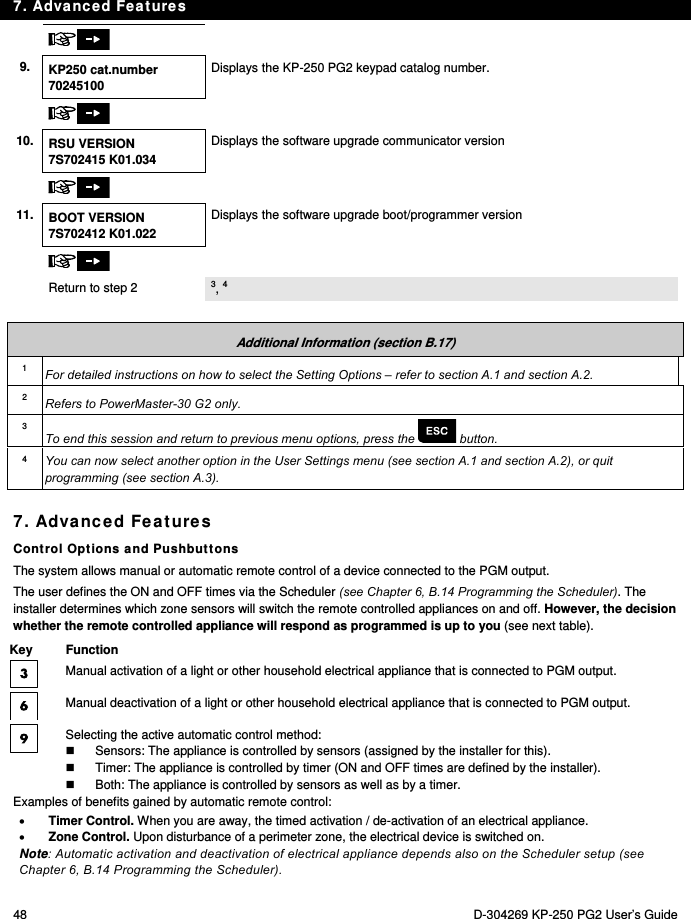
![8. Periodic Test by User Code D-304269 KP-250 PG2 User’s Guide 51 is currently being tested. First the panel siren sounds for 3 seconds after which the PowerMaster system will automatically repeat the procedure for the next siren enrolled in the system until all sirens are tested. 5 You should listen to the sirens sounds and make sure that all sirens sound. Once all the sirens have been tested, the control panel will now test the sirens of smoke sensors that are enrolled in the alarm system. The display now reads [Zxx: SMOKE SIREN] on the first line, and [<NEXT or <OK>] on the second line, where "Zxx" indicates the zone number of the smoke sensor. During this time, the siren of the tested smoke sensor will sound for up to one minute. Press to test the siren of the next smoke sensor. 6. SIREN TEST ENDED When all the sirens test is complete, the display reads [SIREN TEST ENDED]. Press the or the button to confirm the test and then move to the next step for zone temperature display. or C. To Display the Temperature 7. TEMPERATURE TEST The display now reads [TEMPERATURE TEST]. 8. To display the temperature of zones on the KP-250 PG2, press . 6 Z01 +19.5C Z01:Temp. Sensor The KP-250 PG2 reads the temperature of each zone. The display alternates between the temperature, the sensor number and the sensor location. 7 Repeatedly click the button to review the temperature of each zone (by Temperature Sensor). Z01 +19.5C Living room 9. DEVICE TESTS END When the temperature of all zones has been reviewed, the display reads [DEVICE TESTS END]. Press the or the button to confirm the test and then move to the next step to test the other devices. or D. To Test all other Devices TEST ALL DEVICES The display now reads [TEST ALL DEVICES]. 10. To enter the devices test procedure, press . 11. NOT ACTIVE NNN The display reads [NOT ACTIVE NNN]. NNN indicates the number of enrolled devices in the panel that have not been tested yet. This number automatically drops one count for every tested device. To initiate devices test, press . Z01 NOT ACTIVE The display shows the 1st device in the list of untested devices. The display](https://usermanual.wiki/Visonic/KP250PG2/User-Guide-2406625-Page-51.png)
![8. Periodic Test by User Code 52 D-304269 KP-250 PG2 User’s Guide Z01 CONTACT alternates between the device number, the device type (e.g. magnetic contact, keyfob, keypad, etc.), and the device location. The test is performed by activating each device as explained in point 8 in the table below. Z01 NOT ACTIVE FRONT DOOR Z01 IS ACTIVATE Z01 CONTACT Once the device has been activated, the display will change accordingly. 12. Click to scroll through the list of all untested devices. 9 13. DEVICE TESTS END When all devices have been activated, the display reads [DEVICE TESTS END] followed by [HH:MM READY]. HH:MM READY Additional Information (Periodic Test) 1 Display shown in disarm state when all zones are secured (00:00 or other digits show present time). 2 If you have not already changed your personal code number, use the default setting – 1111. 3 If the INSTALLER CODE is used to enter the Periodic Test instead of the USER CODE, the devices LED will also provide the link quality indication – refer to Chapter 4 of the KP-250 PG2 Installer’s Guide, Periodic Test by Installer Code. 4 To skip the SIRENS TEST and select the other devices TEST, press . 5 The Periodic test can be performed on a maximum of two wireless sirens (including one internal sounder) and the sirens of enrolled smoke sensors. Outdoor sirens are activated with low volume. 6 If no temperature sensor is enrolled in the system, the display reads "NO EXISTING DEV.". 7 The displayed temperature can be in Celsius or Fahrenheit according to the programmed settings of the Temperature Sensor. 8 To activate system devices during the "Periodic Test"; make sure the device LED lights when activated: Contact sensor: Open or close the door or window protected by the contact. Motion sensors: Perform a "walk test" of the detector as explained in the detector's datasheet. Smoke sensors: Perform a "Diagnostic test" as explained in the detector's datasheet. Keyfob: Activate any of the keyfob buttons. Keypads: Press the keypad’s button. Other devices: In general, follow the "Diagnostic Tests" described in the device's datasheet or activate any of its functions. 9 a. Three seconds after the device is displayed, the device LED blinks to assist you to identify ("it's me"). b. To end the session, press the button until the display reads [<OK> TO LEAVE] then press .](https://usermanual.wiki/Visonic/KP250PG2/User-Guide-2406625-Page-52.png)
![8. Periodic Test by User Code D-304269 KP-250 PG2 User’s Guide 53 Periodic Test per Partition In addition to the regular Periodic Test, you can also test zones for enrolled sensors (excluding temperature sensors and sirens) that are assigned to a selected partition. To conduct the periodic Test per Partition 1 1. HH:MM READY TROUBLE Make sure the selected partition is disarmed and the other partitions are not in exit or entry delay and then press the partition ( ) button. 2. SELECT PARTITION When the display reads [SELECT PARTITION], press the partition number of the zones you wish to test, for example, (Partition 1). 3. PARTITION 1 N.RDY MEMORY PARTITION 1 N.RDY TROUBLE 4. Press the button repeatedly until the display reads [PERIODIC TEST] and press . PERIODIC TEST 5. PRESENT TAG OR ENTER CODE The screen will now prompt you to or enter your Master user code. 2 6. Enter Master user code P1 SENSORS TEST 3 7. 8. NOT ACTIVE NNN The display reads [NOT ACTIVE NNN]. NNN indicates the number of enrolled devices in the panel that have not been tested yet. This number automatically drops one count for every tested device. Test per partition is performed by activating each device as explained in point 4 in the Additional Information table below. After a device has been activated, the control panel reads [Zxx IS ACTIVATED] and the "N" indicator drops one count. After all devices have been tested, the control panel reads [DEVICE TESTS END]. DEVICE TESTS END](https://usermanual.wiki/Visonic/KP250PG2/User-Guide-2406625-Page-53.png)
![8. Periodic Test by User Code 54 D-304269 KP-250 PG2 User’s Guide 9. Press . 5 ☺ Return to step 3 Additional Information (Periodic Test per Partition) 1 Partitioning must be enabled by your installer. 2 If you have not already changed your personal code number, use the default setting – 1111. 3 To abort, press the button; the display reads [<OK> TO Exit]. Press the button. 4 To activate system devices during the "Periodic Test"; make sure the device LED lights when activated: Contact sensor: Open or close the door or window protected by the contact. Motion sensors: Perform a "walk test" of the detector as explained in the detector's datasheet. Smoke sensors: Perform a "Diagnostic test" as explained in the detector's datasheet. 5 Periodic test per partition will be interrupted (the panel returns to selected partition display) upon occurrence of one of the following: 1) Disarm event by keyfob, keypad or pendant assigned to a selected partition; 2) PANIC, FIRE or EMERGENCY event.](https://usermanual.wiki/Visonic/KP250PG2/User-Guide-2406625-Page-54.png)
![9. Maintenance D-304269 KP-250 PG2 User’s Guide 55 9. Maintenance Replacing Wireless Devices Batteries The wireless devices supplied with your system are powered by batteries that last several years, in normal use. However, if and when a battery becomes weak, the device itself sends a “low battery” message to the control panel, and a low battery trouble message is displayed together with the zone information (see Chapter 5 – Trouble Indications). The respective manuals of these sensors or devices should be consulted for proper battery replacement guidelines to be performed by the installer. Accessing 24-Hour Zones To access a sensor defined as a 24-hour zone without causing an alarm: Click - the display will read: USER SETTINGS. Click - the display will read: PRESENT TAG OR ENTER CODE ___. Key your secret 4-digit <User Code> or present your tag - the buzzer will play the “happy Tune” (- - - ––––). You have 4 minutes during which the 24-hour sensor can be opened and accessed. When the 4 minutes are up, the system will automatically revert to the normal mode. Event Log by User Code All events are memorized in an event log that contains up to 100 entries. You can access this log, review the events one by one and draw functional conclusions. Note: Up to 250 (PowerMaster-10 G2) / 1000 (PowerMaster-30 G2 / PowerMaster-33 G2) events are stored in the event log that can be reviewed via the Remote Programmer PC software application or by the remote PowerManage server. If the event log fills up completely, the oldest event is deleted upon registration of each new event. The date and time of occurrence are memorized for each event. When reading the event log, events are shown in chronological order - from the newest to the oldest. The event description is shown with the date and time. The display is shown several times, until you click to move on to an older event, or until the “no action” 4-minute timeout restores the system to the normal operating mode. Access to the event log is provided by clicking the button and then keying your master user code. To get an overall view of using the log, refer to the procedure below. To read the event log, proceed as follows: HH:MM READY 1. PRESENT TAG OR ENTER CODE: 2. CODE When the KP-250 PG2 display reads [PRESENT TAG OR ENTER CODE: ], enter the current master user code or present your tag. KP-250 LIST OF EVENTS The "Happy Tune" will sound and the display will read [KP-250 LIST OF EVENTS]. (see Important Note!)](https://usermanual.wiki/Visonic/KP250PG2/User-Guide-2406625-Page-55.png)
![9. Maintenance 56 D-304269 KP-250 PG2 User’s Guide 3. Click the button. The latest event will be shown. CPU LOW BATTERY 12/04/11 15:14 The event is displayed on two rows, for example, "CPU LOW BATTERY" then "12/04/11 15:14". The display will be shown until clicking again to move to the next event or until the event log times out (4 minutes). F03 DISARM 15/03/11 08:37 4. Click the button as many times as necessary to read all the required data. Important Note! Entering an incorrect code 5 times in a row will initiate a 30-second penalty lockout of the keypad. Attention: The system will not allow you to erase the event log. Only the installer is authorized to view and perform this function. Exiting the Event Log 1. Click the button from anywhere within the event log. The display will read [KP-250 <OK> TO EXIT]. KP-250 <OK> to Exit 2. Click the button. HH:MM READY The system reverts to the normal operating mode.](https://usermanual.wiki/Visonic/KP250PG2/User-Guide-2406625-Page-56.png)