User Manual

D-304269 KP-250 PG2 User’s Guide 1
KP-250 PG2
Advanced Two-Way Keypad
User’s Guide
Table of Contents
1. Introduction ................................................................................................................................................................. 3
2. Additional System Features ........................................................................................................................................ 3
Partitioning .............................................................................................................................................................. 3
Screen Saver .......................................................................................................................................................... 3
Proximity Tags ........................................................................................................................................................ 3
Users and Codes .................................................................................................................................................... 3
Speech & Sound Cont. Push-buttons ..................................................................................................................... 3
Voice ON/OFF ........................................................................................................................................................ 4
Recording a Message ............................................................................................................................................. 4
Message Playback .................................................................................................................................................. 5
3. Arming and Disarming the System ............................................................................................................................. 6
Basic Arming and Disarming................................................................................................................................... 6
Special Arming & Disarming Options ...................................................................................................................... 7
Initiating Alarms .................................................................................................................................................... 10
4. System Status and Indications ................................................................................................................................. 13
LCD Display and General Audible Indicators ........................................................................................................ 13
Arming Indications ................................................................................................................................................ 13
General Indications ............................................................................................................................................... 14
Alarm Indication Siren ........................................................................................................................................... 15
5. Reviewing Troubles and Alarm Memory ................................................................................................................... 16
Alarm & Tamper Memory Indication ..................................................................................................................... 16
Clearing the Memory Indication ............................................................................................................................ 16
Troubles ................................................................................................................................................................ 16
GSM/GPRS Status Indications ............................................................................................................................. 17
Trouble Indications ............................................................................................................................................... 18
6. System Configuration ............................................................................................................................................... 19
A.1 Entering the User Settings Menu & Selecting a Setting Option ...................................................................... 19
A.2 Returning to the Previous Step or Exiting the USER SETTINGS Menu ......................................................... 21
A.3 Buttons used for Navigation & Setting ............................................................................................................ 22
B.1 Setting the Zone Bypass Scheme .................................................................................................................. 22
B.2 Reviewing the Zone Bypass Scheme ............................................................................................................. 24
B.3 Recalling the Zone Bypass Scheme ............................................................................................................... 24
B.4 Programming User Codes .............................................................................................................................. 25
B.5 Programming the Duress Code ...................................................................................................................... 27
B.6 Add / Delete Proximity Tags ........................................................................................................................... 28
B.7 Add / Delete Keyfob Transmitters ................................................................................................................... 30
B.8 Setting the Time & Time Format ..................................................................................................................... 33
B.9 Setting the Date & Date Format ..................................................................................................................... 35
B.10 Enabling / Disabling Auto-Arming ................................................................................................................. 36
B.11 Setting the Auto-Arming Time ...................................................................................................................... 36
B.12 Programming Private Phone and SMS Reporting ........................................................................................ 37
B.13 Enabling / Disabling the Squawk Option ...................................................................................................... 42
2 D-304269 KP-250 PG2 User’s Guide
B.14 Programming the Scheduler ......................................................................................................................... 43
B.15 Enabling / Disabling Voice Option ................................................................................................................ 45
B.16 Adjusting the Volume of the Control Panel or External Box .......................................................................... 46
B.17 Serial Number ............................................................................................................................................... 47
7. Advanced Features ................................................................................................................................................... 48
Control Options and Pushbuttons ......................................................................................................................... 48
Automatic ON/OFF Control ................................................................................................................................... 49
8. Periodic Test by User Code ...................................................................................................................................... 50
Periodic Test per Partition ..................................................................................................................................... 53
9. Maintenance ............................................................................................................................................................. 55
Replacing Wireless Devices Batteries .................................................................................................................. 55
Accessing 24-Hour Zones ..................................................................................................................................... 55
Event Log by User Code ....................................................................................................................................... 55
Exiting the Event Log ............................................................................................................................................ 56
APPENDIX A: Specifications ........................................................................................................................................ 57
APPENDIX B: Partitioning ............................................................................................................................................ 57
B1. Selecting a Partition ........................................................................................................................................ 57
B2. Arming / Disarming the System ...................................................................................................................... 57
B3. The Show Function ......................................................................................................................................... 58
B4. Siren ............................................................................................................................................................... 58
B5. Partition Status display ................................................................................................................................... 58
B6. Common Areas ............................................................................................................................................... 58
APPENDIX C: Glossary ................................................................................................................................................ 60
APPENDIX D: Compliance with Standards .................................................................................................................. 63

1. Introduction
D-304269 KP-250 PG2 User’s Guide 3
1. Introduction
KP-250 PG2 is a 2-way wireless PowerG keypad display device for use with the PowerMaster-10 G2 / PowerMaster-30 G2 /
PowerMaster-33 G2 control panel (version 18 and higher). Up to 10 KP-250 PG2 keypads can be enrolled in the
PowerMaster system. The PowerMaster-10 G2 / PowerMaster-30 G2 / PowerMaster-33 G2 is a highly advanced wireless
alarm control panel produced by Visonic Ltd.
2. Additional System Features
Partitioning
Partitioning allows you to divide the system into three independently controllable areas with different users assigned to
each partition whereby each user can arm the partition to which they are assigned. For detailed information on
Partitioning, see APPENDIX B.
Screen Saver
For security reasons, it is sometimes required to hide the status indication (LCD and LED display) on the KP-250 PG2
keypad from a potential intruder.
When operated by AC power and the Screen Saver option is enabled by the installer, then if no key is pressed for more
than 30 seconds, the screen saver will turn on and the LEDs will stop indicating any status.
When operated by batteries and the Screen Saver option is enabled by the installer, then if no key is pressed for more
than 10 seconds, the display will turn off and the LEDs will stop indicating any status.
Pressing any key will resume the normal status display. Pressing the Fire, Emergency or Panic keys will also initiate the
Fire, Emergency or Panic alarm.
If configured by the installer for additional security, the system will ask you to enter your user code or to present your
proximity tag before resuming the normal display.
When partition is enabled, the installer can configure the system so that if no key is pressed during more than 30
seconds the date and time will appear on the display.
Proximity Tags
Your system responds to valid proximity tags enrolled to the system. The proximity tag enables you to perform a variety
of functions without entering a user code, for example, arming, disarming, reading the event log, etc.
1. Whenever the user code is required, you can simply present a valid proximity tag and perform the desired operation
without the need to key-in your user code.
- OR -
2. When the system is disarmed and after presenting a valid proximity tag to the KP-250 PG2 keypad, the message
"<OK> for AWAY" is displayed. Now you can press the button to immediately arm the system, or, press the
button once / twice – the message “<OK> for HOME” / “<OK> for disarm” is displayed – and then press the
button for HOME arming / disarming.1
Note: If you do not press the button (wait for 3 seconds), the system automatically arms AWAY and the display
will read "ARMING AWAY PLEASE EXIT NOW". Presenting the proximity tag once again will DISARM the system.
Users and Codes
Security codes are used mainly to arm and disarm the system or to access information that is restricted only to
authorized users (see Chapter 6, section B.4, Programming User Codes).
Speech & Sound Cont. Push-buttons
The sound and speech-related functions offered by the PowerMaster alarm system can be controlled by the KP-250
PG2 keypad, as detailed in the following list.
1 In option 2, the KP-250 PG2 keypad will not operate (respond) if the KP-250 PG2 is assigned to two or more partitions.
2. Additional System Features
4 D-304269 KP-250 PG2 User’s Guide
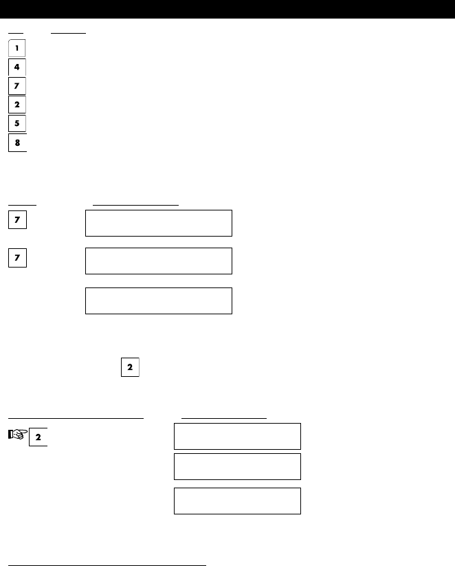
Key Function
Increases the loudness of KP-250 PG2 local audio indications
Decreases the loudness of KP-250 PG2 local audio indications
Enables / disables the loudspeaker1
Records a spoken message for other users of the alarm system
Allows listening to a recorded message left by another user of the alarm system
Enables / disables the KP-250 PG2 local chime function
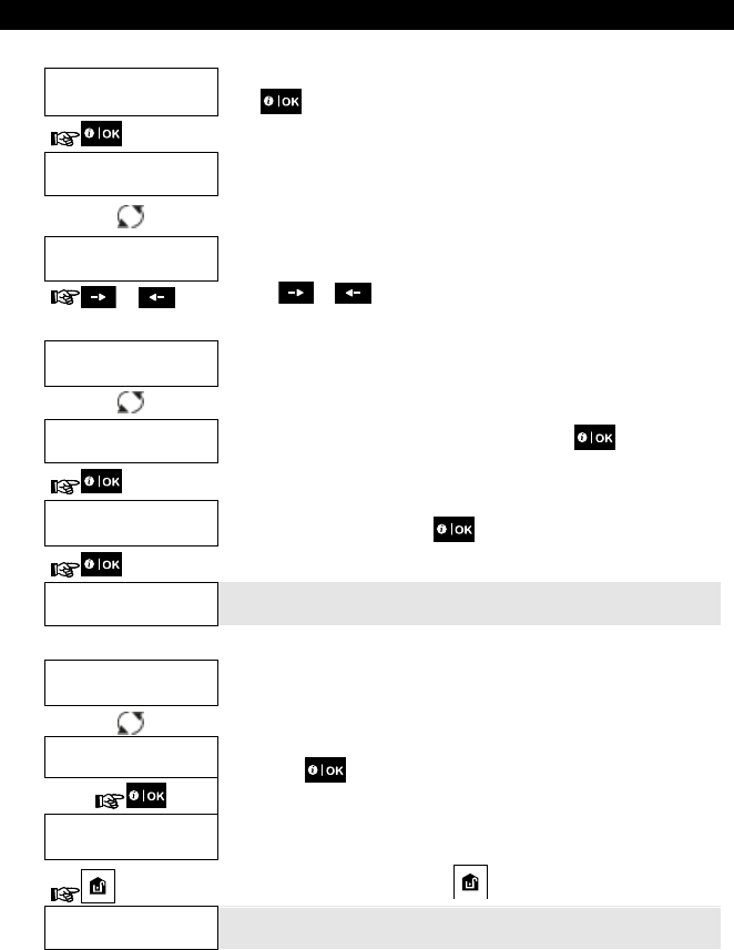
Voice ON/OFF2
Spoken announcements on the PowerMaster control panel can be switched on and off by alternate clicking of the <7>
key on the KP-250 PG2 keypad, as shown below.
PRESS RESULTING DISPLAY
MUTE ON
MUTE OFF
HH:MM READY
Note: The system will maintain the “MUTE OFF” state until subsequent selection of “MUTE ON’.
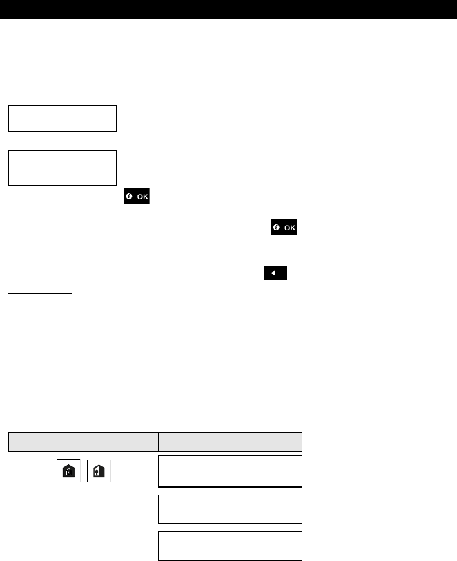
Recording a Message
You can record a verbal message on the PowerMaster control panel, by the KP-250 PG2, for other users of the alarm
system. Face the panel, press on the KP-250 PG2 keypad and keep it pressed. When the display reads TALK
NOW, start talking. A progress indicator will be displayed that is incremented each time by 25%, as follows: 0%, 25%,
50%, 75%, 100%.
ACTION TO RECORD A MESSAGE RESULTING DISPLAY
(press and hold) TALK NOW
( )
Talk TALK NOW
( ) 100%
Stop talking RECORDING ENDED
1 Not applicable to PowerMaster-10
2 Refers to PowerMaster-30 G2 only

2. Additional System Features
D-304269 KP-250 PG2 User’s Guide 5
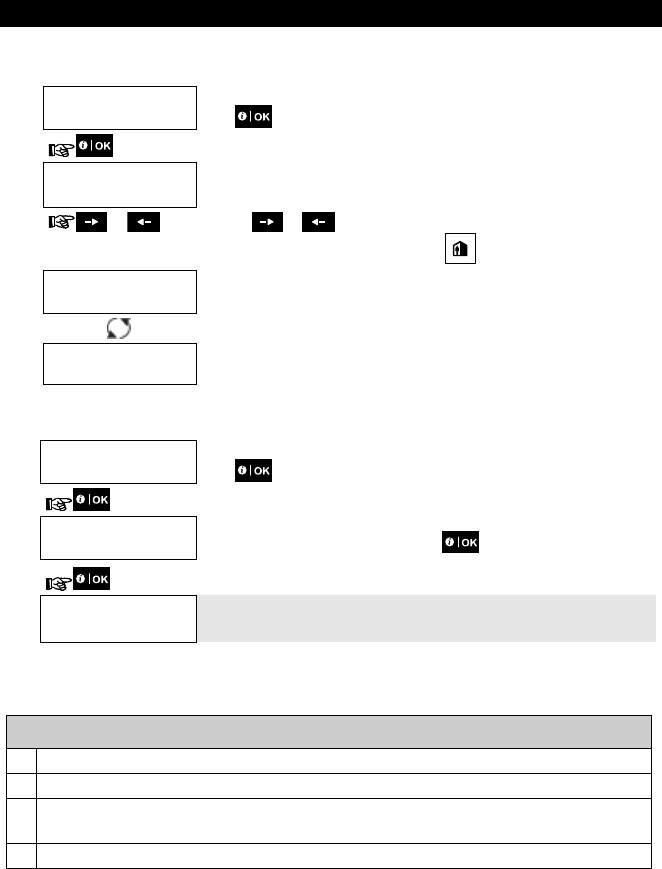
Once the progress indicator reaches 100%, RECORDING ENDED will be displayed.
When you release the button, the display will revert to the normal status-displaying mode, but will also indicate that a
message is waiting. For example:
HH:MM READY
MESSAGE
Note: The message icon ( ) will also flash on the bottom of the display.
Message Playback
Message playback is performed by the control panel. To listen to a message left by another user of the system:
Click on the KP-250 PG2 keypad and listen. PLAY will be displayed and the message will be played back over the
PowerMaster loudspeaker or external voice box. When the playback ends, the display will revert to the normal status-
displaying mode.
3. Arming and Disarming the System
6 D-304269 KP-250 PG2 User’s Guide
3. Arming and Disarming the System
Basic Arming and Disarming
Following are a set of procedures for performing basic arming and disarming of the alarm system.
Preparing to Arm
Before arming, make sure that READY is displayed on the KP-250 PG2 keypad.
HH:MM READY
This indicates that all zones are secured and you may arm the system as desired.
If at least one zone is open (disturbed) the display will read:
HH:MM NOT READY
This indicates that the system is not ready for arming and in most cases that one or more
zones are not secured. However, it can also mean that an unresolved condition exists
such as certain trouble conditions, jamming etc., depending on system configuration.
To review the open zones click on the KP-250 PG2 keypad. The details and location of the first open zone
detector (usually an open door or window sensor) will be displayed. To fix the open zone, locate the sensor and secure
it (close the door or window) – see "device locator" below. Each click of on the KP-250 PG2 keypad will display
another open zone or trouble indication. It is highly recommended to fix the open zone(s), thus restoring the system to
the state of “ready to arm”. If you do not know how to do this, consult your installer.
Note: To quit at any stage and to revert to the "READY" display, click on the KP-250 PG2 keypad.
Device Locator: The PowerMaster system has a powerful device locator that helps you to identify open or troubled
devices indicated on the LCD display. While the LCD displays an open or faulty device, the LED on the respective
device flashes indicating "it's me". The "it's me" indication will appear on the device within max. 16 seconds and will
last for as long as the LCD displays the device.
Arming ‘AWAY' / ‘HOME'
If the system is READY and/or Forced Arming is enabled proceed as shown below. For more information on Forced
Arming, see "Forced Arming AWAY or HOME" below.
If the system is NOT READY and Forced Arming is not permitted, review any open zone detectors to locate and secure
them.
If you want to arm using partitions, see "Partition Selection Process" and then proceed as shown below.
If the user has changed the state of the system from a high security mode to a lower security mode i.e. from ARM to
DISARM, or from AWAY to HOME, he will be prompted to enter the user code or to present his proximity tag thus
bypassing the QUICK ARM option.
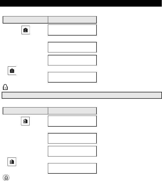
PRESS RESULTING DISPLAY
/
ARMING AWAY/HOME
If Quick Arm is disabled PRESENT TAG OR
ENTER CODE:
PLEASE EXIT NOW
Vacate the premises (ARM AWAY)
OR (Exit delay)
3. Arming and Disarming the System
D-304269 KP-250 PG2 User’s Guide 7
PRESS RESULTING DISPLAY
Move to interior zone (ARM HOME)
AWAY/HOME
ARM indicator on both the KP-250 PG2 keypad and PowerMaster panel lights steadily during the armed state.
Disarming and Stopping Alarm
Enter the protected premises via a delayed zone. Upon detecting your entrance, the system will start sounding the entry
delay beeps alerting you to disarm the system before the entry delay ends.
After disarming, different displays may appear indicating that the system is in a state of alarm MEMORY. The MEMORY
message will disappear only upon rearming the system. To disarm the system, proceed as shown:
PRESS RESULTING DISPLAY
PRESENT TAG OR
ENTER CODE:
Enter code / present tag Code / present tag
ARM indicator on both the KP-250 PG2 keypad and PowerMaster panel extinguishes during the disarmed state.
Disarming the system also stops the siren alarm, irrespective of whether the alarm was initiated during the armed or the
disarmed state.
Disarming under Duress
If you are forcibly compelled to disarm the system, enter the duress code (2580 by default) or another code set by the
installer. Disarming will take place normally but a silent alarm will be transmitted to the monitoring station.
Partition Selection Process
Access to any desired partition is achieved through the use of an individual code or proximity tag. It is not possible to
access the INSTALLER MENU if one or more partitions are in the AWAY or HOME modes.
Before attempting to perform any operation on any given partition(s), it is necessary to perform the operations below
which enable you to select the desired/allowed partition(s) using the individual code or proximity tag:
PRESS RESULTING DISPLAY
SELECT PARTITION
Enter partition # (1 - 3) PARTITION 1
Notes:
1. The “Sad Tune” will be heard when selecting a partition to which no sensors / peripherals were enrolled.
2. If a partition is enabled and no zones are assigned to the partition, the icon will appear on the KP-250
PG2 keypad display.
Special Arming & Disarming Options
In addition to basic arming, KP-250 PG2 provides you with several advanced arming and disarming options:
3. Arming and Disarming the System
8 D-304269 KP-250 PG2 User’s Guide
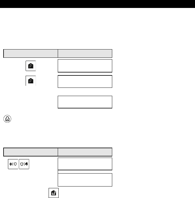
Switching from ‘HOME’ to ‘AWAY’
You do not have to disarm the system - just press . The response will be the same as in ARMING AWAY above.
Vacate the premises before the exit delay expires.
Switching from ‘AWAY’ to ‘HOME’
You do not have to disarm the system - just press . Since this operation reduces the security level, KP-250 PG2
will ask you to key in your master user code or user code, or to present your proximity tag, thus making sure that you
are an authorized user.
PRESS RESULTING DISPLAY
PRESENT TAG OR
ENTER CODE:
Enter code / present tag Code / present tag
ARMING HOME
Move to interior zone (Exit delay)
HH:MM HOME
ARM indicator flashes on both the KP-250 PG2 keypad and PowerMaster panel during the armed state.
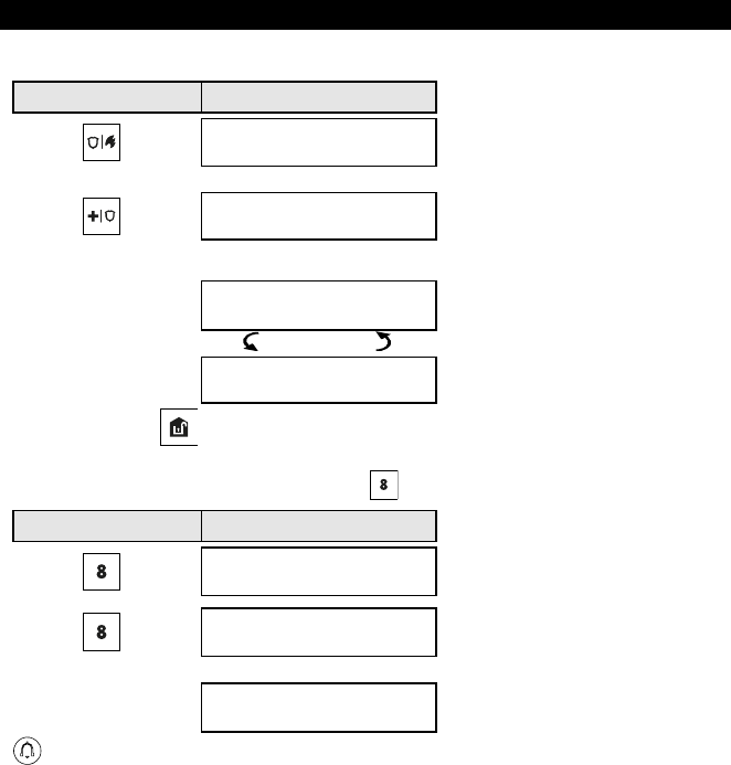
Arming AWAY or HOME ‘Instant’
Pressing during the exit delay will arm the system in the "Instant' mode, i.e. without an entry delay. Therefore, any
detection in any zone will trigger an immediate alarm. To arm AWAY-INSTANT, proceed as follows.
PRESS RESULTING DISPLAY
PRESENT TAG OR
ENTER CODE:
Enter code / present tag Code / present tag
ARMING AWAY
ARMING INSTANT
PLEASE EXIT NOW
Vacate the premises (Exit delay)
AWAY
ARM indicator on both the KP-250 PG2 keypad and PowerMaster panel lights during the armed state.
Forced Arming AWAY or HOME
Forced arming allows you to arm the system even if the system is "NOT READY". Any open zones will be bypassed for
the duration of arming.
Note: When forced arming is carried out, the buzzer “protests” by emitting a continuous tone during the exit delay until
3. Arming and Disarming the System
D-304269 KP-250 PG2 User’s Guide 9
the last 10 seconds of the delay. You can silence this signal by pressing the arming button again.
If forced arming is enabled and you wish to arm the system when NOT READY is displayed, proceed as shown:
PRESS RESULTING DISPLAY
PRESENT TAG OR
ENTER CODE:
Enter code / present tag Code / present tag
ARMING AWAY
PLEASE EXIT NOW
(to mute the buzzer)
Vacate the premises
(Exit delay)
AWAY
ARM indicator on both the KP-250 PG2 keypad and PowerMaster panel lights during the armed state.
Remember: Forced arming compromises security!!
Forced arming “HOME” is performed in a similar manner, as follows:
PRESS RESULTING DISPLAY
PRESENT TAG OR
ENTER CODE:
Enter code / present tag Code / present tag
ARMING HOME
PLEASE EXIT NOW
(to mute the buzzer)
Vacate the premises
(Exit delay)
HH:MM HOME
ARM indicator on both the KP-250 PG2 keypad and PowerMaster panel flashes during the armed state.
3. Arming and Disarming the System
10 D-304269 KP-250 PG2 User’s Guide
Arming in the Latchkey Mode
This mode, if enabled by the installer, is useful for a parent at work who wants to be sure that his children have returned
from school and have disarmed the system. A special “latchkey” message will be sent out when the system is disarmed
by a “latchkey user”.
Latchkey users are holders of user codes or users of keyfob transmitters 5-8 (PowerMaster-10 G2) / 23-32
(PowerMaster-30 G2 / PowerMaster-33 G2). The latchkey message is considered an alert and not an alarm, and is
therefore sent to the private telephones programmed by the user as targets for alert messages.
Latchkey arming is possible only when you arm “AWAY”. To arm in the Latchkey mode, proceed as follows:
PRESS RESULTING DISPLAY
ARMING AWAY
ARMING LATCHKEY
PLEASE EXIT NOW
Vacate the premises (Exit delay)
AWAY
Note: Latchkey must be enabled by your installer.
ARM indicator on both the KP-250 PG2 keypad and PowerMaster panel lights during the armed state.
Initiating Alarms
Following are various methods that may be used for initiating alarms.
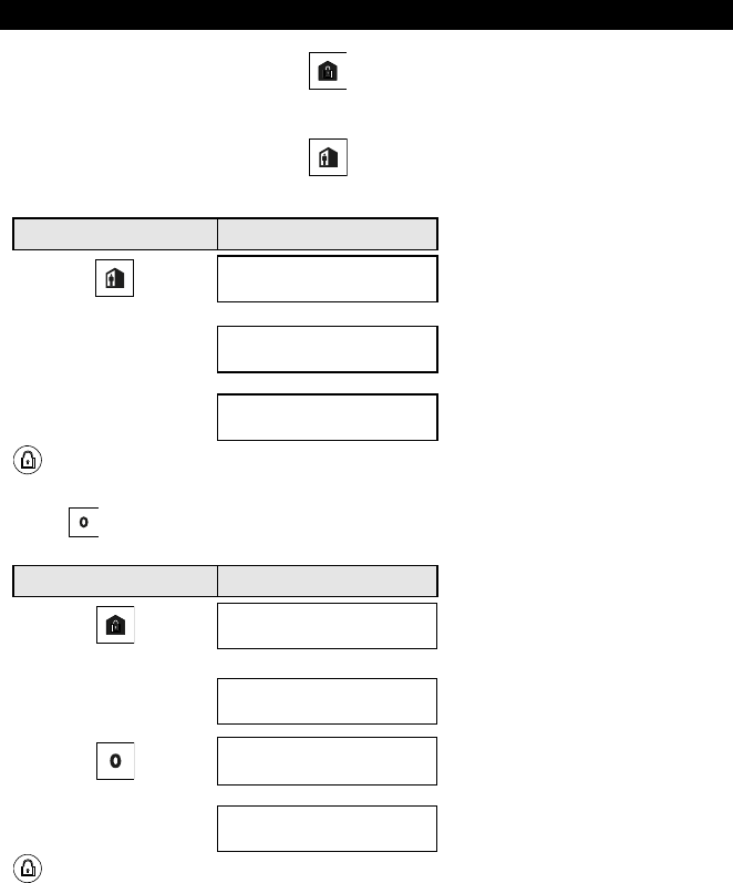
Initiating Panic Alarm
You can generate a panic alarm manually in the disarmed and armed states. The sequence will be as shown:
PRESS RESULTING DISPLAY
simultaneously
for 2 seconds
PANIC ALARM
HH:MM READY
To stop the alarm, press the button and then key in your valid user code.
3. Arming and Disarming the System
D-304269 KP-250 PG2 User’s Guide 11
Initiating Fire Alarm or Emergency Alarm
You can generate a fire alarm or a silent emergency alarm in disarmed & armed states, as follows:
PRESS RESULTING DISPLAY
FIRE ALARM
OR
EMERGENCY
for 2 seconds Then, if or when the system is in
the disarmed state:
HH:MM READY
(alternating)
READY MEMORY
To stop the alarm, press and then key in your valid user code.
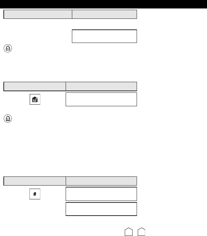
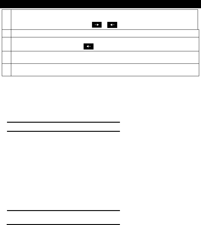
Chime ON/OFF
Disable / enable the chime zones by alternate clicking of the key, as shown below:
PRESS RESULTING DISPLAY
CHIME ON
CHIME OFF
HH:MM READY
CHIME indicator lights steadily on the KP-250 PG2 keypad, when “chime on” is selected.
3. Arming and Disarming the System
12 D-304269 KP-250 PG2 User’s Guide
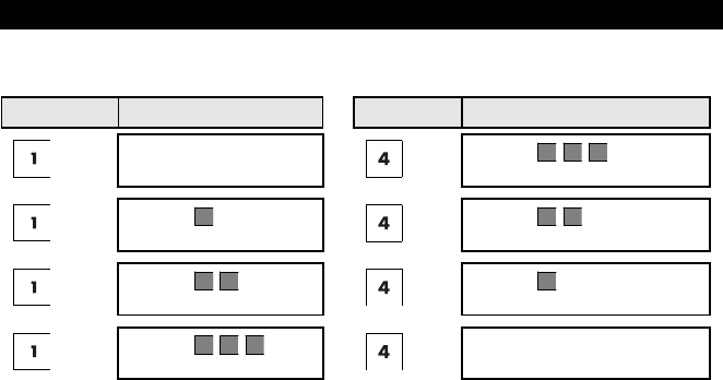
Adjusting the Volume of the Keypad Beeps
The following diagrams show how to increase or decrease the loudness by clicking the <1> or<4> key on the KP-250
PG2 keypad (assuming that the volume was at minimum/maximum to begin with).
PRESS RESULTING DISPLAY PRESS RESULTING DISPLAY
VOLUME+
(max)
VOLUME
VOLUME+
VOLUME
VOLUME+
VOLUME
(max)
VOLUME+
VOLUME
4. System Status and Indications
D-304269 KP-250 PG2 User’s Guide 13
4. System Status and Indications
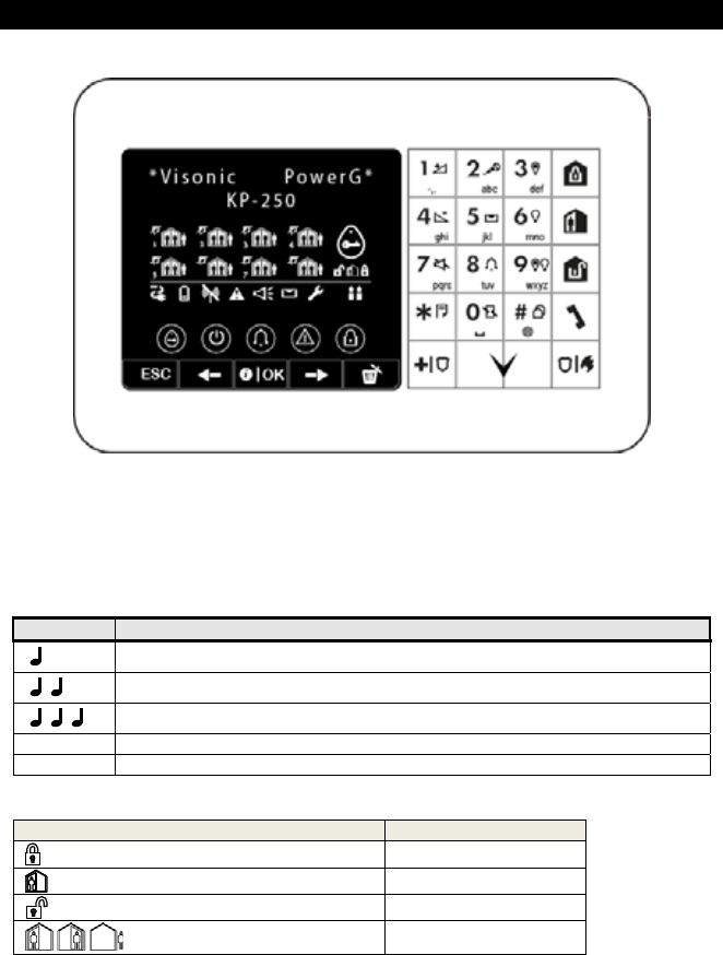
Note: The icons and numbers shown on the above keypad drawing are for illustrative purposes only.
When executing a command, the KP-250 PG2 keypad's LED blinks red once to indicate transmission of the command
to the control panel. If the operation is successfully completed, the green LED lights momentarily and a "happy tune"
sounds. If the operation fails or cannot be completed, for example, when the system is "Not Ready", the red LED
lights steadily and a "sad tune" sounds.
LCD Display and General Audible Indicators
The display is in two lines and is used to display system status and events, time and date, programming instructions and
also an event log file
The sounds you will hear while using the system are:
Sound Definition
Single beep, heard whenever a key is pressed
Double beep, indicates automatic return to the normal operating mode (by timeout).
Three beeps, indicates a trouble event
♫ Happy Tune (- - - –––), indicates successful completion of an operation.
♫ Sad Tune (–––––), indicates a wrong move or rejection
Arming Indications
The table below lists the Arming indication keys and their definition.
Icon/Key Indications Arming Indication
ARM AWAY
ARM HOME
DISARM
The icons appear consecutively EXIT DELAY
4. System Status and Indications
14 D-304269 KP-250 PG2 User’s Guide
General Indications
The Ready/Not Ready, Alarm Memory, Trouble and Low Battery indications are provided via the indications in the
following table:
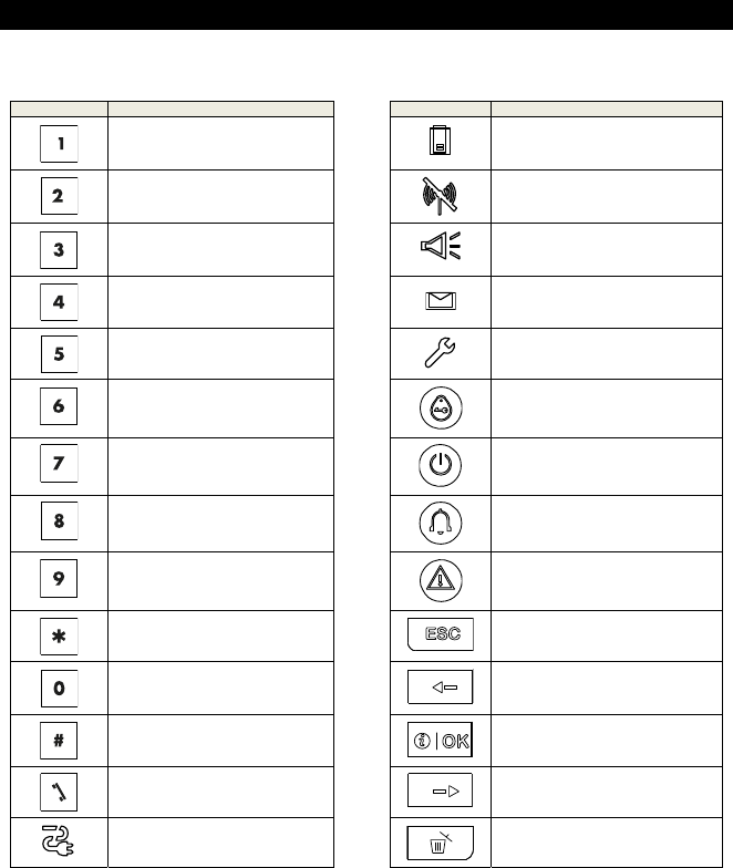
Indication What it Means Indication What it Means
KP-250 PG2 Volume up KP-250 PG2 low battery.
Record a message
Communication failure: KP-250 PG2
is out of range of panel
PGM on Memory / Alarm in partition or system
KP-250 PG2 Volume down A message is waiting in the control
panel
Play a message
The system is in INSTALLER MODE
or USER SETTINGS
PGM off
Instructs the user to present the
proximity tag (at the position of this
indication).
PowerMaster Mute speaker
AC ON
Chime ON / OFF
Keypad Chime ON / OFF status
PGM control
System Trouble
Event log / enroll button
Escape
Instant
Previous
Partition selection
Info. / OK
Dialer to call telephone numbers (for
future use)
Next
AC failure
Discard / abort

4. System Status and Indications
D-304269 KP-250 PG2 User’s Guide 15
Alarm Indication Siren
The PowerMaster system incorporates one or more high power sirens that sound in case of alarm. A siren can sound
from either the control panel or from a device and may be a part of a system component.
Alarm Type Graphic Representation of Signal Verbal Description of Signal
Burglar / 24
hour/ Panic ––––––––––––––––––––––––––––––– ON continuously
Fire – – – – – – – – – – – – ................. ON - ON - ON - pause - ON - ON - ON - pause.....
Flood – – – ................. ON - pause - ON - pause - ON - pause.....
Gas – – – – – – – – – – – – – – – – ........ ON - ON - ON - ON - pause - ON - ON - ON - ON -
pause.....
Test* –– (both external siren and internal sounder) ON for 2 seconds (once)
* Not included in all models
5. Reviewing Troubles and Alarm Memory
16 D-304269 KP-250 PG2 User’s Guide
5. Reviewing Troubles and Alarm Memory
Alarm & Tamper Memory Indication
The KP-250 PG2 retains in its memory alarm and “tamper” events that occurred during the last arming period.
Note: Alarm events are memorized only after the “abort period”. This means that if you disarm the system immediately -
before the abort period expires - there will be no memory indication
A. Indication of Alarm & Tamper Condition
If the system is disarmed following an alarm event, a flashing MEMORY message will be displayed, as follows:
HH:MM READY
MEMORY
B. Displaying Alarm & Tamper Information
To review memory content, click button.
EXAMPLE: An alarm was triggered because the garage door - zone No. 12 – was opened but then closed. In addition,
the bedroom motion detector - zone No. 7 - sent a “Tamper” message because its cover had been removed.
PRESS RESULTING DISPLAY PRESS RESULTING DISPLAY
KP-250
V 1.0.07 Bedroom
Z07 TAMPER OPEN
(alternating)
Garage door
Z12 ALARMED
Z06 Motion sens
Z07 TAMPER OPEN
(alternating)
Z03 contact
Z12 ALARMED
In response to additional clicking of the button, the display shows details of other events retained in open tamper
(if any), or reverts to its initial state (see A above).
If the system is NOT READY, the display will first read the open zones and then alarm memory events.
Clearing the Memory Indication
To clear the ‘Memory’ indication you must first review the cause of alarm as described above. Once you return to the
‘Ready’ screen simply press Away and enter the code if requested, then press Disarm followed by the code.
The memory message will now clear. Otherwise the memory indication and content will be cleared upon the next arming
of the system.
Troubles
A. Indication of Trouble condition
If the system detected a trouble condition in any of the enrolled devices, the TROUBLE indicator illuminates, 3 beeps
are sounded once per minute and a flashing TRBL message is displayed, as follows.
HH:MM READY
TROUBLE
HH:MM NOT READY
TROUBLE
or, if the system is not ready for
arming
5. Reviewing Troubles and Alarm Memory
D-304269 KP-250 PG2 User’s Guide 17
B. Displaying Trouble Information
All trouble messages need to be reviewed and corrected as described below:
EXAMPLE: The kitchen device - zone No. 9 - has reported a low battery – the living room device zone No. 15 - has
been inactive, and an attempt to communicate a message to your telephone has failed. However, these troubles do not
prevent the system from being “ready to arm”.
To review the source of the current troubles one by one, click the button repeatedly as shown below:
PRESS RESULTING DISPLAY PRESS RESULTING DISPLAY
KP-250
V 1.0.07 Living room
Z15 MISSING
(alternating)
Kitchen
Z09 LOW BATTERY
Z15 Motion sens
Z15 MISSING
(alternating)
Z09 Contact
Z09 LOW BATTERY
IMPORTANT! If the trouble beeps bother you, disarm the system again (even though it is already disarmed). This will
cancel the trouble beeps for 4 hours.
C. Reviewing Memory & Troubles at the Same Time
If alarms / tamper events are retained in the alarm memory and at the same time a state of trouble exists, the display
will first read the alarm memory followed by trouble events, as described in sections A & B above.
GSM/GPRS Status Indications
After all trouble messages have been reviewed and if a SIM card is installed in the panel, the KP-250 PG2 displays the
GSM signal strength indication, as follows: "GSM RSSI STRONG" / "GSM RSSI GOOD" / "GSM RSSI POOR".
If a PIR camera is enrolled in the system, the control panel will read "GPRS initialize" to indicate that the modem is
undergoing initialization. This message appears at the end of all trouble messages and immediately following the GSM
signal strength indication (if a SIM card is installed).

5. Reviewing Troubles and Alarm Memory
18 D-304269 KP-250 PG2 User’s Guide
Trouble Indications
The trouble indications (illuminated TROUBLE indicator and flashing TRBL message) are cleared once you eliminate
the cause of trouble.
Fault What it means
1-WAY The device functions but cannot "hear" the panel. The control panel cannot configure
or control the device. Battery consumption increases.
AC FAILURE There is no power supplied to the device.
FIRE CLEAN The fire detector must be cleaned
COMM. FAILURE A message could not be sent to the monitoring station or to a private telephone (or a
message was sent but was not acknowledged)
CPU LOW BATTERY The backup battery within the control panel is weak and must be replaced (see
PowerMaster-10/30 G2 Installer’s Guide, section 7.3, or, PowerMaster-33 G2
Installer’s Guide, section 5.2).
CPU TAMPER OPEN The control panel was physically tampered with or its cover was opened, or it was
removed from wall.
GAS TROUBLE Gas detector failure
GAS NET FAIL The GSM communicator is not able to connect to the cellular network.
SYSTEM JAMM A radio-frequency signal which is blocking all communication frequency channels
between the sensors and control panel is detected.
LINE FAILURE There is a problem with the telephone line
LOW BATTERY The battery of the indicated device is near the end of its useful life.
MISSING A device or detector has not reported for some time to the control panel.
NOT NETWORKED A device was not installed or not installed correctly, or, cannot establish
communication with the control panel after installation.
RSSI LOW The GSM communicator has detected that GSM network signal is weak
SIREN AC FAILURE There is no power to the siren
TAMPER FAILURE The sensor has an open tamper
TROUBLE The sensor reports trouble
SOAK TEST FAIL Detector alarms when is Soak Test mode
6. System Configuration
D-304269 KP-250 PG2 User’s Guide 19
6. System Configuration
This chapter explains the user programming features of your PowerMaster system using the KP-250 PG2 keypad.
To access the User Settings menus, a KP-250 PG2 keypad must first be enrolled in the system. For instructions on how
to enroll the KP-250 PG2 Keypad, refer to the KP-250 PG2 Installer’s Guide, section 11.4.
The Master User has access to all the User Settings menus, while the User has access only to the bypass menus (see
section B.4 in this chapter, which describes in detail the concept of User and Master User codes).
A.1 Entering the User Settings Menu & Selecting a Setting Option
The following procedure describes how to enter and move within the User Settings menu.
Detailed descriptions of the User Settings options are provided at the end of the procedure.
To exit the User Settings menu – see section A.2.
1. You can enter the "USER SETTINGS" menu only when the system is disarmed.
2. Carefully read the section titled "Additional Information" according to the indicated references 1 etc – see table
at end of this section.
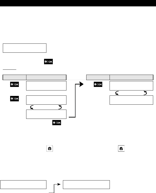
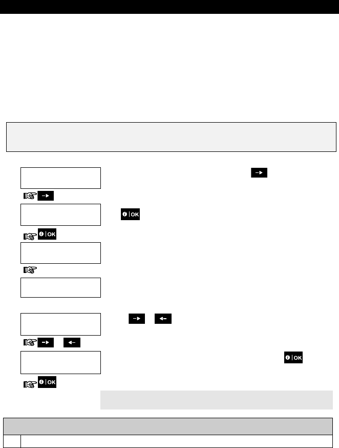
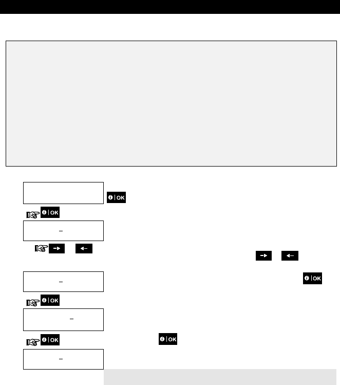
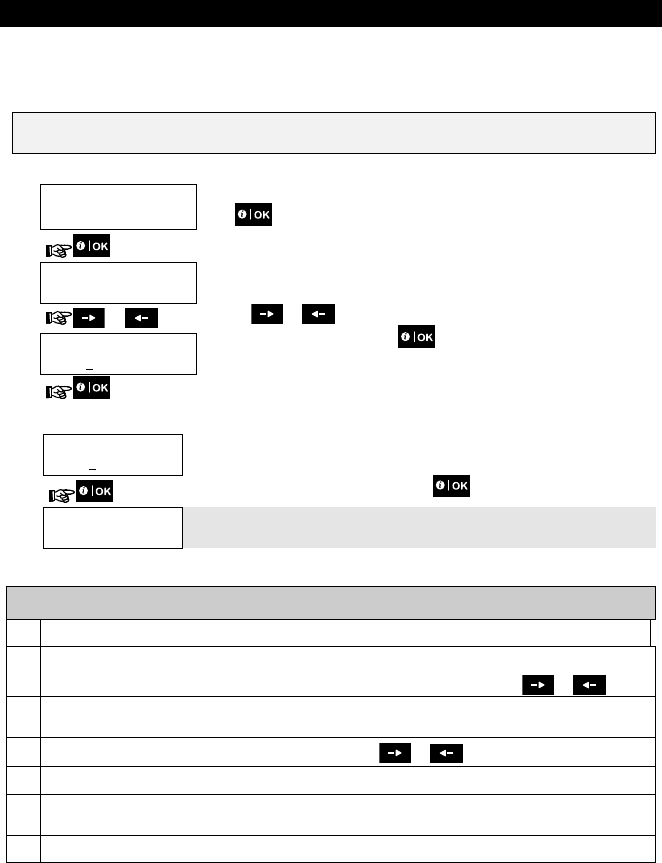
A. To Enter the USER SETTINGS Menu
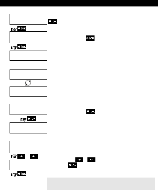
1. HH:MM READY
Make sure the system is disarmed and then press the button repeatedly on
the KP-250 PG2 until the display reads [USER SETTINGS]. 1
2. USER
SETTINGS Press
PRESENT TAG OR
ENTER CODE:
The screen will now prompt you to enter your user code or present your proximity
tag.
3. CODE Enter your User Code. 2
SET ZONE BYPASS The display reads the first Setting option of the User Settings menu [SET ZONE
BYPASS]. 3
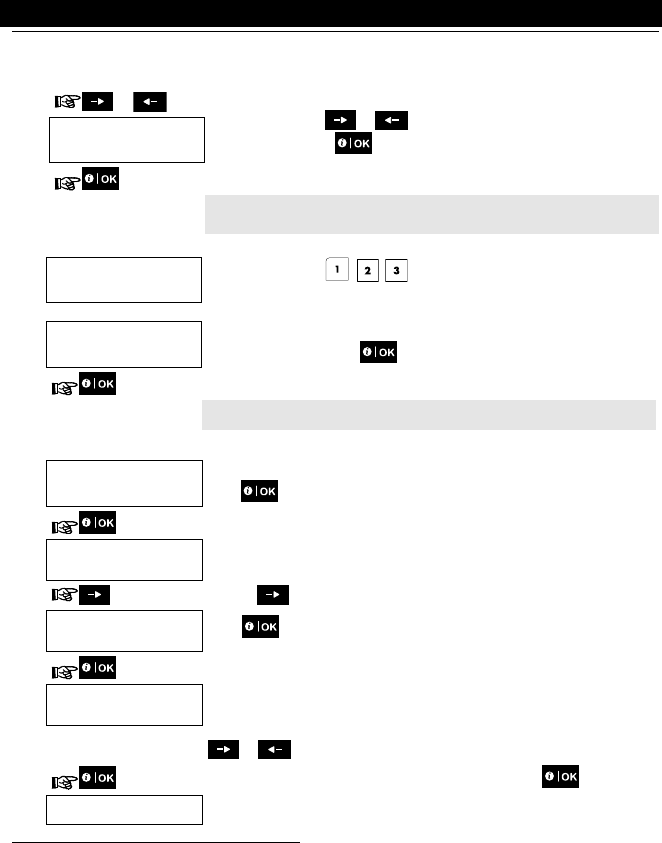
B. To Select a Setting Option
4. SET ZONE BYPASS Click the or button until the display reads the desired setting option,
for example, "TIME & FORMAT".
or
5. TIME & FORMAT
When the desired setting option appears on the display, press the button to
enter the setting process.
Continue to the selected
setting option in B.1 - B.16
The remainder of the procedures for the selected setting options is provided in
sections B.1 to B.16.
Additional Information (section A.1)
1
Display shown in disarm state when all zones are secured (00:00 or other digits show present time).
6. System Configuration
20 D-304269 KP-250 PG2 User’s Guide
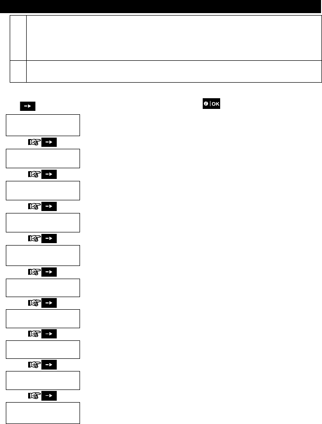
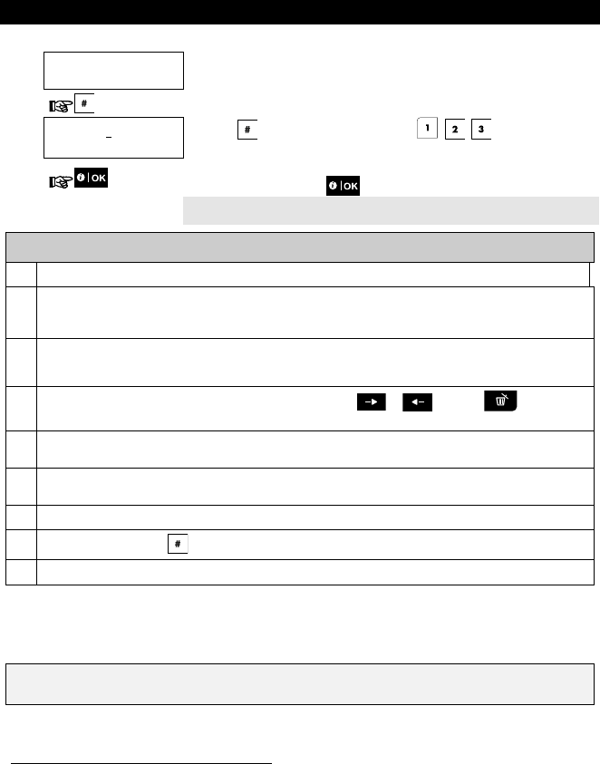
C. User Settings Options Menu
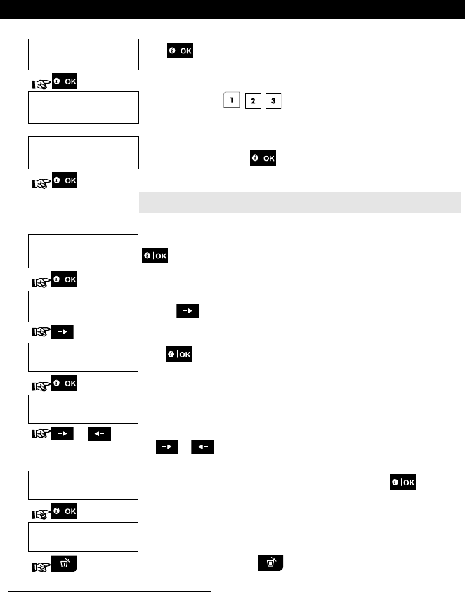
Click until the display reads the desired setting option and then press .
SET ZONE BYPASS
Use to set the Zone Bypass Scheme i.e. to bypass (exclude) faulty or unsecured
("disturbed") zones, or to clear a bypassed zone (unbypass). For further details and
programming procedure see section B.1.
REVIEW BYPASS
Use to quickly review the Bypass Scheme i.e. which zones are bypassed. For further
details and reviewing procedure see section B.2.
RECALL BYPASS
Use to Recall the last used bypassed scheme for reuse in next arming period. For further
details and recalling procedure see section B.3.
USER CODES
Use to program your Master User secret access code and the seven codes of the other
users. For further details and programming procedure see section B.4.
DURESS ALARM
CODE 2580
Use to send a duress (ambush) alarm message to the Monitoring Station if you are
forced to disarm the system under violence or menace. For further details and
programming procedure see section B.5.
PROXIMITY TAGS
Use to add new Proximity Tags to or to delete Proximity Tags when lost. For further
details and programming procedure see section B.6.
KEYFOBS
Use to add new Keyfob Transmitters or to delete Keyfob Transmitters when lost. For
further details and programming procedure see section B.7.
TIME & FORMAT
Use to set the time clock to show the correct time and time format. For further details and
programming procedure see section B.8.
DATE & FORMAT
Use to set the calendar date to show the correct date and date format. For further details
and programming procedure see section B.9.
AUTO-ARM
disable
Use to enable or disable the Automatic Daily Arming option at predefined times (see
Auto-Arm Time setting). For further details and programming procedure see section
B.10.
2
a. If you have not already changed your personal code number, use the default setting – 1111.
b. Master User has access to all User Settings options. Other users have access only to the Bypass options.
c. If you enter an invalid user code 5 times, the keypad will be automatically disabled for a pre-defined period
of time and the message WRONG PASSWORD will be displayed.
3
The bypass options will be displayed in the User Settings menu only if enabled by the installer. Otherwise, the
first User Settings option displayed will be [
USER CODES
].
6. System Configuration
D-304269 KP-250 PG2 User’s Guide 21
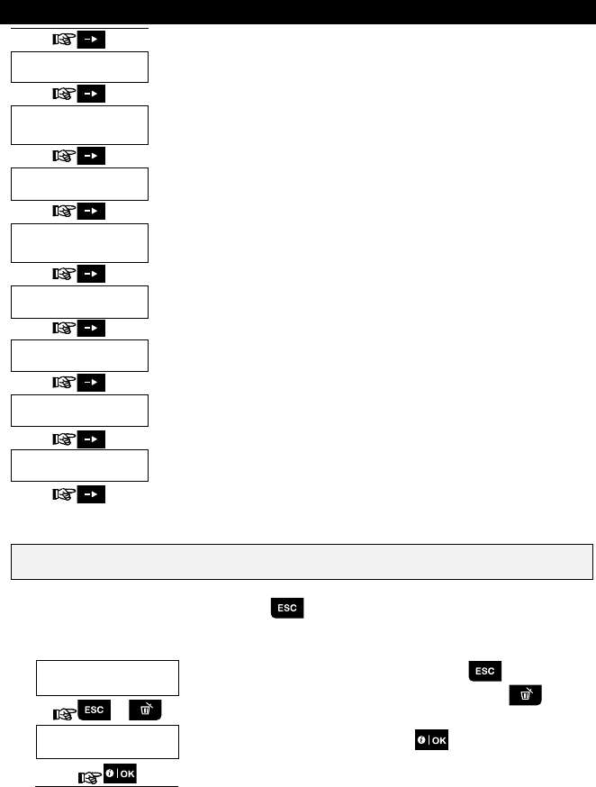
AUTO-ARM TIME
12:00P
Use to set the predetermined time for the Automatic Daily Arming if enabled (see Auto-
Arm Enable setting). For further details and programming procedure see section B.11.
PRIVATE REPORT
Use to program the four private telephone numbers for reporting alarm and other event
messages to private subscribers. For further details and programming procedure see
section B.12.
SQUAWK
on Use to enable or disable the squawk sound i.e. arm / disarm feedback indication. For
further details and programming procedure see section B.13.
SCHEDULER Use to set the daily / weekly time schedule for start & stop activation of devices
connected to the PGM output. For further details and programming procedure see
section B.14.
VOICE OPTION
disable Use to enable or disable the voice option i.e. the voice prompts that are heard over the
external voice box. For further details and programming procedure see section B.15.
PANEL VOLUME
Use to adjust the volume of the panel’s speaker or external voice box. For further details
and programming procedure see section B.16.
SERIAL NUMBER
Use to read the system serial number and similar data. For further details see section
B.17.
<OK> TO EXIT
Use to exit from the “USER SETTINGS” menu back to Main Menu. For further details
see section A.2.
Returns to first option
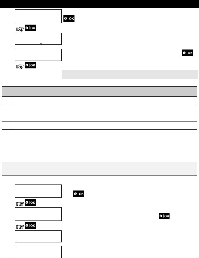
A.2 Returning to the Previous Step or Exiting the USER SETTINGS Menu
During the setting process it is frequently necessary to return to the previous setting step or option (i.e. "to go one level
up") or to exit the User Settings menu.
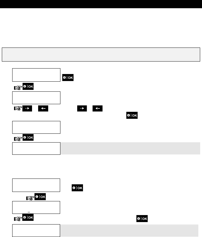
1. To Move One Level Up
To move one level up during the setting process, click once or more. Each click will take you one level up or to
the previous setting step.
2. To Exit the USER SETTINGS Menu
1. Any
screen To exit [USER SETTINGS], move up the menu by pressing repeatedly (see
above) until the display reads [<OK> TO EXIT], or preferably, press once
which brings you immediately to the exit screen [<OK> TO EXIT].
2. or
<OK> TO EXIT
When the display reads [<OK> TO EXIT], press
3.
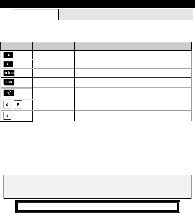
6. System Configuration
22 D-304269 KP-250 PG2 User’s Guide
12:00 READY
The system exits the [USER SETTINGS] menu and returns to the normal disarm
state while showing the READY display.
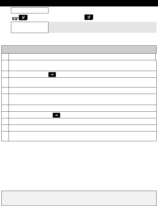
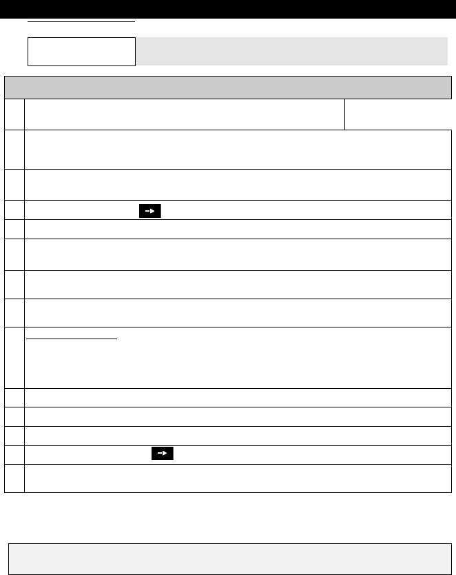
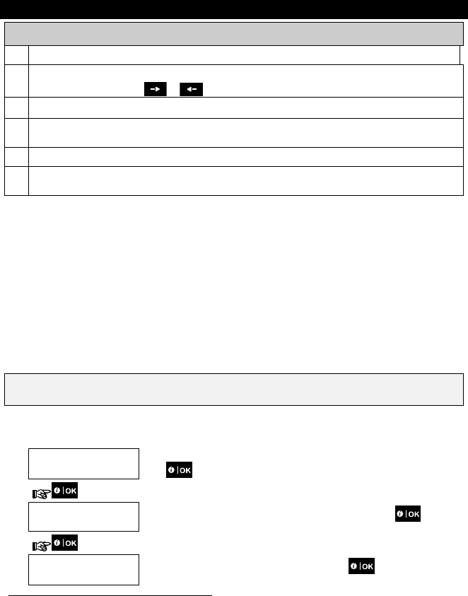
A.3 Buttons used for Navigation & Setting
The keypad's buttons are used for various functions when programming. The following table provides a detailed
description of the function or use of each button.
Button Definition Navigation / Setting Function
NEXT Use to move / scroll forward to the next menu options.
BACK Use to move / scroll backward to the previous menu options.
OK Use to select a menu option or to confirm a setting or action.
Escape Use to move one level up in the menu or to return to previous
setting step.
Delete / abort Use to edit a field or jump back to the [<OK> TO EXIT] screen to quit
programming.
- Numerical keypad used to enter numerical data.
Partition selection Use to change the status of partitions when programming user codes
B.1 Setting the Zone Bypass Scheme
Bypassing permits arming only part of the system and at the same time allowing free movement of people within certain
zones when the system is armed. It is also used to temporarily remove from service faulty zones that require repair work
or to deactivate a sensor if, for example, you are decorating a room.
Here you can set the Zone Bypass Scheme i.e. to scroll through the list of registered (enrolled) sensors to your
PowerMaster system and to Bypass (deactivate) faulty or disturbed sensors (either READY or NOT-READY) or to
Clear (reactivate) BYPASSED zones (sensors).
Once you have set a Bypass Scheme you can use the following 3 options:
> To quickly review the bypassed zones – refer to section B.2.
> To quickly clear a bypassed zone i.e. to reactivate the bypassed zone – refer to section B.1.
> To repeat (recall) the last used zone bypassing scheme – refer to section B.3.
1. Zones will be bypassed throughout one disarm-arm period only. Disarming the system after arming will
suspend the entire bypassing scheme but you can recall and reuse it as described in section B.3.
2. Fire zones cannot be bypassed.
3. Carefully read the section titled "Additional Information" according to the indicated references 1 etc – see
table at end of section B.3.
REMEMBER – ZONE BYPASSING COMPROMISES SECURITY!
6. System Configuration
D-304269 KP-250 PG2 User’s Guide 23
A. To Bypass a Zone
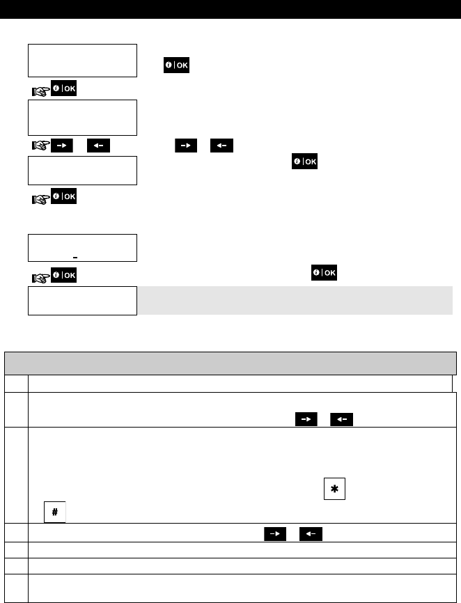
1. SET ZONE BYPASS
Enter the [USER SETTINGS] menu1, select the [SET ZONE BYPASS] 2 option and
press .
Z01: READY
Living Room
The first zone, Z01, is displayed. 3
Z01: P1 P2 P3
4
2. or Click the or button until the display reads the zone you wish to
bypass (or clear bypass), for example, "Z04" for Zone 04. After several seconds
the LEDs on the respective device starts flashing indicating "it's me".
Z04: NOT READY
Z04: P1 P2 P3
3. Kitchen
When the display reads the zone you wish to bypass press .
4. <OK> TO BYPASS
The display now reads [<OK> TO BYPASS].
5
To bypass the selected zone press
Z04:BYPASSED
A "Happy Tune"
☺ sounds and the updated zone status is now displayed i.e.
[
Z04: BYPASSED
]. 8
B. To Clear a Bypassed Zone
5. Z04: BYPASSED
Z04: P1 P2 P3
Repeat steps 1 to 2 above.
4
6. Kitchen
When the zone you wish to clear bypass appears on the display (for example,
"Z04"), press to confirm. You can also identify the device by looking for the
"it's me" LED indication on the displayed device.
<OFF> TO CLEAR
The display now reads [<OFF> TO CLEAR]. 5
7.
To clear the bypassed zone, press the button.
Z04:READY
A "Happy Tune"
☺ sounds and the updated zone status is now displayed, i.e.
[
Z04: READY
] or [
Z04: NOT READY
]. 9
6. System Configuration
24 D-304269 KP-250 PG2 User’s Guide
B.2 Reviewing the Zone Bypass Scheme
Here you can quickly review the Bypass Scheme i.e. the zones that are set to be bypassed during the next arming
session.
1. REVIEW BYPASS Enter the [USER SETTINGS] menu and select the [REVIEW BYPASS]1 option and
press . 2
2. BYPASS LIST
The display reads [BYPASS LIST]
or Click the or buttons repeatedly to review all bypassed zones in
ascending numerical order. When done, click to exit. 9
3. Z04: BYPASSED
Z04: P1 P2 P3
Kitchen
B.3 Recalling the Zone Bypass Scheme
Use this option to repeat (recall) the most recent Bypassed Scheme for use during the next arming session.
1. RECALL BYPASS
Enter the [USER SETTINGS] menu, select the [RECALL BYPASS] 1 option and
press . 2, 6
2. <OK> TO RECALL
The display now reads [<OK> TO RECALL].
7
To recall the last used bypass scheme press .
BYPASS RECALLED
A "Happy Tune" ☺ sounds. The display reads [
BYPASS RECALLED
] and then
returns to “
USER SETTINGS
" step 1. 9
☺ Return to step 1
Additional Information (section B.1 – B.3)
1
For detailed instructions on how to select User Settings – refer to section A.1 and section A.2.
2
This menu is displayed only if "BYPASS" was previously enabled by the installer.
3
The STATUS to the right of the zone number indicates whether the zone is READY, NOT-READY or
BYPASSED.
4
This display will appear only if PARTITIONING was previously enabled.
6. System Configuration
D-304269 KP-250 PG2 User’s Guide 25
5 a. If the zone you selected is "not bypassed", the display prompts you to press [
<OK> TO BYPASS
]. However, if
the zone you selected is already "bypassed", the display prompts you to press [
<OFF> TO CLEAR
].
b. To abort and return to the previous step press or
6
This menu is not displayed if Partition is enabled.
7 The display now prompts you to press [
<OK> TO RECALL
] i.e. to repeat the last used bypass scheme. To abort
and return to the User Settings menu, press .
8 You can now repeat steps 2 - 4 to bypass or clear another zone. To end this session and to select other menu
options or to quit programming - follow the instructions in section A.2.
9 You can now select another option in the User Settings menu (see section A.1), or quit programming (see section
A.2).
B.4 Programming User Codes
PowerMaster system allows you to authorize up to 8 (PowerMaster-10 G2) / 48 (PowerMaster-30 G2 / PowerMaster-33
G2) people to arm and disarm the system by providing each with a unique 4 digit personal security code (code 0000 is
not allowed), and assigning them with different security levels and functionalities. Moreover, you can obtain up to 8
(PowerMaster-10 G2) / 32 (PowerMaster-30 G2 / PowerMaster-33 G2) multi-function portable keyfob transmitters that
will allow you and the other users to easily arm, disarm and control the system without accessing the KP-250 PG2 or
panel, including from outside the premises (see section B.7 Add / Delete Keyfob Transmitters). The Duress Code
enables you to disarm the system using a special code that sends a silent alarm to the monitoring station.
There are two types of users: Master User and User. The table below summarizes the different operations that can be
performed by different users:
User type Function
Master User Arm/disarm
Zone bypass
Authorize other user codes
Set user codes
Report to private
Enroll/delete proximity tag
Enroll/delete keyfob
Automatic arming
Enable squawk
Set date and time format
Read event log
Programming the duress code
Programming the scheduler
Enabling/disabling voice option
Adjusting volume
User Arm/disarm
Zone bypass options
The user codes are assigned as follows:
User Code 1 is assigned to the Master User of the system (i.e. the owner). It is the only user code that allows access to
the User Settings menu. The default setting of the Master User code is 1111. This code cannot be erased and must be
replaced with a secret code as soon as possible.
User Codes 2-4 (PowerMaster-10 G2) / User Codes 2-22 and 33-48 (PowerMaster-30 G2 / PowerMaster-33 G2) are
assigned to family members, co-workers etc. They enable arming and disarming of the system or of selected partitions
as defined by the Master User. They can access the "User Settings" menu only for "zone bypassing" provided this
option is enabled in the Installer menu.
6. System Configuration
26 D-304269 KP-250 PG2 User’s Guide
User Codes 5-8 (PowerMaster-10 G2) / User Codes 23-32 (PowerMaster-30 G2 / PowerMaster-33 G2) are the
same as user codes 2-4 (PowerMaster-10 G2) / 2-22 (PowerMaster-30 G2 / PowerMaster-33 G2) but can be assigned
to "Latchkey" (child monitor) users. For a detailed explanation of the Latchkey application see Chapter 3.
A. To Program a User Code
Partition Option (For information about Partition option - see APPENDIX B)
Your alarm system can divide zones into up to 3 parts (groups) via the installer menu. These parts are
designated as partitions P1, P2 & P3. Each partition can be armed and disarmed separately, providing protection
to selected parts of the premises.
Each user out of the 8 (PowerMaster-10 G2) / 48 (PowerMaster-30 G2 / PowerMaster-33 G2) system users can
be authorized by the Master User to arm and disarm any combination of partitions including all 3 partitions.
Here you can program (or edit) the 8 (PowerMaster-10 G2) / 48 (PowerMaster-30 G2 / PowerMaster-33 G2)
User Codes and thereby define which of these will be authorized to arm and disarm.
1. The default setting 1111 of the Master User Code is the same for all PowerMaster systems and is known to
many other people. Therefore, we highly recommend that you immediately replace it with a unique secret
code.
2. Code "0000" is not valid! Do not use it.
3. The duress code (2580 by default), which is set in the installer menu, cannot be selected as a normal user
code. Any attempt to program it will be rejected by the system.
4. Carefully read the section titled "Additional Information" according to the indicated references 1 etc – see
table at end of this section.
1. USER CODES
Enter the [USER SETTINGS] menu, select the [USER CODES] option and press
. 1
2. User 01: 1111
The first user code "User 01: 1111" is displayed. 2
or At the blinking cursor position, key in the User Code you wish to program , for
example, [06] for user code 6, or alternatively click the or button until
the display reads, [User 06: 0000].
3. User 06: 0000
When the user code you wish to program appears on the display, press .
4. User 06: 0000
To program or edit the code, at the blinking cursor position enter the 4 digit code,
for example, “1234”, using the numerical keypad. 3, 4
5. When done, press .
User 06: 1234
☺ Return to step 3 A "Happy Tune" ☺ sounds. The display confirms the saved code. 5, 6
6. System Configuration
D-304269 KP-250 PG2 User’s Guide 27
B. To Set Partitions Authorization
Additional Information (section B.4)
1 For detailed instructions on how to select the setting options – refer to section A.1 and section A.2.
2 The display shows the 1st User Code (Master User) in the list of 8 (PowerMaster-10 G2) / 48 (PowerMaster-30
G2 / PowerMaster-33 G2) User Codes. If you have not yet changed the default code 1111, we recommend that
you change it now.
3 a. The display shows the user code currently programmed in this location (e.g. 5327).
b. The cursor blinks on the first digit of the code.
c. If the location is free the display will be (0000).
4 You can move the cursor to the next or previous digit by pressing or . Pressing erases the
digit of the cursor + all digits to the right of the cursor.
5 a. The new code is momentarily displayed without the cursor before reverting to step 3.
b. If Partition is enabled, continue to step 6.
6 You can now repeat steps 3 - 5 to program or edit another user code. To end this session and to select other
menu options or to quit programming – follow the instructions in section A.2.
7 This setting can be performed only after completing steps 1 - 5 of section B.4A.
8
At this stage, pressing the button continuously switches between the first and second rows.
9 You can now repeat steps 3 - 7 to program or edit another user code.
B.5 Programming the Duress Code
A duress (ambush) alarm message can be sent to the Monitoring Station if you are forced to disarm the system under
violence or menace. To initiate a duress message, you must disarm the system using a duress code (2580 by default)
Here you program the duress code.
Carefully read the section titled "Additional Information" according to the indicated references1 etc – see table at
end of this section.
Refers to when PARTITIONING is enabled.
6. User 06: 1234
1 2 3 The display will now enable you to set the partitions. 7
7. User 06: 1234
1 2 3 Press the button and use the keypad keys , , to change the status
of the partitions 1, 2 & 3, respectively. 8
When you are satisfied with the setting, for example, User 6 is authorized with
Partition 1 and 3 only, press to confirm.
☺ Return to step 3 A "Happy Tune" ☺ sounds. The display confirms the Partition setting. 9
6. System Configuration
28 D-304269 KP-250 PG2 User’s Guide
1. DURESS
CODE 2580
Enter the [USER SETTINGS] menu, select the [DURESS CODE] option and press
. 1
2. DURESS
CODE 2580
At the blinking cursor position, key in the Duress Code you wish to program, for
example, 6973. 2, 3
DURESS
CODE 6973 When the duress code you wish to program appears on the display, press .
3.
☺ Return to step 1 A "Happy Tune" ☺ sounds and The display confirms the saved setting. 4
Additional Information (section B.5)
1 For detailed instructions on how to select User Settings – refer to section A.1 and section A.2.
2 The display shows the default duress code (2580).
3 Do not set the duress code the same as an installer or user code.
4 You can now select another option in the User Settings menu or quit programming (see sections A.1 and A.2).
B.6 Add / Delete Proximity Tags
Users of the alarm system may be provided with a proximity tag/s that can be used instead of the user codes to perform
a variety of functions, for example, arming, disarming, reading the event log, etc.
Whenever a user code is required you can simply present a valid proximity tag instead of entering the user code.
Here you can add (enroll) new proximity tags or delete tags as required.
Carefully read the section titled "Additional Information" according to the indicated references1 etc – see table at
end of this section.
A. To Add (Enroll) a Proximity Tag
1. TAGS (Proximity)
Enter the [USER SETTINGS] menu, select the [TAGS (Proximity)] option and
press .
1
2. ADD NEW
TAG
The display will read [ADD NEW TAG]. 3
To begin the process of enrolling a new proximity tag press .
3. ENROLL NOW or
ENTR ID:xxx-xxxx Present the proximity tag to the KP-250 PG2 within the timeout period.
4. DEVICE ENROLLED
T01:Tag (Prox)
If enrollment was successfully completed, a "Happy Tune" ☺ sounds and the
display reads [DEVICE ENROLLED] for a short duration and then changes to read
6. System Configuration
D-304269 KP-250 PG2 User’s Guide 29
☺ Go to step 5 the tag's details. 4
The display shows the allocated tag serial No (user No.), which is always the first
free number, for example: [T01:Tag (Prox)].
5. or To assign the tag to another user, for example, "User No. 5", key in [05] or
alternatively click the or button until the display reads [T05:Tag
(Prox)] and then press to confirm.
DEVICE ENROLLED
T05:Tag (Prox)
☺ Return to step 2 The display reads [
DEVICE ENROLLED
] a "Happy Tune" ☺ sounds and the
display will then change to [
T01:Tag (Prox)
]. 5 6
B. To Set Partitions Authorization
C. To Delete a Proximity Tag
1. TAGS (Proximity)
Enter the [USER SETTINGS] menu, select the [TAGS (Proximity)] option and
press . 1
2. ADD NEW
TAG
The display will read [ADD NEW TAG].
Click the button until the display reads [DELETE TAG].
3. DELETE
TAG Press .
T01:Tag (Prox)
The display will read [T01:Tag (prox)]. 2, 7
4. Key in the tag number you wish to delete, for example, [05] or alternatively click the
or button until the display reads the tag number, [T05:Tag (prox)].
5. When the tag you wish to delete appears on the display, press .
<DEL> to delete The display now reads [<DEL> to delete]. 8
Refers to when PARTITIONING is enabled.
6. T05:PARTITIONS
1 2 3 Use the keypad keys , , to change the status of the partitions 1, 2 &
3, respectively. 9
7. T05:PARTITIONS
1 2 3
When you are satisfied with the setting, for example, User 5 is authorized with
Partition 1 and 3 only, press to confirm.
☺ Return to step 2 A "Happy Tune" ☺ sounds. The display confirms the Partition setting. 10
6. System Configuration
30 D-304269 KP-250 PG2 User’s Guide
6. To delete the tag press the button.
DELETE
TAG
A "Happy Tune" ☺ sounds and the display reads [
DELETE TAG
] and returns to
step 3. 11
☺ Go to step 3
Additional Information (section B.6)
1 For detailed instructions on how to select User Settings – refer to section A.1 and section A.2.
2 The display shows the first enrolled Tag (Tag No.1) of the 8 (PowerMaster-10 G2) / 32 (PowerMaster-30 G2 /
PowerMaster-33 G2) tags.
3 To abort enrollment, press the button.
4 If the tag was previously enrolled in the system, the KP-250 PG2 display indicates this together with the tag's ID
number, for example, "ALREADY ENROLLED T01:Tag (Prox)".
5 If Partition is enabled, continue to step 6.
6 You can now enroll another proximity tag. You can also select another option in the User Settings menu (see
section A.1 and section A.2), or quit programming (see section A.3).
7 If no proximity tag is enrolled in the system, the display reads [
NO EXISTING DEV.
].
8 To abort the procedure, press the button.
9 This setting can be performed only after completing steps 1 - 5 of section B.6A.
10 You can now repeat steps 2 - 7 to program or edit another Proximity tag.
11 You can now add or delete another proximity tag. You can also select another option in the User Settings menu
(see section A.1 and section A.2), or quit programming (see section A.3).
B.7 Add / Delete Keyfob Transmitters
Each of the 8 (PowerMaster-10 G2) / 32 (PowerMaster-30 G2 / PowerMaster-33 G2) users may be provided with a
portable keyfob transmitter for better, quicker and safer arming/disarming and other control functions. Each keyfob
should be assigned with a serial No. 1-8 (PowerMaster-10 G2) / 1-32 (PowerMaster-30 G2 / PowerMaster-33 G2) and
enrolled into the system correspondingly.
Partition Option (For information about Partition option - see APPENDIX B).
If the Partition option is enabled in the KP-250 PG2, each of the 8 (PowerMaster-10 G2) / 32 (PowerMaster-30 G2 /
PowerMaster-33 G2) keyfobs can be authorized by the Master User to arm and disarm any combination, or all 3
partitions, irrespective of the authorization of its corresponding user code.
Here you can add (enroll) the 8 (PowerMaster-10 G2) / 32 (PowerMaster-30 G2 / PowerMaster-33 G2) Keyfob
transmitters and define which of the 3 partitions each of the keyfob will be authorized to arm and disarm, or delete
keyfobs as required.
1. Before anything else, gather up all keyfob units you intend to enroll and make sure they all have batteries
installed and that they are active (the LED blinks upon pressing any of the buttons).
2. Carefully read the section titled "Additional Information" according to the indicated references1 etc – see table
at end of this section.
6. System Configuration
D-304269 KP-250 PG2 User’s Guide 31
A. To Add (Enroll) a Keyfob
1. KEYFOBS
Enter the [USER SETTINGS] menu, select the [KEYFOBS] option and press
. 1
2. ADD NEW
KEYFOB
The display will read [ADD NEW KEYFOB]. 4
To enroll a new keyfob press .
3. ENROLL NOW or
ENTR ID:xxx-xxxx The display offers you two alternative methods to enroll a keyfob:
A: ENROLL NOW: Press and hold the AUX button on the selected keyfob until
the LED is constantly on. 2 This procedure completes the enrollment.
4a. DEVICE ENROLLED
ID No. 300-5786 If enrollment was successfully completed, a "Happy Tune" ☺ sounds and the
display reads [DEVICE ENROLLED] for a short duration and then changes to read
the keyfob's details. Continue to step 5.
DEVICE ENROLLED
F01:KEYFOB
☺ Go to step 5
4b. ID No. 300-5786
B: ENROLLMENT BY DEVICE ID: Enter the 7-digit number that appears on the
keyfob sticker and then press to confirm. To complete the enrollment
procedure, see Note 9 in the Additional Information table below.
ID ACCEPTED
If a valid ID was entered, a "Happy Tune" ☺ sounds and the display reads
[ID ACCEPTED] for a short duration and then changes to read the keyfob's details.
Continue to step 5.
☺ Go to step 5
5. F01:keyfob
ID No. 300-5786
The display shows the allocated keyfob serial No (user No.), which is always the
first free number, and the keyfob's ID number; for example:
[F01:Keyfob] alternating with [ID No. 300-5786].
or To assign the keyfob to another user, for example, "User No. 5", key in [05] or
alternatively click the or button until the display reads [F05:Keyfob]
and then press to confirm.
F05:keyfob
☺ Return to step 2 The display reads [
DEVICE ENROLLED
] or [
ID accepted
] if the keyfob was
enrolled manually by entering the ID number, a "Happy Tune" ☺ sounds and
the display will then change to [
F01:Keyfob
]. 5 6
6. System Configuration
32 D-304269 KP-250 PG2 User’s Guide
B. To Set Partitions Authorization
6. F05:PARTITIONS
Press to enter partitions mode.
7. F05:PARTITIONS
1 2 3 Use the keypad keys , , to change the status of the partitions 1, 2 & 3,
respectively. 10
8. F05:PARTITIONS
1 2 3
When you are satisfied with the setting, for example, User 5 is authorized with
Partition 2 and 3 only, press to confirm. 11
☺ Return to step 2 A "Happy Tune" ☺ sounds. The display confirms the Partition setting. 12
C. To Delete a Keyfob
1. KEYFOBS Enter the [USER SETTINGS] menu, select the [KEYFOBS] option and press
. 1
2. ADD NEW
KEYFOB
The display will read [ADD NEW KEYFOB].
Click the button until the display reads [DELETE KEYFOB].
3. DELETE
KEYFOB Press .
F01:Keyfob
ID No. 300-5786 The display will read [F01:Keyfob] and the ID number of the keyfob. 3
4. or Key in the keyfob number you wish to delete, for example, [06] or alternatively click
the or button until the display reads the keyfob number, for example,
"F06:Keyfob" and "ID No. 300-5799".
F06:Keyfob
ID No. 300-5799 When the keyfob you wish to delete appears on the display, press . 7
5.
<DEL> to Delete The display now reads [<DEL> to Delete]. 8
6. To delete the keyfob press the button. 13
Refers to when PARTITIONING is enabled.
6. System Configuration
D-304269 KP-250 PG2 User’s Guide 33
☺ Go to step 3
DELETE
KEYFOB A "Happy Tune" ☺ sounds and the display reads [
DELETE KEYFOB
] and
returns to step 3. 14
Additional Information (section B.7)
1 For detailed instructions on how to select User Settings – refer to section A.1 and
section A.2.
2 The LED will extinguish after several seconds. In case of difficulties in communication with the control panel, the
LED may blink for several seconds more while trying to establish communication. During this period of time the
keyfob keys are disabled.
3 The display shows the first enrolled Keyfob (Keyfob No.1) of the 8 (PowerMaster-10) / 32 (PowerMaster-30 G2 /
PowerMaster-33 G2) keyfobs.
4 To abort enrollment, press the button.
5 If Partition is enabled, continue to step 6.
6 You can now enroll another keyfob. You can also select another option in the User Settings menu (see section A.1
and section A.2), or quit programming (see section A.3).
7 If the keyfob was previously enrolled in the system, the KP-250 PG2 display indicates this together with the
keyfob's ID number, for example, "
ALREADY ENROLLED
F01:KEYFOBS".
8 Before you delete a keyfob, identify the keyfob either by the keyfob No., for example, F06, or by the ID number of
the keyfob that appears on the display, and then make sure that it is the keyfob you wish to delete.
9 Enrollment by Device ID:
Step 4b enables you to register the device ID and to complete the programming process without being in
possession of the device itself (can also be performed off-site by the installer). Enrollment can then be completed
at a later stage by following the same enrollment procedure described in Step 3 without entering the User Settings
menu.
10 This setting can be performed only after completing steps 1 - 5 of section B.7A.
11 The box symbol now appears next to the newly selected Partitions.
12 You can now repeat steps 2 - 8 to program or edit another keyfob.
13 To abort the procedure, press the button.
14 You can now add or delete another keyfob or select another option in the User Settings menu or quit
programming (see sections A.1 and section A.2).
B.8 Setting the Time & Time Format
Here you can program or adjust the built-in-clock to show the correct time in the desired time format.
You can select between a 24 hour and a 12 hour (AM/PM) time format.
Carefully read the section titled "Additional Information" according to the indicated references1 etc – see table
at end of this section.
6. System Configuration
34 D-304269 KP-250 PG2 User’s Guide
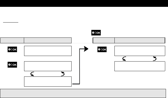
A. To Set the Time Format
1. TIME & FORMAT
Enter the [USER SETTINGS] menu and select the [TIME & FORMAT] option and
press . 1
2. EU FORMAT 24H
TIME: 19:22
The display shows the currently selected time format. 2
or Click the or button until the display shows the desired time format, for
example, "US FORMAT-24H" and press to confirm .
US FORMAT-12H
TIME: 03:15P
3.
B. To Set the Time 5
4. US FORMAT-12H
TIME: 03:15P At the blinking cursor position, enter the correct time, for example, “8:55A”, using
the numerical keypad. 3 4
5. When you are satisfied with the setting, press to confirm.
US FORMAT-12H
TIME: 08:55A A "Happy Tune" ☺ sounds, the display reads the set time, returns to step 1. 6, 7
☺ Return to step 1
Additional Information (section B.8)
1
For detailed instructions on how to select User Settings – refer to section A.1 and section A.2.
2
a. The display shows the currently selected format, for example, "
24 Hrs
".
b. You can now select either the 12 Hrs or 24 Hrs time format using the or buttons.
3
The display shows the Time in the selected Time Format, for example, "
12:40 PM
", with the cursor blinking on
the first hour digit "1". The letter that follows the displayed time indicates one of the following:
"A" = AM; "P" = PM and "none" for 24 Hrs time format.
When the curser is positioned on the AM/PM digit, you can set to "AM" with the button and the "PM" with
the button.
4
You can move the cursor to the next or previous digit using the or buttons.
5 This setting can be performed only after completing steps 1 – 3 of section B.8A.
6 The time saved is displayed without the cursor, for example, "
08:55 A
" followed by the selected time format.
7 You can now select another option in the User Settings menu (see section A.1 and section A.2), or quit
programming (see section A.3).
6. System Configuration
D-304269 KP-250 PG2 User’s Guide 35
B.9 Setting the Date & Date Format
Here you can program or adjust the built-in-calendar to show the correct date in the desired date format.
You can select between a "mm/dd/yyyy" and a "dd/mm/yyyy" date format.
Carefully read the section titled "Additional Information" according to the indicated references1 etc – see table
at end of this section.
A. To Set the Date Format
1. DATE & FORMAT
Enter the [USER SETTINGS] menu and select the [DATE & FORMAT] option and
press .
1
DATE DD/MM/YYYY
DATE: 01/01/2012
The display shows the currently selected date format. 2
2. or Click the or button until the display reads the desired date format, for
example, "DD/MM/YYYY" and press to confirm.
DATE DD/MM/YYYY
DATE: 01/01/2012
3.
B. To Set the Date 7
4. DATE DD/MM/YYYY
DATE: 20/04/2012
At the blinking cursor position, enter the correct date, for example, “20/04/2012”, using
the numerical keypad. 3, 4, 5
5. When you are satisfied with the setting, press to confirm.
DATE DD/MM/YYYY
DATE: 20/04/2012
A "Happy Tune" ☺ sounds, the display shows the set date and returns to step 1. 6
☺ Return to step 1
Additional Information (section B.9)
1 For detailed instructions on how to select User Settings – refer to section A.1 and section A.2.
2 The display shows the currently selected format, for example, "DD/MM/YYYY".
You can now select either the "MM/DD/YYYY" or "DD/MM/YYYY" date format by pressing or .
3 The display shows the Date and selected Date Format, for example, "
30.12.20
12", with the cursor blinking on the
first digit.
4 You can move the cursor to the next or previous digit using the or button.
5 For the year, enter the two last digits only.
6 You can now select another option in the User Settings menu (see section A.1 and section A.2), or quit
programming (see section A.3).
7 This setting can be performed only after completing steps 1 – 3 of section B.9A.
6. System Configuration
36 D-304269 KP-250 PG2 User’s Guide
B.10 Enabling / Disabling Auto-Arming
The PowerMaster system can be programmed to automatically arm itself on a daily basis at a predetermined time. This
feature is useful especially in commercial applications, such as in stores, to ensure that the system is always armed and
without having to assign security codes to employees.
Here you can enable (activate) and disable (stop) the Auto-Arming. To set the Auto-Arming time – see section B.11.
Auto-arming can arm a "NOT READY" system only if forced arming is enabled by the installer while programming
your system.
Carefully read the section titled "Additional Information" according to the indicated references1 etc – see table at
end of this section.
1. AUTO-ARM
enable
Enter the [USER SETTINGS] menu, select the [AUTO-ARM] option and press
. 1
AUTO-ARM
enable The display shows the currently selected setting. 2
2. or Click the or button until the display reads the desired setting, for
example, [disable autoarm] and press to confirm.
AUTO-ARM
disable
3.
AUTO-ARM
disable
A "Happy Tune" ☺ sounds. The display confirms the saved setting. 3
☺
B.11 Setting the Auto-Arming Time
Here you can program the exact time of the Auto-Arming.
1. AUTO-ARM TIME
12:00
Enter the [USER SETTINGS] menu, select the [AUTO-ARM TIME] option and
press . 1
2. AUTO-ARM TIME
12:00
The display shows the current setting of the Auto-Arm Time. At the blinking cursor
position, enter the correct time, for example, “8:30”, using the numerical keypad. 4
3. When you are satisfied with the setting, press to confirm.
AUTO-ARM TIME
08:30
A "Happy Tune" ☺ sounds. The display confirms the saved time, then returns to
the User Settings menu, step 1. 5, 6
☺ Return to step 1
6. System Configuration
D-304269 KP-250 PG2 User’s Guide 37
Additional Information (section B.10 - B.11)
1 For detailed instructions on how to select User Settings – refer to section A.1 and section A.2.
2 The display shows the current setting, for example, [AUTO-ARM
enable
]. You can now select either to enable or
disable auto-arming using the or button.
3 The symbol now appears next to the newly selected option.
4 The display shows the current setting of the Auto-Arm Time, for example, "
12:00 PM
", with the cursor blinking on
the first hour digit "1". For detailed explanation of how to set the time - refer to Section B.8B.
5 The saved auto arm time is displayed without the cursor, for example, "
08:30 A
".
6 You can now select another option in the User Settings menu (see section A.1 and section A.2), or quit
programming (see section A.3).
B.12 Programming Private Phone and SMS Reporting
The PowerMaster system can be programmed to send various event notification messages such as alarm, arming or
trouble events, to 4 private telephone subscribers by audible signal and, if a GSM option is installed, also to 4 SMS
telephone numbers. These reports can be programmed either instead of or in addition to the reports transmitted to the
monitoring company. Further details about the event notification by telephone and SMS are provided in the
PowerMaster-10/30 G2 User Guide, Chapter 7 Event Reporting and Control by Telephone and SMS.
You can also determine the number of times the private telephone number is dialed and whether a single acknowledge
signal will stop the reporting process or an acknowledge signal from each telephone will be required before the current
event is considered reported.
Here you can program:
The specific events you wish the system to report.
The 1st, 2nd, 3rd, and 4th private telephone and SMS numbers for reporting alarm and other event messages to
private subscribers.
The number of redial attempts, two-way voice communication, and whether to use a single acknowledge signal or
an acknowledge signal from each telephone before the current event is considered reported.
Carefully read the section titled "Additional Information" according to the indicated references1 etc – see table at
end of this section.
VOICE REPORT
A. To Program Events to be Reported to private telephone
1. PRIVATE REPORT Enter the [USER SETTINGS] menu and select the [PRIVATE REPORT] option and
press . 1
2. VOICE REPORT
The display will read [VOICE REPORT]. To enter this option press .
3. REPORTED EVENTS
disable report When the display reads [REPORTED EVENTS] press . 2
Refers to system that is connected to the Voice Box
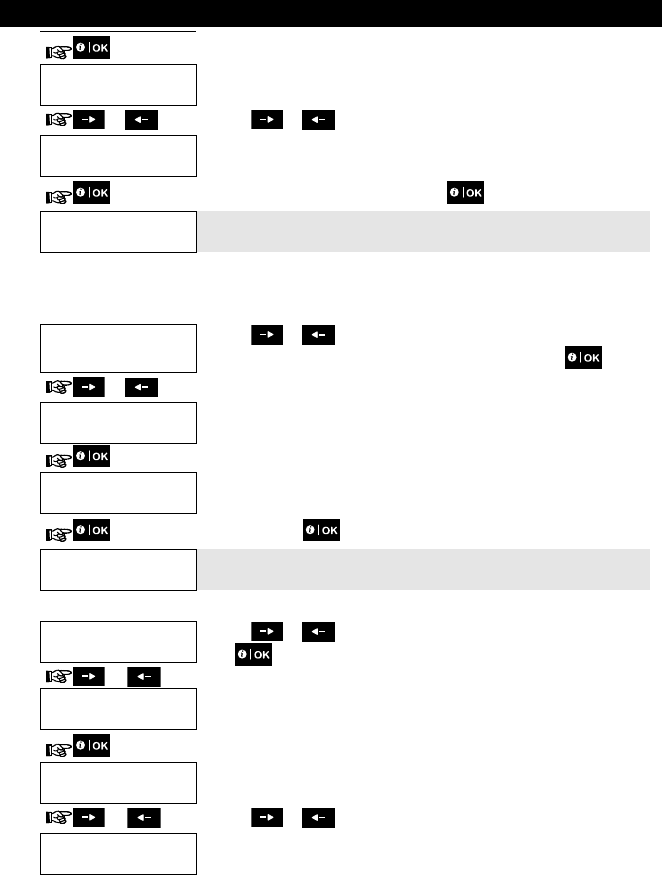
6. System Configuration
38 D-304269 KP-250 PG2 User’s Guide
REPORTED EVENTS
disable report
The display shows the currently selected option.
4. or Click the or button until the display reads the event group you wish to
be reported via private phones, for example, [alarms]. 3
REPORTED EVENTS
alarms
5. When you are satisfied with the setting, press to confirm.
REPORTED EVENTS
alarms
A "Happy Tune" ☺ sounds. The display confirms the set events to be reported. 5,
12
☺
B. To Program a Private Phone
6. REPORTED EVENTS
alarms
Click the or button until the display reads the desired Telephone No.
you wish to program or edit, for example, "Private tel#2", and press .
or
7. Private tel#2
8. Private tel#2
8032759333 To program or edit the phone number, at the blinking cursor position enter the
phone number, for example, “8032759333”, using the numerical keypad. 6, 7
9. When done, press to confirm.
Private tel#2
8032759333 A "Happy Tune" ☺ sounds and the display confirms the telephone number. 8, 12
C. To Program the Number of Redial Attempts
10. Private tel#2
Click the or button until the display reads [REDIAL ATTEMPTS] and
press .
or
11. REDIAL ATTEMPTS
3 alarms
REDIAL ATTEMPTS
3 alarms
The display shows the currently selected option.
12. or Click the or button until the display reads the desired number of redial
attempts, for example, "4 attempts". 9
REDIAL ATTEMPTS
4 alarms
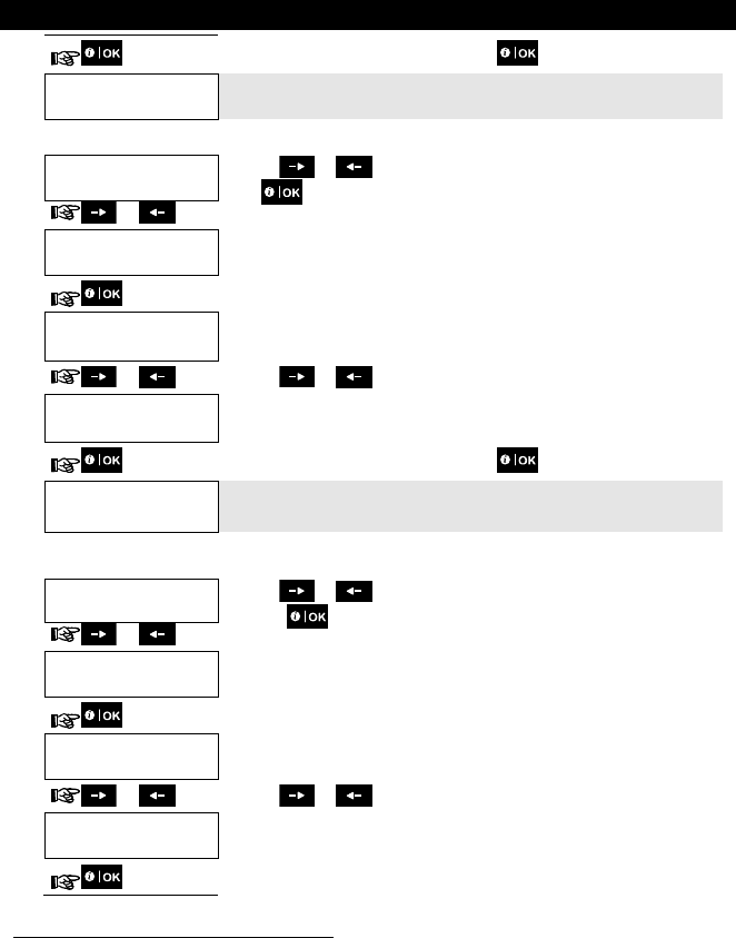
6. System Configuration
D-304269 KP-250 PG2 User’s Guide 39
13. When you are satisfied with the setting, press to confirm.
REDIAL ATTEMPTS
4 alarms
A "Happy Tune" ☺ sounds. The display confirms the set number of redial
attempts. 5, 12
D. To Program two-way voice communication
14. REDIAL ATTEMPTS
4 attempts
Click the or button until the display reads [Two Way Voice] and
press .
or
Two way voice
enable
15.
Two way voice
enable
The display shows the currently selected option.
16. or Click the or button to select the voice communication method, for
example, "disable". 10
Two way voice
disable
17. When you are satisfied with the setting, press to confirm.
Two way voice
disable A "Happy Tune" ☺ sounds. The display confirms the desired two-way voice
communication method. 5, 12
E. To Program the Acknowledge Method
18. Two way voice
disable Click the or button until the display reads [TEL. ACKNOWLEDGE]
and press to confirm.
or
TEL.ACKNOWLEDGE
by single ack
19.
TEL.ACKNOWLEDGE
by single ack
The display shows the currently selected option.
20. or Click the or button until the display reads the desired acknowledge
method, for example, "by all ack". 11
TEL.ACKNOWLEDGE
by all ack
21.
Refers to system that is connected to the Voice Box
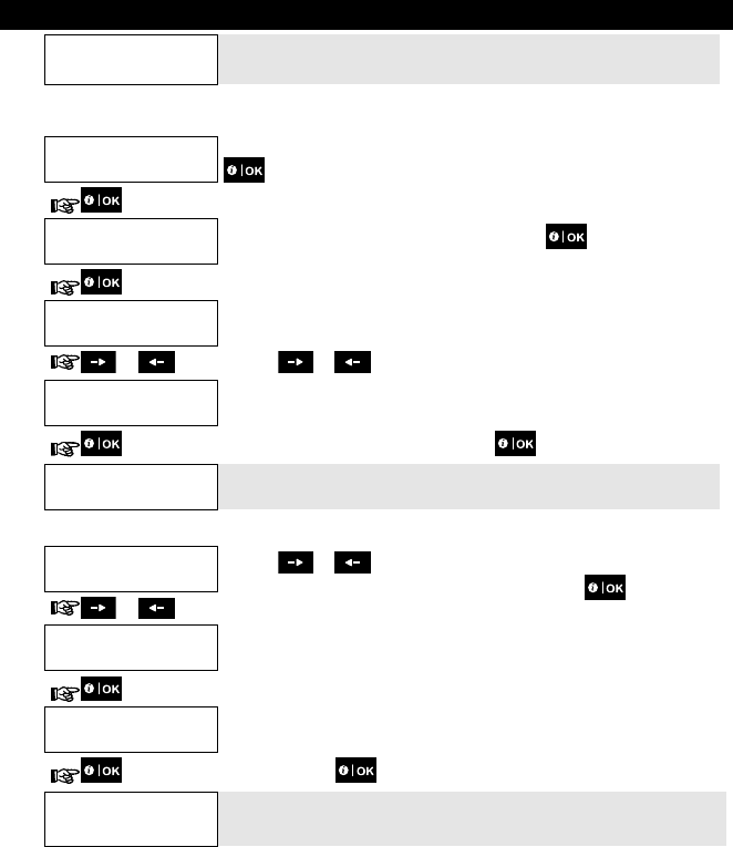
6. System Configuration
40 D-304269 KP-250 PG2 User’s Guide
TEL.ACKNOWLEDGE
by all ack A "Happy Tune" ☺ sounds and the display confirms the set acknowledge
method. 5, 12
SMS REPORT
A. To Program Events to be Reported by SMS
1. SMS REPORT
Enter the [USER SETTINGS] menu, select the [SMS REPORT] option and press
. 1
2. REPORTED EVENTS
disabled When the display reads [REPORTED EVENTS] press .
REPORTED EVENTS
disabled
The display shows the currently selected option.
3. or Click the or button until the display reads the event group you wish to
be reported via SMS, for example, [alarms]. 4
REPORTED EVENTS
alarms
4. When you are satisfied with the setting, press to confirm.
REPORTED EVENTS
alarms
A "Happy Tune" ☺ sounds and the display confirms the set events to be reported.
5, 12
B. To Program SMS Telephone Numbers
5. REPORTED EVENTS
disabled Click the or button until the display reads the SMS phone number you
wish to program or edit, for example, "SMS tel#2", and press .
or
6. SMS tel#2
7. SMS tel#2
To program or edit the phone number, at the blinking cursor position enter the SMS
phone number, for example, “5080168593”, using the numerical keypad. 6, 7
8. When done, press to confirm.
SMS tel#2
5080168593
A "Happy Tune" ☺ sounds and the display confirms the SMS phone number. 8, 12
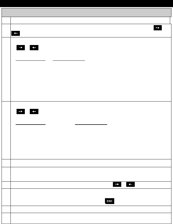
6. System Configuration
D-304269 KP-250 PG2 User’s Guide 41
Additional Information (section B.12)
1 For detailed instructions on how to select User Settings – refer to section A.1 and section A.2.
2 This option allows you to program the events to be reported. To program telephone numbers, click the or
button until the display reads the desired option.
3 The display shows the currently selected option (indicated by a symbol), for example, "
disable report
". Using
the or buttons you can now select the events you wish to be reported to private telephones
numbers according to the options provided in the tables below:
Event Group Option Events to be reported
disable report No message will be reported
alarms Alarm messages only
alerts Alert messages only
all (-op/cl) All messages, except arming & disarming
op/cl Arming and disarming (Open/close) only
all (-alerts) All messages, except alerts
all All messages
Note: “
all
” means all events including the L. BAT and AC FAIL trouble messages.
4 The display shows the currently selected option (indicated by a symbol), for example, "
disable report
". Using
the or buttons you can now select the events you wish to be reported to SMS numbers according to
the options provided in the table below:
Event Group Option Events to be reported
disable report No message will be reported
alarms Alarm messages only
alerts Alert messages only
all (-op/cl) All messages, except arming & disarming
op/cl Arming and disarming (Open/close) only
all (-alerts) All messages, except alerts
all All messages
5 The symbol now appears next to the new selected option.
6 a. The display shows the phone number currently programmed in this location (for example, 1032759641). The
cursor blinks on the first digit of the code.
b. If the location is free the display will be blank ( - - - - ).
7 You can move the cursor to the next or previous location (digit) using the or button.
8 Within the private telephone menu, you can now repeat steps 7 – 9 to program or edit another phone number.
Within the SMS menu you can now repeat steps 6 - 8 to program or edit another SMS phone number.
To end this session and return to previous menu options, press the button.
9 You can select between: "
1 attempt
"; "
2 attempts
"; "
3 attempts
"; "
4 attempts
".
10 You can select between:
"
enable
" – enables 2-way voice communication with private telephones.
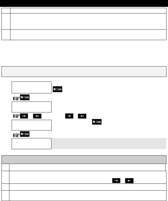
6. System Configuration
42 D-304269 KP-250 PG2 User’s Guide
"
disable
" - disables 2-way voice communication with private telephones.
11 You can select between:
"
by single ack
" – an acknowledge signal from only a single telephone will stop the reporting process.
"
by all ack
" – an acknowledge signal from all telephones is required to stop the reporting process.
12 You can now, select other options, end this session – (see section A.1 and section A.2), or quit programming (see
section A.3).
B.13 Enabling / Disabling the Squawk Option
The PowerMaster system (and its wireless sirens) can be set to produce a short "Squawk" of audible feedback to assist
you when you use your keyfob to arm (1 beep) and disarm (2 beeps) the PowerMaster system (operates in a similar
manner to a car alarm).
Here you can enable / disable the Squawk.
Carefully read the section titled "Additional Information" according to the indicated references1 etc – see table at
end of this section.
1. SQUAWK
on
Enter the [USER SETTINGS] menu, select the [SQUAWK] option and press
. 1
SQUAWK
on
The display shows the currently selected setting. 2
2. or Click the or button until the display reads the desired setting, for
example, "off" and press the button to confirm.
SQUAWK
off
3.
SQUAWK
off A "Happy Tune" ☺ sounds and The display confirms the saved setting. 3, 4
Additional Information (section B.13)
1 For detailed instructions on how to select User Settings – refer to section A.1 and section A.2.
2 a. The display shows the currently selected setting (indicated by a symbol), for example, [
SQUAWK on
].
b. You can now enable (ON) or disable (OFF) the Squawk option using the or button.
3 The symbol now appears next to the new selected option.
4 You can now select another option in the User Settings menu (see section A.1 and section A.2), or quit
programming (see section A.3).
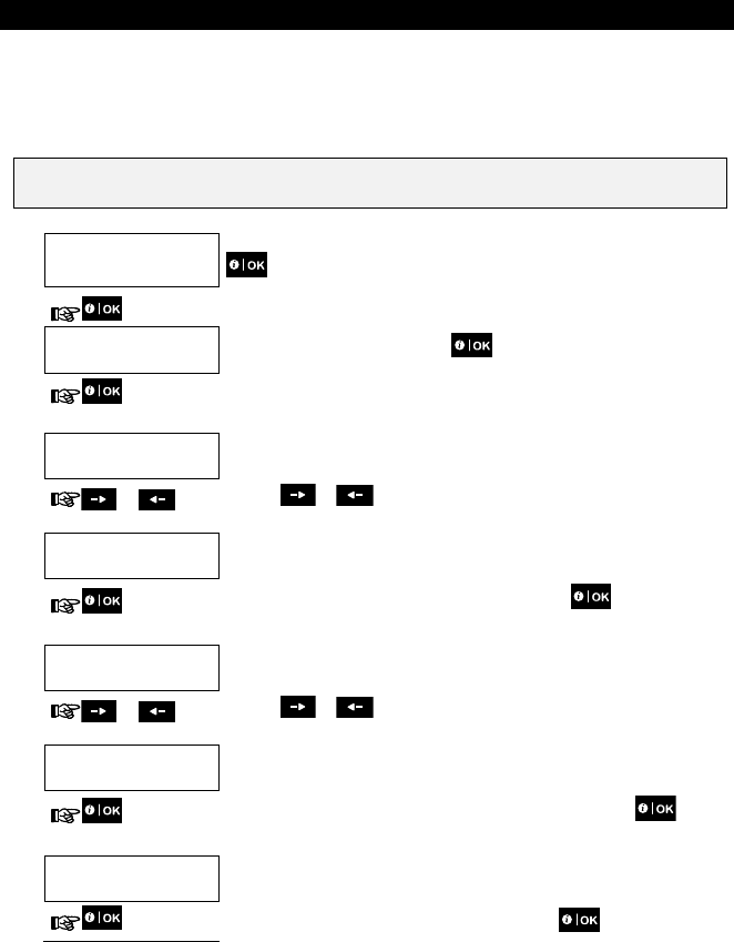
6. System Configuration
D-304269 KP-250 PG2 User’s Guide 43
B.14 Programming the Scheduler
The PowerMaster system includes a PGM output that can be used to open and close an electrically-controlled gate, or
to control a preferred electrical device via keyfobs or according to a programmable weekly time schedule.
Here you can schedule the PGM output for up to 4 different ON/OFF time activations per any desired day or days of
the week. In addition, you can schedule a "Daily" schedule that applies to every day of the week. It is recommended
to complete the Scheduler table (placed at the end of this section) before programming the Scheduler.
Carefully read the section titled "Additional Information" according to the indicated references1 etc – see table
at end of this section.
A. To Select the Device No.
1. SCHEDULER
Enter the [USER SETTINGS] menu, select the [SCHEDULER] option and press
. 1
2. PGM
When the display reads [PGM], press .
B. To Set the Day 2
SUNDAY
The 1st day of the scheduler is displayed.
3. or Click the or button until the display reads the day you wish to
schedule or "Daily", for example, "Tuesday". 2
TUESDAY
4. When the "day" to schedule appears on the display, press .
C. To Select the Activation No.
5. Operation No 1
The 1st operation (PGM output activation) of the scheduler is displayed. 3
or Click the or button until the display reads the operation you wish to
schedule, for example, "operation No 3".
Operation No 3
6. When the "operation No." to schedule appears on the display, press .
D. To Set the ON (Start) Time
7. Start time HH:MM
: The "start time" screen is shown on the display. 4
To set the start time of the selected operation, press the button.
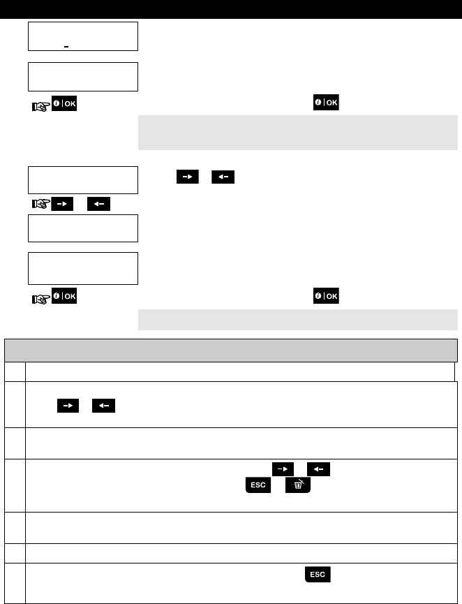
6. System Configuration
44 D-304269 KP-250 PG2 User’s Guide
8. Start time HH:MM
10:30 The display shows the current setting of the start time. 5
Start time HH:MM
00:30
Use the numerical keypad to set or change the operation ON (start) time, for
example, “00:30”. 6
9. When you are satisfied with the setting, press to confirm.
☺ Go to step 10 A "Happy Tune" ☺ sounds and the display confirms the saved start time.
To set the stop time, continue to step 10.
E. To Set the OFF (Stop) Time
10. Start time HH:MM
00:30 Click the or button until the display reads "Stop time HH:MM".
or
Stop time HH:MM
11:45
5
12. Stop time HH:MM
16:00 Use the numerical keypad to set or change the operation OFF (stop) time, for
example, “16:00”. 6
When you are satisfied with the setting, press to confirm.
A "Happy Tune" ☺ sounds and the display confirms the saved stop time. 7
Additional Information (section B.14)
1 For detailed instructions How to select the Setting Options – refer to section A.1 and section A.2.
2 To activate the selected device on every day of the week at the same time(s), use the "Daily" option. Otherwise,
use the or buttons to select the specific day (Sunday, Monday, Tuesday…etc) you wish to activate
the PGM output. You can later repeat the process for other days of the week.
3 The display shows "
operation No 1
" which is the first of the 4 ON/OFF time activations you can schedule for the
day selected in the previous step. You can later repeat the process for the other 3 activations on the selected day.
4 Here you can select either the "start time" or "stop time" using the or button. Select the time in 10
minute intervals only. To erase a displayed time, press the or button.
The screen also displays the selected time format.
5 The display shows the current start or stop time setting of the selected activation with the cursor blinking on the
first hour digit. If no time is programmed, the time display will be (00:00).
6 For detailed explanation of how to set the time - refer to Section B.8B.
7
To end this session and return to the previous "operation" menu, press the button.
To select other menu options or to quit programming, follow the instructions in sections A.2 and A.3.
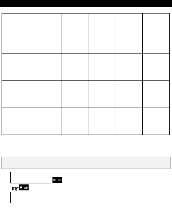
6. System Configuration
D-304269 KP-250 PG2 User’s Guide 45
Scheduler Table
Device Device
Description
Day Operation 1 Operation 2 Operation 3 Operation 4
PGM Monday ON: _ _: _ _
OFF: _ _: _ _
ON: _ _: _ _
OFF: _ _: _ _
ON: _ _: _ _
OFF: _ _: _ _
ON: _ _: _ _
OFF: _ _: _ _
PGM Tuesday ON: _ _: _ _
OFF: _ _: _ _
ON: _ _: _ _
OFF: _ _: _ _
ON: _ _: _ _
OFF: _ _: _ _
ON: _ _: _ _
OFF: _ _: _ _
PGM Wednesday ON: _ _: _ _
OFF: _ _: _ _
ON: _ _: _ _
OFF: _ _: _ _
ON: _ _: _ _
OFF: _ _: _ _
ON: _ _: _ _
OFF: _ _: _ _
PGM Thursday ON: _ _: _ _
OFF: _ _: _ _
ON: _ _: _ _
OFF: _ _: _ _
ON: _ _: _ _
OFF: _ _: _ _
ON: _ _: _ _
OFF: _ _: _ _
PGM Friday ON: _ _: _ _
OFF: _ _: _ _
ON: _ _: _ _
OFF: _ _: _ _
ON: _ _: _ _
OFF: _ _: _ _
ON: _ _: _ _
OFF: _ _: _ _
PGM Saturday ON: _ _: _ _
OFF: _ _: _ _
ON: _ _: _ _
OFF: _ _: _ _
ON: _ _: _ _
OFF: _ _: _ _
ON: _ _: _ _
OFF: _ _: _ _
PGM Sunday ON: _ _: _ _
OFF: _ _: _ _
ON: _ _: _ _
OFF: _ _: _ _
ON: _ _: _ _
OFF: _ _: _ _
ON: _ _: _ _
OFF: _ _: _ _
PGM Daily ON: _ _: _ _
OFF: _ _: _ _
ON: _ _: _ _
OFF: _ _: _ _
ON: _ _: _ _
OFF: _ _: _ _
ON: _ _: _ _
OFF: _ _: _ _
B.15 Enabling / Disabling Voice Option
The system allows you to enable or disable status-dependent, pre-recorded verbal messages that are heard over the
connected voice box.
Here you can enable / disable the Voice Option.
Carefully read the section titled "Additional Information" according to the indicated references1 etc – see table at
end of this section.
1. VOICE OPTION
enable
Enter the [USER SETTINGS] menu, select the [VOICE OPTION] option and press
. 1
2. VOICE OPTION
enable
The display shows the currently selected setting. 2
Refers to system that is connected to the Voice Box
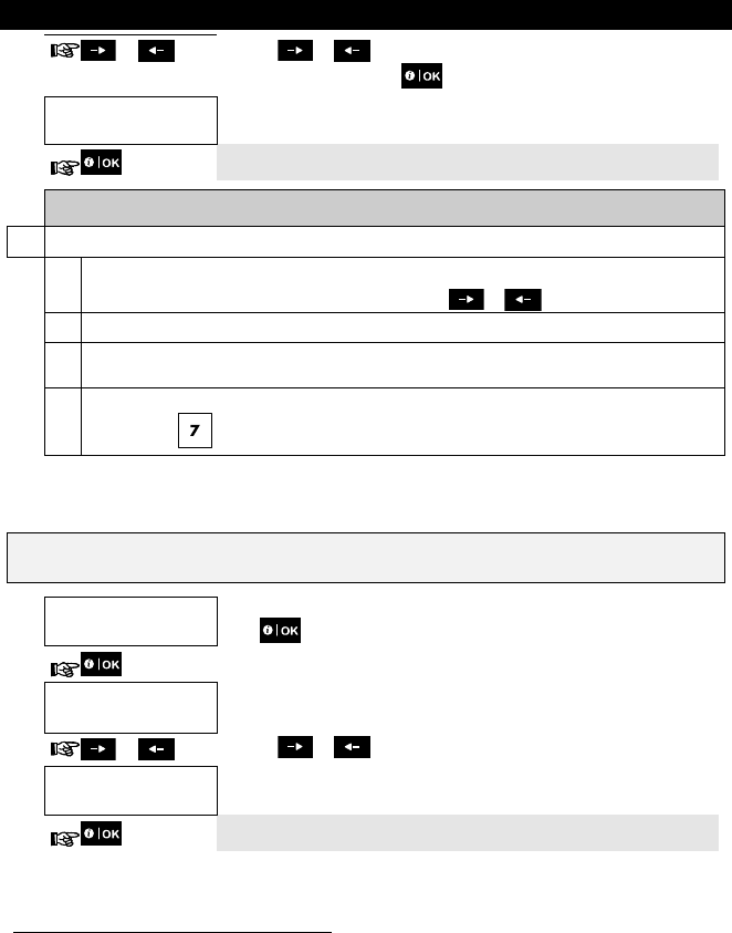
6. System Configuration
46 D-304269 KP-250 PG2 User’s Guide
or Click the or button until the display reads the desired setting, for
example, "disable" and press to confirm.
VOICE OPTION
disable
3
3. A "Happy Tune" ☺ sounds and the display confirms the saved setting.4, 5
Additional Information (section B.15)
1 For detailed instructions on how to select the Setting Options – refer to section A.1 and section A.2.
2 a. The display shows the currently selected setting (indicated by a symbol), for example, "
enable
".
b. You can now enable or disable the voice option using the or button.
3 The symbol now appears next to the newly selected option.
4 You can now select another option in the User Settings menu (see section A.1 and section A.2), or quit
programming (see section A.3).
5 If you have selected "
enable
", make sure that the voice prompts can be heard over the panel loudspeaker
by pressing the key on the KP-250 PG2 keypad.
B.16 Adjusting the Volume of the Control Panel or External Box
The KP-250 PG2 allows you to adjust the volume of the PowerMaster control panel or an external voice box.
Here you can increase or decrease the loudness.
Carefully read the section titled "Additional Information" according to the indicated references1 etc – see table at
end of this section.
1. PANEL VOLUME
Enter the [USER SETTINGS] menu, select the [PANEL VOLUME] option and
press . 1
2. PANEL VOLUME
2
or Click the or button repeatedly to increase or decrease the loudness.
PANEL VOLUME
3
3. A "Happy Tune" ☺ sounds and the display confirms the saved setting.4
Refers to a control panel that is connected to the Voice Box
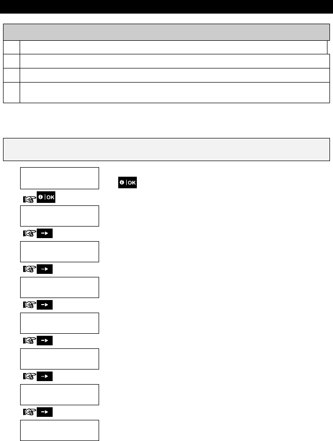
6. System Configuration
D-304269 KP-250 PG2 User’s Guide 47
Additional Information (section B.16)
1 For detailed instructions on how to select the Setting Options – refer to section A.1 and section A.2.
2 The display shows the currently selected setting (indicated by a symbol).
3 indicates the lowest volume level and indicates the highest.
4 You can now select another option in the User Settings menu (see section A.1 and section A.2), or quit
programming (see section A.3).
B.17 Serial Number
The SERIAL NUMBER menu enables reading the system serial number and similar data for support purposes only.
Here you can read the system serial number and other relevant data.
Carefully read the section titled "Additional Information" according to the indicated references1 etc – see table at
end of this section.
1. SERIAL NUMBER
Enter the [USER SETTINGS] menu, select the [SERIAL NUMBER] option and
press . 1
2. PRODUCT SN
0907030000.
Displays the control panel serial number.
3. SW CAT & SN
JS702275 K18.022
Displays the control panel software version.
4. LCD CAT SN
JS700421 v1.0.02
Displays the control panel keypad software version. 2
5. PANEL ID
100005
Displays the control panel ID for PowerManage connectivity.
6. PYTHON VERSION
FFFFFFFFF
Displays the GSM image transfer software version.
7. EE CAT & SN
J-702271 K18.022
Displays the control panel default version.
8. KP250 SW VER
01.00.09
Displays the KP-250 PG2 keypad software version.
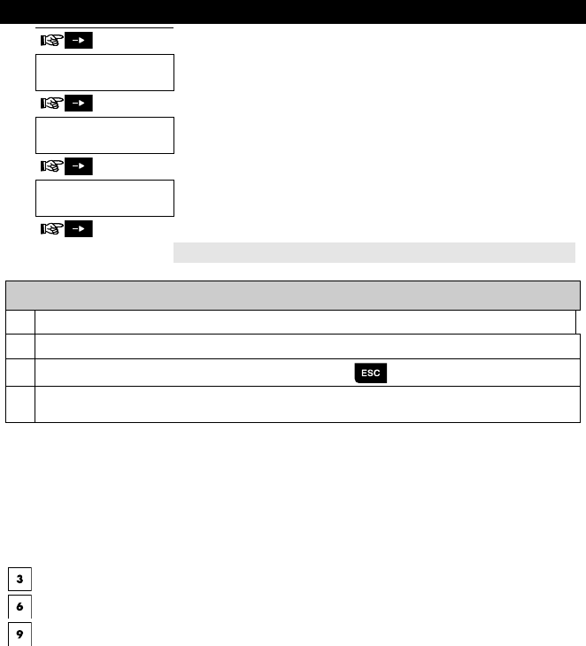
7. Advanced Features
48 D-304269 KP-250 PG2 User’s Guide
9. KP250 cat.number
70245100
Displays the KP-250 PG2 keypad catalog number.
10. RSU VERSION
7S702415 K01.034
Displays the software upgrade communicator version
11. BOOT VERSION
7S702412 K01.022
Displays the software upgrade boot/programmer version
Return to step 2 3, 4
Additional Information (section B.17)
1 For detailed instructions on how to select the Setting Options – refer to section A.1 and section A.2.
2 Refers to PowerMaster-30 G2 only.
3
To end this session and return to previous menu options, press the button.
4 You can now select another option in the User Settings menu (see section A.1 and section A.2), or quit
programming (see section A.3).
7. Advanced Features
Control Options and Pushbuttons
The system allows manual or automatic remote control of a device connected to the PGM output.
The user defines the ON and OFF times via the Scheduler (see Chapter 6, B.14 Programming the Scheduler). The
installer determines which zone sensors will switch the remote controlled appliances on and off. However, the decision
whether the remote controlled appliance will respond as programmed is up to you (see next table).
Key Function
Manual activation of a light or other household electrical appliance that is connected to PGM output.
Manual deactivation of a light or other household electrical appliance that is connected to PGM output.
Selecting the active automatic control method:
Sensors: The appliance is controlled by sensors (assigned by the installer for this).
Timer: The appliance is controlled by timer (ON and OFF times are defined by the installer).
Both: The appliance is controlled by sensors as well as by a timer.
Examples of benefits gained by automatic remote control:
Timer Control. When you are away, the timed activation / de-activation of an electrical appliance.
Zone Control. Upon disturbance of a perimeter zone, the electrical device is switched on.
Note: Automatic activation and deactivation of electrical appliance depends also on the Scheduler setup (see
Chapter 6, B.14 Programming the Scheduler).
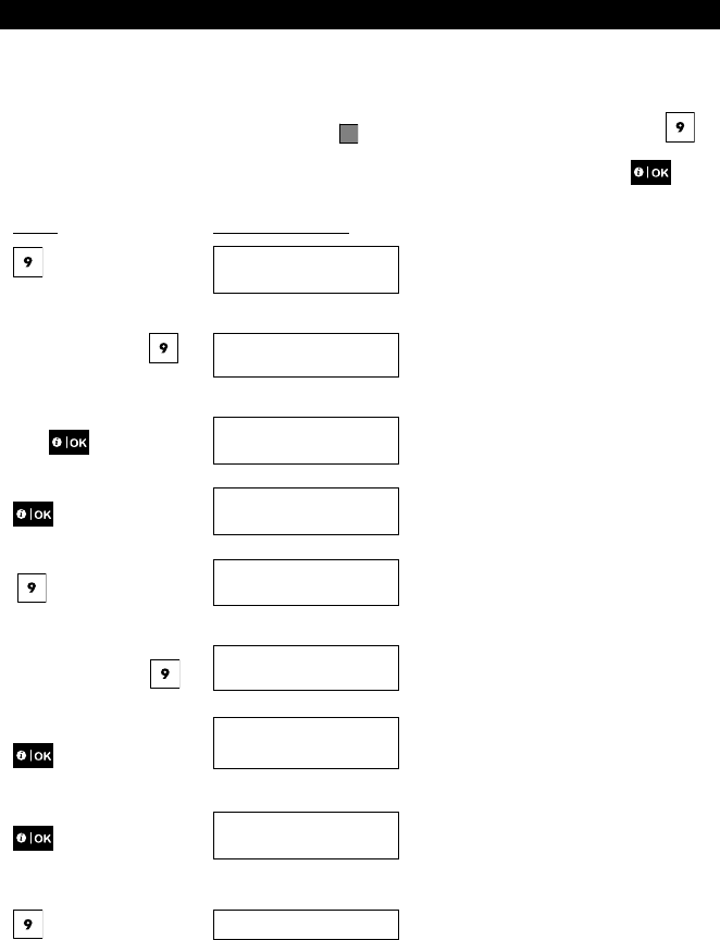
7. Advanced Features
D-304269 KP-250 PG2 User’s Guide 49
Automatic ON/OFF Control
You can select two of four options:
By Timer ON By timer OFF
By sensor ON By sensor OFF
The presently active options are shown with a dark box ( ) at the far right. To view the 2 other options click the
button.
A presently inactive option is shown without a dark box at the far right. The dark box will appear if you click while
the option is displayed. A “Happy Tune” indicates successful saving of a new option.
PRESS RESULTING DISPLAY
BY TIMER ON
(If this is the default)
If not satisfied - press
BY TIMER OFF
If satisfied -
press
BY TIMER OFF
BY TIMER OFF
BY SENSOR ON
(If this is the default)
If not satisfied - Press
BY SENSOR OFF
If satisfied -
BY SENSOR OFF
BY SENSOR OFF
HH:MM READY
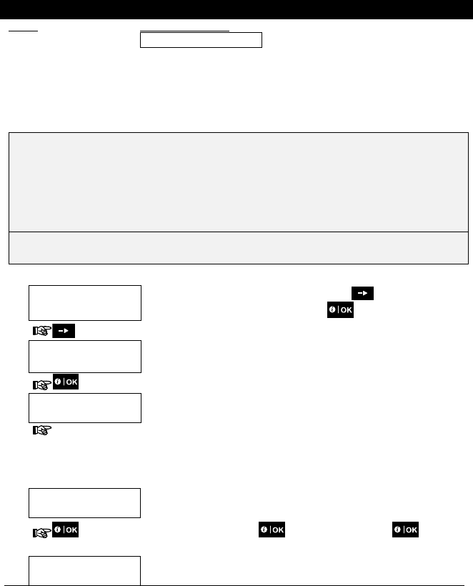
8. Periodic Test by User Code
50 D-304269 KP-250 PG2 User’s Guide
PRESS RESULTING DISPLAY
8. Periodic Test by User Code
The components of your security system are designed to be maintenance-free as much as possible. Nevertheless, it is
mandatory to test the system at least once a week and after an alarm event to verify that all system sirens, detectors,
keyfobs, keypads and other peripherals function properly. Proceed as described in this section and if there is any
problem, notify your installer at once.
The test is performed in three parts:
Siren Test: Each siren of the system is automatically activated for 3 seconds (outdoor sirens with low volume). In
addition, the system tests the siren of enrolled smoke sensors.
Temperature Sensor Test: When Temperature Sensors are enrolled in the system, the KP-250 PG2 displays the
temperature of each zone in Celsius or Fahrenheit.
Other Device Test: Each of the other devices in the system is activated by the user and the display indicates which
devices were not yet tested. The "it's me" indication helps to identify the untested devices if necessary. A counter also
indicates the number of devices that remain untested.
Carefully read the section titled "Additional Information" according to the indicated references1 etc – see table
at end of this section.
A. To Enter the Periodic Test Menu
1. HH:MM READY
Make sure the system is disarmed and then press the button repeatedly until
the display reads "PERIODIC TEST" and press . 1
PERIODIC
TEST
2.
PRESENT TAG OR
ENTER CODE:
The screen will now prompt you to enter your user code or present your proximity
tag.
3. CODE/TAG Enter your User Code or present your proximity tag. 2 3
☺ Go to step 4
B. To Test the Sirens
4. SIRENS TEST
The display now reads [SIREN TEST].
5. To initiate the siren test press . Immediately after pressing , all 4
LEDs on the panel and all 5 LEDs on the KP-250 PG2 should light (LED test). 4
SIREN P
<NEXT> or <OK>
The display now reads [SIREN P], where "P" indicates the control panel siren that
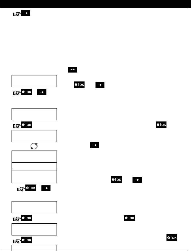
8. Periodic Test by User Code
D-304269 KP-250 PG2 User’s Guide 51
is currently being tested.
First the panel siren sounds for 3 seconds after which the PowerMaster system will
automatically repeat the procedure for the next siren enrolled in the system until all
sirens are tested. 5
You should listen to the sirens sounds and make sure that all sirens sound.
Once all the sirens have been tested, the control panel will now test the sirens of
smoke sensors that are enrolled in the alarm system. The display now reads [Zxx:
SMOKE SIREN] on the first line, and [<NEXT or <OK>] on the second line, where
"Zxx" indicates the zone number of the smoke sensor. During this time, the siren of
the tested smoke sensor will sound for up to one minute.
Press to test the siren of the next smoke sensor.
6. SIREN TEST ENDED
When all the sirens test is complete, the display reads [SIREN TEST ENDED].
Press the or the button to confirm the test and then move to the next
step for zone temperature display.
or
C. To Display the Temperature
7. TEMPERATURE TEST
The display now reads [TEMPERATURE TEST].
8. To display the temperature of zones on the KP-250 PG2, press . 6
Z01 +19.5C
Z01:Temp. Sensor
The KP-250 PG2 reads the temperature of each zone. The display alternates
between the temperature, the sensor number and the sensor location. 7
Repeatedly click the button to review the temperature of each zone (by
Temperature Sensor).
Z01 +19.5C
Living room
9. DEVICE TESTS END
When the temperature of all zones has been reviewed, the display reads
[DEVICE TESTS END]. Press the or the button to confirm the test
and then move to the next step to test the other devices.
or
D. To Test all other Devices
TEST ALL DEVICES
The display now reads [TEST ALL DEVICES].
10. To enter the devices test procedure, press .
11. NOT ACTIVE NNN
The display reads [NOT ACTIVE NNN]. NNN indicates the number of enrolled
devices in the panel that have not been tested yet. This number automatically
drops one count for every tested device. To initiate devices test, press .
Z01 NOT ACTIVE The display shows the 1st device in the list of untested devices. The display
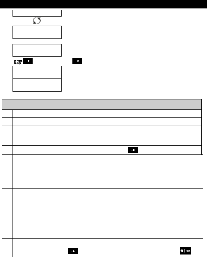
8. Periodic Test by User Code
52 D-304269 KP-250 PG2 User’s Guide
Z01 CONTACT alternates between the device number, the device type (e.g. magnetic contact,
keyfob, keypad, etc.), and the device location.
The test is performed by activating each device as explained in point 8 in the table
below.
Z01 NOT ACTIVE
FRONT DOOR
Z01 IS ACTIVATE
Z01 CONTACT Once the device has been activated, the display will change accordingly.
12. Click to scroll through the list of all untested devices. 9
13. DEVICE TESTS END
When all devices have been activated, the display reads [DEVICE TESTS END]
followed by [HH:MM READY].
HH:MM READY
Additional Information (Periodic Test)
1 Display shown in disarm state when all zones are secured (00:00 or other digits show present time).
2 If you have not already changed your personal code number, use the default setting – 1111.
3 If the INSTALLER CODE is used to enter the Periodic Test instead of the USER CODE, the devices LED will
also provide the link quality indication – refer to Chapter 4 of the KP-250 PG2 Installer’s Guide, Periodic Test
by Installer Code.
4 To skip the SIRENS TEST and select the other devices TEST, press .
5 The Periodic test can be performed on a maximum of two wireless sirens (including one internal sounder) and
the sirens of enrolled smoke sensors. Outdoor sirens are activated with low volume.
6 If no temperature sensor is enrolled in the system, the display reads
"NO EXISTING DEV.
".
7 The displayed temperature can be in Celsius or Fahrenheit according to the programmed settings of the
Temperature Sensor.
8 To activate system devices during the "Periodic Test"; make sure the device LED lights when activated:
Contact sensor: Open or close the door or window protected by the contact.
Motion sensors: Perform a "walk test" of the detector as explained in the detector's datasheet.
Smoke sensors: Perform a "Diagnostic test" as explained in the detector's datasheet.
Keyfob: Activate any of the keyfob buttons.
Keypads: Press the keypad’s
button.
Other devices: In general, follow the "Diagnostic Tests" described in the device's datasheet or activate any
of its functions.
9 a. Three seconds after the device is displayed, the device LED blinks to assist you to identify ("it's me").
b. To end the session, press the button until the display reads [<OK> TO LEAVE] then press .
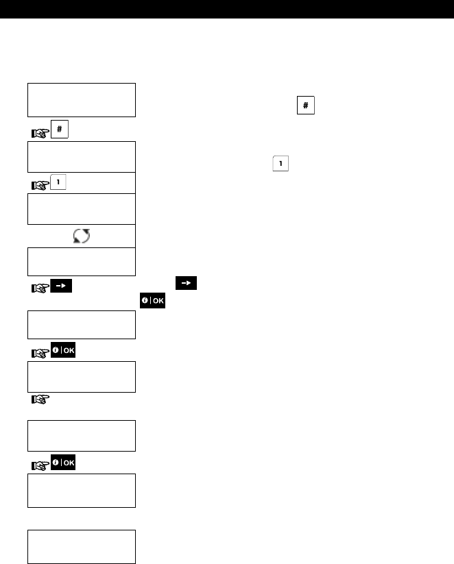
8. Periodic Test by User Code
D-304269 KP-250 PG2 User’s Guide 53
Periodic Test per Partition
In addition to the regular Periodic Test, you can also test zones for enrolled sensors (excluding temperature sensors
and sirens) that are assigned to a selected partition.
To conduct the periodic Test per Partition 1
1. HH:MM READY
TROUBLE
Make sure the selected partition is disarmed and the other partitions are not in exit
or entry delay and then press the partition ( ) button.
2. SELECT PARTITION
When the display reads [SELECT PARTITION], press the partition number of the
zones you wish to test, for example, (Partition 1).
3. PARTITION 1
N.RDY MEMORY
PARTITION 1
N.RDY TROUBLE
4. Press the button repeatedly until the display reads [PERIODIC TEST] and press
.
PERIODIC TEST
5.
PRESENT TAG OR
ENTER CODE
The screen will now prompt you to or enter your Master user code. 2
6. Enter Master user
code
P1 SENSORS TEST
3
7.
8. NOT ACTIVE NNN
The display reads [NOT ACTIVE NNN]. NNN indicates the number of enrolled
devices in the panel that have not been tested yet. This number automatically drops
one count for every tested device.
Test per partition is performed by activating each device as explained in point 4 in
the Additional Information table below.
After a device has been activated, the control panel reads [Zxx IS ACTIVATED]
and the "N" indicator drops one count.
After all devices have been tested, the control panel reads [DEVICE TESTS END].
DEVICE TESTS END
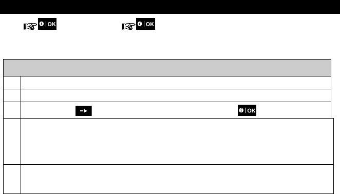
8. Periodic Test by User Code
54 D-304269 KP-250 PG2 User’s Guide
9. Press . 5
☺ Return to step 3
Additional Information (Periodic Test per Partition)
1 Partitioning must be enabled by your installer.
2 If you have not already changed your personal code number, use the default setting – 1111.
3
To abort, press the button; the display reads [<OK> TO Exit]. Press the button.
4 To activate system devices during the "Periodic Test"; make sure the device LED lights when activated:
Contact sensor: Open or close the door or window protected by the contact.
Motion sensors: Perform a "walk test" of the detector as explained in the detector's datasheet.
Smoke sensors: Perform a "Diagnostic test" as explained in the detector's datasheet.
5 Periodic test per partition will be interrupted (the panel returns to selected partition display) upon occurrence of
one of the following: 1) Disarm event by keyfob, keypad or pendant assigned to a selected partition; 2) PANIC,
FIRE or EMERGENCY event.
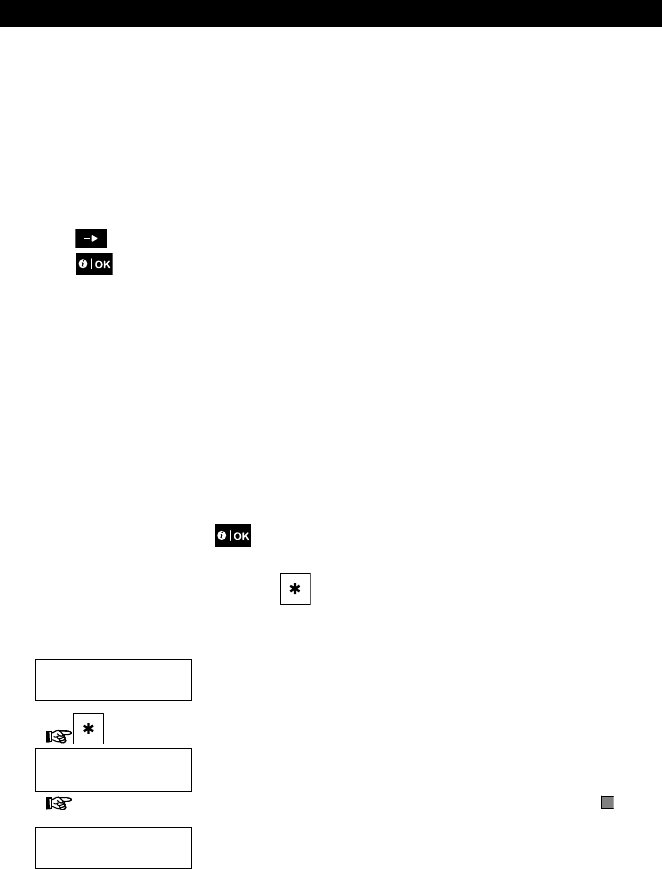
9. Maintenance
D-304269 KP-250 PG2 User’s Guide 55
9. Maintenance
Replacing Wireless Devices Batteries
The wireless devices supplied with your system are powered by batteries that last several years, in normal use.
However, if and when a battery becomes weak, the device itself sends a “low battery” message to the control panel, and
a low battery trouble message is displayed together with the zone information (see Chapter 5 – Trouble Indications).
The respective manuals of these sensors or devices should be consulted for proper battery replacement guidelines to
be performed by the installer.
Accessing 24-Hour Zones
To access a sensor defined as a 24-hour zone without causing an alarm:
Click - the display will read: USER SETTINGS.
Click - the display will read: PRESENT TAG OR ENTER CODE ___.
Key your secret 4-digit <User Code> or present your tag - the buzzer will play the “happy Tune” (- - - ––––).
You have 4 minutes during which the 24-hour sensor can be opened and accessed. When the 4 minutes are up, the
system will automatically revert to the normal mode.
Event Log by User Code
All events are memorized in an event log that contains up to 100 entries. You can access this log, review the events one
by one and draw functional conclusions.
Note: Up to 250 (PowerMaster-10 G2) / 1000 (PowerMaster-30 G2 / PowerMaster-33 G2) events are stored in the
event log that can be reviewed via the Remote Programmer PC software application or by the remote PowerManage
server.
If the event log fills up completely, the oldest event is deleted upon registration of each new event.
The date and time of occurrence are memorized for each event. When reading the event log, events are shown in
chronological order - from the newest to the oldest. The event description is shown with the date and time. The display
is shown several times, until you click to move on to an older event, or until the “no action” 4-minute timeout
restores the system to the normal operating mode.
Access to the event log is provided by clicking the button and then keying your master user code.
To get an overall view of using the log, refer to the procedure below.
To read the event log, proceed as follows:
HH:MM READY
1.
PRESENT TAG OR
ENTER CODE:
2. CODE When the KP-250 PG2 display reads [PRESENT TAG OR ENTER CODE: ],
enter the current master user code or present your tag.
KP-250
LIST OF EVENTS
The "Happy Tune" will sound and the display will read [KP-250 LIST OF
EVENTS]. (see Important Note!)
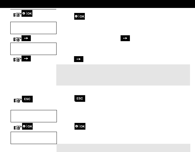
9. Maintenance
56 D-304269 KP-250 PG2 User’s Guide
3. Click the button. The latest event will be shown.
CPU LOW BATTERY
12/04/11 15:14
The event is displayed on two rows, for example, "CPU LOW BATTERY" then
"12/04/11 15:14".
The display will be shown until clicking again to move to the next event or
until the event log times out (4 minutes).
F03 DISARM
15/03/11 08:37
4. Click the button as many times as necessary to read all the required data.
Important Note! Entering an incorrect code 5 times in a row will initiate a 30-
second penalty lockout of the keypad.
Attention: The system will not allow you to erase the event log. Only the installer
is authorized to view and perform this function.
Exiting the Event Log
1. Click the button from anywhere within the event log.
The display will read [KP-250 <OK> TO EXIT].
KP-250
<OK> to Exit
2. Click the button.
HH:MM READY
The system reverts to the normal operating mode.
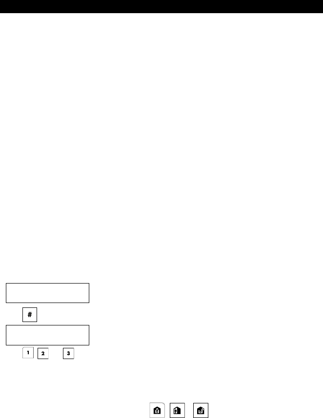
APPENDIX A: Specifications
D-304269 KP-250 PG2 User’s Guide 57
APPENDIX A: Specifications
Frequency Band (MHz) Europe and rest of world: 433-434, 868-869 USA: 912-919
Communication Protocol PowerG
Battery type Four 1.5V AA Alkaline batteries
Battery Life Expectancy 3 years (for typical use).
Low Battery Threshold 3.8 V
Power source Battery: 4.8VDC – 6VDC
AC/DC (optional): 5VDC/2A - 12VDC/1A
Back light Blue (keypad) / white (display)
Operating Temperature 0C to 55C (32F to 131F)
Humidity
A
verage relative humidity of approx. 75% non-condensing. For 30 days per year,
relative humidity may vary from 85% to 95% non-condensing.
Dimensions (WxLxD) 150x100x20mm (5-7/8 x 3-7/8 x 13/16 in)
Weight (including battery and bracket) 379 g (13 oz).
Mounting Wall-mounted or desktop
Color White
APPENDIX B: Partitioning
The KP-250 PG2 includes an optional partition feature. Partitioning is available only if your installer has enabled the
feature. Once partitioning is enabled Partitioning menus are added to the system which can be viewed on the LCD
display.
Each user code can be assigned to a combination of up to 3 partitions and each partition can be armed or disarmed
regardless of the status of the other partitions within the system. For example, you can define the garage as partition 1,
the basement as partition 2, and the house as partition 3. Since each partition is independent of other partitions, you can
arm or disarm each partition as desired without altering the states of the other partitions.
The system also supports a situation where an area is used by two or more partitions. For example, a reception area
which is common to two offices, each of which is assigned to a separate partition, will be armed only after both offices
(partitions) are armed. In the armed state the reception area will be disarmed after either office (partitions) has been
disarmed to allow the user of that office to use the reception area without generating an alarm. Such an area is termed a
"common area".
Note: Remote operation is performed per partition, or per user code defined for a particular partition, when partition is
enabled.
B1. Selecting a Partition
When operating in partition mode the first display will read:
P1: R P2: N P3: R
Press ; the display will read:
SELECT PARTITION
Press , , and to select the desired corresponding partition.
Note: After 5 seconds of no button press there will be a timeout and the display will revert to the All Partition display.
B2. Arming / Disarming the System
Before continuing, make sure that Partitioning has been enabled via the Installer Mode.
Arming/Disarming All Partitions
To arm/disarm all partitions in READY mode, press the / or button.
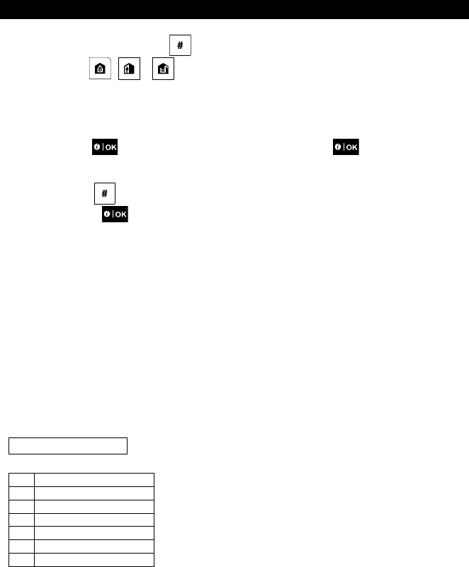
APPENDIX B: Partitioning
58 D-304269 KP-250 PG2 User’s Guide
Arming/Disarming a Single Partition
To arm/disarm a single partition, press the button on the KP-250 PG2 and then press the Partition number: 1; 2;
or 3. Then, press the / or button.
B3. The Show Function
The show function is enabled during single/all partition(s) status and displays information that is relevant to the selected
or all partitions.
Show All Partitions
In Ready mode press , the display will show information on all partitions. Press repeatedly to view
memory / status content.
Show Single Partition
In Ready mode, press and then press the partition number. The display will show information relevant to the
selected partition. Press repeatedly to view memory / status content.
Note: After 5 seconds of no button press there will be a timeout and the display will revert to the all partition display.
B4. Siren
A partition is alarmed when receiving an event from an alarmed device assigned to that partition. Alarmed devices do
not affect partitions to which they are not assigned. A siren is common to all partitions; therefore, an alarm from one or
more partitions will activate the siren.
Siren Activity
The siren will be activated when receiving an event from an alarmed device.
Overlapping siren activations from different partitions will not cause the duration of the siren to be extended.
When the siren sounds, it will not stop until all alarmed partitions are disarmed. However if the siren is active due
to an alarm from a common area zone, and one of the partitions assigned to this area disarms the system, the
siren will also stop. In case that the alarm is initiated from a common area but continues with zones that are not
assigned to a common area, the siren will not stop until all partitions assigned to the alarmed zones are
disarmed.
In case of a fire in partition 1 and a burglary in partition 2, the siren will sound FIRE. When partition 1 is
disarmed, the siren will sound BURGLAR for the remainder of the siren timeout period.
B5. Partition Status display
Partitions status is indicated in the following manner:
P1:X P2:X P3:X
Each X value indicates a different partition state, as follows:
R Ready
N Not ready
A Away
H Home
E Exit delay
D Entry delay
- Not used
B6. Common Areas
Common areas are areas used as walkthrough zones to areas of 2 or more partitions. There may be more than one
common area in an installation depending on the layout of the property. A common area is not the same as a partition; it
cannot be armed / disarmed directly. Common areas are created when you assign a zone or zones to 2 or 3 partitions.

APPENDIX B: Partitioning
D-304269 KP-250 PG2 User’s Guide 59
Table A1 summarizes the behavior of the different zone types in a common area.
Table A1 – Common Area Definitions
Common area zone types Definition
Perimeter Acts as defined only after the last assigned partition is armed AWAY or HOME.
In case that one of the partitions is disarmed, an alarm initiated from this zone is
ignored for all assigned partitions.
Delay zones Delay zones will not trigger an entry delay unless all assigned partitions are armed. It
is, therefore, not recommended to define delay zones as common areas.
Perimeter follower Act as defined only after the last assigned partition is armed AWAY or HOME.
In case that one of the partitions is disarmed, an alarm initiated from this zone is
ignored for all assigned partitions.
In case that one of the common area assigned partitions is in a delay state (and
the other partitions are armed), the alarm will behave as a perimeter follower for
this partition only. The event will be ignored for other assigned armed partitions.
Interior Acts as defined only after the last assigned partition is armed AWAY.
In case that one of the partitions is disarmed or armed HOME, an alarm initiated
from this zone is ignored for all assigned partitions.
Interior follower Acts as defined only after the last assigned partition is armed AWAY.
In case that one of the partitions is disarmed or armed HOME, an alarm initiated
from this zone is ignored for all assigned partitions.
In case that one of the common area assigned partitions is in a delay state (and
the other partitions are armed), the alarm will behave as an interior follower for this
partition only. The event will be ignored for other assigned armed partitions.
Home / Delay Acts as a Perimeter-Follower type when all assigned partitions are armed AWAY.
Acts as a Delay type when at least one of the assigned partitions is armed HOME.
Will be ignored when at least one of the assigned partitions is disarmed.
Emergency; Fire; Flood; Gas;
Temperature; 24-hour silent;
24-hour audible; Non-alarm
Always armed.
APPENDIX C: Glossary
60 D-304269 KP-250 PG2 User’s Guide
APPENDIX C: Glossary
This list of terms is arranged in alphabetical order.
Abort Period: When an alarm is initiated, the internal built-in sounder is activated first for a limited period of time which
is the abort period set by the installer. If you cause an alarm accidentally, you can disarm the system within the abort
period before the real sirens start and before the alarm is reported to the remote responders.
Alarm: There are 2 kinds of alarm:
Loud alarm - both internal built-in sounder and external siren blare out constantly and the control panel reports the event
by telephone or otherwise.
Silent alarm - the sirens remain silent, but the control panel reports the event by telephone or otherwise.
A state of alarm is caused by:
Motion detected by a motion detector
Change of state detected by a magnetic contact detector - a closed window or door is opened
Detection of smoke by a smoke detector
Tampering with any one of the detectors
Pressing the two emergency buttons simultaneously on the panel's keypad.
Arming: Arming the alarm system is an action that prepares it to sound an alarm if a zone is “violated” by motion or by
opening a door or window, as the case may be. The control panel may be armed in various modes (see AWAY, HOME,
INSTANT and LATCHKEY).
Assigned: Refers to zones.
Associated: Refers to devices.
AWAY: This type of arming is used when the protected site is vacated entirely. All zones, interior and perimeter alike,
are protected.
Bypass: Bypassed zones are zones that are not armed when arming the system. Bypassing permits arming only part of
the system while allowing free movement of people within certain zones when the system is armed.
Chime Zones: Allow you to keep track of activity in the protected area while the alarm system is in the disarmed state.
Whenever a chime zone is "opened", the buzzer beeps twice. The buzzer doesn't beep, however, upon closing the zone
(return to normal). Residences can use this feature to annunciate visitors. Businesses can use it to signal when
customers enter the premises or when personnel enter restricted areas.
Note: A 24-hour zone or a fire zone should not be designated as a chime zone, because both zone types actuate an
alarm if disturbed while the system is in the disarmed state.
Although one zone or more are designated as chime zones, you can still enable or disable the chime function using the
chime ON/OFF button and .LED
Control Panel: The control panel is a cabinet that incorporates the electronic circuitry and microprocessor that control
the alarm system. It collects information from various sensors, processes it and responds in various ways. It also
includes the user-interface - control keys, numerical keypad, display, sounder and loudspeaker.
Default Settings: Settings that are applicable to a specific device group.
Detector: The device (apparatus) that sends an alarm, that communicates with the control panel (e.g. NEXT PG2 is a
motion detector, SMD-426 PG2 is a smoke detector)
Disarming: The opposite of arming - an action that restores the control panel to the normal standby state. In this state,
only fire and 24-hour zones will sound an alarm if violated, but an “emergency alarm” may also be initiated.
Disturbed Zone: A zone in a state of alarm (this may be caused by an open window or door or by motion in the field of
view of a motion detector). A disturbed zone is considered “not secured”.

APPENDIX C: Glossary
D-304269 KP-250 PG2 User’s Guide 61
Forced Arming: When any one of the system zones is disturbed (open), the alarm system cannot be armed. One way
to solve this problem is to find and eliminate the cause for zone disturbance (closing doors and windows). Another way
to deal with this is to impose forced arming - automatic de-activation of zones that are still disturbed upon termination
of the exit delay. Bypassed zones will not be protected throughout the arming period. Even if restored to normal
(closed), bypassed zones will remain unprotected until the system is disarmed.
Permission to “force arm” is given or denied by the installer while programming the system.
HOME: This type of arming is used when people are present within the protected site. A classic example is night-time at
home, when the family is about to retire to bed. With HOME arming, perimeter zones are protected but interior zones
are not. Consequently, motion within interior zones will be ignored by the control panel, but disturbance of a perimeter
zone will cause an alarm.
Instant: You can arm the system AWAY-INSTANT or HOME-INSTANT, thereby canceling the entry delay for all delay
zones for the duration of one arming period.
For example, you may arm the control panel in the HOME-INSTANT mode and remain within the protected area. Only
perimeter protection is active, and if you do not expect somebody to drop in while the system is armed, alarm upon entry
via the main door is an advantage.
To disarm the system without causing an alarm, use your control keypad (which is normally accessible without
disturbing a perimeter zone) or use a keyfob transmitter.
It's me: The KP-250 PG2 system includes a powerful device locator that helps you to identify the actual device
displayed on the LCD, as follows:
While the LCD displays a zone (device), the LED on the respective device flashes indicating "it's me". The "it's me"
indication appears after a certain time delay (max. 16 seconds) and will last for as long as the LCD displays the device
with a timeout of 2 minutes.
Latchkey: The Latchkey mode is a special arming mode in which designated "latchkey users" will trigger a "latchkey
message" to be sent to a telephone when they disarm the system.
For example, if parents want to be sure that their child has returned from school and disarmed the system. Latchkey
arming is only possible when the system is armed in the AWAY mode.
Magnetic Contact Sensor: A Magnet-controlled switch and a wireless transmitter in a shared housing. The sensor is
mounted on doors and windows to detect changes in state (from closed to open and vice versa). Upon sensing that a
door or window is open, the sensor transmits an “alarm” signal to the control panel. The control panel, if not armed at
that time, will consider the alarm system as “not ready for arming” until the door or window is secured and the panel
receives a “restored” signal from the same sensor.
Motion Sensor: A passive Infrared motion sensor. Upon sensing motion, the sensor transmits an alarm signal to the
control panel. After transmission, it stands by to sense further motion.
Non-Alarm Zone: Your installer can designate a zone for roles other than alarm. For instance, a motion sensor installed
in a dark stairway may be used to switch on lights automatically when someone crosses the dark area. Another example
is a miniature wireless transmitter linked to a zone that controls a gate opening mechanism.
Quick Arming: Arming without a user code. The control panel does not request your user code when you press one of
the arming buttons. Permission to use this arming method is given or denied by the installer while programming the
system.
Remote Responder: A responder can be either a professional service provider to which the home or business owner
subscribes (a monitoring station) or a family relation/friend who agrees to look after the protected site during absence of
its occupants. The control panel reports events by telephone to both kinds of responders.
Restore: When a detector reverts from the state of alarm to the normal standby state, it is said to have been “restored”.
A motion detector restores automatically after detection of movement, and becomes ready to detect again. A magnetic
contact detector restores only upon closure of the protected door or window.
Sensor: The sensing element: pyroelectric sensor, photo-diode, microphone, smoke optical sensor etc.
Smoke Detector, Wireless: A regular smoke detector and a wireless PowerG transceiver in a shared housing. Upon
detection of smoke, the detector transmits its unique identification code accompanied by an alarm signal and various
status signals to the control panel. Since the smoke detector is linked to a special fire zone, a fire alarm is initiated.
State: AWAY, HOME, AWAY-INSTANT, HOME-INSTANT, LATCHKEY, FORCED, BYPASS.
Status: AC fail, low battery, trouble, system state etc.
User Codes: The KP-250 PG2 is designed to obey your commands, provided that they are preceded by a valid security
access code. Unauthorized people do not know this code, so any attempt on their part to disarm or defeat the system is
bound to fail. Some operations, however, can be carried out without a user code as they do not degrade the security

APPENDIX C: Glossary
62 D-304269 KP-250 PG2 User’s Guide
level of the alarm system.
Zone: A zone is an area within the protected site under supervision of a specific detector. During programming, the installer
allows the control panel to learn the detector’s identity code and links it to the desired zone. Since the zone is distinguished
by number and name, the control panel can report the zone status to the user and register in its memory all the events
reported by the zone detector. Instant and delay zones are “on watch” only when the control panel is armed, and other (24-
hour) zones are “on watch” regardless of whether the system is armed or not.
APPENDIX D: Compliance with Standards
D-304269 KP-250 PG2 User’s Guide 63
APPENDIX D: Compliance with Standards
Designed to comply with Standards Europe: EN 300220-1, EN 300220-2, EN300330, EN301489, EN60950,
EN50131-1, EN50131-3, EN50131-6.
The KP-250 PG2 is compatible with the RTTE requirements - Directive
1999/5/EC of the European Parliament and of the Council of 9 March 1999
and EN50131-1 Grade 2 Class II.
USA: CFR 47 part 15
Canada: RSS 210
UK: This product is suitable for use in systems installed to conform to
PD6662:2010 at Grade 2 and environmental class 2. DD243 and BS8243.
Sweden: SSF 1014
RFID Tags: ISO-18000-2 (125 kHz)
The Power G peripheral devices have two- way communication functionality, providing additional benefits as described in the technical
brochure. This functionality has not been tested to comply with the respective technical requirements and should therefore be considered
outside the scope of the product’s certification
EN 50131-1 Security Grade Grade 2
EN 50131-1 Environmental Class Class 2
This device complies with FCC Rules Part 15 and Industry Canada license-exempt RSS standard(s). Operation is subject to the following two
conditions: (1) this device may not cause interference, and (2) this device must accept any interference, including interference that may cause
undesired operation of the device.
Le présent appareil est conforme aux CNR d'Industrie Canada applicables aux appareils radio exempts de licence. L'exploitation est
autorisée aux deux conditions suivantes : (1) l'appareil ne doit pas produire de brouillage, et (2) l'utilisateur de l'appareil doit accepter tout
brouillage radioélectrique subi, même si le brouillage est susceptible d'en compromettre le fonctionnement.
WARNING! To comply with FCC and IC RF exposure compliance requirements, the mobile version of this device should be located at a
distance of at least 20 cm from all persons during normal operation. The antennas used for this product must not be co-located or operated in
conjunction with any other antenna or transmitter.
Le dispositif doit être placé à une distance d'au moins 20 cm à partir de toutes les personnes au cours de son fonctionnement normal. Les
antennes utilisées pour ce produit ne doivent pas être situés ou exploités conjointement avec une autre antenne ou transmetteur.
The digital circuit of this device has been tested and found to comply with the limits for a Class B digital device, pursuant to Part 15 of the FCC
Rules. These limits are designed to provide reasonable protection against harmful interference in residential installations. This equipment
generates, uses, and can radiate radio frequency energy and, if not installed and used in accordance with the instructions, may cause harmful
interference to radio and television reception. However, there is no guarantee that interference will not occur in a particular installation. If this
device does cause such interference, which can be verified by turning the device off and on, the user is encouraged to eliminate the interference
by one or more of the following measures:
– Re-orient or re-locate the receiving antenna.
– Increase the distance between the device and the receiver.
– Connect the device to an outlet on a circuit different from the one which supplies power to the receiver.
– Consult the dealer or an experienced radio/TV technician.
Changes or modifications not expressly approved by Visonic Ltd. could void the user's authority to operate the equipment.
W.E.E.E. Product Recycling Declaration
For information regarding the recycling of this product you must contact the company from which you orignially purchased
it. If you are discarding this product and not returning it for repair then you must ensure that it is returned as identified by your
supplier. This product is not to be thrown away with everyday waste.
Directive 2002/96/EC Waste Electrical and Electronic Equipment.

64 D-304269 KP-250 PG2 User’s Guide
WARRANTY
Visonic Limited (the “Manufacturer") warrants this product only (the
"Product") to the original purchaser only (the “Purchaser”) against
defective workmanship and materials under normal use of the Product for
a period of twelve (12) months from the date of shipment by the
Manufacturer.
This Warranty is absolutely conditional upon the Product having been
properly installed, maintained and operated under conditions of
normal use in accordance with the Manufacturers recommended
installation and operation instructions. Products which have become
defective for any other reason, according to the Manufacturers
discretion, such as improper installation, failure to follow
recommended installation and operational instructions, neglect, willful
damage, misuse or vandalism, accidental damage, alteration or
tampering, or repair by anyone other than the manufacturer, are not
covered by this Warranty.
The Manufacturer does not represent that this Product may not be
compromised and/or circumvented or that the Product will prevent any
death and/or personal injury and/or damage to property resulting
from burglary, robbery, fire or otherwise, or that the Product will in all
cases provide adequate warning or protection. The Product, properly
installed and maintained, only reduces the risk of such events without
warning and it is not a guarantee or insurance that such events will
not occur.
THIS WARRANTY IS EXCLUSIVE AND EXPRESSLY IN LIEU OF
ALL OTHER WARRANTIES, OBLIGATIONS OR LIABILITIES,
WHETHER WRITTEN, ORAL, EXPRESS OR IMPLIED, INCLUDING
ANY WARRANTY OF MERCHANTABILITY OR FITNESS FOR A
PARTICULAR PURPOSE, OR OTHERWISE. IN NO CASE SHALL
THE MANUFACTURER BE LIABLE TO ANYONE FOR ANY
CONSEQUENTIAL OR INCIDENTAL DAMAGES FOR BREACH OF
THIS WARRANTY OR ANY OTHER WARRANTIES
WHATSOEVER, AS AFORESAID.
THE MANUFACTURER SHALL IN NO EVENT BE LIABLE FOR
ANY SPECIAL, INDIRECT, INCIDENTAL, CONSEQUENTIAL OR
PUNITIVE DAMAGES OR FOR LOSS, DAMAGE, OR EXPENSE,
INCLUDING LOSS OF USE, PROFITS, REVENUE, OR GOODWILL,
DIRECTLY OR INDIRECTLY ARISING FROM PURCHASER’S USE
OR INABILITY TO USE THE PRODUCT, OR FOR LOSS OR
DESTRUCTION OF OTHER PROPERTY OR FROM ANY OTHER
CAUSE, EVEN IF MANUFACTURER HAS BEEN ADVISED OF THE
POSSIBILITY OF SUCH DAMAGE.
THE MANUFACTURER SHALL HAVE NO LIABILITY FOR ANY
DEATH, PERSONAL AND/OR BODILY INJURY AND/OR DAMAGE
TO PROPERTY OR OTHER LOSS WHETHER DIRECT, INDIRECT,
INCIDENTAL, CONSEQUENTIAL OR OTHERWISE, BASED ON A
CLAIM THAT THE PRODUCT FAILED TO FUNCTION.
However, if the Manufacturer is held liable, whether directly or
indirectly, for any loss or damage arising under this limited warranty,
THE MANUFACTURER'S MAXIMUM LIABILITY (IF ANY) SHALL
NOT IN ANY CASE EXCEED THE PURCHASE PRICE OF THE
PRODUCT, which shall be fixed as liquidated damages and not as a
penalty, and shall be the complete and exclusive remedy against the
Manufacturer.
When accepting the delivery of the Product, the Purchaser agrees to
the said conditions of sale and warranty and he recognizes having
been informed of.
Some jurisdictions do not allow the exclusion or limitation of incidental
or consequential damages, so these limitations may not apply under
certain circumstances.
The Manufacturer shall be under no liability whatsoever arising out of
the corruption and/or malfunctioning of any telecommunication or
electronic equipment or any programs.
The Manufacturers obligations under this Warranty are limited solely
to repair and/or replace at the Manufacturer’s discretion any Product
or part thereof that may prove defective. Any repair and/or
replacement shall not extend the original Warranty period. The
Manufacturer shall not be responsible for dismantling and/or
reinstallation costs. To exercise this Warranty the Product must be
returned to the Manufacturer freight pre-paid and insured. All freight
and insurance costs are the responsibility of the Purchaser and are
not included in this Warranty.
This warranty shall not be modified, varied or extended, and the
Manufacturer does not authorize any person to act on its behalf in the
modification, variation or extension of this warranty. This warranty
shall apply to the Product only. All products, accessories or
attachments of others used in conjunction with the Product, including
batteries, shall be covered solely by their own warranty, if any. The
Manufacturer shall not be liable for any damage or loss whatsoever,
whether directly, indirectly, incidentally, consequentially or otherwise,
caused by the malfunction of the Product due to products,
accessories, or attachments of others, including batteries, used in
conjunction with the Products. This Warranty is exclusive to the
original Purchaser and is not assignable.
This Warranty is in addition to and does not affect your legal rights.
Any provision in this warranty which is contrary to the Law in the state
or country were the Product is supplied shall not apply.
Warning: The user must follow the Manufacturer’s installation and
operational instructions including testing the Product and its whole
system at least once a week and to take all necessary precautions for
his/her safety and the protection of his/her property.
1/08
KP-250 PG2 User’s Guide, D-304269 (Rev 1, 8/14)