Visonic PWRMAXPRO Security Control Panel User Manual Installers Guide Part 1 Revised
Visonic Inc. Security Control Panel Installers Guide Part 1 Revised
Visonic >
Contents
- 1. Users Manual Revised
- 2. Installars Guide Part 1 Revised
- 3. Installers Guide Part 2
- 4. Installers Guide Part 1 Revised
Installers Guide Part 1 Revised
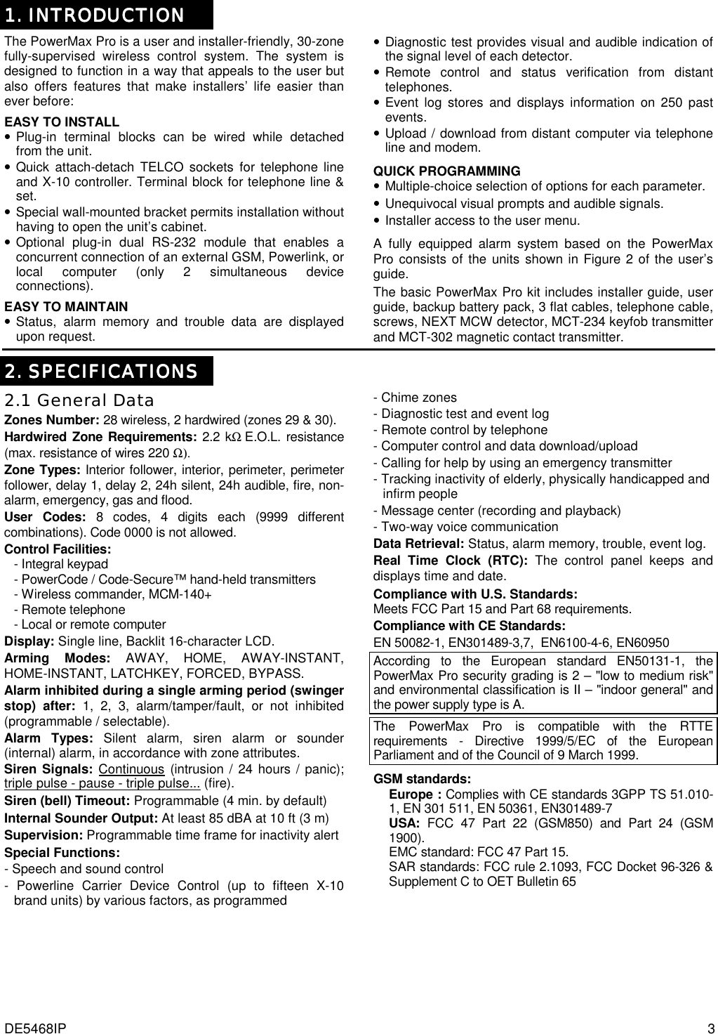
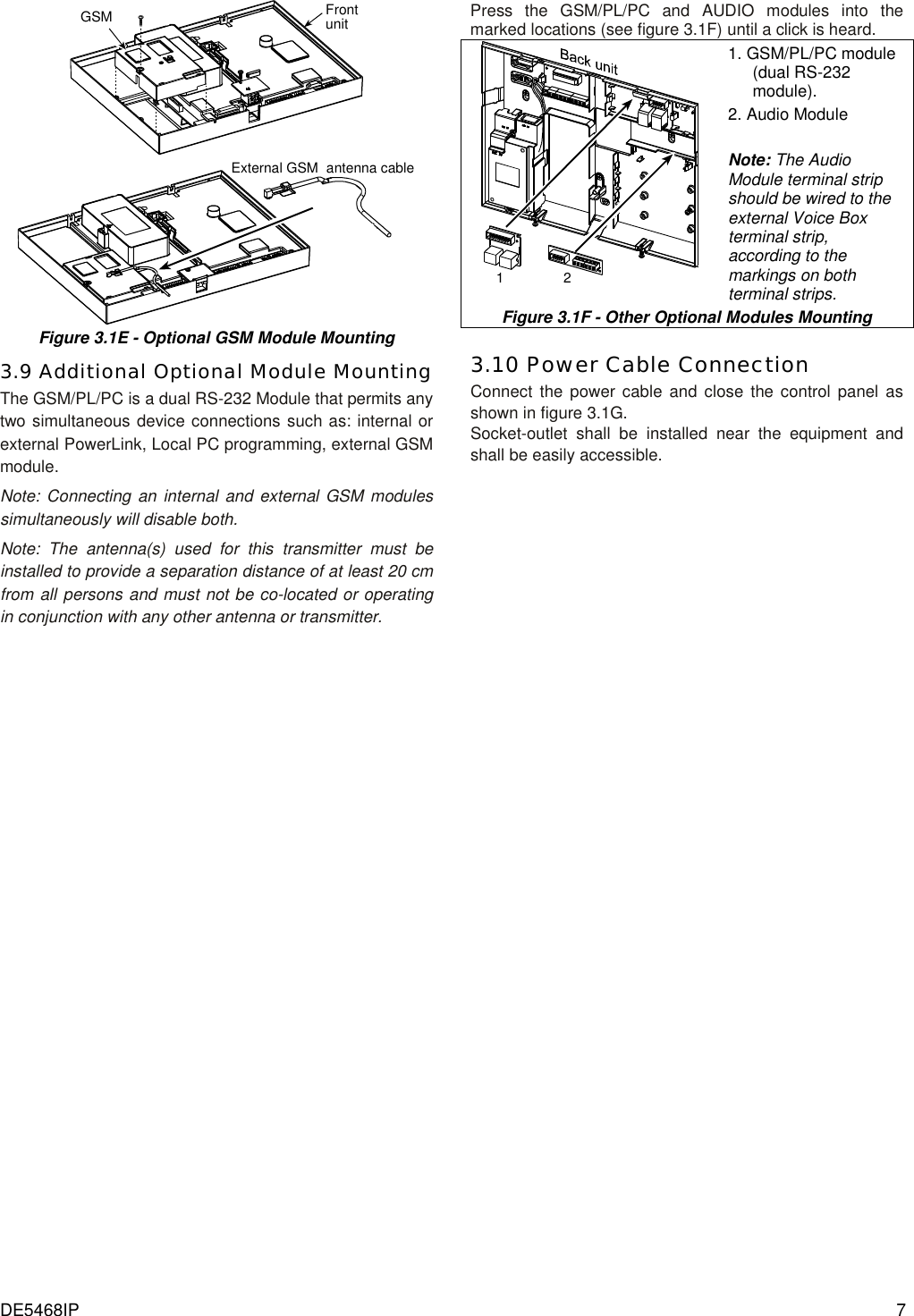
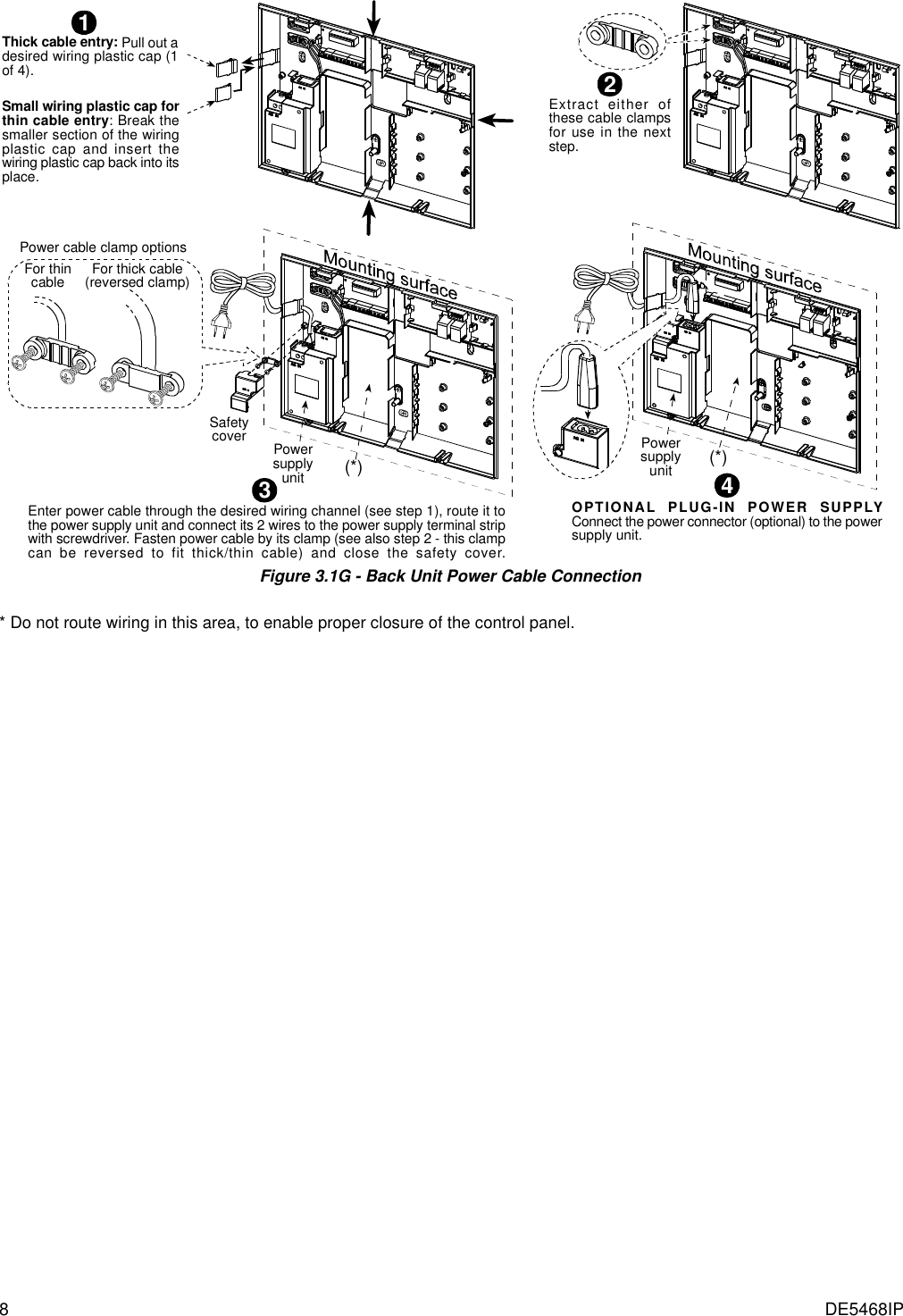
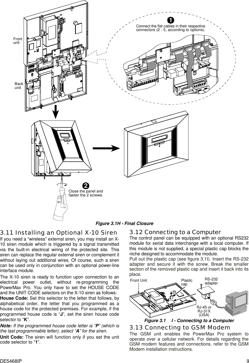
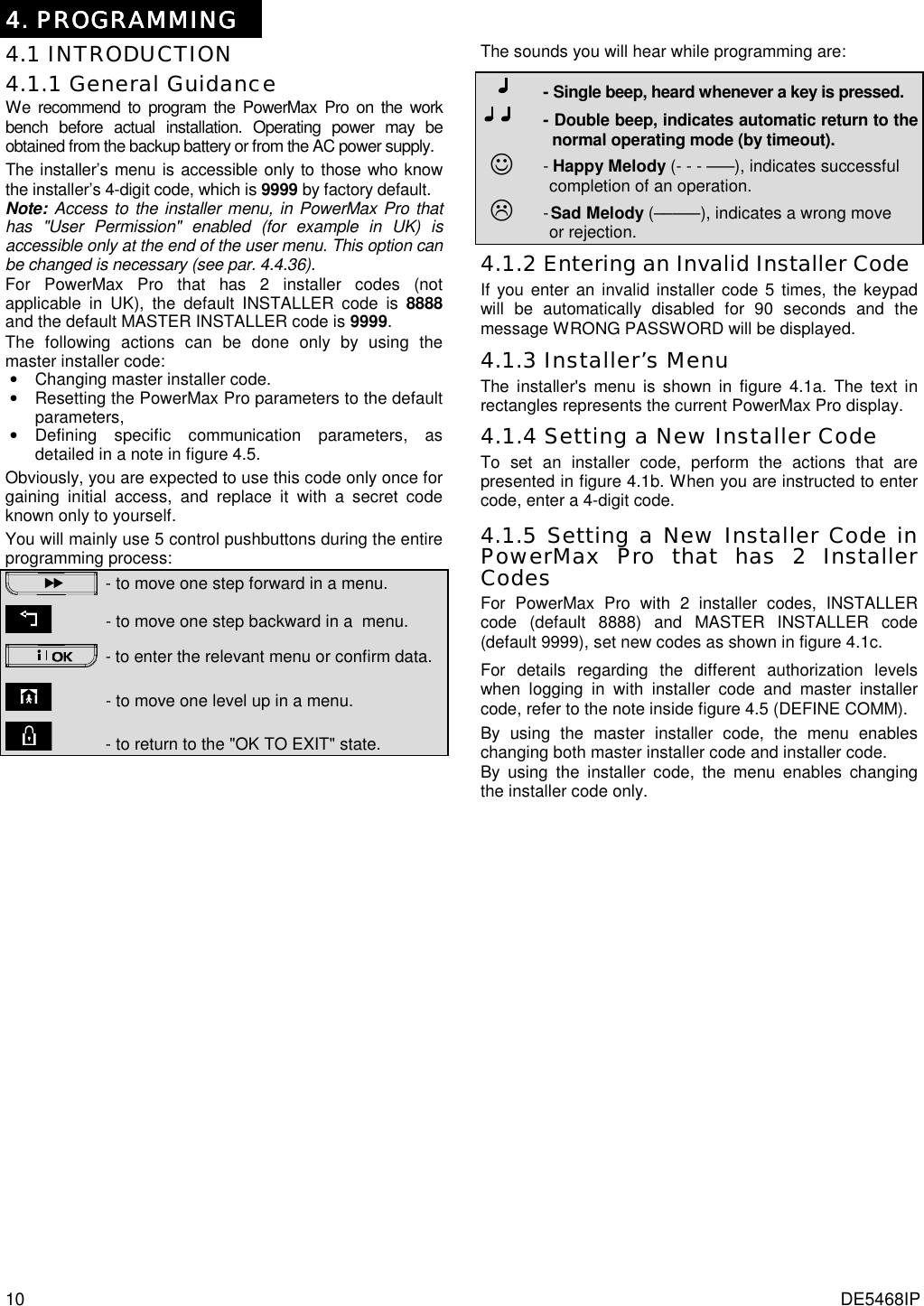
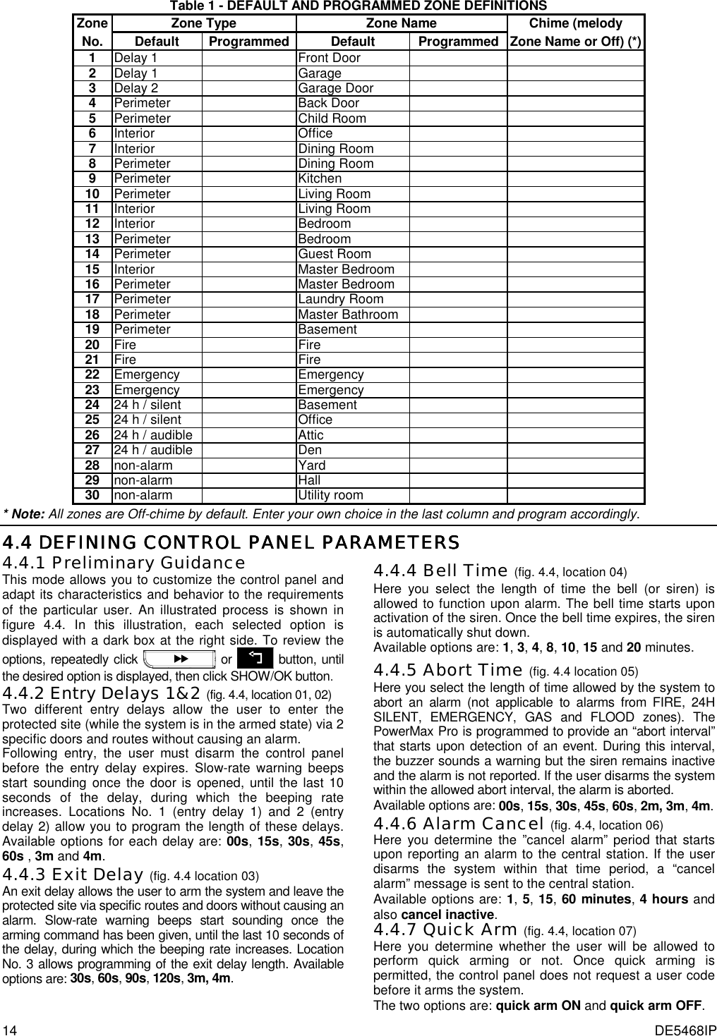
(See figure 4.10)(See fig. 4.1b & 4.1c)(See par. 4.12)(Control Panelserial numberdisplay)<OK> TO EXIT(See section 4.14)(See figure 4.6)6. DEFINE GSM(See figure 4.7)7. DEFINE PWRLNK(*) (*) Applicable only when "USER PERMIT" function is enabled (see par. 4.4.36 - USER PERMIT) Figure 4.1a - Installer’s Menu (See fig. 4.1a)1. NEW INSTL CODENEW INST. CODEINST. CODE xxxx[code] Figure 4.1b - Setting a New Installer Code (see note) By using INSTALLER CODEINST. CODE xxxxNEW INST. CODE[code]1. NEW INSTL CODE(see fig. 4.1a)(see fig. 4.1a)[code]1. NEW INSTL CODENEW MASTER CODEMASTER CODE xxxx[code]INST. CODE xxxxNEW INST. CODEBy usingMASTER INSTALLER CODEFigure 4.1c - Setting a New Installer Code in System with Inst. & Master Inst. Codes (see note) Note: Installer Code should never be programmed as “0000”. Doing so will lock the user out of the installer menu! 4444....2 ENROLLING WIRELESS DEVICES AND KEYFOB TRANSMITTERS2 ENROLLING WIRELESS DEVICES AND KEYFOB TRANSMITTERS2 ENROLLING WIRELESS DEVICES AND KEYFOB TRANSMITTERS2 ENROLLING WIRELESS DEVICES AND KEYFOB TRANSMITTERS 4.2.1 General Guidance The ENROLLING mode has 5 sub-modes: • ENROLLING TYPE (wireless devices) • ENROLL WL (wireless devices) DEVICE • ENROLL KEYFOB (multi-button CodeSecure transmitters) • ENROLL WL 1WAY KP (wireless commander MCM-140+) • ENROLL WL 2WAY KP (wireless 2-way keypad MKP-150) • ENROLL WL SIREN (wireless siren) • ENROLL PROX TAG (proximity tag) Before beginning, gather all the devices that you intend to enroll and make sure they all have batteries installed. Your control panel must recognize the unique identification code (ID) of each such device in order to supervise them, receive their signals and respond accordingly. Attention! CodeSecure transmitters are mainly used for arming/disarming and can not be enrolled to zones. For enrolling to zones, use only non-CodeSecure wireless devices.](https://usermanual.wiki/Visonic/PWRMAXPRO.Installers-Guide-Part-1-Revised/User-Guide-747811-Page-11.png)
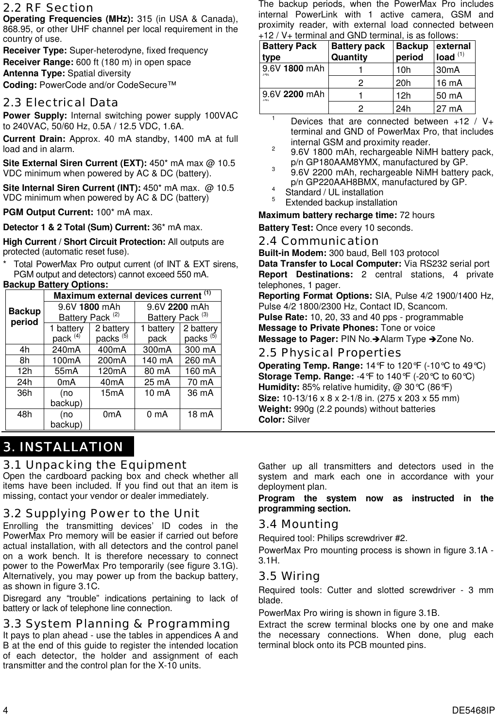
![12 DE5468IP (First display is READYor NOT READY)READY 00:00USER SETTINGSNORMAL MODEENTER CODE1. NEW INSTL CODE2. ENROLLING3. DEFINE ZONES4. DEFINE PANEL5. DEFINE COMM[installer code]INSTALLER MODEENROL WL 1WAY KP8. DEFINE OUTPUTS9. RECORD SPEECH10. DIAGNOSTICS11. USER SETTINGS12. FACTORY DEFLT13. SERIAL NUMBER<OK> TO EXIT14. START UL/DLENROLL WL DEVICEZONE No: 05ZONE No: - -[Initiate transmission)ZONE No: 05TRANSMIT NOWZONE No: 05<OFF> TO DELETEZONE No: 05[Zone No.] (e.g. 05)(**)(**)Deleting a WL DeviceEnrolling a WL DeviceSET SENSITIV.higher sensitivitylower sensitivitySelect byor(***)(****) for nextenrolling action%%[WL 1-way keypadNo. 1 to 8] (e.g. 5)1way kp No :1way kp No : 5 1way kp No : 5(**)1way kp No: 5Enrolling a wirelessCommander MCM-140+ for nextenrolling action<OFF> TO DELETEkey untilred LEDlightsTRANSMIT NOWDeleting a wirelessCommander MCM-140+1way kp No: 5*press%ENROL WL 2WAY KP[MKP-150 No.1 or 2] (e.g. 2)%2way kp No:2way kp No : 2 2way kp No : 2(**)<OFF> TO DELETETRANSMIT NOWEnrolling a wirelesskeypad MKP-150% for nextenrolling action%ENROL WL SIREN[WL siren No.1 or 2] (e.g. 2)%SIREN No :siren No : 2 siren No : 2(**)Momentarily press thewireless siren self-testbutton until a squawk isheard (1 sec. approx.)TRANSMIT NOWEnrolling awireless sirensiren No: 2% for nextenrolling actionAWAY2way kp No: 2Deleting a wirelesskeypad MKP-150Press MKP-150back tamperswitch once(see MKP-150inst. instructions)2way kp No: 26. DEFINE GSM7. DEFINE PWRLNK<OFF> TO DELETEDeleting awireless sirensiren No: 2Open WLsiren coverand removeits batteryENROLLING TYPEnormal enrollby tamperENROLL KEYFOBKeyfob No: 5Keyfob No: -TRANSMIT NOWKeyfob No: 5<OFF> TO DELETEKEYFOB No: 05KEYFOB No: 05[Keyfob No.](e.g. 5) for nextenrolling actionEnrolling a Keyfob Deleting a Keyfob(*)(**)(**)(press anykey)ENROLL PROX TAGTag No: 5Tag No: -PRESENT TAGTag No: 5<OFF> TO DELETETag No: 05Tag No: 05(Prox tag No.)(e.g. 5) for nextenrolling actionEnrolling a Prox tag Deleting a prox tag(*)(**)(**)Presenttag Figure 4.2 - Enrolling / Deleting Wireless Devices / Keyfobs / Wireless Commanders / Wireless Sirens * Keyfob & proximity tags enrolling can be performed by the installer or by the user (via USER SETTINGS menu). ** Black box in the display means that a device is enrolled (the system has learned its ID). No black box indicates that the device is not enrolled. *** Initiate either normal transmission or the device tamper function (see ENROLLING TYPE, Par. 4.2.2). **** Select "higher" sensitivity for far wireless device, "lower" for near devices. 4.2.2 Enrolling Type Here you determine whether to enroll a wireless device by normal transmission or by device Tamper function (opening its cover). Options: normal, or by tamper. 4.2.3 Enroll/Delete Wireless Devices Wireless devices include various PowerCode detectors and hand-held transmitters.](https://usermanual.wiki/Visonic/PWRMAXPRO.Installers-Guide-Part-1-Revised/User-Guide-747811-Page-12.png)
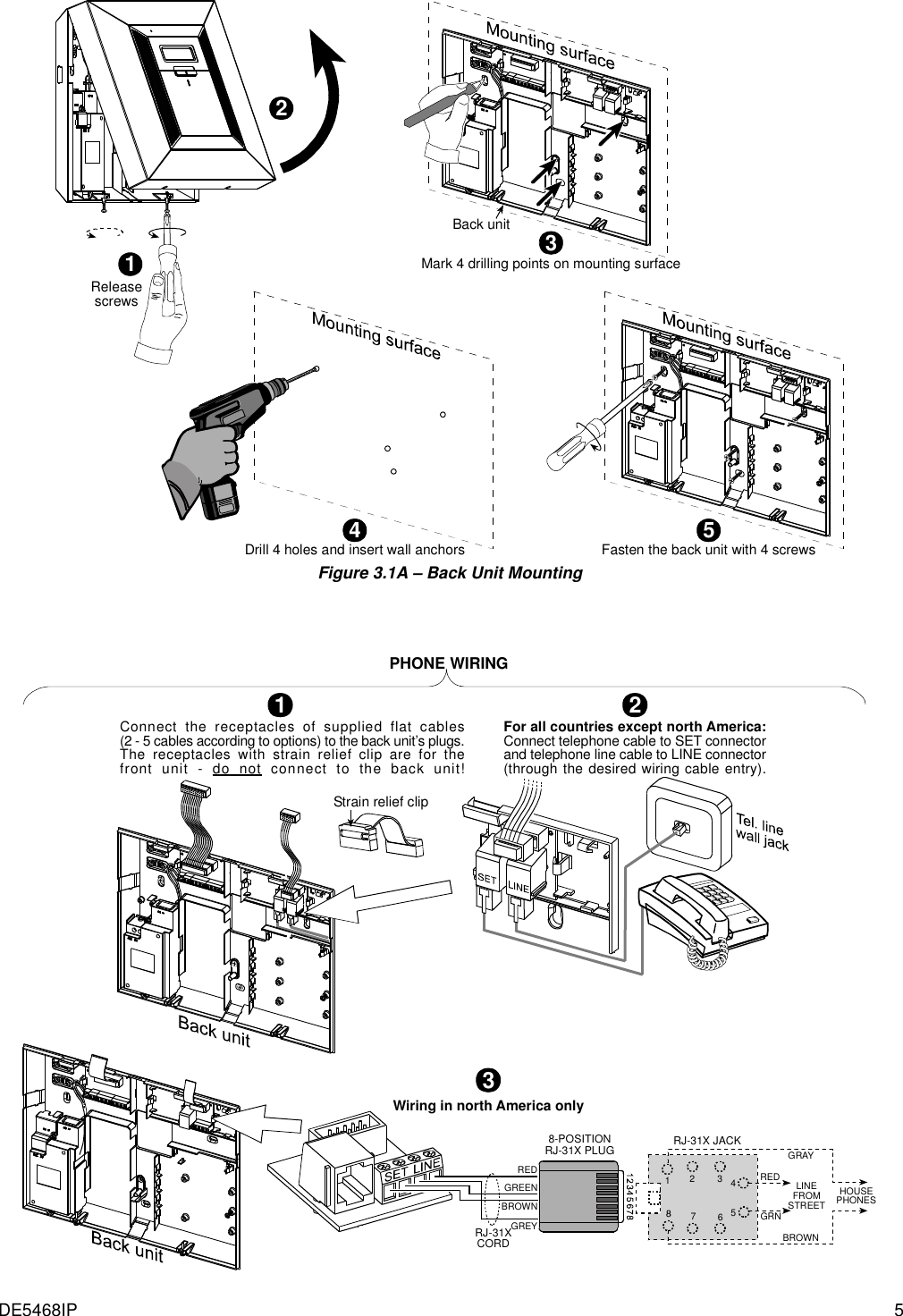
![DE5468IP 13 STOP • Before enrolling, the lens at the front of PIR and dual-technology sensors should be masked to prevent inadvertent transmission. • Make sure that magnetic contact transmitters are together with their magnets, to prevent them from sending out alarm transmissions. To enroll / delete wireless devices, refer to figure 4.2. 4.2.4 Enroll/Delete Keyfob Transmitters Keyfob transmitters are multi-button wireless CodeSecure™ transmitters. Eight system users use them for better, quicker and safer control over various system functions. To enroll / delete 1-way or 2-way keyfob transmitters, refer to figure 4.2. 4.2.5 Enroll/Delete Wireless Commander The Wireless Commander (MCM-140+) is a remote control unit that enables the user to remotely control the system. To enroll / delete up to 8 wireless commanders, refer to figure 4.2 (Enroll WL 1-way KP). 4.2.6 Enroll/Delete 2-Way Keypad The 2-way keypad, type MKP-150, enables the user to remotely control the system and also to receive data from the system (status, alarm and trouble data). To enroll up to two 2-way keypads, refer to figure 4.2. 4.2.7 Enroll/Delete Wireless Siren The wireless siren is a remote siren that is activated upon predefined events by the PowerMax Pro system. To enroll / delete up to 2 wireless sirens, refer to figure 4.2. 4.2.8 Enroll/Delete Proximity Tags Proximity tags enable authorized people to enter restricted areas. Presenting valid proximity tag, while the system is armed, causes the system to disarm. Presenting valid proximity tag, while the system is disarmed, causes the system to be armed in AWAY (optional HOME) mode. To enroll / delete proximity tags, refer to figure 4.2. 4444....3 DEFINING ZONE TYPES, NAMES & CHIME ZONES3 DEFINING ZONE TYPES, NAMES & CHIME ZONES3 DEFINING ZONE TYPES, NAMES & CHIME ZONES3 DEFINING ZONE TYPES, NAMES & CHIME ZONES This mode allows you to assign one of 13 zone types to each of the system's 30 (wireless & wired) zones. In addition, it also allows you to assign a name to each zone and determine whether the zone will operate as a chime zone (only while the system is in the disarmed or Home arming state). When a chime zone is triggered, chime melody or zone name is heard (there are 3 selectable chime modes - Melody chime, Zone Name Chime or Chime Off). A list of factory defaults is printed on table 1. You may fill out the blank columns even before you start and proceed to program according to your own list. Remember! A delay zone is also a perimeter zone by definition. Zone types are fully explained in Appendix D. Selectable Zone NamesDining roomDownstairsEmergencyFireFront doorGarageGarage doorGuest roomHallKitchenLaundry roomLiving roomMaster bathMaster bdrmOfficeUpstairsUtility roomYardCustom 1Custom 2Custom 3Custom 4Custom 5AtticBack doorBasementBathroomBedroomChild roomClosetDen31 zone names can be selected, 26 fixed names and 5custom names (defined by the installer - see chap. 4.8):Zxx: CHIMEZone name-chime(**)ZONE No: - -Zxx: TYPE -[Zone No.] (e.g. 05)1. Inter-follow2. Perimeter Melody-chimeChime offZxx: NAME - -AtticBack doorBasementBathroomBedroomChild roomCloset(*)(*)(*)4. Delay 15. Delay 26. 24h silent7. 24h audible8. Fire9. Non-alarm10. Emergency3. Perim-follow(see list above)11. Gas12. Flood13. Interior(First display is READYor NOT READY)3. DEFINE ZONESREADY 00:00NORMAL MODE[installer code]USER SETTINGSENTER CODE2. ENROLLING5. DEFINE COMMINSTALLER MODE<OK> TO EXIT10. DIAGNOSTICS8. DEFINE OUTPUTS9. DEFINE VOICE11. USER SETTINGS12. FACTORY DEFLT13. SERIAL NUMBER14. START UL/DL6. DEFINE GSM7. DEFINE PWRLNK Figure 4.3 - DEFINE ZONES Flow Chart * The currently saved option is displayed with a dark box at the right side. To review the options, repeatedly click or button, until the desired option is displayed, then click (a dark box will be displayed at the right side). ** Clicking the button in this location brings you to the same zone number that you are dealing with. Press or to select the next zone.](https://usermanual.wiki/Visonic/PWRMAXPRO.Installers-Guide-Part-1-Revised/User-Guide-747811-Page-13.png)