Visonic PWRMAXPRO Security Control Panel User Manual Installers Guide Part 1 Revised
Visonic Inc. Security Control Panel Installers Guide Part 1 Revised
Visonic >
Contents
- 1. Users Manual Revised
- 2. Installars Guide Part 1 Revised
- 3. Installers Guide Part 2
- 4. Installers Guide Part 1 Revised
Installers Guide Part 1 Revised

DE5468IP 1
POWERMAX
POWERMAXPOWERMAX
POWERMAX PRO
PRO PRO
PRO
Fully Supervised Wireless Alarm Control System
Installer Guide
TABLE OF CONTENTS
TABLE OF CONTENTSTABLE OF CONTENTS
TABLE OF CONTENTS
1. INTRODUCTION...........................................................3
2. SPECIFICATIONS ........................................................3
2.1 General Data...........................................................3
2.2 RF Section ..............................................................4
2.3 Electrical Data.........................................................4
2.4 Communication.......................................................4
2.5 Physical Properties .................................................4
3. INSTALLATION .............................................................4
3.1 Unpacking the Equipment........................................4
3.2 Supplying Power to the Unit.....................................4
3.3 System Planning and Programming.........................4
3.4 Mounting .................................................................4
3.5 Wiring.......................................................................4
3.6 Backup Battery Insertion..........................................6
3.7 X-10 Interface Module Connection................................ 6
3.8 Optional GSM Module Mounting.................................... 6
3.9 Additional Optional Module Mounting.......................6
3.10 Power Cable Connection .......................................7
3.11 Installing an Optional X-10 Siren............................9
3.12 Connecting PowerMax Pro to a Computer.............9
3.13 Connecting PowerMax Pro to GSM Modem ..........9
4. PROGRAMMING ........................................................10
4.1 INTRODUCTION........................................................10
4.1.1 General Guidance...............................................10
4.1.2 Entering an Invalid Installer Code.......................10
4.1.3 Installer's Menu...................................................10
4.1.4 Setting a New Installer Code...............................10
4.1.5 Setting a New Installer Code in PowerMax Pro
that has 2 Installer Codes ...................................10
4.2 ENROLLING WIRELESS DEVICES AND KEYFOBs11
4.2.1 General Guidance...............................................11
4.2.2 Enrolling Type .....................................................12
4.2.3 Enroll / Delete Wireless Devices.........................12
4.2.4 Enroll / Delete Keyfob Transmitters ....................12
4.2.5 Enroll / Delete Wireless Commander..................12
4.2.6 Enroll / Delete 2-Way Keypad.............................12
4.2.7 Enroll / Delete Wireless Siren.............................12
4.2.8 Enroll / Delete Proximity Tags.............................13
4.3 DEFINING ZONE TYPES, NAMES & CHIME ZONES12
4.4 DEFINING CONTROL PANEL PARAMETERS ........13
4.4.1 Preliminary Guidance..........................................13
4.4.2 Entry Delays 1&2 ................................................13
4.4.3 Exit Delay............................................................13
4.4.4 Bell Time.............................................................13
4.4.5 Abort Time...........................................................13
4.4.6 Alarm Cancel ......................................................13
4.4.7 Quick Arm ...........................................................14
4.4.8 Bypass ................................................................15
4.4.9 Exit Mode ............................................................15
4.4.10 Piezo Beeps......................................................15
4.4.11 Trouble Beeps.................................................. 15
4.4.12 Panic Alarm...................................................... 15
4.4.13 Swinger Stop.................................................... 15
4.4.14 Cross Zoning .................................................... 15
4.4.15 Supervision....................................................... 15
4.4.16 NOT READY..................................................... 15
4.4.17 AUX Button A ................................................... 15
4.4.18 AUX Button B 2-W-KF...................................... 15
4.4.19 Jam Detect ....................................................... 15
4.4.20 Latchkey........................................................... 15
4.4.21 “Not Active”....................................................... 16
4.4.22 Back Light......................................................... 16
4.4.23 Duress.............................................................. 16
4.4.24 Piezo Siren....................................................... 16
4.4.25 Reset Options................................................... 16
4.4.26 Tamper Option.................................................. 16
4.4.27 Siren on Line .................................................... 16
4.4.28 Memory Prompt................................................ 16
4.4.29 Disarm Option .................................................. 16
4.4.30 Bell/Rep. Option ............................................... 16
4.4.31 Low-Bat ACK.................................................... 16
4.4.32 Screen Saver.................................................... 16
4.4.33 Confirm Alarm .................................................. 16
4.4.34 AC Fail Rep...................................................... 16
4.4.36 User Permission............................................... 16
4.5 DEFINING COMMUNICATION PARAMETERS ....... 18
4.5.1 Autotest Time ..................................................... 18
4.5.2 Autotest Cycle .................................................... 18
4.5.3 Area Code .......................................................... 18
4.5.4 Out Access Code ............................................... 18
4.5.5 First Central Station Telephone.......................... 18
4.5.6 First Account No................................................. 18
4.5.7 Second Central Station Telephone .................... 18
4.5.8 Second Account No............................................ 18
4.5.9 Report Format .................................................... 18
4.5.10 4/2 Pulse Rate.................................................. 18
4.5.11 Reporting to Central Stations ........................... 18
4.5.12 Report CNF Alarm............................................ 18
4.5.13 Send 2WV Code .............................................. 18
4.5.14 Two-Way Voice Central Stations ..................... 18
4.5.15 Ring Back Time................................................ 19
4.5.16 Dialing Attempts ............................................... 19
4.5.17 Set Private Telephone No. ............................... 19
4.5.18 Two-Way Voice - Private Phones .................... 19
4.5.19 Private Telephone Dialing Attempts................. 19
4.5.20 Reporting to Private Telephones...................... 19
4.5.21 Telephone Acknowledge.................................. 19
4.5.22 Pager Telephone Number ................................ 19
4.5.23 Pager’s PIN No................................................. 19
4.5.24 Reporting to a Pager ........................................ 19

2 DE5468IP
4.5.25 Recent Closure .................................................19
4.5.26 Remote Access.................................................19
4.5.27 Master Downloader Code .................................19
4.5.28 Installer Downloader Code................................19
4.5.30 Zone Restore ....................................................19
4.5.31 Upload Option ...................................................19
4.5.32 Dialing Method ..................................................21
4.5.33 Line Failure Report............................................21
4.5.34 UL/DL Telephone Number ................................21
4.5.35 System Inactive Report.....................................21
4.5.38 Ambient Level ...................................................21
4.6 DEFINING GSM PARAMETERS...............................21
4.6.1 GSM installed......................................................21
4.6.2 1st, 2nd, 3rd & 4th SMS Numbers ......................21
4.6.3 Reporting to SMS Phone Number.......................21
4.6.4 GSM Line Failure Reporting................................22
4.6.5 GSM Line Purpose..............................................22
4.7 DEFINING POWERLINK ...........................................22
4.8 DEFINING OUTPUT PARAMETERS ........................22
4.8.1 Preliminary Guidance..........................................22
4.8.2 Defining PGM .....................................................23
4.8.3 Defining INT/STRB..............................................23
4.8.4 X-10 General Def ................................................23
4.8.5 X-10 Unit Define..................................................23
4.9 DEFINE VOICE ..........................................................25
4.9.1 Record Speech ...................................................25
4.9.2 Voice Box Mode .................................................25
4.10 DIAGNOSTIC TEST.................................................25
4.11 USER FUNCTIONS .................................................26
4.12 RETRIEVING FACTORY DEFAULTS .....................26
4.13 SERIAL NUMBER....................................................26
4.14 CALLING UPLOAD/DOWNLOAD SERVER ...........26
5. TESTING PROCEDURES........................................... 27
5.1 Preparations......................................................... 27
5.2 Diagnostic Test..................................................... 27
5.3 Keyfob Transmitter Test....................................... 27
5.4 Appliance ON/OFF Test....................................... 27
5.5 Emergency Transmitter Test................................ 28
6. MAINTENANCE .......................................................... 28
6.1 Dismounting the Control Panel............................. 28
6.2 Replacing the Backup Battery.............................. 28
6.3 Fuse Replacement ............................................... 28
6.4 Replacing/Relocating Detectors........................... 28
7. READING THE EVENT LOG ...................................... 28
APPENDIX A. DETECTOR DEPLOYMENT AND
TRANSMITTER ASSIGNMENTS .............................. 29
A.1 Detector Deployment Plan................................... 29
A.2 Keyfob Transmitter List........................................ 29
A.3 Emergency Transmitter List................................. 30
A.4 Non-Alarm Transmitter List.................................. 30
APPENDIX B. X-10 UNIT AND PGM OUTPUT
ASSIGNMENTS......................................................... 30
APPENDIX C. EVENT CODES....................................... 31
APPENDIX D. PROGRAMMABLE ZONE TYPES.......... 32
APPENDIX E. POWERMAX PRO COMPATIBLE
DEVICES......................................................................... 33
E1 PowerMax Pro Compatible Detectors.................... 33
E2 PowerMax Pro Compatible Transmitters ............... 34
E3 PowerMax Pro Compatible WL Siren .................... 34
E4 PowerMax Pro Compatible GSM Modem .............. 34
E5 PowerLink .............................................................. 34
FCC Statements............................................................. 35
MESSAGE TO THE INSTALLER
The PowerMax Pro control panel is supplied with 2 instruction manuals:
!
!!
! Installer Guide (this manual - for your exclusive use)
!
!!
! User’s Guide (for your use during installation only - Must be handed over to the master user after testing the system).
Appendices A.1 and A.2 will help you prepare an installation plan. Please take time to fill out the forms - your job will
become much easier and confusion will be prevented. Filling out the forms will also help you create a list of detectors and
transmitters that must be obtained for the particular application. Compatible detectors and transmitters are listed and
described briefly in Appendix E.
Remember - it is advisable to power up the control panel temporarily after unpacking and program it on the work bench, in
accordance with the installation plan.
The programming flow charts in the programming section show all options available for each parameter. Factory defaults
are marked with a dark box to their right, and other options (that can be selected instead) are marked by clear boxes. This
method allows you to put a checkmark in the appropriate clear box whenever you deviate from the factory defaults.
Most of the programming section paragraph numbers correlate with the programming menu numbers. For example,
paragraph 4.4.19 describes the "Jam detect", that exists in menu 4 (define panel), sub-menu 19 (Jam detec
t).
Although setting the correct time and date is one of the user tasks, we recommend that you set the time and date in the
course of programming. Access to the “User Settings” for the installer is possible through item 10 on the installer‘s menu or
through the user menu (see User’s manual section 7).
After programming, proceed to install the system as detailed in the Installation Instructions, from paragraph 3.4 onward.
The installer should verify line seizure. Be aware of other phone line services such as DSL. If DSL service is present
on the phone line, you must install a filter. It is suggested to use the DSL alarm filter model Z-A431PJ31X
manufactured by Excelsus Technologies, or equivalent. This filter simply plugs into the RJ-31X jack and allows
alarm reporting without breaking the internet connection.

DE5468IP 3
1.
1.1.
1. INTRODUCTION
INTRODUCTION INTRODUCTION
INTRODUCTION
The PowerMax Pro is a user and installer-friendly, 30-zone
fully-supervised wireless control system. The system is
designed to function in a way that appeals to the user but
also offers features that make installers’ life easier than
ever before:
EASY TO INSTALL
•
Plug-in terminal blocks can be wired while detached
from the unit.
•
Quick attach-detach TELCO sockets for telephone line
and X-10 controller. Terminal block for telephone line &
set.
•
Special wall-mounted bracket permits installation without
having to open the unit’s cabinet.
•
Optional plug-in dual RS-232 module that enables a
concurrent connection of an external GSM, Powerlink, or
local computer (only 2 simultaneous device
connections).
EASY TO MAINTAIN
•
Status, alarm memory and trouble data are displayed
upon request.
•
Diagnostic test provides visual and audible indication of
the signal level of each detector.
•
Remote control and status verification from distant
telephones.
•
Event log stores and displays information on 250 past
events.
•
Upload / download from distant computer via telephone
line and modem.
QUICK PROGRAMMING
•
Multiple-choice selection of options for each parameter.
•
Unequivocal visual prompts and audible signals.
•
Installer access to the user menu.
A fully equipped alarm system based on the PowerMax
Pro consists of the units shown in Figure 2 of the user’s
guide.
The basic PowerMax Pro kit includes installer guide, user
guide, backup battery pack, 3 flat cables, telephone cable,
screws, NEXT MCW detector, MCT-234 keyfob transmitter
and MCT-302 magnetic contact transmitter.
2
22
2.
..
. SPECIFICATIONS
SPECIFICATIONS SPECIFICATIONS
SPECIFICATIONS
2.1 General Data
Zones Number: 28 wireless, 2 hardwired (zones 29 & 30).
Hardwired Zone Requirements: 2.2 kΩ E.O.L. resistance
(max. resistance of wires 220 Ω).
Zone Types: Interior follower, interior, perimeter, perimeter
follower, delay 1, delay 2, 24h silent, 24h audible, fire, non-
alarm, emergency, gas and flood.
User Codes: 8 codes, 4 digits each (9999 different
combinations). Code 0000 is not allowed.
Control Facilities:
- Integral keypad
- PowerCode / Code-Secure™ hand-held transmitters
- Wireless commander, MCM-140+
- Remote telephone
- Local or remote computer
Display: Single line, Backlit 16-character LCD.
Arming Modes: AWAY, HOME, AWAY-INSTANT,
HOME-INSTANT, LATCHKEY, FORCED, BYPASS.
Alarm inhibited during a single arming period (swinger
stop) after: 1, 2, 3, alarm/tamper/fault, or not inhibited
(programmable / selectable).
Alarm Types: Silent alarm, siren alarm or sounder
(internal) alarm, in accordance with zone attributes.
Siren Signals: Continuous (intrusion / 24 hours / panic);
triple pulse - pause - triple pulse... (fire).
Siren (bell) Timeout: Programmable (4 min. by default)
Internal Sounder Output: At least 85 dBA at 10 ft (3 m)
Supervision: Programmable time frame for inactivity alert
Special Functions:
- Speech and sound control
- Powerline Carrier Device Control (up to fifteen X-10
brand units) by various factors, as programmed
- Chime zones
- Diagnostic test and event log
- Remote control by telephone
- Computer control and data download/upload
- Calling for help by using an emergency transmitter
- Tracking inactivity of elderly, physically handicapped and
infirm people
- Message center (recording and playback)
- Two-way voice communication
Data Retrieval: Status, alarm memory, trouble, event log.
Real Time Clock (RTC): The control panel keeps and
displays time and date.
Compliance with U.S. Standards:
Meets FCC Part 15 and Part 68 requirements.
Compliance with CE Standards:
EN 50082-1, EN301489-3,7, EN6100-4-6, EN60950
According to the European standard EN50131-1, the
PowerMax Pro security grading is 2 – "low to medium risk"
and environmental classification is II – "indoor general" and
the power supply type is A.
The PowerMax Pro is compatible with the RTTE
requirements - Directive 1999/5/EC of the European
Parliament and of the Council of 9 March 1999.
GSM standards:
Europe : Complies with CE standards 3GPP TS 51.010-
1, EN 301 511, EN 50361, EN301489-7
USA: FCC 47 Part 22 (GSM850) and Part 24 (GSM
1900).
EMC standard: FCC 47 Part 15.
SAR standards: FCC rule 2.1093, FCC Docket 96-326 &
Supplement C to OET Bulletin 65
4 DE5468IP
2.2 RF Section
Operating Frequencies (MHz): 315 (in USA & Canada),
868.95, or other UHF channel per local requirement in the
country of use.
Receiver Type: Super-heterodyne, fixed frequency
Receiver Range: 600 ft (180 m) in open space
Antenna Type: Spatial diversity
Coding: PowerCode and/or CodeSecure™
2.3 Electrical Data
Power Supply: Internal switching power supply 100VAC
to 240VAC, 50/60 Hz, 0.5A / 12.5 VDC, 1.6A.
Current Drain: Approx. 40 mA standby, 1400 mA at full
load and in alarm.
Site External Siren Current (EXT): 450* mA max @ 10.5
VDC minimum when powered by AC & DC (battery).
Site Internal Siren Current (INT): 450* mA max. @ 10.5
VDC minimum when powered by AC & DC (battery)
PGM Output Current: 100* mA max.
Detector 1 & 2 Total (Sum) Current: 36* mA max.
High Current / Short Circuit Protection: All outputs are
protected (automatic reset fuse).
* Total PowerMax Pro output current (of INT & EXT sirens,
PGM output and detectors) cannot exceed 550 mA.
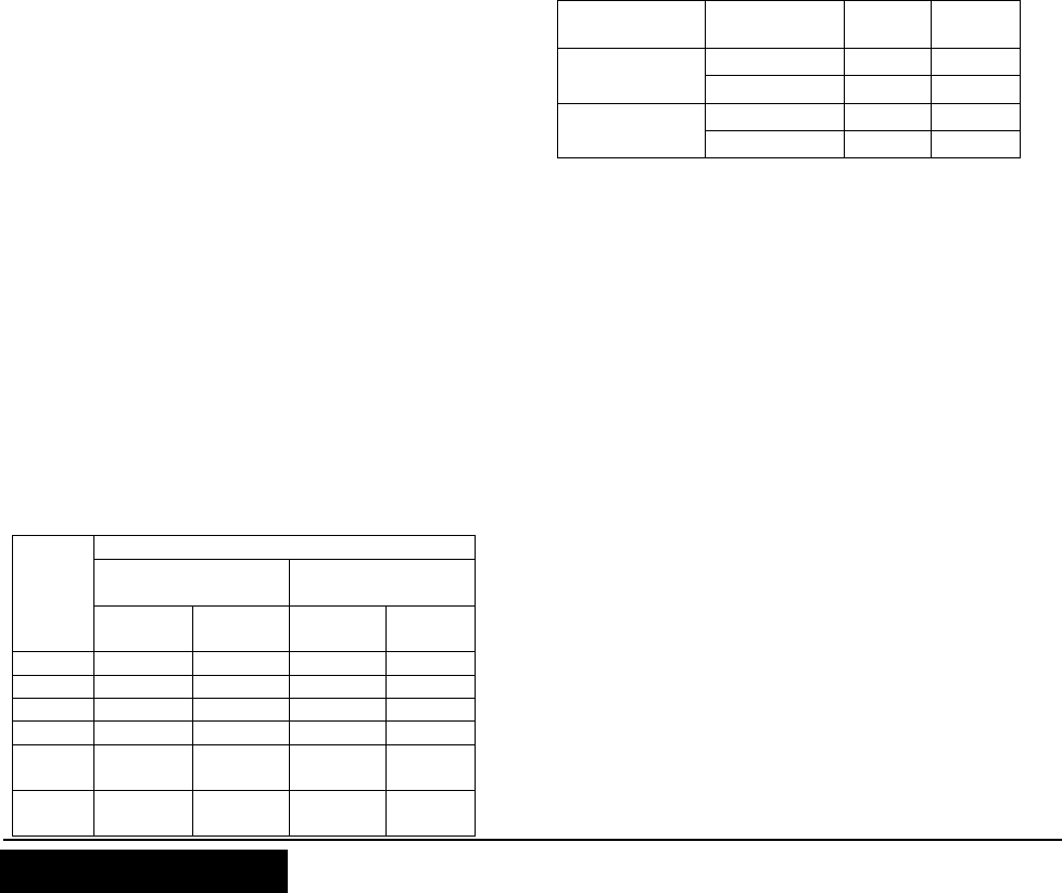
Backup Battery Options:
Maximum external devices current
(1)
9.6V 1800 mAh
Battery Pack
(2)
9.6V 2200 mAh
Battery Pack
(3)
Backup
period 1 battery
pack
(4)
2 battery
packs
(5)
1 battery
pack 2 battery
packs
(5)
4h 240mA 400mA 300mA 300 mA
8h 100mA 200mA 140 mA 260 mA
12h 55mA 120mA 80 mA 160 mA
24h 0mA 40mA 25 mA 70 mA
36h (no
backup) 15mA 10 mA 36 mA
48h (no
backup) 0mA 0 mA 18 mA
The backup periods, when the PowerMax Pro includes
internal PowerLink with 1 active camera, GSM and
proximity reader, with external load connected between
+12 / V+ terminal and GND terminal, is as follows:
Battery Pack
type Battery pack
Quantity Backup
period external
load
(1)
1 10h 30mA
9.6V 1800 mAh
(2)
2 20h 16 mA
1 12h 50 mA
9.6V 2200 mAh
(3)
2 24h 27 mA
1
Devices that are connected between +12 / V+
terminal and GND of PowerMax Pro, that includes
internal GSM and proximity reader.
2
9.6V 1800 mAh, rechargeable NiMH battery pack,
p/n GP180AAM8YMX, manufactured by GP.
3
9.6V 2200 mAh, rechargeable NiMH battery pack,
p/n GP220AAH8BMX, manufactured by GP.
4
Standard / UL installation
5
Extended backup installation
Maximum battery recharge time: 72 hours
Battery Test: Once every 10 seconds.
2.4 Communication
Built-in Modem: 300 baud, Bell 103 protocol
Data Transfer to Local Computer: Via RS232 serial port
Report Destinations: 2 central stations, 4 private
telephones, 1 pager.
Reporting Format Options: SIA, Pulse 4/2 1900/1400 Hz,
Pulse 4/2 1800/2300 Hz, Contact ID, Scancom.
Pulse Rate: 10, 20, 33 and 40 pps - programmable
Message to Private Phones: Tone or voice
Message to Pager: PIN No
."
Alarm Type
"
Zone No.
2.5 Physical Properties
Operating Temp. Range: 14°F to 120°F (-10°C to 49°C)
Storage Temp. Range: -4°F to 140°F (-20°C to 60°C)
Humidity: 85% relative humidity, @ 30°C (86°F)
Size: 10-13/16 x 8 x 2-1/8 in. (275 x 203 x 55 mm)
Weight: 990g (2.2 pounds) without batteries
Color: Silver
3
33
3.
..
. INSTALLATION
INSTALLATION INSTALLATION
INSTALLATION
3.1 Unpacking the Equipment
Open the cardboard packing box and check whether all
items have been included. If you find out that an item is
missing, contact your vendor or dealer immediately.
3.2 Supplying Power to the Unit
Enrolling the transmitting devices’ ID codes in the
PowerMax Pro memory will be easier if carried out before
actual installation, with all detectors and the control panel
on a work bench. It is therefore necessary to connect
power to the PowerMax Pro temporarily (see figure 3.1G).
Alternatively, you may power up from the backup battery,
as shown in figure 3.1C.
Disregard any “trouble” indications pertaining to lack of
battery or lack of telephone line connection.
3.3 System Planning & Programming
It pays to plan ahead - use the tables in appendices A and
B at the end of this guide to register the intended location
of each detector, the holder and assignment of each
transmitter and the control plan for the X-10 units.
Gather up all transmitters and detectors used in the
system and mark each one in accordance with your
deployment plan.
Program the system now as instructed in the
programming section.
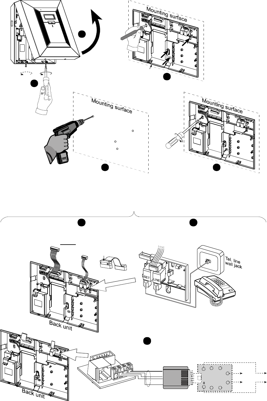
3.4 Mounting
Required tool: Philips screwdriver #2.
PowerMax Pro mounting process is shown in figure 3.1A -
3.1H.
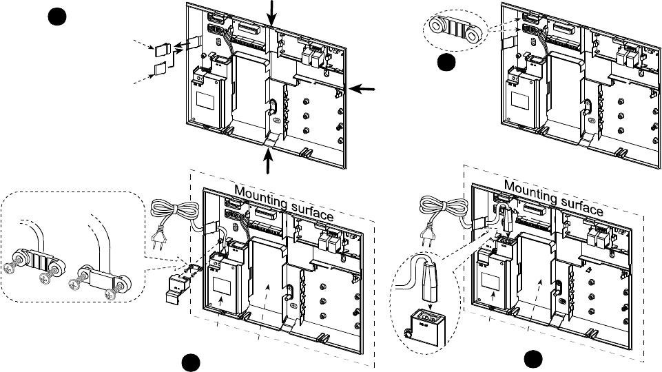
3.5 Wiring
Required tools: Cutter and slotted screwdriver - 3 mm
blade.
PowerMax Pro wiring is shown in figure 3.1B.
Extract the screw terminal blocks one by one and make
the necessary connections. When done, plug each
terminal block onto its PCB mounted pins.
DE5468IP 5
1
2
5
Fasten the back unit with 4 screws
4
Drill 4 holes and insert wall anchors
Release
screws
3
Back unit
Mark 4 drilling points on mounting surface
Figure 3.1A – Back Unit Mounting
1
Connect the receptacles of supplied flat cables
(2 - 5 cables according to options) to the back unit’s plugs.
The receptacles with strain relief clip are for the
front unit - do not connect to the back unit!
For all countries except north America:
Connect telephone cable to SET connector
and telephone line cable to LINE connector
(through the desired wiring cable entry).
2
Strain relief clip
PHONE WIRING
Wiring in north America only
3
RJ-31X
CORD
HOUSE
PHONES
RJ-31X
8-POSITION
RJ-31X PLUG
BROWN
GRAY
GRN
RED LINE
FROM
STREET
123
4
5
6
7
RJ-31X JACK
GREY
BROWN
GREEN
RED
6 DE5468IP
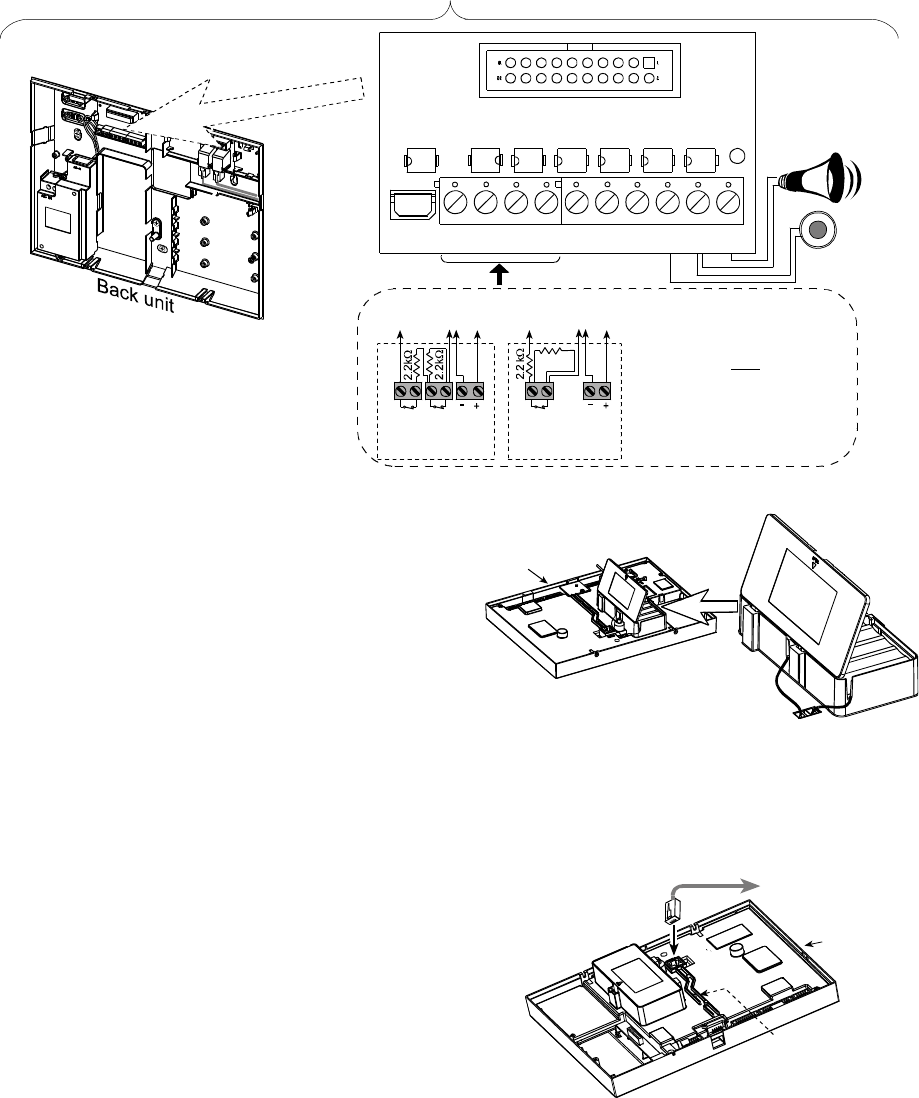
SITE
INTERNAL
SIREN OR
STROBE
SITE
EXT.
SIREN
SRN
EXT
+12VSRN
INT
PGM+12VGNDZONE
30 GND V+ZONE
29
ZONES
Note
Regarding zones 29 & 30, the Control
Panel “sees” a specific resistance
according to the event, as follows:
Normal (no alarm & no tamper): 2.2 kΩ
Alarm event: 4.4 kΩ
Tamper event: Infinite resistance
CONNECT WIRED DETECTORS AS FOLLOWS:
(*)
Power
ZONE 29 /
ZONE 30 GND
TAMP
N.C.
V+
(*)
Alarm
N.C.
ZONE 29 /
ZONE 30
Power
GND
2.2 kΩ
V+
Alarm
N.C.
Detector with
Tamper switch Detector without
Tamper switch
ZONES & SIRENS WIRING
Figure 3.1B - Wiring
Notes:
* Zone 29/GND and Zone 30/GND terminals can be
connected to a normally closed contact of a detector,
switch (for example a Tamper switch of any device), or
a pushbutton, via a 2.2 K
Ω
resistor. Such a resistor is
connected at the factory across both Zone 29/GND and
Zone 30/GND terminals. The resistors should remain
there if the terminals are not used. The V+ terminal
can be used to supply 12V (up to 36mA) to a detector
(if necessary).
** Both +12V terminals are identical (shorted together).
The EXT terminal can be used to trigger an external siren.
The INT terminal can be programmed for an "internal
siren" or "strobe" (see DEFINE OUTPUTS - DEFINE
INT/STRB in par. 4.8).
The +12V and "GND" terminals can be connected to
a siren (for constant DC power supply) – not
applicable in North America.
*** The X-10 jumper should be in 1-W position (for 1-way
power line interface unit) or in 2-W position (for 2-way
power line interface unit).
WARNING! When plugging terminals back into place, be
sure to align them carefully with the pins on the PCB.
Misaligned or reverse insertion of terminals may damage
internal PowerMax Pro circuits!
IMPORTANT! The terminals for internal and external
sirens are DC outputs intended for 12V sirens. Connecting
a loudspeaker to any of these outputs will cause a short
circuit and will damage the unit.
3.6 Backup Battery Insertion
Open battery compartment cover (see figure 3.1C). Insert
one 8-battery pack and connect its connector to the
PowerMax Pro receptacle.
For optional two 8-battery packs: Insert both battery
packs and connect one battery pack connector to either
receptacles and the second battery pack connector to the
other receptacle.
Front
unit
Figure 3.1C - Battery Insertion
3.7 X-10 Interface Module Connection
Connect the X-10 interface module connector to the
PowerMax Pro receptacle. Route the cable through the
cable channel and connect to the X-10 interface module,
via the back unit.
To X-10 interface
module via
the back unit
Cable
channel
6-position
RJ-11 plug Front
unit
Figure 3.1D - X-10 Interface Module Connection
3.8 Optional GSM Module Mounting
Plug in the GSM module and fasten it with the screw (see
drawing below).
Mount the optional GSM external antenna on the desired
site surface and connect its connector to the PowerMax
Pro as shown below).
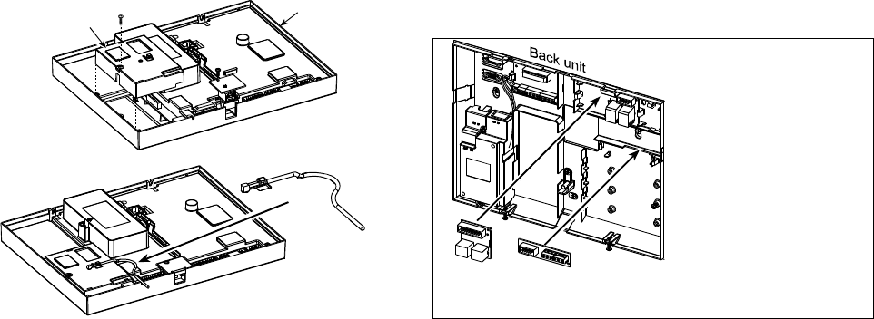
DE5468IP 7
GSM Front
unit
External GSM antenna cable
Figure 3.1E - Optional GSM Module Mounting
3.9 Additional Optional Module Mounting
The GSM/PL/PC is a dual RS-232 Module that permits any
two simultaneous device connections such as: internal or
external PowerLink, Local PC programming, external GSM
module.
Note: Connecting an internal and external GSM modules
simultaneously will disable both.
Note: The antenna(s) used for this transmitter must be
installed to provide a separation distance of at least 20 cm
from all persons and must not be co-located or operating
in conjunction with any other antenna or transmitter.
Press the GSM/PL/PC and AUDIO modules into the
marked locations (see figure 3.1F) until a click is heard.
12
1. GSM/PL/PC module
(dual RS-232
module).
2. Audio Module
Note: The Audio
Module terminal strip
should be wired to the
external Voice Box
terminal strip,
according to the
markings on both
terminal strips.
Figure 3.1F - Other Optional Modules Mounting
3.10 Power Cable Connection
Connect the power cable and close the control panel as
shown in figure 3.1G.
Socket-outlet shall be installed near the equipment and
shall be easily accessible.
8 DE5468IP
Safety
cover
Power cable clamp options
(*)
Power
supply
unit
For thin
cable For thick cable
(reversed clamp)
Extract either of
these cable clamps
for use in the next
step.
Thick cable entry: Pull out a
desired wiring plastic cap (1
of 4).
Small wiring plastic cap for
thin cable entry: Break the
smaller section of the wiring
plastic cap and insert the
wiring plastic cap back into its
place.
1
2
Enter power cable through the desired wiring channel (see step 1), route it to
the power supply unit and connect its 2 wires to the power supply terminal strip
with screwdriver. Fasten power cable by its clamp (see also step 2 - this clamp
can be reversed to fit thick/thin cable) and close the safety cover.
OPTIONAL PLUG-IN POWER SUPPLY
Connect the power connector (optional) to the power
supply unit.
34
(*)
Power
supply
unit
Figure 3.1G - Back Unit Power Cable Connection
* Do not route wiring in this area, to enable proper closure of the control panel.
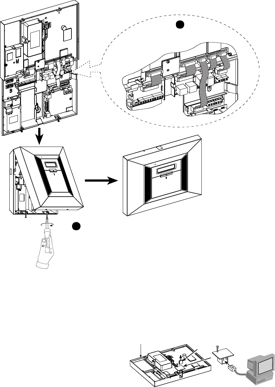
DE5468IP 9
Connect the flat cables in their respective
connectors (2 - 5, according to options).
1
Front
unit
Back
unit
2
Close the panel and
fasten the 2 screws.
Figure 3.1H - Final Closure
3.11
Installing
an
Optional X-10 Siren
If you need a “wireless” external siren, you may install an X-
10 siren module which is triggered by a signal transmitted
via the built-in electrical wiring of the protected site. This
siren can replace the regular external siren or complement it
without laying out additional wires. Of course, such a siren
can be used only in conjunction with an optional power-line
interface module.
The X-10 siren is ready to function upon connection to an
electrical power outlet, without re-programming the
PowerMax Pro. You only have to set the HOUSE CODE
and the UNIT CODE selectors on the X-10 siren as follows:
House Code: Set this selector to the letter that follows, by
alphabetical order, the letter that you programmed as a
house code for the protected premises. For example, if the
programmed house code is “J”, set the siren house code
selector to “K”.
Note: If the programmed house code letter is “P” (which is
the last programmable letter), select “A” for the siren.
Unit Code: The siren will function only if you set the unit
code selector to “1”.
3.12 Connecting to a Computer
The control panel can be equipped with an optional RS232
module for serial data interchange with a local computer. If
this module is not supplied, a special plastic cap blocks the
niche designed to accommodate the module.
Pull out the plastic cap (see figure 3.1I). Insert the RS-232
adapter and secure it with the screw. Break the smaller
section of the removed plastic cap and insert it back into its
place.
Plastic
cap
RJ-45 or
RJ-31X
(USA)
RS-232
adapter
Front Unit
Figure 3.1 I - Connecting to a Computer
3.13 Connecting to GSM Modem
The GSM unit enables the PowerMax Pro system to
operate over a cellular network. For details regarding the
GSM modem features and connections, refer to the GSM
Modem installation instructions.
10 DE5468IP
4
44
4.
..
. PROGRAMMING
PROGRAMMING PROGRAMMING
PROGRAMMING
4.1 INTRODUCTION
4.1.1 General Guidance
We recommend to program the PowerMax Pro on the work
bench before actual installation. Operating power may be
obtained from the backup battery or from the AC power supply.
The installer’s menu is accessible only to those who know
the installer’s 4-digit code, which is 9999 by factory default.
Note: Access to the installer menu, in PowerMax Pro that
has "User Permission" enabled (for example in UK) is
accessible only at the end of the user menu. This option can
be changed is necessary (see par. 4.4.36).
For PowerMax Pro that has 2 installer codes (not
applicable in UK), the default INSTALLER code is 8888
and the default MASTER INSTALLER code is 9999.
The following actions can be done only by using the
master installer code:
• Changing master installer code.
• Resetting the PowerMax Pro parameters to the default
parameters,
• Defining specific communication parameters, as
detailed in a note in figure 4.5.
Obviously, you are expected to use this code only once for
gaining initial access, and replace it with a secret code
known only to yourself.
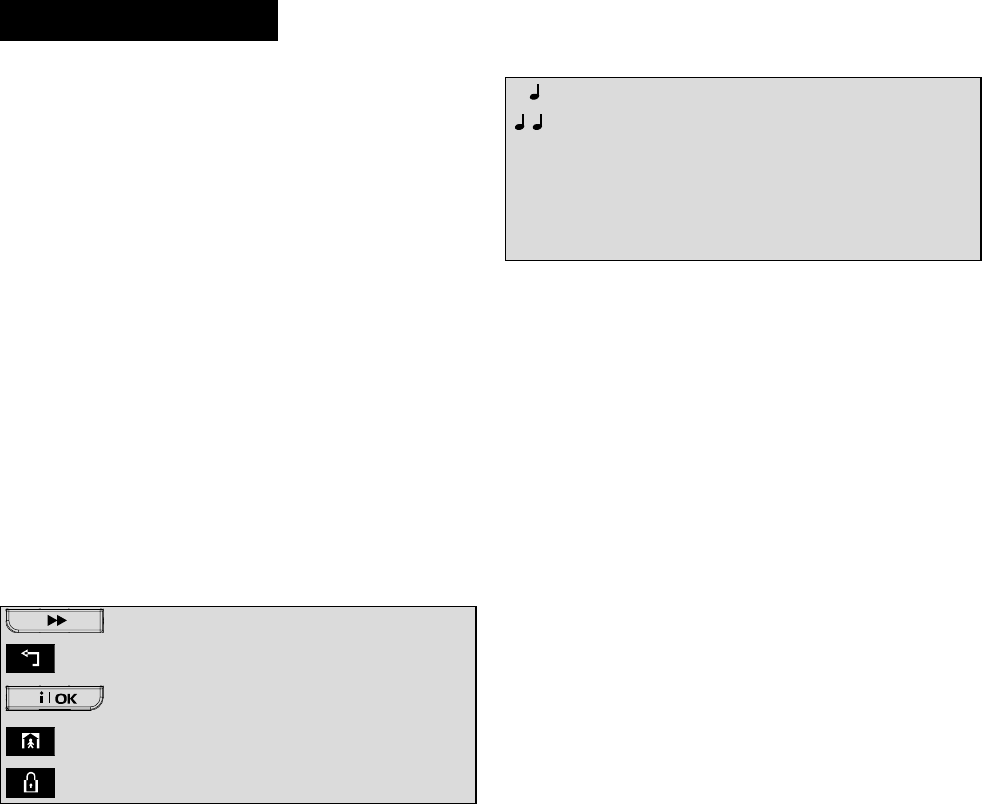
You will mainly use 5 control pushbuttons during the entire
programming process:
- to move one step forward in a menu.
- to move one step backward in a menu.
- to enter the relevant menu or confirm data.
- to move one level up in a menu.
- to return to the "OK TO EXIT" state.
The sounds you will hear while programming are:
- Single beep, heard whenever a key is pressed.
- Double beep, indicates automatic return to the
normal operating mode (by timeout).
☺
- Happy Melody (- - - –––), indicates successful
completion of an operation.
$
- Sad Melody (–––––), indicates a wrong move
or rejection.
4.1.2 Entering an Invalid Installer Code
If you enter an invalid installer code 5 times, the keypad
will be automatically disabled for 90 seconds and the
message WRONG PASSWORD will be displayed.
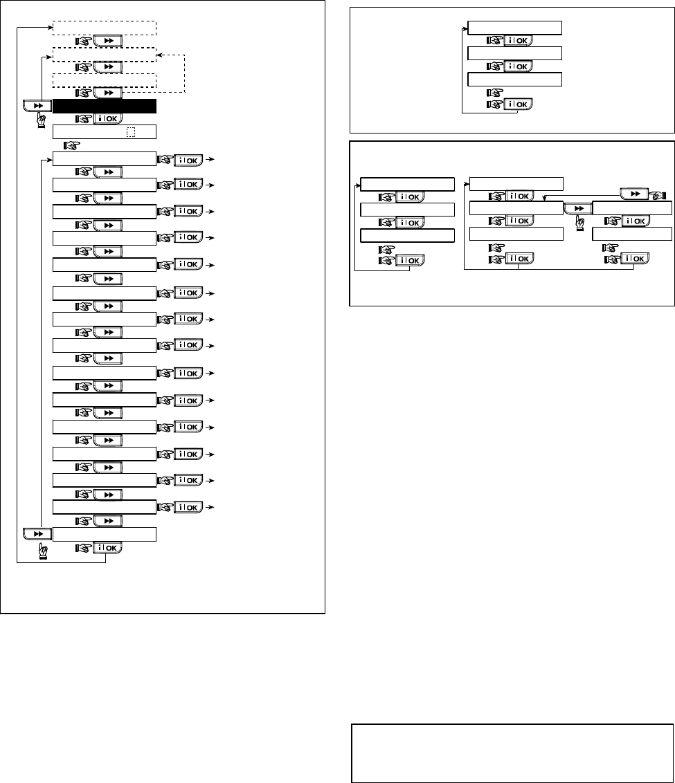
4.1.3 Installer’s Menu
The installer's menu is shown in figure 4.1a. The text in
rectangles represents the current PowerMax Pro display.
4.1.4 Setting a New Installer Code
To set an installer code, perform the actions that are
presented in figure 4.1b. When you are instructed to enter
code, enter a 4-digit code.
4.1.5 Setting a New Installer Code in
PowerMax Pro that has 2 Installer
Codes
For PowerMax Pro with 2 installer codes, INSTALLER
code (default 8888) and MASTER INSTALLER code
(default 9999), set new codes as shown in figure 4.1c.
For details regarding the different authorization levels
when logging in with installer code and master installer
code, refer to the note inside figure 4.5 (DEFINE COMM).
By using the master installer code, the menu enables
changing both master installer code and installer code.
By using the installer code, the menu enables changing
the installer code only.
DE5468IP 11
(See figure 4.9)
(See figure 4.3)
(See figure 4.4)
(See figure 4.5)
(See figure 4.8 )
(See chapter 7
in User Guide)
(See figure 4.2)
14. START UL/DL
13. SERIAL NUMBER
12. FACTORY DEFLT
11. USER SETTINGS
10. DIAGNOSTICS
9. DEFINE VOICE
8. DEFINE OUTPUTS
5. DEFINE COMM.
4. DEFINE PANEL
3. DEFINE ZONES
2. ENROLLING
1. NEW INSTL CODE
ENTER CODE
INSTALLER MODE
USER SETTING
NORMAL MODE
READY 00:00
[installer code]
(First display is READY
or NOT READY)
(See figure 4.10)
(See fig. 4.1b & 4.1c)
(See par. 4.12)
(Control Panel
serial number
display)
<OK> TO EXIT
(See section 4.14)
(See figure 4.6)
6. DEFINE GSM
(See figure 4.7)
7. DEFINE PWRLNK
(*)
(*) Applicable only when "USER PERMIT" function is enabled
(see par. 4.4.36 - USER PERMIT)
Figure 4.1a - Installer’s Menu
(See fig. 4.1a)
1. NEW INSTL CODE
NEW INST. CODE
INST. CODE xxxx
[code]
Figure 4.1b - Setting a New Installer Code (see note)
By using
INSTALLER CODE
INST. CODE xxxx
NEW INST. CODE
[code]
1. NEW INSTL CODE
(see fig. 4.1a)
(see fig. 4.1a)
[code]
1. NEW INSTL CODE
NEW MASTER CODE
MASTER CODE xxxx
[code]
INST. CODE xxxx
NEW INST. CODE
By using
MASTER INSTALLER CODE
Figure 4.1c - Setting a New Installer Code
in System with Inst. & Master Inst. Codes (see note)
Note:
Installer
Code should never be programmed as
“0000”. Doing so will lock the user out of the installer menu!
4
44
4.
..
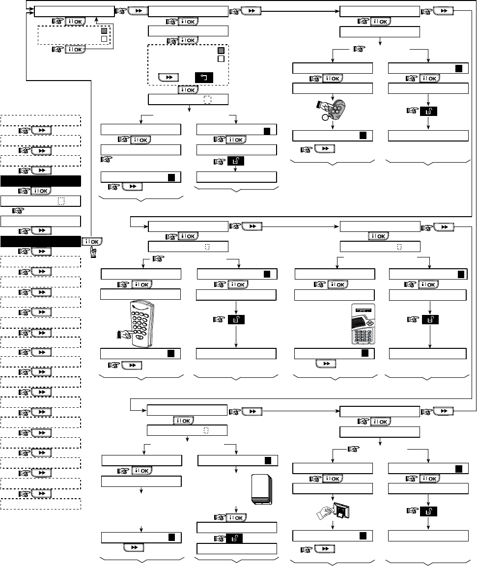
.2 ENROLLING WIRELESS DEVICES AND KEYFOB TRANSMITTERS
2 ENROLLING WIRELESS DEVICES AND KEYFOB TRANSMITTERS2 ENROLLING WIRELESS DEVICES AND KEYFOB TRANSMITTERS
2 ENROLLING WIRELESS DEVICES AND KEYFOB TRANSMITTERS
4.2.1 General Guidance
The ENROLLING mode has 5 sub-modes:
• ENROLLING TYPE (wireless devices)
• ENROLL WL (wireless devices) DEVICE
• ENROLL
KEYFOB (multi-button CodeSecure transmitters)
• ENROLL WL 1WAY KP (wireless commander MCM-140+)
• ENROLL WL 2WAY KP (wireless 2-way keypad MKP-150)
• ENROLL WL SIREN (wireless siren)
• ENROLL PROX TAG (proximity tag)
Before beginning, gather all the devices that you intend to
enroll and make sure they all have batteries installed.
Your control panel must recognize the unique identification
code (ID) of each such device in order to supervise them,
receive their signals and respond accordingly.
Attention! CodeSecure transmitters are mainly used for
arming/disarming and can not be enrolled to zones. For
enrolling to zones, use only non-CodeSecure
wireless devices.
12 DE5468IP
(First display is READY
or NOT READY)
READY 00:00
USER SETTINGS
NORMAL MODE
ENTER CODE
1. NEW INSTL CODE
2. ENROLLING
3. DEFINE ZONES
4. DEFINE PANEL
5. DEFINE COMM
[installer code]
INSTALLER MODE
ENROL WL 1WAY KP
8. DEFINE OUTPUTS
9. RECORD SPEECH
10. DIAGNOSTICS
11. USER SETTINGS
12. FACTORY DEFLT
13. SERIAL NUMBER
<OK> TO EXIT
14. START UL/DL
ENROLL WL DEVICE
ZONE No: 05
ZONE No: - -
[Initiate transmission)
ZONE No: 05
TRANSMIT NOW
ZONE No: 05
<OFF> TO DELETE
ZONE No: 05
[Zone No.] (e.g. 05)
(**)
(**)
Deleting a WL Device
Enrolling a WL Device
SET SENSITIV.
higher sensitivity
lower sensitivity
Select by
or
(***)
(****)
for next
enrolling action
%
%
[WL 1-way keypad
No. 1 to 8] (e.g. 5)
1way kp No :
1way kp No : 5 1way kp No : 5
(**)
1way kp No: 5
Enrolling a wireless
Commander MCM-140+
for next
enrolling action
<OFF> TO DELETE
key until
red LED
lights
TRANSMIT NOW
Deleting a wireless
Commander MCM-140+
1way kp No: 5
*
press
%
ENROL WL 2WAY KP
[MKP-150 No.
1 or 2] (e.g. 2)
%
2way kp No:
2way kp No : 2 2way kp No : 2
(**)
<OFF> TO DELETETRANSMIT NOW
Enrolling a wireless
keypad MKP-150
%
for next
enrolling action
%
ENROL WL SIREN
[WL siren No.
1 or 2] (e.g. 2)
%
SIREN No :
siren No : 2 siren No : 2
(**)
Momentarily press the
wireless siren self-test
button until a squawk is
heard (1 sec. approx.)
TRANSMIT NOW
Enrolling a
wireless siren
siren No: 2
%
for next
enrolling action
AWAY
2way kp No: 2
Deleting a wireless
keypad MKP-150
Press MKP-150
back tamper
switch once
(see MKP-150
inst. instructions)
2way kp No: 2
6. DEFINE GSM
7. DEFINE PWRLNK
<OFF> TO DELETE
Deleting a
wireless siren
siren No: 2
Open WL
siren cover
and remove
its battery
ENROLLING TYPE
normal enroll
by tamper
ENROLL KEYFOB
Keyfob No: 5
Keyfob No: -
TRANSMIT NOW
Keyfob No: 5
<OFF> TO DELETE
KEYFOB No: 05KEYFOB No: 05
[Keyfob No.]
(e.g. 5)
for next
enrolling action
Enrolling a Keyfob Deleting a Keyfob
(*)
(**)
(**)
(press any
key)
ENROLL PROX TAG
Tag No: 5
Tag No: -
PRESENT TAG
Tag No: 5
<OFF> TO DELETE
Tag No: 05Tag No: 05
(Prox tag No.)
(e.g. 5)
for next
enrolling action
Enrolling a Prox tag Deleting a prox tag
(*)
(**)
(**)
Present
tag
Figure 4.2 - Enrolling / Deleting Wireless Devices / Keyfobs / Wireless Commanders / Wireless Sirens
* Keyfob & proximity tags enrolling can be performed by the
installer or by the user (via USER SETTINGS menu).
** Black box in the display means that a device is
enrolled (the system has learned its ID). No black box
indicates that the device is not enrolled.
*** Initiate either normal transmission or the device
tamper function (see ENROLLING TYPE, Par. 4.2.2).
**** Select "higher" sensitivity for far wireless device,
"lower" for near devices.
4.2.2 Enrolling Type
Here you determine whether to enroll a wireless device by
normal transmission or by device Tamper function
(opening its cover). Options: normal, or by tamper.
4.2.3 Enroll/Delete Wireless Devices
Wireless devices include various PowerCode detectors
and hand-held transmitters.
DE5468IP 13
STOP
• Before enrolling, the lens at the front of PIR
and dual-technology sensors should be
masked to prevent inadvertent transmission.
• Make sure that magnetic contact transmitters are
together with their magnets, to prevent them from
sending out alarm transmissions.
To enroll / delete wireless devices, refer to figure 4.2.
4.2.4 Enroll/Delete Keyfob Transmitters
Keyfob transmitters are multi-button wireless CodeSecure™
transmitters. Eight system users use them for better,
quicker and safer control over various system functions.
To enroll / delete 1-way or 2-way keyfob transmitters, refer
to figure 4.2.
4.2.5 Enroll/Delete Wireless Commander
The Wireless Commander (MCM-140+) is a remote control
unit that enables the user to remotely control the system.
To enroll / delete up to 8 wireless commanders, refer to
figure 4.2 (Enroll WL 1-way KP).
4.2.6 Enroll/Delete 2-Way Keypad
The 2-way keypad, type MKP-150, enables the user to
remotely control the system and also to receive data from
the system (status, alarm and trouble data). To enroll up to
two 2-way keypads, refer to figure 4.2.
4.2.7 Enroll/Delete Wireless Siren
The wireless siren is a remote siren that is activated upon
predefined events by the PowerMax Pro system. To enroll
/ delete up to 2 wireless sirens, refer to figure 4.2.
4.2.8 Enroll/Delete Proximity Tags
Proximity tags enable authorized people to enter restricted
areas. Presenting valid proximity tag, while the system is
armed, causes the system to disarm. Presenting valid
proximity tag, while the system is disarmed, causes the
system to be armed in AWAY (optional HOME) mode. To
enroll / delete proximity tags, refer to figure 4.2.
4
44
4.
..
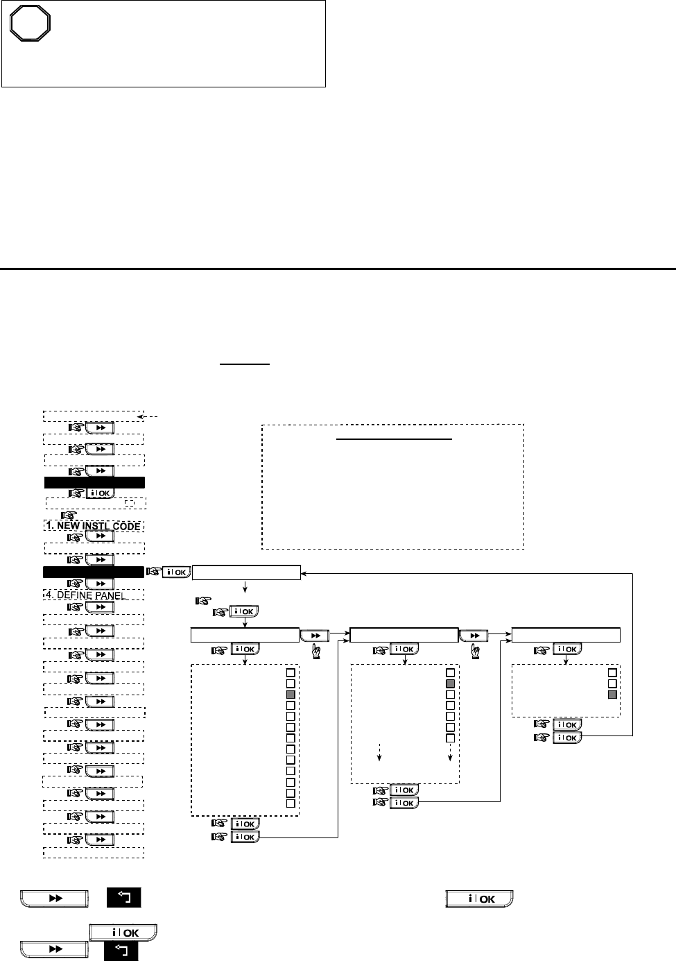
.3 DEFINING ZONE TYPES, NAMES & CHIME ZONES
3 DEFINING ZONE TYPES, NAMES & CHIME ZONES3 DEFINING ZONE TYPES, NAMES & CHIME ZONES
3 DEFINING ZONE TYPES, NAMES & CHIME ZONES
This mode allows you to assign one of 13 zone types to
each of the system's 30 (wireless & wired) zones. In
addition, it also allows you to assign a name to each zone
and determine whether the zone will operate as a chime
zone (only while the system is in the disarmed or Home
arming state). When a chime zone is triggered, chime
melody or zone name is heard (there are 3 selectable chime
modes - Melody chime, Zone Name Chime or Chime Off).
A list of factory defaults is printed on table 1. You may fill
out the blank columns even before you start and proceed
to program according to your own list.
Remember!
A delay zone is also a perimeter zone by definition.
Zone types are fully explained in Appendix D.
Selectable Zone Names
Dining room
Downstairs
Emergency
Fire
Front door
Garage
Garage door
Guest room
Hall
Kitchen
Laundry room
Living room
Master bath
Master bdrm
Office
Upstairs
Utility room
Yard
Custom 1
Custom 2
Custom 3
Custom 4
Custom 5
Attic
Back door
Basement
Bathroom
Bedroom
Child room
Closet
Den
31 zone names can be selected, 26 fixed names and 5
custom names (defined by the installer - see chap. 4.8):
Zxx: CHIME
Zone name-chime
(**)
ZONE No: - -
Zxx: TYPE -
[Zone No.] (e.g. 05)
1. Inter-follow
2. Perimeter Melody-chime
Chime off
Zxx: NAME - -
Attic
Back door
Basement
Bathroom
Bedroom
Child room
Closet
(*)
(*)
(*)
4. Delay 1
5. Delay 2
6. 24h silent
7. 24h audible
8. Fire
9. Non-alarm
10. Emergency
3. Perim-follow
(see list above)
11. Gas
12. Flood
13. Interior
(First display is READY
or NOT READY)
3. DEFINE ZONES
READY 00:00
NORMAL MODE
[installer code]
USER SETTINGS
ENTER CODE
2.
ENROLLING
5.
DEFINE COMM
INSTALLER MODE
<OK> TO EXIT
10. DIAGNOSTICS
8.
DEFINE OUTPUTS
9. DEFINE VOICE
11. USER SETTINGS
12. FACTORY DEFLT
13. SERIAL NUMBER
14. START UL/DL
6.
DEFINE GSM
7.
DEFINE PWRLNK
Figure 4.3 - DEFINE ZONES Flow Chart
* The currently saved option is displayed with a dark box at the right side. To review the options, repeatedly click
or button, until the desired option is displayed, then click (a dark box will be displayed
at the right side).
** Clicking the button in this location brings you to the same zone number that you are dealing with. Press
or to select the next zone.
14 DE5468IP
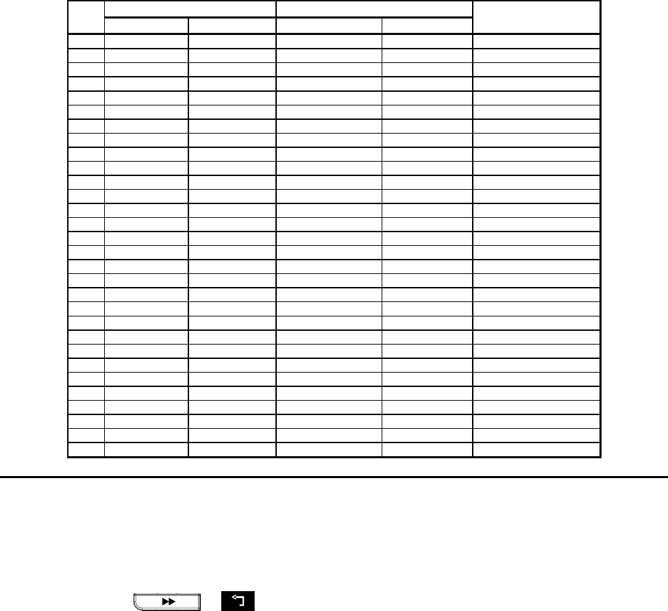
Table 1 - DEFAULT AND PROGRAMMED ZONE DEFINITIONS
Zone Zone Type Zone Name Chime (melody
No. Default
Programmed Default Programmed Zone Name or Off) (*)
1
Delay 1 Front Door
2
Delay 1 Garage
3
Delay 2 Garage Door
4
Perimeter Back Door
5
Perimeter Child Room
6
Interior Office
7
Interior Dining Room
8
Perimeter Dining Room
9
Perimeter Kitchen
10
Perimeter Living Room
11
Interior Living Room
12
Interior Bedroom
13
Perimeter Bedroom
14
Perimeter Guest Room
15
Interior Master Bedroom
16
Perimeter Master Bedroom
17
Perimeter Laundry Room
18
Perimeter Master Bathroom
19
Perimeter Basement
20
Fire Fire
21
Fire Fire
22
Emergency Emergency
23
Emergency Emergency
24
24 h / silent Basement
25
24 h / silent Office
26
24 h / audible Attic
27
24 h / audible Den
28
non-alarm Yard
29
non-alarm Hall
30
non-alarm Utility room
* Note: All zones are Off-chime by default. Enter your own choice in the last column and program accordingly.
4
44
4.
..
.4 DEFINING CONTROL PANEL PARAMETERS
4 DEFINING CONTROL PANEL PARAMETERS4 DEFINING CONTROL PANEL PARAMETERS
4 DEFINING CONTROL PANEL PARAMETERS
4.4.1 Preliminary Guidance
This mode allows you to customize the control panel and
adapt its characteristics and behavior to the requirements
of the particular user. An illustrated process is shown in
figure 4.4. In this illustration, each selected option is
displayed with a dark box at the right side. To review the
options, repeatedly click or button, until
the desired option is displayed, then click SHOW/OK button
.
4.4.2 Entry Delays 1&2
(fig. 4.4, location 01, 02)
Two different entry delays allow the user to enter the
protected site (while the system is in the armed state) via 2
specific doors and routes without causing an alarm.
Following entry, the user must disarm the control panel
before the entry delay expires. Slow-rate warning beeps
start sounding once the door is opened, until the last 10
seconds of the delay, during which the beeping rate
increases. Locations No. 1 (entry delay 1) and 2 (entry
delay 2) allow you to program the length of these delays.
Available options for each delay are:
00s
,
15s
,
30s
,
45s
,
60s
,
3m
and
4m
.
4.4.3 Exit Delay
(fig. 4.4 location 03)
An exit delay allows the user to arm the system and leave the
protected site via specific routes and doors without causing an
alarm. Slow-rate warning beeps start sounding once the
arming command has been given, until the last 10 seconds of
the delay, during which the beeping rate increases. Location
No. 3 allows programming of the exit delay length. Available
options are:
30s
,
60s
,
90s
,
120s
,
3m,
4m
.
4.4.4 Bell Time
(fig. 4.4, location 04)
Here you select the length of time the bell (or siren) is
allowed to function upon alarm. The bell time starts upon
activation of the siren. Once the bell time expires, the siren
is automatically shut down.
Available options are:
1
,
3
,
4
,
8
,
10
,
15
and
20
minutes.
4.4.5 Abort Time
(fig. 4.4 location 05)
Here you select the length of time allowed by the system to
abort an alarm (not applicable to alarms from FIRE, 24H
SILENT, EMERGENCY, GAS and FLOOD zones). The
PowerMax Pro is programmed to provide an “abort interval”
that starts upon detection of an event. During this interval,
the buzzer sounds a warning but the siren remains inactive
and the alarm is not reported. If the user disarms the system
within the allowed abort interval, the alarm is aborted.
Available options are:
00s
,
15s
,
30s
,
45s
,
60s
,
2m,
3m
,
4m
.
4.4.6 Alarm Cancel
(fig. 4.4, location 06)
Here you determine the ”cancel alarm” period that starts
upon reporting an alarm to the central station. If the user
disarms the system within that time period, a “cancel
alarm” message is sent to the central station.
Available options are:
1
,
5
,
15
,
60
minutes
,
4
hours
and
also
cancel inactive
.
4.4.7 Quick Arm
(fig. 4.4, location 07)
Here you determine whether the user will be allowed to
perform quick arming or not. Once quick arming is
permitted, the control panel does not request a user code
before it arms the system.
The two options are:
quick arm ON
and
quick arm OFF
.

DE5468IP 15
4.4.8 Bypass
(fig. 4.4, location 08)
Here you permit either manual bypassing of individual
zones (through the USER SETTINGS menu), or allow the
system to "force arm" (perform automatic bypassing) of
open zones during the exit delay. If desired, press the
arming key twice if you want to eliminate the delay beeps
that continue during a force arming. If a zone is open and
forced arming is not permitted, “NOT READY” is displayed
and the system does not arm (the “Sad Melody” will
sound). If "no bypass" is selected, neither manual
bypassing nor force arming is allowed.
Options:
manual bypass
,
force arm
and
no bypass
.
4.4.9 Exit Mode
(fig. 4.4, location 09)
Here you determine whether the exit delay will restart if the
exit / entry door is reopened before the exit delay expires.
Restarting the exit delay is helpful if the user re-enters
immediately after going out to retrieve an item that he left
behind. Three types of exit mode are available:
Restart Exit
- Exit delay restarts when the door is
reopened during exit delay. The restart occurs once only.
Off by door
- When the door is closed, the exit delay is
automatically terminated (even if the defined exit delay
was not completed).
Normal
- The exit delay is exactly as defined, regardless
of whether the door is open or closed.
4.4.10 Piezo Beeps
(fig. 4.4, location 10)
Here you determine whether warning beeps will sound or muted
during exit and entry delays. An additional option is to mute the
warning beeps only when the system is armed “HOME”.
Options:
enable beeps
,
off when home
and
disable beeps
.
4.4.11 Trouble Beeps
(fig. 4.4, location 11)
Under trouble conditions, the sounder emits a series of 3
short beeps once per minute. Here you determine whether
this special beeping sequence will be active, inactive, or
just inactive at night (the range of “night” hours is defined
in the factory). The 3 options are:
enable beeps
,
off at
night
(8 PM through 7 AM)
and
disable beeps
.
4.4.12 Panic Alarm
(fig. 4.4, location 12)
Here you determine whether the user will be allowed to
initiate a panic alarm by simultaneous pressing either the
two panic buttons (on the keypad / wireless commander)
or away + home (on a keyfob transmitter). Audible panic
activates the siren and simultaneously transmits a
message via telephone. Silent panic only transmits a
message via telephone. The options are:
silent panic,
audible panic
and
disable panic
.
4.4.13 Swinger Stop
(fig. 4.4, location 13)
Here you determine how many times each zone is allowed
to initiate an alarm within a single arming period (including
tamper & power failure events of detectors, PowerMax Pro
and wireless siren). If the alarms number from a specific
zone exceeds the programmed number, the control panel
automatically bypasses the zone to prevent recurrent siren
noise and nuisance reporting to the central station. The
zone will be reactivated upon disarming, or 48 hours after
having been bypassed (if the system remains armed).
Available options are:
shut after 1
,
shut after 2
,
shut
after 3
and
no shutdown
.
4.4.14 Cross Zoning
(fig. 4.4, location 14)
Here you determine whether cross zoning will be active or
inactive. Cross zoning is a method used to counteract
false alarms - an alarm will not be initiated unless two
adjacent zones are violated within a 30-second time limit.
This feature is active only when arming AWAY and only
with zone couples from zone No. 18 to 27 (18 and 19, 20
and 21, etc.). You may use any one of these zone couples
to create a “cross-zoned” area.
Note: If one of two crossed zones is bypassed (see Para.
4.4.8), the remaining zone will function independently.
Note: Every 2 crossed zones must be of the allowed zone
type (Interior, Perimeter, Perimeter follower).
The options are:
cross zone ON
and
cross zone OFF
.
Cross zoning is not applicable in Entry/ Exit zones and
24h zones (Fire, Emergency, 24h audible, 24h silent).
4.4.15 Supervision
(fig. 4.4, location 15)
Here you determine the time limit for reception of
supervision reports from various supervised wireless
devices. If any device does not report at least once within
the selected time limit, an “INACTIVITY” alert is initiated.
The options are:
1
,
2
,
4
,
8
,
12
hours
and
disable
.
4.4.16 NOT READY
(fig. 4.4, location 16)
Here you determine if the system will be NOT READY
status when there is a supervision failure. In the "in
supervision" mode, the system will be in NOT READY
status if during the last 20 minutes a supervision message
was not received. Options:
normal
and
in supervision
.
4.4.17 AUX Button A
(fig. 4.4, location 17)
Here you select the function of the AUX button on keyfob
transmitters and wireless commanders MCM-140+. Four
options are offered for each AUX button:
Status:
Pressing the AUX button will cause the control
panel’s voice module to announce the system status.
Instant:
Pressing the AUX button while the exit delay is in
progress will cause the system to arm “instant” (the entry
delay is canceled).
Skip exit delay:
Pressing the AUX button will immediately
cause the system to arm “instant”.
PGM / X-10:
Pressing the AUX button will activate the
PGM output or X-10 units (see further programming under
“DEFINE OUTPUTS”, par. 4.8).
4.4.18 AUX Button B 2-W-KF
(fig. 4.4,
location 18)
. Applicable only for 2-way keyfob MCT-237.
Same as 4.4.17 but for AUX button B.
4.4.19 Jam Detect
(fig. 4.4, location 19)
Here you determine whether jamming (interfering trans-
missions, on the radio channel used by the system) will be
detected and reported or not.
If a jam detection option is selected, the system does not
allow arming under the relevant jamming conditions.
Jam Detection Options
Option Detection and Reporting when
UL (20/20)
(USA standard) There is continuous 20 seconds of
jamming
EN (30/60)
(Europe standard) There is an accumulated 30 seconds of
jamming within 60 sec.
class 6 (30/60)
(British standard) Like EN (30/60) but the event will be
reported only if the jamming duration
exceeds 5 minutes.
Disabled
(no jamming detection and reporting).
4.4.20 Latchkey
(fig. 4.4, location 20)
Here you determine whether the system can be armed in
the latchkey mode. If the system is armed this way, a
“latchkey” message will be sent to specific telephones
upon disarming by a “latchkey user” (users 5-8 or keyfob
transmitters 5-8). This mode is useful when parents at
work want to be informed of a child’s return from school.
You can record a name for latchkey users.
The options are:
Latchkey ON
and
Latchkey OFF
.