Visonic PWRMAXPRO Security Control Panel User Manual DE5468IP2 w2002
Visonic Inc. Security Control Panel DE5468IP2 w2002
Visonic >
Contents
- 1. Users Manual Revised
- 2. Installars Guide Part 1 Revised
- 3. Installers Guide Part 2
- 4. Installers Guide Part 1 Revised
Installers Guide Part 2
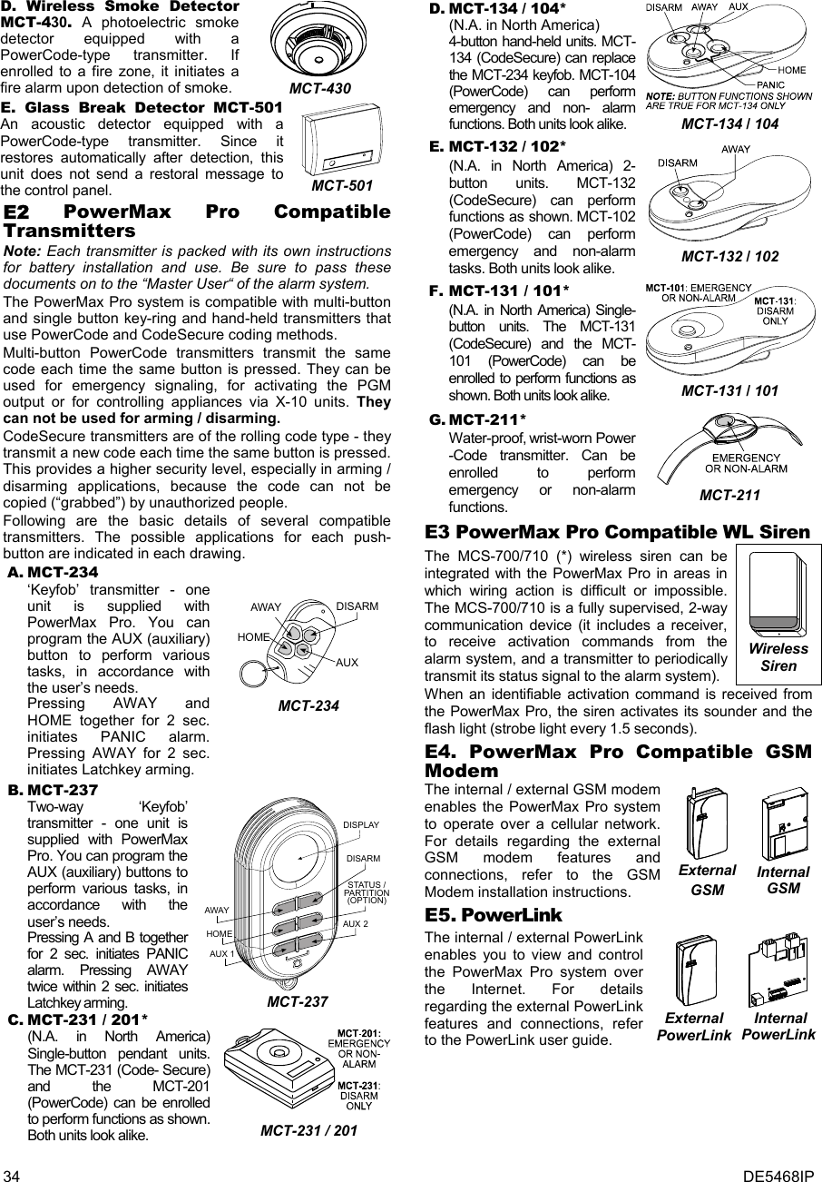
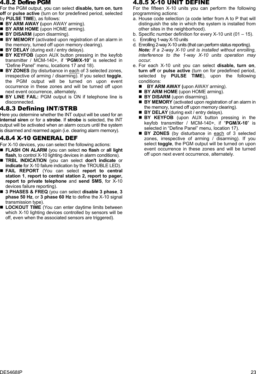
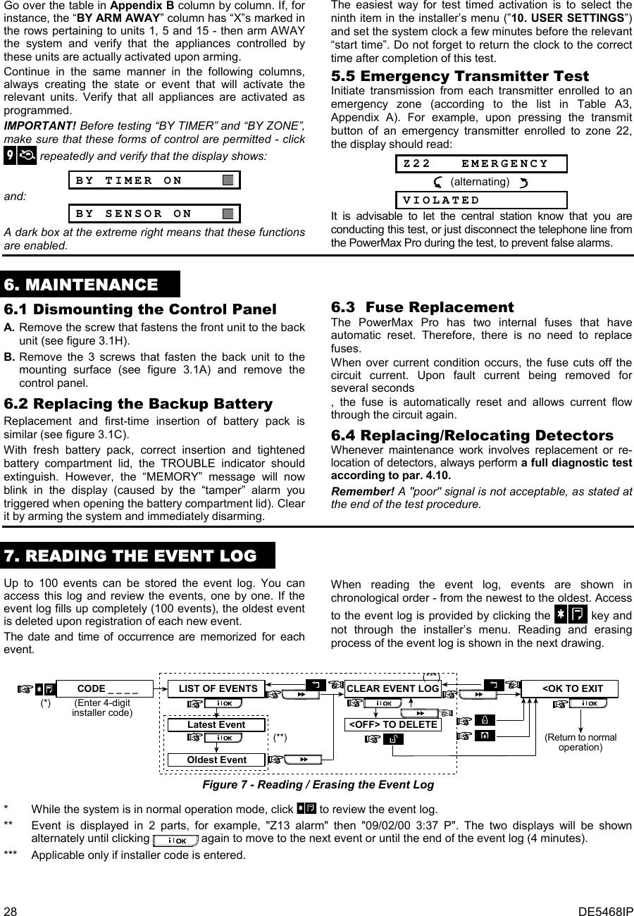
![16 DE5468IP 4.4.21 “Not Active” (fig. 4.4, location 21) Here you determine the time limit for reception of signals from sensors used to monitor the activity of sick, elderly or disabled people. If no device detects and reports movement at least once within the defined time limit, a “not-active” alert is initiated. Options: 3, 6, 12, 24, 48, 72 hours and no act disable. 4.4.22 Back Light (fig. 4.4, location 22) Here you determine whether the keypad back lighting will remain on at all times or will come on when a key is pressed and go off within 10 seconds if no further keystrokes are sensed. The two options are: always on and off after 10 s. 4.4.23 Duress (fig. 4.4, loc. 23) A duress alarm (ambush) message can be sent to the central station if the user is forced to disarm the system under violence or menace. To initiate a duress message, the user must disarm the system with the duress code (2580 by default). Here you can change the code digits or enter "0000" to disable the duress feature. The system does not allow the user to program the duress code saved in this memory location as an existing user code. 4.4.24 Piezo Siren (fig. 4.4, location 24) Here you determine whether the internal siren will sound or remain silent upon alarm (according to the user preference). Options: piezo siren on, piezo siren off. 4.4.25 Reset Option (fig. 4.4, location 25) (Not applicable in the USA) Here you determine whether the system can be rearmed (after an event) by the user or only by the installer. Options: user reset or engineer reset. If Engineer Reset is selected, the system can be rearmed only by the installer; by entering and exiting the installer menu, by entering and exiting the event log (see section 7), or by remote telephone. To perform Engineer Reset via the telephone, establish communication with the PowerMax Pro (see user guide, par. 6.3A, steps 1-5) and continue as follows: a. [*], [installer code], [#] b. Wait for 2 beeps c. [*], [1], [#] d. [*], [99], [#] 4.4.26 Tamper Option (fig. 4.4, location 26) Here you determine whether zone tamper will be reported or ignored. Available options are: zone tamper ON and zone tamper OFF. 4.4.27 Siren On Line (fig. 4.4, location 27) Here you determine whether the siren will be activated or not when the telephone line fails during system armed state. Available options are: enable on fail, disable on fail. 4.4.28 Memory Prompt (fig. 4.4, location 28) Here you determine whether the user will receive indication that an alarm has been activated. Available options are: enable and disable. 4.4.29 Disarm Option (fig. 4.4, location 29) Here you determine when it is possible to disarm the system: A. Any time. B. In AWAY mode, during entry delay, by using the PowerMax Pro keypad or wireless device (keyfob). C. In AWAY mode, during entry delay, by using a wireless device (keyfob) only (this is set as a default in UK to comply with DD423). D. During entry delay, or by using the PowerMax Pro keypad in AWAY mode. Options: any time, on entry all, on entry wireless, or entry + away kp. 4.4.30 Bell/Rep. Option (fig. 4.4, location 30) Here you determine whether an alarm will be initiated (siren / report) when there is a supervision / jamming failure during AWAY arming state. Available options are: EN standard and other. When "EN standard" is selected, if there is supervision / jamming failure during AWAY arming, the siren is activated and the events are reported as tamper events. When "Other" is selected, there is no such activity during AWAY arming. 4.4.31 Low-Bat Ack (fig. 4.4, location 31) Here you determine whether the user will hear or will not hear low battery sound when he tries to disarm the system with a keyfob whose battery voltage is low. Available options are: keyfob L-B on (the user has to acknowledge the keyfob low battery message) or keyfob L-B off (the user does not have to acknowledge the keyfob low battery message). 4.4.32 Screen Saver (fig. 4.4, location 32) Here you can determine that if no key is pressed during more than 30 seconds, the display will be “PowerMax” (to prevent possible intruder of knowing the system status). You can determine that normal display will return after pressing the button followed by entering user code (Refresh by Code) or after pressing any key (Refresh by Key). If Refresh by Key is selected, the first pressing of any key (except Fire and Emergency) will cause normal display return and the second press will perform the key function. Regarding the Fire and Emergency keys, the first key press will cause normal display return and also will perform the Fire/Emergency function. Options: scrn saver OFF, refresh by code, refresh by key. 4.4.33 Confirm Alarm (fig. 4.4, location 33) Here you determine that if 2 successive alarms will occur during a specific period, the second alarm will be considered as a confirmed alarm (for confirmed alarm reporting, see par. 4.5.12 REPORT CNF ALARM). Options: disable 30 min., 45 min., 60 min., or 90 min. 4.4.34 AC FAIL REP (fig. 4.4, location 34) Here you determine the time interval between AC power failure occurrence and the failure reporting. Options: 5 minutes, 30 minutes, 60 minutes or 180 minutes. 4.4.36 User Permission (fig. 4.4, location 36) Here you determine whether the access to the INSTALLER MODE requires user permission. If you select ENABLE, the installer mode will be accessible only through the user menu after entering the user code. Options: Enable, Disable.](https://usermanual.wiki/Visonic/PWRMAXPRO.Installers-Guide-Part-2/User-Guide-747809-Page-1.png)
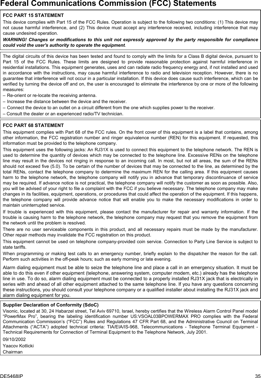
![DE5468IP 17 READY 00:00USER SETTINGSNORMAL MODEENTER CODE1. NEW INSTL CODE2. ENROLLING3. DEFINE ZONES5. DEFINE COMM[installer code]INSTALLER MODE05: ABORT TIME09: EXIT MODE13: SWINGER STOP17: AUX BUTTON Astatusinstant01: ENTRY DELAY 1 02: ENTRY DELAY 2 03: EXIT DELAY 04: BELL TIME06: ALARM CANCEL 07: QUICK ARMquick arm ONquick arm OFF08: BYPASSmanual bypassno bypassforce arm10: PIEZO BEEPS 11: TROUBLE BEEPS 12: PANIC ALARMcross zone ONcross zone OFF14: CROSS ZONING 15: SUPERVISIONsuperv time 1 hsuperv time 2 hsuperv time 4 hsuperv time 8 h16: NOT READYnormalin supervision4. DEFINE PANELentry dly2 00 sentry dly2 15 sentry dly2 30 sentry dly2 45 sentry dly2 60 sentry dly2 3 mentry dly2 4 mexit delay 30 sexit delay 60 sexit delay 90 sexit delay 120 sexit delay 3 mexit delay 4 mbell time 1 mbell time 4 mbell time 8 mbell time 10 mbell time 15 mbell time 20 mcancel time 1 mcancel time 5 mcancel time 15 mcancel time 60 mcancel time 4 hcancel inactiveenable beepsoff when homedisable beepsenable beepsoff at nightdisable beeps silent panicaudible panicdisable panicshut after 1shut after 2shut after 3no shutdownsuperv time 12 hdisablePGM / X-10entry dly1 00 sentry dly1 15 sentry dly1 30 sentry dly1 45 sentry dly1 60 sentry dly1 3 mentry dly1 4 mabort time 00 sabort time 15 sabort time 30 sabort time 45 sabort time 60 sabort time 2 mabort time 3 mrestart exitoff by doornormalbell time 3 mabort time 4 mNote: The currently savedoptions are displayed withdark box at the right side ofthe display. To review theoptions, repeatedly click or until thedesired option is displayed,then click OK (a dark boxwill be displayed at the rightside).Note: Force arm is notapplicable to the UK.6. DEFINE GSMinUSAinUSAinUSA inUSA8. DEFINE OUTPUTS9. DEFINE VOICE10. DIAGNOSTICS11. USER SETTINGS12. FACTORY DEFLT13. SERIAL NUMBER<OK> TO EXIT14. START UL/DL7. DEFINE PWRLNKskip exit delay19: JAM DETECTUL (20/20)EN (30/60)class 6 (30/60)disabled21: NOT ACTIVEno act time 3 hno act time 6 hno act time 12 hno act time 24 hno act time 48 hno act time 72 hno act disable22: BACK LIGHTalways onoff after 10 s23: DURESSduress code 2580(Change the code orenter 0000 to disableduress function)Note: Duress code is notapplicable to the UK.24: PIEZO SIRENpiezo siren onpiezo siren off25: RESET OPTIONuser resetenginner resetNot applicablein the USA26: TAMPER OPTIONzone tamper onzone tamper off27: SIREN ON LINEenable on faildisable on fail28:MEMORY PROMPTenabledisable29: DISARM OPTIONany timeon entry wrlessentry + awake kpon entry allNot applicablein the USAinUK30: BELL/REP. OPTEN standardother31: LOW-BAT ACKkeyfob L-B onkeyfob L-B off32: SCREEN SAVERscrn saver OFFrefresh by coderefresh by key34: AC FAIL REP5 minutes30 minutes60 minutes180 minutes36: USER PERMITDisableEnableinUK33: CONFIRM TIMEdisable30 minutes45 minutes60 minutes90 minutes20:LATCHKEYlatchkey onlatchkey off18: AUX B 2-W-KFstatusinstantPGM / X-10skip exit delay Figure 4.4 - DEFINE PANEL Flow Chart](https://usermanual.wiki/Visonic/PWRMAXPRO.Installers-Guide-Part-2/User-Guide-747809-Page-2.png)
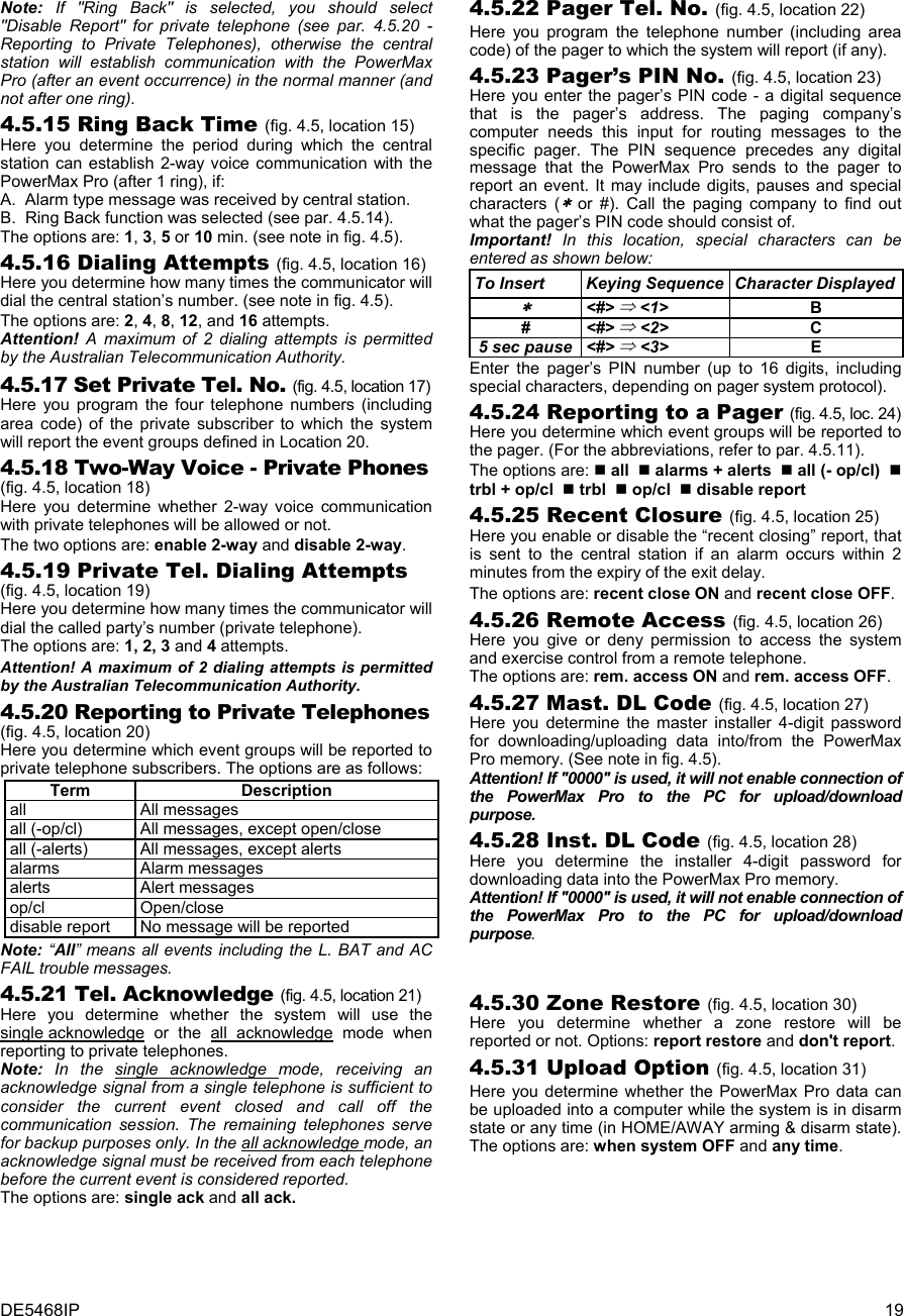
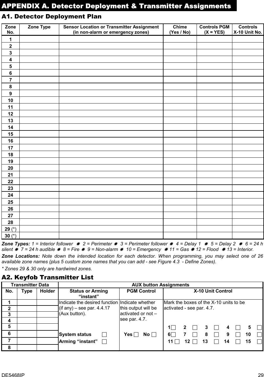
![18 DE5468IP 4.5 DEFINING COMMUNICATION PARAMETERS Preliminary Guidance This mode allows you to adapt the telephone communication parameters to the local requirements. Compatible central station receivers are: Osborne-Hoffman model 2000, Ademco Model 685, FBII Model CP220, Radionics Model D6500, Sur-Gard Model SG-MLR2-DG and Silent Knight Model 9500. IMPORTANT: In telephone / pager number locations and account number locations, you may be required to enter hexadecimal digits. In telephone number locations, these digits are used as codes to control the dialer: Hex.Digit Keying Sequence Code Significance A <#> ⇒ <0> Applicable only at the beginning of a number - the dialer waits 10 seconds or waits for dial tone, whichever comes first and then dials. B <#> ⇒ <1> Inserts an asterisk (J) C <#> ⇒ <2> Inserts a pound sign (#) D <#> ⇒ <3> Applicable only at the beginning of a number - the dialer waits 5 seconds for dial tone and goes on hook if none is received. E <#> ⇒ <4> Applicable only in the middle of the number - the dialer waits 5 seconds F <#> ⇒ <5> Not applicable in phone numbers To enter a series of digits, use the following keys: <Numeric keypad> - to enter the number - moves the cursor from left to right - moves the cursor from right to left - deletes everything after the cursor (to the right). 4.5.1 Autotest Time (fig. 4.5, location 01) Here you determine the time at which the telephone line will be tested and reported to the central station. 4.5.2 Autotest Cycle (fig. 4.5, location 02) Here you determine the time interval between consecutive telephone line test messages sent to the central station. The control panel performs this at regular intervals to verify proper communications. The options are: test every 1, 5, 7, 14, 30 days and test off. 4.5.3 Area Code (fig. 4.5, location 03) Here you enter the system tel. area code (up to 4 digits). 4.5.4 Out Access No (fig. 4.5, location 04) Here you enter the number that is used as a prefix to access an outside telephone line (if exists). 4.5.5 First Central Station Tel. (fig. 4.5, loc. 05) Here you program telephone number of the 1st central station (including area code, 16 digit max) to which the system will report the event groups defined in memory location 11 (see note in fig. 4.5). 4.5.6 First Account No. (fig. 4.5, location 06) Here you enter number that will identify your specific alarm control system to the first central station. The number consists of 4 or 6 hexadecimal digits (see note in fig. 4.5). 4.5.7 2ND Central Station Tel. (fig. 4.5, loc. 07) Here you program telephone number of the 2nd central station (including area code, 16 digit max) to which the system will report the event groups defined in memory location 11 (see note in fig. 4.5). 4.5.8 Second Account No. (fig. 4.5, loc. 08) Here you enter number that will identify your system to the 2nd central station. The account number consists of 4 or 6 hexadecimal digits (see note in fig. 4.5). 4.5.9 Report Format (fig. 4.5, location 09) Here you select the reporting format used by the control panel to report events to central stations (see note in figure 4.5). The options are: Contact-ID SIA 4/2 1900/1400 4/2 1800/2300 Scancom (see Appendix C - code lists). 4.5.10 4/2 Pulse Rate (fig. 4.5, location 10) Here you select the pulse rate at which data will be sent to central stations if any one of the 4/2 formats has been selected in Location 09 REPORT FORMAT (see note in fig. 4.5). The options are: 10, 20, 33 and 40 pps. 4.5.11 Reporting to Central Stations (fig. 4.5, location 11) (see note in fig. 4.5). Here you determine which types of event will be reported to central stations. Due to lack of space in the display, abbreviations are used: alarm is “alrm”, alert is “alrt” and open/close is “o/c”. The asterisk (J) is a separator between events reported to central station 1 and events reported to central station 2. Messages are divided by type into three groups: GROUP EVENTS REPORTED Alarms Fire, Burglary, Panic, Tamper Open/Close Arming AWAY, Arming HOME, Disarming Alerts No-activity, Emergency, Latchkey "Alarm" group has the highest priority and "Alert" group has the lowest priority. The selectable options are as follows: Plan name Sent to center 1 Sent to center 2 all -o/c J backup All but open/close All but open/close if center 1 doesn’t respond all J all All All all-o/c J all -o/c All but open/close All but open/close all –o/c J o/c All but open/close Open/close all (–alrt) J alrt All but alerts Alerts Alrm J all (–alrm) Alarms All but alarms Disable report Nothing Nothing all J backup All All if cent. 1 doesn’t respond Note: “All” means that all 3 groups are reported and also trouble messages - sensor / system low battery, sensor inactivity, power failure, jamming, communication failure etc. 4.5.12 Report CNF Alarm (fig. 4.5, location 12) Here you determine whether the system will report whenever 2 or more events (confirmed alarm) occur during a specific period (see par. 4.4.33 and note in figure 4.5). Available options are: enable report, disable report, enable + bypass (enabling report and bypassing the detector - applicable to PowerMax Pro that is compatible with DD423 standard). 4.5.13 Send 2WV Code (fig. 4.5, location 13) Here you determine whether the system will send two-way voice code to the central station (to turn the central station from data communication to voice communication state) by using pre-selected SIA or Contact-ID communication format only (see note in fig. 4.5). Options: send and don't send. 4.5.14 Two-Way Voice Central Stations (fig. 4.5, loc. 14). (See note in fig. 4.5). Here you select the timeout for 2-way voice communication with Central Stations, or enable the central station to ring back for 2-way voice function. This option is applicable only after reporting an event to the central station. (The central station person can press [3] for listen-in", [1] for "speak out" or [6] for listening and speaking). The options are: 10, 45, 60, 90 seconds, 2 minutes, ring back and disable (no two-way voice communication).](https://usermanual.wiki/Visonic/PWRMAXPRO.Installers-Guide-Part-2/User-Guide-747809-Page-3.png)
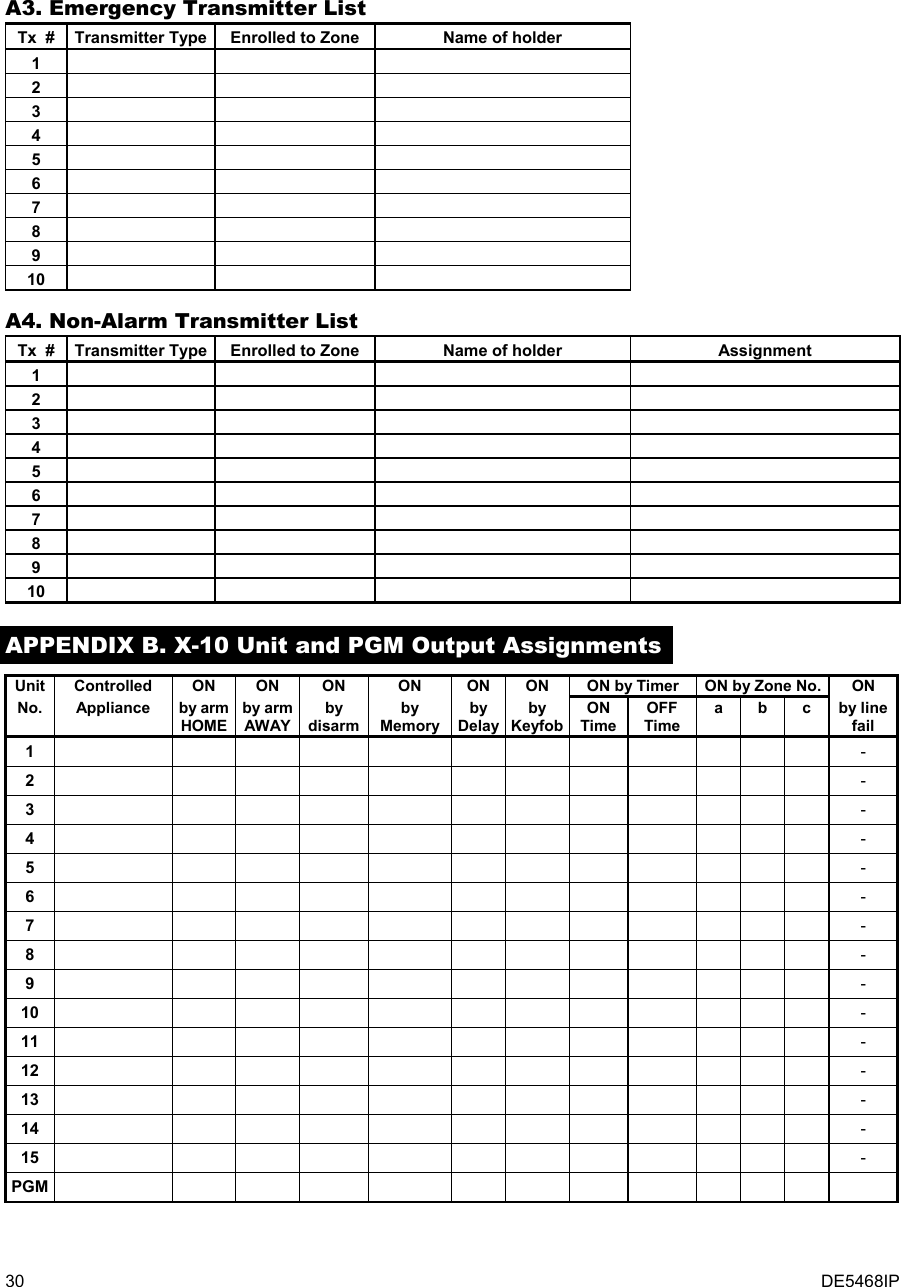
![20 DE5468IP (See note)NoteThe currently saved optionsare displayed with dark boxat the right side of the display.To review the options,repeatedly click or until the desired optionis displayed, then click OK (adark box will be displayed atthe right side).22: PAGER TEL #xxxxxxxxxxxxxxxx(Enter Tel. No.)23: PAGER PIN #xxxxxxxxxxxxxxxx(Enter PIN No.)24: REPORT PAGERallalarm +alertall (-op/cl)trbl + op/cltrblop/cldisable report13: SEND 2WV CODEsenddon’t send(See note)11: REPORT CNTRall - o/c * backupall * allall - o/c * all - o/call - o/c * o/call (-alrt) * alrtalrm * all (-alrm)disable reportall * backup(See note)07: 2ND CNTR TELxxxxxxxxxxxxxxxx(Enter Tel. No.)(See note)08: 2ND ACCOUNT #xxxxxx(Enter account No.)(See note)(See appendix - code list)09:REPORT FORMATcontact IDSIA4/2 1900/14004/2 1800/2300Scancom(See note)10: 4/2 PLS RATE10 pps20 pps33 pps40 pps(See note)21: TEL ACKNWLDGEsingle ackall ack20: REPORT PRVTallall (-op/cl)all (-alerts)alarmsalertsop/cldisable report19: PRVT ATTEMPTS1 attempt2 attempts3 attempts4 attempts18: VOICE PRVTenable two-waydisable two-way2 attempts4 attempts8 attempts12 attempts16 attempts16: DIAL ATTEMPTS(See note)1 minute3 minutes5 minutes10 minutes15: RINGBACK TIME(See note)time out 10 stime out 45 stime out 60 stime out 90 stime out 2 mring backdisable14: VOICE C.S.(See note)17: SET PRVT TEL#1st private tel#2nd private tel#3rd private tel#4th private tel#xxxxxxxxxxxxxxxx(Enter Tel. No.)12: RPRT CNF ALRMenable reportdisable report(See note)enable + bypass06: 1ST ACCOUNT #xxxxxx(Enter account No.)(See note)05: 1ST CNTR TELxxxxxxxxxxxxxxxx(Enter Tel. No.)(See note)02:AUTOTST CYCLE01: AUTOTEST TIMETest time 12:00 P(Enter test time)03:AREA CODE 04: OUT ACCESS Noxxxx(Enter tel. areacode, up to 4-digit)x(Enter ext. tel. lineaccess code, 1-digit)25: RECENT CLOSErecent cl. onrecent cl. off27: MAST. DL CODE26:REMOTE ACCESSrem. access onrem. access off28: INST. DL CODE 30: ZONE RESTOREreport restoredon’t report32: DIAL METHODtone (dtmf)pulse31: UPLOAD OPTIONwhen system OFFany time35: SYS INACT REPdisablerep after 7d34: UL/DL TEL #rep after 14drep after 30drep after 90dxxxxxxxxxxxxxxxx(Enter Tel. No.)33: LINE FAIL REPdon’t reportimmediately5 minutes30 minutes60 minutes180 minutestest every 1dtest every 5dtest every 7dtest every 14dtest every 30dtest OFFxxxxdownl. code AAAA(Enter 4-digit code)(”0000” is not valid)xxxxdownl. code BBBB(Enter 4-digit code)(”0000” is not valid)4. DEFINE PANEL5. DEFINE COMM.<OK> TO EXITUSER SETTINGSENTER CODE1. NEW INSTL CODE2. ENROLLING3. DEFINE ZONESINSTALLER MODE[inst. code] (see note)READY 00:00NORMAL MODENoteFor Control Panel that hasinstaller code & masterinstaller code, the followingfunctions are available only ifthe MASTER INSTALLERcode is entered:05: 1ST CNTR TEL06: 1ST ACCOUNT #07: 2ND CNTR TEL08: 2ND ACCOUNT #09: REPORT FORMAT10: 4/2 PLS RATE11: REPORT CNTR12: RPRT CNF ALRM13: SEND 2WV CODE14: VOICE C.S.15: RINGBACK TIME16: DIAL ATTEMPTS27: MAST. DL CODENot applicablein the USA38:AMBIENT LEVELApplicable for USA onlyhighlow Figure 4.5 - DEFINE COMM Flow Chart](https://usermanual.wiki/Visonic/PWRMAXPRO.Installers-Guide-Part-2/User-Guide-747809-Page-5.png)
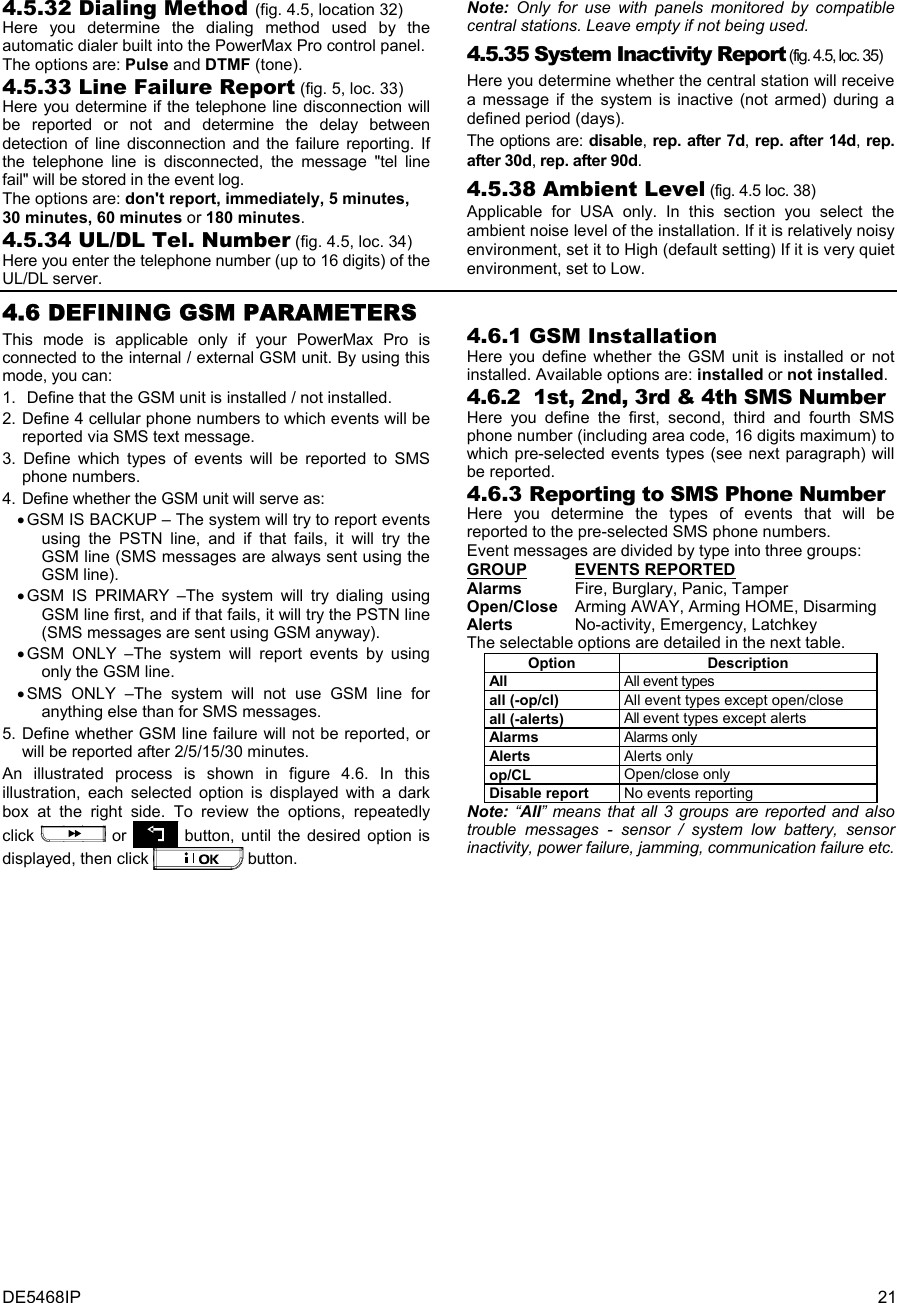
![22 DE5468IP <OK> TO EXIT5. DEFINE COMM.4. DEFINE PANEL3. DEFINE ZONES2. ENROLLING1. NEW INSTL CODEENTER CODEINSTALLER MODEUSER SETTINGSNORMAL MODEREADY 00:00[installer code]6. DEFINE GSM5. 4th SMS number1. GSM INSTALL 2. 1st SMS number 3. 2nd SMS number 4. 3rd SMS number6. REPORT SMS 7. GSM line failuredon’t report2 minutes8. GSM line purposeSMS onlyGSM is primaryGSM onlyallall (-op/cl)all (-alerts)alarmsalertsop/clInstalledNot installedxxxxxxxxxxxxxxxx(Enter GSM No.)xxxxxxxxxxxxxxxx(Enter GSM No.)xxxxxxxxxxxxxxxx(Enter GSM No.)xxxxxxxxxxxxxxxx(Enter GSM No.) 5 minutes15 minutes30 minutesdisable reportGSM is backup5. 4th SMS number 6. REPORT SMSallall (-op/cl)all (-alerts)alarmsalertsop/clxxxxxxxxxxxxxxxx(Enter GSM No.)disable report9. phones to CS 10. SMS to CSSMS as backupalwaysdisableuse phone 4use phones 3+4 Figure 4.6 - DEFINE GSM 4.6.4 GSM Line Failure Reporting Here you determine whether GSM network failure will be reported after 2 min., after 5 minutes, after 15 min., or after 30 minutes. Available options: don't report, 2 min, 5 min, 15 min, or 30 min. 4.6.5 GSM Line Purpose Define whether the GSM unit will serve as a backup for the regular telephone line, as a primary communication channel or as the only telephone channel or for sending SMS only. Available options are: GSM is backup, GSM is primary, GSM only or SMS only. 4.6.6 Phones to Central Station Here you determine the report format of the third and fourth pre-selected SMS phone numbers. Available options are: disable, use phone 4 or use phone 3+4. 4.6.7 SMS to Central Station Here you determine if an SMS message will always be reported to the central station via telephones 3 or 4, or only in case of a failure of a reported event via the PSTN line. Available options are: always or SMS as backup. Note: This feature is enabled only if use phone 4 or use phone 3+4 is selected in section 4.6.6. 4.7 DEFINING POWERLINK This mode enables you to enroll/delete the internal / external PowerLink and to enable/disable PowerLink communication failure reporting. The process is as follows:INSTALLER MODEUSER SETTINGSNORMAL MODEREADY 00:003. DEFINE ZONES2. ENROLLINGENTER CODE [installer code] 1. NEW INSTL CODE5. DEFINE COMM.4. DEFINE PANEL 7. DEFINE PWRLNK6. DEFINE GSM2: PWRLNK FAILUREdisable reportrep. of presence<OK> to enroll <OFF> to delete1: INSTALLDeleting PowerLinkEnrolling PowerLinkNote: Enrolling successis accompanied by aconfirmation sound. Figure 4.7 - DEFINE POWERLINK 4.8 DEFINING OUTPUT PARAMETERS 4.8.1 Preliminary Guidance This mode allows you: a. Events/conditions selection under which PGM (programmable) output and fifteen “X-10” devices will function. b. Function type selection for every X-10 unit and PGM output. c. General definitions selection for X-10 units. d. Selection of the internal siren or STROBE light (that will be activated according to system programming). e. Enrolling 2-way X-10 units. The process is shown in Fig. 4.8. Each selected option is displayed with a dark box at the right side. To review the options, repeatedly click or button, until the desired option is displayed, then click button.](https://usermanual.wiki/Visonic/PWRMAXPRO.Installers-Guide-Part-2/User-Guide-747809-Page-7.png)
![24 DE5468IP X-10 GENERAL DEFDEFINE INT/STRB X-10 UNIT DEFINESET HOUSE CODEdevice No. - -D- -: TYPE/FEATUREinternal sirenstrobeDEFINE PGM(enter device No.)house code =Ahouse code =Bhouse code =P(*)PGM (*)PGMdisableturn onpulse activeturn offDxx: BY DELAYdisableturn onpulse activeturn offdisableturn onpulse activeturn offtoggleDxx: BY KEYFOBdisableturn onpulse activeturn offdisableturn onpulse activeturn offdisableturn onpulse activeturn off(*)(**)PGMDxx: BY ZONESx - zone Z: _ _(ENTER ZONE NUMBERS)disableturn onpulse activeturn offtoggle(SELECT BY OR )a - zonec - zone b - zoneNote:PGM BY LINE FAIL function isapplicable for PGM only - not for X-10.by line fail noby line fail yesPGM: BY LINE FAIL(*)PGMDxx: BY DISARM(*)PGM (*)PGM (*)PGMDxx: BY ARM AWAY Dxx: BY ARM HOME Dxx: BY MEMORYpulse time 2spulse time 30spulse time 4mpulse time 2mDxx: PULSE TIME(*)PGM(First display is READYor NOT READY)READY 00:00NORMAL MODEUSER SETTINGSENTER CODE1. NEW INSTL CODE2. ENROLLING4. DEFINE PANEL[installer code]INSTALLER MODE3. DEFINE ZONES5. DEFINE COMMINSTALLER MODEDxx: LOCATIONSee detail “A”(next page)atticback doorbasementbathroomcustom 5(***)PLEASE WAITif alreadyenrolled(Turn X-10 to Learn mode)Enter learn ModeONE WAY UNIT TWO WAY UNIT<OK> to Enrolltest failenroll OKenroll failtest OKEnroll FAIL(Exit X-10 Learn mode)Exit Learn ModePLEASE WAIT<OK> to test<OFF> to Delete8. DEFINE OUTPUTS9. DEFINE VOICE<OK> TO EXIT6. DEFINE GSM7. DEFINE PWRLNKnot installed Figure 4.8 - Define Outputs Flow Chart * ** If PGM is selected, the letters "PGM" will be displayed instead of "Dxx". Upon selecting any one of the 3 options (zone a, b and c) you may enter a zone number and then select "disable", "turn on", "turn off", "pulse active" or "toggle".](https://usermanual.wiki/Visonic/PWRMAXPRO.Installers-Guide-Part-2/User-Guide-747809-Page-9.png)
![DE5468IP 25 *** The currently saved option is displayed with a dark box at the right side. To review the options, repeatedly click button until the desired option is displayed, then click (a dark box will be displayed at the right side). For zone name list, refer to paragraph 4.3 (DEFINE ZONE TYPES). Each X-10 unit has default zone name ( 01- front door, 02 - garage, 03 - garage door, 04 - back door, 05 – child room, 06 – office, 07 – dining room, 08- dining room, 09 – kitchen, 10 – living room, 11 – living room, 12 – bedroom, 13 – bedroom, 14 – guest room, 15 – master bedr). X-10 GENERAL DEFDEFINE INT/STRB X-10 UNIT DEFINEDEFINE PGMSelect “start”/”stop”andenter the desired time.report to PAGERdisableenableFAIL REPORTxxxx - 00:00 Astart - HH:MM Astop - HH:MM ALOCKOUT TIMEsend SMSdisableenabledisable 3 phase3 phase 50 Hz3 phase 60 Hz3 PHASE & FREQdisableenablerep to privateFLASH ON ALARMno flashall light flashreport to C.S. 1disableenablereport to C.S. 2disableenableTRBL INDICATIONdon’t indicateindicate Figure 4.8 - Detail A 4.9 DEFINE VOICE 4.9.1 Record Speech This mode allows you to record short-duration speech messages for the following purposes: • House identity is a message announced automatically when events are reported to private telephones. • 4 User Names can be recorded and assigned to users numbered 5-8. In case of event, the relevant user name will be added to the message that will be reported via the telephone. • 5 custom zone names can be recorded and assigned to specific zones. These names are useful if none of the 26 fixed zone names are found suitable for a certain zone (see fig. 4.3). The recording process is shown below. 4.9.2 Voice Box Mode This mode allows you to determine whether two-way voice communication is to be sounded either via an external speakerphone, via the PowerMax Pro, or via both. HOUSE IDENTITY USER #5 NAME USER #6 NAME USER #7 NAME USER #8 NAMERECORDING ENDEDTALK NOWRECORD A MESSAGE(e.g. “John’s house”)(*) (*)- don’t releaseRelease button [2] (**)Record users 5 - 8 names (for example, David, Rose, Mark, etc.).The process is identical to HOUSE IDENTITY recording process.USER TERM #1 USER TERM #2 USER TERM #3 USER TERM #4 USER TERM #5Record users terms 1-5 (e.g. Living room, Library, etc.), identical to HOUSE IDENTITY recording process.RECORD SPEECH9. DEFINE VOICE(see figure 4.1a)No Voice BoxVoice Box OnlyVoice Box MixedVOICE BOX MODE(*) RECORD MESSAGE is displayed momentarily. The dark square boxes slowly disappear, one by one, until end of recording time.(**) To check the recorded message, press the key and listen to theplayback. Figure 4.9 - Speech Recording Flow Chart 4.10 DIAGNOSTIC TEST This mode allows you to test the function of all protected area wireless sensors / wireless sirens / wireless keypads and to receive / review information regarding the received signal strength. Three reception levels are sensed and reported: Received Signal Strength Indication: Reception Buzzer Response Strong Happy Tune twice ( - - - –––– ) ( - - - ––––) Good Happy Tune ( - - - –––– ) Poor Sad tune ( –––––––– ) The diagnostic test process is shown in figure 4.10.](https://usermanual.wiki/Visonic/PWRMAXPRO.Installers-Guide-Part-2/User-Guide-747809-Page-10.png)
![26 DE5468IP When you are instructed to perform "walk test", walk throughout the site to check the detectors / sensors. When a detector/sensor is triggered into alarm, its name, number and the alarm reception level should be indicated (for example, "Bathroom", "Z19 strong") and the buzzer should sound according to the alarm reception level (1 of 3). IMPORTANT! Reliable reception must be assured. Therefore, a "poor" signal strength is not acceptable. If you get a "poor" signal from a certain detector, re-locate it and re-test until a "good" or "strong" signal strength is received. This principle should be followed during the initial testing and also throughout subsequent system maintenance. (Perform walk test)BATHROOMDIAG. TESTINGFRONT DOORZ1 POORZ19 STRONG(alternating for 5 sec.)LIVING ROOMZ2 OK(alternating for 5 sec.) Exampleof testresultdisplay (Each time the OK button is pressed,the next test result is displayed)(see figure 4.1a) 10. DIAGNOSTICS Exampleof testresultdisplay Exampleof testresultdisplayDIAG. TESTINGWL SENSORS TESTS1 CPUWL SIRENS TESTS1 CPU=STRONGWAITS2 CPUPLEASE WAIT...S2 CPU=STRONGWL KEYPADS TESTZ1 CPUZ1 CPU=STRONGWAITZ2 CPUPLEASE WAIT...Z2 CPU=STRONGNoteSTRONG/GOOD/POOR/“NOT OK” (with siren No.,S1 or S2 before) isdisplayed according to thewireless siren signalstrength).S1=siren 1. S2 = siren 2.CPU = Control Panel Unit = 2 way comm.NoteSTRONG/GOOD/POOR/“NOT OK” (with keypadNo., Z1 or Z2 before) isdisplayed according to thewireless siren signalstrength).Z1=keypad 1 Z2=keypad 2CPU = Control Panel Unit = 2 way comm. Figure 4.10 - Diagnostic Test Flow Chart 4.11 USER FUNCTIONS This mode provides you with a gateway to the user functions through the regular user programming menu. You may: • Program the 4 (private) telephone numbers • Program user codes • Enroll keyfobs • Enroll proximity tags • Select the voice option • Set the auto arm option • Set arming time • Set the squawk option • Set the system time and time format • Set the date and date format • Define PowerLink • Set the time scheduler Refer to the User Guide for detailed procedures. Caution! If after having programmed the user codes the system does not recognize your installer code, this indicates you must have programmed a user code that is identical with your installer code. If so, access the user menu and change the code that is identical with your installer code. This will re-validate your installer code. 4.12 RETRIEVING FACTORY DEFAULTS If you want to reset the PowerMax Pro parameters to the factory default parameters, you should enter the installer menu and perform the "FACTORY DEFLT" function, as described in the right side illustration. To get the relevant parameters defaults, contact the PowerMax Pro dealer. Note: For PowerMax Pro with 2 installer codes, INSTALLER code and MASTER INSTALLER code, only the master installer code enables to perform factory default function. 12. FACTORY DEFLT[installer code]<OK> to restoreENTER CODE:PLEASE WAIT ...Entering to/exit from the FACTORYDEFLT menu is shown in figure 4.1aThis is a brief display after which allthe factory defaults are retrieved. 4.13 SERIAL NUMBER The menu "13. SERIAL NUMBER" enables reading the system serial number for support purposes only. 4.14 CALLING UPLOAD/DOWNLOAD SERVER Note This option is only used during the installation of panels monitored by compatible central stations. This option allows the installer to initate a call to the upload/download server. The server uploads the PowerMax Pro configuration to its data base and can unload predefined parameters to the PowerMax Pro.](https://usermanual.wiki/Visonic/PWRMAXPRO.Installers-Guide-Part-2/User-Guide-747809-Page-11.png)
![DE5468IP 27 READY 00:00USER SETTINGSNORMAL MODEENTER CODE1. NEW INSTL CODE2. ENROLLING3. DEFINE ZONES5. DEFINE COMM[installer code]INSTALLER MODE4. DEFINE PANELCOMMUNICATING TEL # NOT DEFINEDDOWNLOADING DIAL ATTEMPT FAILDOWNLOAD OK DOWNLOAD FAILEDDisplayed duringdialing processDisplayed for halfa minute approx.accompanied by sad(failure) melodyIf UL/DL servertel. # was notdefined before(see par. 4.5.34)If UL/DL servertel. # is alreadydefined (seepar. 4.5.34)DialingOKDialingfailedDownloadOKDownloadfailedDisplayed duringdownload processDisplayed for halfa minute approx.accompanied by sad(failure) melodyDisplayed for halfa minute approx.accompanied by sad(failure) melodyDisplayed for halfa minute approx.accompanied by happy(success) melody8. DEFINE OUTPUTS9. DEFINE VOICE10. DIAGNOSTICS11. USER SETTINGS12. FACTORY DEFLT13. SERIAL NUMBER<OK> TO EXIT14. START UL/DL6. DEFINE GSM7. DEFINE PWRLNK Figure 4.14 – Start UL/DL 5. TESTING PROCEDURES 5.1 Preparations Make sure all windows and doors are closed. If all zones are secured (undisturbed), the display should read: READY HH:MM If the display is “NOT READY”, query the control panel by pressing the button repeatedly. The source(s) of the problem(s) will be displayed and read aloud. Take the necessary measures to eliminate the problem(s) before testing the system (see next paragraph). 5.2 Diagnostic Test To verify proper function of all detectors in the system, a comprehensive diagnostic test is required. To perform this test, refer to figure 4.10. 5.3 Keyfob Transmitter Test Initiate transmission from each transmitter enrolled as a keyfob unit (according to the list in Table A2, Appendix A). Use each transmitter to arm the control panel AWAY and immediately disarm it. Upon pressing the keyfob unit’s AWAY key, the ARM indicator should light. The display should respond as follows: ARMING AWAY PLEASE EXIT NOW The exit delay beeps will begin. Press the keyfob unit’s DISARM ( ) key. The ARM indicator should extinguish, the announcement “Disarm, ready to arm" should be heard and the display should revert to: READY HH:MM Test the AUX button in each keyfob in accordance with the information noted in Table A.2, Appendix A. Verify that the AUX button performs its duty as programmed. If the AUX (@) button is defined as “STATUS”, system status should be displayed and announced upon pressing the button. If the AUX (@) button is defined as “INSTANT”, press the AWAY button and then the AUX button. The response should be: ARMING INSTANT (alternating) PLEASE EXIT NOW and the exit delay beeps will start. Press the DISARM ( ) key immediately to disarm. If the AUX (@) button is programmed as “PGM / X-10” and permitted to activate one or several X-10 units, pressing (@) should activate the appliance controlled by the chosen X-10 unit(s). If the AUX (@) button is programmed as “PGM / X-10” and permitted to activate the PGM output, pressing (@) should activate the device wired to the PGM output. 5.4 Appliance ON/OFF Test The “X-10 unit assignment” information that you noted in Appendix B of this manual is very useful for this test.](https://usermanual.wiki/Visonic/PWRMAXPRO.Installers-Guide-Part-2/User-Guide-747809-Page-12.png)
![DE5468IP 33 D4. Flood Zone A flood zone is permanently active (a flood alarm is triggered regardless of whether the system is armed or disarmed). Upon detection of flood leak, the event is reported via the telephone line. D5. Gas Zone A gas zone is permanently active (a gas alarm is triggered regardless of whether the system is armed or disarmed). Upon detection of gas leak, the event is reported via the telephone line. D6. Interior Zone Interior zones are zones within the protected premises that have nothing to do with perimeter protection. Their most important feature is that they allow free movement within the protected area without initiating an alarm, provided that the system is armed in the "HOME" mode. People can therefore stay at home and move about freely, as long as they do not disturb a PERIMETER zone. Once the system is armed in the AWAY mode (all zones are protected), interior zones will initiate an alarm if violated. D7. Interior Follower Zones "Interior Follower" zone is a zone that is located between entry/exit zone and the alarm system control panel. This zone is temporarily ignored by the alarm system during entry/exit delay periods, to enable you to walk (without causing an alarm) in front of a motion detector that is associated with the Interior Follower zone, after you enter through an entry zone on the way to the control panel, or when leaving the protected premises after system arming. D8. Non-Alarm Zones A non-alarm zone does not directly participate in the alarm system. Its main use is to perform auxiliary remote control tasks such as opening/closing a gate, activating/deactivating courtesy light and similar applications. No alarm, silent or otherwise, is associated with a non-alarm zone. For remote control of electrical devices, you can define the desired number of non-alarm zones and enroll a portable transmitter or a wireless device (detector) to this type of zone. Then, you must ensure that these zones are permitted to control the PGM output, or the X-10 units or both (see par. 4.8). Next, you can select the zones (3 at most) that will control each output. The outputs, in turn, will control the external electrical devices. Note: A device control can also be carried out by holders of all keyfob transmitters, by pressing the AUX [M] button. This method will work provided that you programmed the [M] button for PGM/X-10 control (see Par. 4.4.17 and 4.4.18), and that you programmed the PGM output and the X-10 units to be controlled by keyfob transmitters (see par. 4.8). D9. Perimeter Zones Perimeter zones rely on detectors designed to protect doors, windows and walls. An immediate alarm is initiated when such a zone is violated by opening the door/window or by trying to break the wall. D10. Perimeter Follower Zones A non-entry/exit zone, typically a perimeter zone located on an entry/exit path, that is treated as an entry/exit zone during an entry/exit time. D11. 24-Hour Zones 24 hour zones are mainly used for PANIC buttons, perimeter detectors and anti-tamper protection. They therefore trigger an alarm in both armed and disarmed states. • 24 Hour Zone - Silent. - Upon detection, this zone initiates a silent alarm, meaning that the sirens do not function. Instead the PowerMax Pro dials telephone numbers and reports the event to central stations and/or to private telephones, as programmed. • 24 Hour Zone - Audible. - Upon detection, this zone initiates a siren alarm. The PowerMax Pro also dials telephone numbers and reports the event to central stations and/or to private telephones, as programmed. APPENDIX E. PowerMax Pro Compatible Devices E1. PowerMax Pro Compatible Detectors Each detector compatible with the PowerMax Pro system is packed with its own installation instructions. Read them carefully and install as indicated. A. PIR Motion Detectors The wireless passive infrared (PIR) motion detectors used in the system are of the PowerCode type. The PowerMax Pro is capable of “learning” each detector’s identification code and linking it to a specific zone (see par. 4.3 in this Guide). Some units are shown below: NEXT® K9-85 MCW MCPIR-3000 or K-940 MCW DISCOVERY K9-80/MCW Note: K-940 MCW, Discovery K9-80/MCW and NEXT® K9-85 MCW are pet immune units. In addition to its unique 24-bit identification code, each detector transmits a message, containing status information: • The detector is in alarm (or not). • The detector is being tampered with (or not). • The battery voltage is low (or normal). • “This is a supervisory message”. If any of these detectors detects motion, it sends out a message to the alarm control panel. If the system is in the armed state, an alarm will be triggered. B. Magnetic Contact Transmitter MCT-302 is a PowerCode magnetic-contact transmitter used to detect the opening of a door or a window. The alarm contacts are closed as long as the door or window remains closed. MCT-302 The unit has an extra alarm input that acts as if it were a separate wireless transmitter. It sends (or does not send) a “restored to normal“ message to the alarm system, depending on the setting of an on-board “DIP” switch. The “restore” message informs you, through the control panel’s display, whether the door or window is open or closed. C. MCT-100 Wireless Adapter for Wired Detectors MCT-100 is a PowerCode device used mainly as a wireless adapter for 2 regular magnetic switches installed on 2 windows in the same room. It has two inputs, behaving as separate wireless transmitters with different PowerCode IDs. Each input sends (or does not send) a “restored“ message to the alarm system, depending on the setting of an on-board “DIP” switch. MCT-100](https://usermanual.wiki/Visonic/PWRMAXPRO.Installers-Guide-Part-2/User-Guide-747809-Page-18.png)