Vivosonic V50 VIVOLINK User Manual USER S MANUAL
Vivosonic, Inc. VIVOLINK USER S MANUAL
Contents
- 1. USERS MANUAL 1
- 2. USERS MANUAL 2
USERS MANUAL 2
Chapter 5 User's Manual Integrity General Operating Procedures
Preparing for a test 11049 Rev.2 73
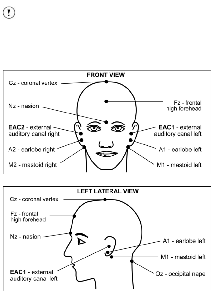
Recommended electrode placement
NOTE
The patient’s skin must be prepared before the snap electrode pads can
be attached.
The following electrode placement configurations are recommended for the Amplitrode®,
which is optimized for a single-channel recording (Figure 61).
[Hall, 1990], [Hall, 1997], [Stapells, 2001]
Figure 61 Typical electrode placement diagram - front view
Figure 62 Typical electrode placement diagram - left lateral view
The recommended electrode sites are:
• Non-inverting electrode (active or positive): High forehead (Fz).
General Operating Procedures User's Manual Integrity Chapter 5
74 11049 Rev.2 Preparing for a test
• Inverting electrode (reference or negative): Left mastoid (M1), right mastoid
(M2), left earlobe (A1), right earlobe (A2); or nape (Oz).
• Amplitrode® (ground): low forehead (Fpz); nasion (N); opposite ear lope; or
opposite ear canal.
ATTENTION
To ensure reliable waveforms, the electrode clips must be connected
securely to the snap electrode pads.
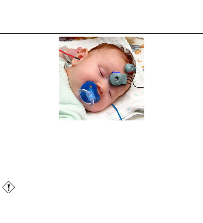
Figure 63 Amplitrode® and Electrode Clips Placement (shown on an infant)
Preparing the Patient
Skin preparation
The patient’s skin must be clear and free of damage, malformations, or disease before
starting the test.
CAUTION
Patients may incur additional skin damage.
If the patient’s skin has wounds, scratches, bruises, or any other signs of
damage, malformation, or disease do not proceed with the skin
preparation or the placement of the electrodes.
1. Visually inspect the area of skin where the electrodes will be placed. If the skin is
damaged, do not proceed with the test.
2. Carefully remove oil, dead skin particles, or foreign matter from the skin areas
that will be in contact with the snap electrode pads.
3. Remove excessive moisture with a dry cotton ball or gauze pad.
4. Apply abrasive skin preparation cream or jelly on the cleaned skin surface,
following the manufacturer’s instructions for use.
5. Remove excessive abrasion cream or jelly with a cotton ball or gauze pad.
Chapter 5 User's Manual Integrity General Operating Procedures
Preparing for a test 11049 Rev.2 75
Application of the electrodes
Vivosonic recommends starting by connecting the Amplitrode® to the ground electrode
connection. Once secure, connect the electrode clips to the snap electrode pads. The
non-inverting (+) and inverting (-) electrodes are distinguishable by the “+” and “-”
symbols located on the clips’ upper surface.
6. Visually inspect the pouch with single-use electrode pads and check the
expiration date indicated on the back of the pouch in the following format “YYYY
– MM” (year – month), for example “2005 – 05).
7. Remove the single-use snap electrode pads from the plastic base and paste
them on the prepared areas of the patient’s skin. Refer to Figure 61 for details on
the recommended locations of the electrodes.
8. Hold the electrode clip with two fingers so that the index finger is in the Holding
Groove and the thumb depresses the Electrode Release Button.
9. Snap the Amplitrode® and the two electrode clips onto the electrode pads. When
the electrode release button is let go, the electrode will be securely clipped to the
electrode pad.
10. Check that the electrode is securely seated on the electrode pad.
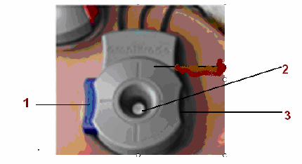
Figure 64 Amplitrode®
(1 – Electrode Release Button 2 – Electrode Clip 3 – Holding Groove)
Checking electrode contact quality
A unique feature of the Integrity™ system is its ability to monitor the contact quality
during ABR data collection. It checks the electrodes continuously to monitor for any
changes of quality of its connection to the patient during the test procedure.
Contact quality monitoring start when the electrodes are attached to the patient. There
are two places to monitor the contact quality, on the VivoLink™ and on the Test screen.
Contact Quality on the VivoLink
The easiest way of checking the contact quality is to monitor the VivoLink™ contact
quality mismatch LED. It is located on the front panel of the VivoLink™ (Figure 5). This
LED indicates a poor connection between the electrode and the patient from either the
inverting or non-inverting electrodes.
When the LED is not lit there is no problem indicated.
An Amber lit LED indicates the inverting (-) electrode has poor contact with the patient.
A Green lit LED indicates the non-inverting (+) electrode has poor contact with the
patient.

General Operating Procedures User's Manual Integrity Chapter 5
76 11049 Rev.2 Preparing for a test
Contact Quality from the Test screen
The LED indicators represent the quality of the contact between the inverting or non-
inverting electrode and the patient’s skin. When the centre LED is lit, shown lit in Figure
28, there is no problem indicated. This is the optimal display representing a good contact
quality.
When the left (amber) LED indicator is lit this indicates a problem between the connection
of the inverting (-) electrode and the patient. When the right (green) LED indicator is lit
this indicates a problem between the connection of the non-inverting (+) electrode and
the patient. Refer to Figure 29.
Correcting poor contact quality
A poor connection will affect the results. When the contact quality of one active electrode
is poor, follow these steps:
1. Wait for a couple of minutes – the contact quality will often decrease to an
acceptable level on its own.
2. If the levels do not change, disconnect the non-functioning electrode (left LED’s
for inverting (-), right LED’s for non-inverting (+)). Remove the electrode clip from
the snap electrode pad and repeat the skin preparation procedure.
3. Apply a new snap electrode pad and reconnect the electrode clip.
4. Repeat contact quality checking.
ATTENTION
Identifying poor contact quality for two electrodes
If both electrodes have poor contact quality the LED may show only one
electrode as being poor or the LED may erratically indicate one electrode
and then the other electrode as poor.
If after fixing one electrode there is still a problem it is recommended to
fix the other electrode before assuming a problem with the Amplitrode®.
Choose a transducer
To perform an Air-conduction Test, use the ER-3A Earphones. To perform a Bone-
conduction Test, select the B-71 Bone Conductor.
Chapter 5 User's Manual Integrity General Operating Procedures
Preparing for a test 11049 Rev.2 77
ATTENTION
To perform an ABR test with ER-3A earphones the protocol selected
must be configured to use the ER-3A Transducer Type. If it is not the
stimuli will not be transmitted through the earphones.
To perform ABR test with B-71 Bone Conductor the protocol selected
must be configured to use the B-71 Transducer Type. If it is not the
stimuli will not be transmitted through the bone conductor.
ER-3A Earphones
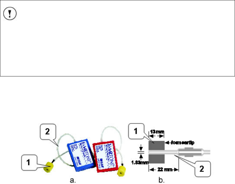
To perform ABR or data collection via air conduction, insert ER-3A earphones (Figure
65).
Figure 65 ER-3A earphones (a) and their foam ear tip dimensions (b)
1 – Foam ear tip 2 – silicone air-conducting tube inside the foam ear tip
If earphones are chosen for testing do the following:
6. Inspect the patient’s ear canal, preferably with an otoscope (not
included) for obstructions. If there is an excessive deposit of earwax,
have an authorized health-care professional remove the earwax, as
defined by local health-care regulations.
7. Observe the patient’s ear canal and evaluate its size. Select an ear
tip that would fit tightly yet comfortably in the patient’s ear canal.
8. Install the ear tip onto the earphone as follows:
• Choose the ear tip to be installed.
• Gently place the ear tip into the earphone tube until there is a full stop.
9. Hold the ear tip with two fingers and compress it.
10. Insert the ear tip into the ear canal: the red transducer into the right
ear, and blue into the left ear. Insert the ear tip slowly. Make sure the
ear tip is inserted tightly in the cartilaginous part of the ear canal, not
in the bony part, which would occlude the ear canal.
General Operating Procedures User's Manual Integrity Chapter 5
78 11049 Rev.2 Preparing for a test
CAUTION
Do not insert the ear tip in the ear canal too quickly. This may cause
excessive positive air pressure in the ear canal being occluded by the
ear tip and may hurt the eardrum of the patient. There is a pressure
release vent in the transducer, but it may not be sufficient to release
excessive air pressure if the ear tip is inserted too quickly.
ATTENTION
Do not exceed hand force when inserting the ear tip. Make sure the
silicone tube inside the ear tip is not bent or pressed. A misaligned tube
would result in a change to the acoustic properties and may compromise
the calibration or cause potential misdiagnosis.
B-71 Bone Conductor
To perform data collection using bone conduction, connect the B-71 Bone Conductor to
either the left or right mastoid, or the forehead.
Secure the headband supplied with the B-71 Bone Conductor. Ensure that the entire
circular surface of the Bone Conductor is in full contact with the skin.
WARNING
Patient may be injured.
The Bone Conductor headband is a steel spring designed to hold the
bone conductor in place using no more than hand-tightened force. The
headband is strong enough to injure the patient if it is released before full
contact with the skin. When placing the bone conductor on the patient’s
head, do not release the headband until both the bone conductor and the
opposite cushioned pad are in full contact with the skin.
WARNING
Strangulation may occur.
Do not put the B-71 Bone Conductor cable around the patient’s neck.
Do not leave a patient unattended while preparing and conducting the
bone-conduction test!

Chapter 5 User's Manual Integrity General Operating Procedures
Protocol Parameters 11049 Rev.2 79
Preparation of the system
To prepare for a test, perform the following operations:
1. To ensure there is no visible mechanical damage, inspect the VivoLink™,
Amplitrode®, Amplitrode® clips, Amplitrode® connectors, and Amplitrode®
cable; ER-3A Insert Earphones and their connectors, cables, and silicone tubes;
the B-71 Bone Conductor and its cable and connector.
2. Visually inspect the Amplitrode® and its clips to ensure they are clean of any
debris.
3. Place the Amplitrode® and its clips on the parking snaps located on the front
panel of the VivoLink™ (Figure 5).
CAUTION
Do not conduct any AEP test if by visual inspection you discover any
visible mechanical damage. Report the problem to Vivosonic’s local
service representative or Vivosonic Customer Support. Do not try to
repair the device yourself.
Do not conduct any AEP test if the Amplitrode® or its clips are congested
with any debris which may cause improper electrical contact with the
electrode-pad snaps and improper testing.
4. Switch on the computer.
5. Read the two Caution statements (Figure 10 and Figure 11), and choose Agree.
Pressing Agree will open the software to the Patients screen (Figure 35).
Pressing EXIT will shut down the computer.
6. To be able to perform tests select at least one patient’s name from the list of
existing patient or add a new patient name and select it for testing.
7. Switch On the VivoLink™ and monitor the power indicator (Figure 4). The power
indicator which is located on the front panel (Figure 5) will turn on green if the
batteries in the VivoLink™ are in good working condition. If the battery power is
low the indicator will turn amber. Replace the batteries before starting.
8. Check the Bluetooth® connection of the VivoLink™ with the system computer. If
connection has been established the VivoLink™ Bluetooth® indicator light (
Figure 20) turns blue. When the connection has been lost the Bluetooth® LED
indicator will appear not lit.
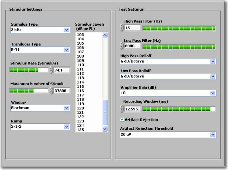
Protocol Parameters
The protocol parameters are entered using ABR Stimulus and Test Settings controls
[Hall, 1990], [Hall, 1997], [Stapells, 2002], [Stevens, 2001, (Click)], [Stevens, 2001 (Tone
Pip)]. To create a new protocol select an existing protocol and modify it.
The parameters, which can be preset in this protocol, are divided into two categories:
Stimulus Settings and Test Settings (Figure 53).
General Operating Procedures User's Manual Integrity Chapter 5
80 11049 Rev.2 Protocol Parameters
Figure 66 Protocol Stimulus and Test Settings Controls
The Stimulus Settings are used to select the stimulation parameters such as stimulus
type, stimulus level, maximum number of stimuli, stimulus rate, stimulus window,
waveform ramp setting, and the transducer type.
The Test Settings control the acquisition conditions of the waveform recording, such as
high-pass and low-pass filter settings, high-pass and low-pass filter Rolloff, the amplifier
gain, recording window duration, and the artifact rejection threshold (relevant only when
using the averaging algorithm).
Some test settings can only be modified on the Test screen. (Refer to Protocol Test
Settings on page 31 for more details).
Stimulus Settings
Stimulus Type
The following stimulus types can be selected from the drop-down menu: click or tone
bursts frequencies of 500 Hz, 1 kHz, 2 kHz, 3 kHz, and 4 kHz.
Transducer Type
Two transducer types are available from the drop-down menu: the ER-3A earphone and
the B-71 Bone Conductor.
Stimulus Rate (Stimuli/s)
The Stimulus Rate can be set for click and tone-burst stimuli. Select the number of
stimuli to produce per second from the range of 7.1 to 99.0 (in 0.1 increments). Changing
the Stimulus Rate will result in a change in the wave latency delay and in the early
wave’s amplitude. A parameter value can be set by dragging the control bar, and entering
the number in it.

Chapter 5 User's Manual Integrity General Operating Procedures
Protocol Parameters 11049 Rev.2 81
Maximum Number of Stimuli
The Maximum Number of Stimuli depends on the selected Stimulus Rate. For the
lowest Stimulus Rate of 7.1 stimuli/s the Maximum Number of Stimuli is 5964. For the
highest Stimulus Rate of 99 stimuli/s the Maximum Number of Stimuli is 83160. The
smallest value this parameter can be set to is zero (0).
The Maximum Number of Stimuli can be selected several different ways: by dragging
the control bar, entering the number in the control window, or clicking on the up arrow (to
increase the number of stimuli) or down arrow (to decrease the number of stimuli).
Window
This setting is applicable to the tone-burst stimulation type only. The window defines the
shape of the tone-burst waveform, which follows the rise, plateau, and fall portions of the
stimulus.The tone-burst signal can be Rectangular, Linear, or Blackman waveform. The
Blackman gated window is most commonly used.
Ramp
This setting is applicable to the tone-burst stimulation type only. The number of sinusoidal
waves in the raise, plateau, and fall portions of the tone burst’s waveform is controlled by
this parameter. The selections available from the drop-down menu are 2-1-2 or 2-0-2
options.
NOTE
If Click is selected as the Stimulus Type both the Window and Ramp
settings will be unavailable.
Stimulus Levels
The Stimulus Level defines either multi-level or single-level stimulation. To select a
range for multiple level tests, press and hold the Ctrl key on the keyboard and highlight
the required levels.
TIP
During the test session, while viewing the Test screen, it is possible to
change the stimulus level using the Level (dB pe SPL) sliding bar
(Figure 25). The slider indicates the value of the bottom level of the
stimuli selected. When the slider is moved, only the lower end of the
selected level range is changed.
If only one stimulus level was selected the slider will indicate that value.
If the slider is moved it changes the value of the single level.
The Stimulus Levels can be selected from a range of values.
B-71 50 to 125 dB pe FL, -10 to 65 (1 dB increment)
ER-3A 0 to 125 dB pe SPL, -30 to 95 (1 dB increment)
For the ABR protocols created for testing using the Insert earphones, levels of stimulation
could be expressed in dB nHL or in dB pe SPL depending on the selection made through
the System screen.

General Operating Procedures User's Manual Integrity Chapter 5
82 11049 Rev.2 Protocol Parameters
The levels of stimulation for testing with Insert Earphones can be selected in a range
from -30 to 95 dB nHL or from 0 to 125 in dB pe SPL.
For the ABR protocols created for testing using the B-71 Bone Conductor levels of
stimulation could be expressed in dB pe FL or dB nHL.
Levels of stimulation for testing with bone conduction can be selected in a range from -10
to 50 or 60 dB nHL or from 50 to 110 or 120 in dB FL. Bone vibrator stimulation range
depends on the Stimulus Type preset through the Protocol screen.
NOTE
Air-conducted stimuli are displayed in units of dB nHL or dB pe SPL. The
bone-conducted stimuli are displayed in units of dB nHL or dB pe FL.
These units are defined in the System screen.(Refer to Selecting the
calibration units on page 67 for more details).
Test Settings
The Test Settings control the acquisition parameters of the ABR recording, such as
high-pass filter (HZ), low-pass filter (HZ), high-pass rolloff, low-pass rolloff, amplifier gain,
recording window (ms), artifact rejection, and artifact rejection thresholds.
High-Pass filter (Hz)
The digital high-pass filter is used to filter out low frequency noise. The filter can be set to
a value in the range of 30 Hz to 300 Hz.
Low-Pass filter (Hz)
The digital low-pass filter is used to filter out high frequency noise. The filter can be set to
a value in the range of 1000 – 3000 Hz.
High-Pass Rolloff and Low-Pass Rolloff
Rolloff is defined as the rate of attenuation of a filter, expressed in dB per octave. The
High-Pass Rolloff filters the low frequencies and the Low-Pass Rolloff filters the high
frequencies. Select the High Pass Rolloff to filter either 6dB/octave or 12dB/octave and
the Low Pass Rolloff to filter either 12 dB/octave or 24 dB/octave.
Amplifier Gain (dB)
This control regulates the post Amplitrode® gain. The available values are 0 (system
default), 10, 20, and 40.
Recording Window (ms)
The Recording Window is a time period after the stimulus is presented to the patient,
during which the response is averaged and analyzed. The recording windows can be
from 0 ms up to 30 ms.
The maximum Recording Window length depends on the Stimulus Rate. From 7.1 to
33.3 Stimuli/s the maximum window is 30 ms, at 33.4 Stimuli/s the maximum window is
29.9 ms and at 99 Stimuli/s the maximum window is 10.1 ms.
Artifact Rejection
This selection box is used to switch on and off the Artifact Rejection Thresholds. When
this control box is selected the Artifact Rejection Thresholds field becomes active. If
the control box is not selected the Artifact Rejection Thresholds field is unavailable.

Chapter 5 User's Manual Integrity General Operating Procedures
Performing an ABR Test 11049 Rev.2 83
Artifact Rejection Threshold
The Artifact Rejection Threshold is used to exclude certain noise levels from the
averaging calculations. The value selected (10, 15, 20, or 25 µV) defines the lowest level
of the incoming electrophysiological activity which contains excessive electric noise. This
field is only accessible when the Artifact Rejection control box is selected.
Performing an ABR Test
To conduct a measurement, perform the following steps.
Place the VivoLink™ on the patient:
This procedure includes preparing the skin and connecting the electrodes. Begin with the
VivoLink™ Off and the Amplitrode® and electrode clips connected to the parking snaps.
Adult patient or an older child:
1. Connect the lanyard clips to the D-rings on the VivoLink™.
2. Disconnect the breakaway of the lanyard and place the longer part of the lanyard
around the patient’s neck.
3. Connect the breakaway of the lanyard to the VivoLink™. The patient may then
be placed in a chair or on a couch, whichever is more comfortable for the patient
and the operator. (Refer to Figure 7.)
Infant patient:
1. Place the VivoLink™ next to the infant on a flat surface, close enough for the
Amplitrode®, ER-3A, and B-71 Bone Conductor cables to reach the infant.
Alternatively, if the infant is held by a caregiver, the caregiver may hold the
VivoLink™ in the hands along with the infant.
CAUTION
Injury to an infant may occur.
Do not hold the VivoLink™ or any transducers over the infant’s body or
head. If any of the components are accidentally dropped, the infant may
be injured.
1. Switch On the VivoLink™. Check the status of the VivoLink™ batteries and
Bluetooth® connection.
2. Check that the Impedance Mismatch LED on the VivoLink™ is off (not luminous)
while the Amplitrode® and its clips are snapped on the designated parking snaps
on the VivoLink™.
General Operating Procedures User's Manual Integrity Chapter 5
84 11049 Rev.2 Performing an ABR Test
ATTENTION
When the contact quality mismatch LED on the VivoLink™ is On
(luminous) it indicates a poor contact between the electrodes and the
patient’s skin and may lead to incorrect measurements or misdiagnoses.
No light – means that the contact quality is good.
Amber light – means that the inverting (-) electrode does not have good
contact with the patient’s skin. Check the inverting electrode and if
necessary, re-position the electrode, replace the snap electrode pad and
prepare the skin again.
Green light – means that non-inverting (+) electrode does not have good
contact with the patient’s skin. Check the non-inverting electrode and if
necessary, re-position the electrode, replace the snap electrode pad and
prepare the skin again.
3. Prepare the patient’s skin as described in Skin preparation on page 74.
4. Place the electrode pads on the skin and connect the Amplitrode® and electrode
clips as described in Preparing the Patient on page 74.
CAUTION
Do not use electrodes if their expiration date has passed.
5. To prepare for an air-conduction test, install the ear tip into the testing ear as
directed for the
ATTENTION
To perform an ABR test with ER-3A earphones the protocol selected
must be configured to use the ER-3A Transducer Type. If it is not the
stimuli will not be transmitted through the earphones.
To perform ABR test with B-71 Bone Conductor the protocol selected
must be configured to use the B-71 Transducer Type. If it is not the
stimuli will not be transmitted through the bone conductor.
6. ER-3A Earphones on page 77.

Chapter 5 User's Manual Integrity General Operating Procedures
Performing an ABR Test 11049 Rev.2 85
ATTENTION
To ensure proper fit on the transducer and proper operation, use only ear
tips supplied by Vivosonic.
7. To prepare for a bone-conduction test, place the B-71 Bone Conductor on the
patient’s head. Refer to Application of the electrodes on page 75 for placement
details.
8. In the Test Screen, select the type of test to be performed. (Currently only ABR
is available.)
9. Select an appropriate protocol in the Applied Protocol drop-down menu.
CAUTION
Improper configuration of test protocols may result in poor quality test
results. Use clinically validated protocols for screening and assessment.
10. Press either the Right Ear or Left Ear button.
11. Press Start. The Start button will change to a Stop button.
12. Monitor the EEG Window (Figure 28) and visually estimate the amplitude of the
EEG signal.

General Operating Procedures User's Manual Integrity Chapter 5
86 11049 Rev.2 Performing an ABR Test
TIP
The noise floor in ABR tests depends on the number of sweeps and the
recorded EEG noise. For example, to achieve a 0.1 μV noise floor in an
ABR test, you will need to observe the ongoing EEG amplitude within the
following limits:
For 1,000 sweeps – within approximately ± 2-3 μV,
For 2,000 sweeps – within approximately ± 4-5 μV,
For 10,000 sweeps – within approximately ± 10 μV,
For 1,000,000 sweeps – within approximately ± 100 μV.
When excessive noise is found in an AEP test, do the following:
• Check the Contact Quality Mismatch LED status and ensure it is Off (not
luminous). If it On (luminous) and is amber, check the inverting (-) electrode
and replace the electrode or re-prepare the skin area if necessary. If it is On
and green, check the non-inverting (+) electrode and replace the electrode
or re-prepare the skin if necessary.
• Remove the Amplitrode® and its clips from the patient and snap them on the
parking snaps of the VivoLink™.
• If the noise is still excessively high, relocate the electrodes.
• When the noise is reduced, reconnect the Amplitrode® and its clips to the
patient and continue patient testing.
13. The instrument performs a test automatically. Pause the test temporarily by
pressing Pause. Press Continue or the Stop button to proceed.
14. Whether the data collection is paused or stopped, all the data collected before
pressing Pause can be saved by pressing Save. Refer to Test Control Buttons
on page 26 for more information about Start/Stop, Pause/Continue, and Save
features.
TIP
Every Start and Stop will create a new record. Save each record to have
it displayed on the Test Waveform Window graph while the next test is
taking place. If the record is not saved, it will not show on the graph
when the next test is started.
15. Press Discard/Clear Graph to clear the Test Waveform Window graph before
or after saving the results. If the graph is cleared before the results are saved,
the data will be deleted.
16. Press PRINT to print the test results.
17. Repeat the above procedure to test the other ear.
18. Remove the ear tip from the ear. Pull the ear tip from the ear canal slowly. While
removing the ear tip, slightly push it to the side to open a gap between the ear tip
and the wall of the ear canal. This will allow air to enter the ear canal occluded by
the ear tip.
Chapter 5 User's Manual Integrity General Operating Procedures
Performing an ABR Test 11049 Rev.2 87
CAUTION
Injury to the eardrum may occur.
Removing the ear tip from the ear canal too quickly may cause a
negative air pressure in the occluded ear canal and result in injury to the
eardrum.
19. Dispose of the used ear tip(s).
WARNING
Choking hazard!
To avoid accidental swallowing or inhalation of an ear tip, do not leave
the used ear tip(s) within reach of a child.
Patients should be attended during preparation or testing.
ATTENTION
If there is no AEP response for either ear, check that the ER-3A
Earphone is producing a sound. Listen to the earphone using a
reasonably audible stimulus setting such as 50 dB nHL.
20. Remove the B-71 Bone Conductor from the patient’s head.
21. Carefully remove the electrode pads form the patient’s skin to avoid pain.
CAUTION
The ear tips and electrode pads are single-use only and should be
disposed of immediately after use. To avoid transfer of disease, do not
re-use the ear tips or the electrode pads on other patients.
22. Disinfect the Amplitrode® and its clips using disinfecting wipes (included with the
Integrity™ system.

General Operating Procedures User's Manual Integrity Chapter 5
88 11049 Rev.2 Performing an ABR Test
CAUTION
To avoid transfer of disease do not reuse the Amplitrode® and its clips
without first disinfecting them.
Reviewing results
The results can be reviewed from the Database screen or a report of the results can be
printed. To review test data:
1. Select the Database tab.
2. Select the patient required.
3. Review the data in the waveform window.
4. Select Expand to view the waveforms full screen.
5. Press Report to add a description of the test.
6. Press Print and
Storing the Integrity™ system
1. Press Exit in the top right corner of the Test screen. A dialog box with the
following message will appear: “Are you sure you want to exit the instrument?”
2. Press YES to shut down the computer. The screen will turn black.
3. Close the computer lid (recommended to protect the screen and keyboard from
collecting excessive dust).
4. Turn the power switch for the computer Off.
5. Turn the optional printer Off. (Refer to the computer and printer manufacturer’s
User’s Guide for details.)
6. Unplug the computer power cord from the wall outlet.
7. Pack the VivoLink™ and accessories and place them back into their storage
cases.
Chapter 6 User's Manual Integrity Integrity™ System Care
Recharging Batteries 11049 Rev.2 89
Chapter 6 Integrity™ System Care
Recharging Batteries
VivoLink™
Refer to the recharger manufacturer’s User Manual for details on rechargeable Nickel-
Metal Hydride batteries.
Computer
When the computer is running on battery power only, it can typically provide over an hour
of testing without re-charging. Refer to the printer manufacturer’s User Manual for
instructions on how to monitor the status of the battery, and how to recharge the battery.
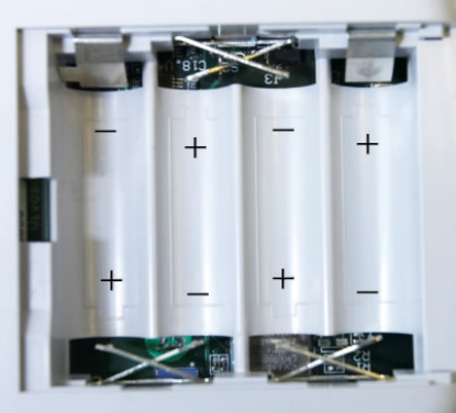
Replacing Batteries
VivoLink™
To replace the batteries:
Press lightly on the battery compartment cover and pull the cover in the direction of the
arrow on the compartment.
Remove the old batteries and dispose of them according to local regulations.
Insert four new AA batteries, Ensure that the polarity is correct by aligning the “+” signs
on the batteries with the “+” signs on the bottom of each of the four battery compartment
cells (Figure 67).
Figure 67 Battery compartment of the VivoLink™

Integrity™ System Care User's Manual Integrity Chapter 6
90 11049 Rev.2 Replacing Batteries
CAUTION
Injury to the patient or operator and damage to the VivoLink™ may
occur.
If any of the four batteries are installed backwards, the reversed polarity
may cause excessive current through this battery. The excessive current
can accelerate discharge and leakage of the battery acid, which can burn
skin and may permanently damage the device.
If the Integrity™ is not going to be used for some time, remove the
batteries from the VivoLink™ and store them in a cool, safe place. If the
batteries are left in the VivoLink™ for a prolonged period of time they
may discharge and leak the battery acid into the battery compartment,
which can burn skin and may permanently damage the device.
Computer
See the computer manufacturer’s User Manual.

Chapter 7 User's Manual Integrity Troubleshooting
Problems, Causes and Solutions 11049 Rev.2 91
Chapter 7 Troubleshooting
Problems, Causes and Solutions
ATTENTION
Do not attempt to repair the instrument; this may cause it to function
improperly.
The Integrity™ System is not a field-repairable instrument. Call your
distributor of Vivosonic Customer Support for all repairs.
Table 3 Troubleshooting Problems, Causes and Solutions
Problem Observed Possible Causes Possible Solutions
The computer does not
boot.
The battery is dead and the
computer is not plugged in.
The power outlet is not working.
The computer is not turned on.
• Charge the battery.
• Try plugging the
computer into a power
outlet that is known to
work.
• Switch the computer ON
The ON switch is located
in the center of the right
side of the computer or
check your computer’s
user manual.
The system starts and
operates, but displays
error messages.
Printer drivers (or other non-
Integrity™ system peripheral
drivers) installed on the
system by the operator may
not be compatible with the
Integrity™ system.
• Please contact Customer
support.
• Only printer drivers that
have been tested and
validated by Vivosonic to
work with the Integrity™
System may be used.
There is no signal from
the transducer (ER-3A or
B-71).
The wrong ear has been chosen.
The earphone is not inserted
properly.
• Verify that the
appropriate ear tip is
chosen.
• Verify that the foam
earphone has been
placed in the ear canal
properly.
• Verify the B-71 is affixed
properly to the patient.
The Bluetooth® wireless
connection fails.
The VivoLink™ has not been
turned on.
The VivoLink™ batteries are low
or dead.
The VivoLink™ is out of range.
The software is out of sync.
• Make sure that
VivoLink™ is switched
on.
• Check the battery voltage
(Figure 18) to make sure
that VivoLink™ batteries

Troubleshooting User's Manual Integrity Chapter 7
92 11049 Rev.2 Problems, Causes and Solutions
are charged.
• Make sure that distance
between VivoLink™ and
the computer has not
exceed 30 ft (10 m).
• Press RETRY
CONNECTION button.
• Switch the VivoLink™ off
and on.
• Restart the Integrity™.
• Refer to the Bluetooth®
Troubleshooting section
of Appendix J.
The EEG signal is above
±40 µV and is not coming
down.
The electrodes may be poorly
placed.
• Readjust the electrodes
and start again.
Cannot change the
password
The old password is being typed
incorrectly.
• Check the Num Lock is
set if using the number
pad.
• Check that the Caps Lock
is not set.
• Verify the password has
not been changed
already.
• Contact customer
support.
There is no AEP
response for either ear
while testing with the
ER-3A
The ear is not getting the
stimulus sent from the
VivoLink™
• Check that the ER-3A
earphone is producing a
sound. Listen to the
earphone using a
reasonably audible
stimulus setting such as
50 dB nHL.
• Change the ER-3A
transducers.
• If there is still no sound,
call Customer Support to
determine if the problem
is the connection on the
VivoLink™

Chapter 7 User's Manual Integrity Troubleshooting
Problems, Causes and Solutions 11049 Rev.2 93
CAUTION
Do not install printer drivers and do not use office printers that are not
tested and validated to work with the system, and supplied by Vivosonic.
This may cause improper instrument functioning, failure to print, and
error messages.

Appendix A User's Manual Integrity Technical Specifications
94 11049 Rev.2
Chapter 8 Appendices
Appendix A Technical Specifications
Intended use Hearing screening and clinical assessment in newborns, infants,
children, and adults.
Digital Signal
Processing (DSP)
method
The Kalman Weighted method, a patented method using a Linear
Minimum Mean-Square Error Filter, also called the Kalman Filter (US
Patents 6,463,411 and 6,778,955), is used to estimate ABR signals
recording and a time-averaging method. [Li 2002]
Test procedure Non-invasive.
Patient
participation/response
Not required – ABR is objective.
Diagnostic environment VivoLink™ will perform in a variety of environments (hospital,
ambulatory, or home). A sound-proof room is typically not required.
Compliant Transducers
and cables
Compliant with the requirements of EN60601-1-2:2001 Sections
36.201, 36.202
− ER-3A earphones attached to 55.5 ± 2.5 cm cable
− B-71 Bone Conductor attached to 72” cable
− OAE probe attached to 80 cm cable
Compliant Accessories Compliant with the requirements of EN60601-1-2:2001 Sections
36.201, 36.202
Amplitrode® cables length:
− between VivoLink™ and ground clip – 1 Meter
− between ground clip and “+” clip” – 25 cm
− between ground clip and “-“ clip – 40 cm
VivoLink™ - wireless interface module
Electrode type Single-use Ambu® Neuroline 720-00-S snap electrodes or equivalent.
Amplitrode® filters For ABR: 30 – 3000 Hz.
Slope: 12 dB/octave.
Frequency bands and
bandwidth of reception
The receiver operates in 79 bands separated by 1MHz, centered at
2402 MHz through 2480 MHz with a bandwidth of +/- 20 parts per
million
Frequency
characteristics of the
modulation and the
effective radiated
power of transmission
For all frequencies:
Modulation Type:
IQ Modulation
Frequency Characteristics (where centre frequency F0 = 2F1-F2):
Average delta F1 Modulation = 165 kHz (+10/-25 kHz)
Maximum delta F2 Modulation = 125 kHz
Effective Radiated Power:
+1 dBm (+/- 3dB)
ABR Numeric Latencies
Peak Accuracy of
Labeled Peaks
Peaks I, II, III, IV, and V, within an accuracy of 0.026 ms.
Amplitrode® gain For ABR: 15000,
VivoLink™ gain Selectable: 0 dB, 10 dB, 20 dB, and 40 dB.
VivoLink™ filters Selectable notch filter settings: 50 Hz, 60 Hz, and “no filter”.

Technical Specifications User's Manual Integrity Appendix A
11049 Rev.2 95
VivoLink™ resolution Analog-to-digital (A/D) conversion (in recording channels): 24 bit.
Digital-to-analog (D/A) conversion (in stimulation channels): 16 bit.
Automatic pre-testing
procedures
The measurement of the electrode contact quality.
Ear tips Type: Disposable, foam or PVC for AEP testing.
Power source The VivoLink™ is powered by four AA batteries. The system ships with
eight Nickel-Metal Hydride (NiMH) rechargeable batteries, a charger
and 4 AA Alkaline batteries.
Electrical path to the
patient
In ABR test: from the VivoLink™ through the Amplitrode® and
Electrodes. There is no electrical hazard to the patient, as the
VivoLink™ is battery-operated.
The products gained the following regulatory clearances and
approvals:
• USA: FDA clearance under 510(k) K043396.
• Canada: Health Canada Medical Device License No. 67609.
• European Union: CE Registration No. DE/CA09/0170/1207 to
1212.
• CB Test Certificate CA/023/ITS (testing to standards for
safety of electrical equipment)
Safety standards
compliance
Independent testing and audits verified that the products adheres to
the following standards:
• CB Scheme certificate (Compliance to national deviations for
67 countries)
• CSA C22.2 NO 601.1 (R2001) (Medical electrical equipment
– general requirements for safety)
• EN 980:2003 (Graphical symbols for use in the labeling of
medical devices)
• EN 55011:1998 (Limits and methods of measurement of
Radio disturbance Characteristics of Industrial, Scientific and
Medical Radio- Frequency equipment)
• EN 60601-1-1 (2001) (Collateral standard: safety
requirements for medical electrical systems (Part 1))
• EN 60601-1-2:2003 (Collateral standard. Electromagnetic
compatibility requirements and tests)
• EN 60601-2-40 (Medical electrical equipment- Particular
requirements for the safety of electromyographs and evoked
response equipment (IEC 60601-2-40:1998))
• FCC Part 15 (Title 47 CFR Part 15, Radio frequency devices)
• IEC 60601-1-4:2000 (General requirements for safety –
collateral standard for Programmable electrical medical
systems)
• ISO 13485:2003 (Medical devices - Quality management
systems)
• ISO 14971:2000 (Medical devices - Risk management for
medical devices)
• UL 60601-1:2003 UL (Standard for safety - Medical electrical
equipment)
Environmental
Conditions for
Transport and Storage
• Ambient temperature of -40C to +70C,
• Relative humidity of 10% to 100%,
• Atmospheric pressure range of 500hPa to 1060hPa.
Potential
Electromagnetic or
other interference
There are no special measures that need to be taken to protect the
instrument from interference. However the instrument may be
interfered with other equipment, even if this equipment complies with

Appendix A User's Manual Integrity Technical Specifications
96 11049 Rev.2
CISPR emissions requirements.
Minimum Computer
Requirements
• Microsoft® Windows XP® Home or Professional.
• Service Pack 1 or above
• CPU clock speed >= 1GHz
• RAM = 256 Mbytes
• Available free hard drive space after installation of operating
system = 500 Mbytes
• Display resolution = 1024 pixels x 768 pixels
• Computer mouse
• CD-ROM drive
• At least 3 USB ports.
Radio frequency related
specifications
RF Output Power rating: 4 dB mW maximum
Operating frequency range: 2.400 – 2.4835 GHz
Modulation Types: GFSK
Software Integrity™ control software.
Printers (optional) Any printer connected to the network shared by the Integrity™ System
or any computer configured to run from the Integrity System..
Items tracked in the Integrity Database User's Manual Integrity Appendix B
11049 Rev.2 97
Appendix B Items tracked in the Integrity
Database
The following items can be entered by the user and tracked by the database.
1. Patient family name
2. Patient give name
3. Hospital ID number
4. Insurance number
5. Mother's family name
6. Mother's given name
7. Gender
8. Ear (Right, Left)
9. Ethnicity
10. Address
11. State/Province
12. Zip/Postal code
13. Country
14. Telephone number
15. Date of birth
16. Time of birth
17. Age (calculated at time of test)
18. Birth Weight (Grams or Pounds:Ounces)
19. High risk registry
20. Patient comment 1
21. Patient comment 2
22. Referring Physician
23. Location of test
24. Mother’s family and give names
25. Mother’s ID number
26. Examiner
27. Date of test.
28. Time of test
29. Protocol name
30. Stimulus parameters (Types of stimuli and levels)
31. Stimulus parameters (Tone frequencies and levels)
32. Stimulus parameters (Modulated frequencies and levels)
33. Number of ABR collected response (calculated)
34. ABR stimulus polarity
35. Transducer type
36. Electrode placement
37. DPOAE levels at test frequencies
38. Noise Floor levels at test frequencies
39. TEOAE response waveform
Appendix B User's Manual Integrity Items tracked in the Integrity Database
98 11049 Rev.2
40. TEOAE levels in user-defined frequency bands
41. TEOAE noise floor in user-defined frequency bands
42. ABR response waveforms
43. Latency values of the ABR peaks
44. I peak latency (positive peak)
45. I’ peak latency (negative peak)
46. II peak latency
47. III peak latency
48. IV peak latency
49. V peak latency (positive)
50. V’ peak latency (negative)
51. I - III inter-peak latency
52. III - V inter-peak latency
53. I – I’ peak-to-peak amplitude
54. V – V’ peak to peak amplitude
55. ABR wave V Input/Output function
56. Type of test(ABR)
57. Test comment 1
58. Test comment 2

ABR Preset Protocols User's Manual Integrity Appendix C
11049 Rev.2 99
Appendix C ABR Preset Protocols
ABR air-conducted click threshold protocol
Protocol screen settings
Stimulus Type Click
Transducer Type ER-3A insert earphones
Stimulus Rate 27.7 /sec
Window Disabled
Ramp Disabled
High Pass Filter 30 Hz
Low pass Filter 1500 Hz
High Pass Rolloff 12 dB/oct
Low Pass Rolloff 12 dB/oct
Amplifier Gain 0
Recoding Window 20 ms
Artifact Rejection Disabled
Artifact Rejection Threshold Disabled
Test screen
Algorithm Kalman
Polarity Condensation
Masker Disabled
Masking Level Disabled
Noniverting Fz
Inverting A1, A2, M1, M2
Recording Side Ipsilateral
Notch Filter Disabled
Level dB nHL Defined by an Audiologist
Neurologic test protocol
Protocol screen
Stimulus Type Click
Transducer Type ER-3A insert earphones
Stimulus Rate 17.7 /sec
Window Disabled
Ramp Disabled
High Pass Filter 30 Hz
Low pass Filter 3000 Hz
High Pass Rolloff 12 dB/oct
Low Pass Rolloff 12 dB/oct
Amplifier Gain 0
Recoding Window 15 ms
Artifact Rejection Disabled

Appendix C User's Manual Integrity ABR Preset Protocols
100 11049 Rev.2
Artifact Rejection Threshold Disabled
Test screen
Algorithm Kalman
Polarity Alternating split
Masker Disabled
Masking Level Disabled
Noniverting Fz
Inverting A1, A2, M1, M2
Recording Side Ipsilateral
Notch Filter Disabled
Level dB nHL 80 dB nHL
ABR air-conducted 500 Hz tone-burst threshold
protocol
Protocol screen
Stimulus Type 500 Hz
Transducer Type ER-3A insert earphones
Stimulus Rate 27.7 /sec
Window Blackman
Ramp 2-0-2
High Pass Filter 30 Hz
Low pass Filter 1500 Hz
High Pass Rolloff 12 dB/oct
Low Pass Rolloff 12 dB/oct
Amplifier Gain 0
Recoding Window 25 ms
Artifact Rejection Disabled
Artifact Rejection Threshold Disabled
Test screen
Algorithm Kalman
Polarity Condensation
Masker Disabled
Masking Level Disabled
Noniverting Fz
Inverting A1, A2, M1, M2
Recording Side Ipsilateral
Notch Filter Disabled
Level dB nHL Defined by an Audiologist
ABR air-conducted 1000 Hz tone-burst
threshold protocol
Protocol screen

ABR Preset Protocols User's Manual Integrity Appendix C
11049 Rev.2 101
Stimulus Type 1000 Hz
Transducer Type ER-3A insert earphones
Stimulus Rate 27.7 /sec
Window Blackman
Ramp 2-0-2
High Pass Filter 30 Hz
Low pass Filter 1500 Hz
High Pass Rolloff 12 dB/oct
Low Pass Rolloff 12 dB/oct
Amplifier Gain 0
Recoding Window 25 ms
Artifact Rejection Disabled
Artifact Rejection Threshold Disabled
Test screen
Algorithm Kalman
Polarity Condensation
Masker Disabled
Masking Level Disabled
Noniverting Fz
Inverting A1, A2, M1, M2
Recording Side Ipsilateral
Notch Filter Disabled
Level dB nHL Defined by an Audiologist
ABR air-conducted 2000 Hz tone-burst
threshold protocol
Protocol screen
Stimulus Type 4000 Hz
Transducer Type ER-3A insert earphones
Stimulus Rate 27.7 /sec
Window Blackman
Ramp 2-0-2
High Pass Filter 30 Hz
Low pass Filter 1500 Hz
High Pass Rolloff 12 dB/oct
Low Pass Rolloff 12 dB/oct
Amplifier Gain 0
Recoding Window 25 ms
Artifact Rejection Disabled
Artifact Rejection Threshold Disabled
Test screen
Algorithm Kalman
Polarity Condensation

Appendix C User's Manual Integrity ABR Preset Protocols
102 11049 Rev.2
Masker Disabled
Masking Level Disabled
Noniverting Fz
Inverting A1, A2, M1, M2
Recording Side Ipsilateral
Notch Filter Disabled
Level dB nHL Defined by an Audiologist
ABR air-conducted 3000 Hz tone-burst
threshold protocol
Protocol screen
Stimulus Type 3000 Hz
Transducer Type ER-3A insert earphones
Stimulus Rate 27.7 /sec
Window Blackman
Ramp 2-0-2
High Pass Filter 30 Hz
Low pass Filter 1500 Hz
High Pass Rolloff 12 dB/oct
Low Pass Rolloff 12 dB/oct
Amplifier Gain 0
Recoding Window 25 ms
Artifact Rejection Disabled
Artifact Rejection Threshold Disabled
Test screen
Algorithm Kalman
Polarity Condensation
Masker Disabled
Masking Level Disabled
Noniverting Fz
Inverting A1, A2, M1, M2
Recording Side Ipsilateral
Notch Filter Disabled
Level dB nHL Defined by an Audiologist
ABR air-conducted 4000 Hz tone-burst
threshold protocol
Protocol screen
Stimulus Type 4000 Hz
Transducer Type ER-3A insert earphones
Stimulus Rate 27.7 /sec

ABR Preset Protocols User's Manual Integrity Appendix C
11049 Rev.2 103
Window Blackman
Ramp 2-0-2
High Pass Filter 30 Hz
Low pass Filter 1500 Hz
High Pass Rolloff 12 dB/oct
Low Pass Rolloff 12 dB/oct
Amplifier Gain 0
Recoding Window 25 ms
Artifact Rejection Disabled
Artifact Rejection Threshold Disabled
Test screen
Algorithm Kalman
Polarity Condensation
Masker Disabled
Masking Level Disabled
Noniverting Fz
Inverting A1, A2, M1, M2
Recording Side Ipsilateral
Notch Filter Disabled
Level dB nHL Defined by an Audiologist
ABR bone conducted test protocol for click
Protocol screen
Stimulus Type Click
Transducer Type B-71
Stimulus Rate 7.1 /sec
Window Disabled
Ramp Disabled
High Pass Filter 30 Hz
Low pass Filter 3000 Hz
High Pass Rolloff 12 dB/oct
Low Pass Rolloff 12 dB/oct
Amplifier Gain 0
Recoding Window 25 ms
Artifact Rejection Disabled
Artifact Rejection Threshold Disabled
Test screen
Algorithm Kalman
Polarity Alternating split
Masker Disabled
Masking Level Disabled
Noniverting Fz
Inverting A1, A2, M1, M2

Appendix C User's Manual Integrity ABR Preset Protocols
104 11049 Rev.2
Recording Side Ipsilateral
Notch Filter Disabled
Level dB nHL Defined by an Audiologist
ABR bone conducted 500 Hz tone-burst
threshold protocol
Protocol screen
Stimulus Type 500 Hz
Transducer Type B-71
Stimulus Rate 7.1 /sec
Window Blackman
Ramp 2-0-2
High Pass Filter 30 Hz
Low pass Filter 3000 Hz
High Pass Rolloff 12 dB/oct
Low Pass Rolloff 12 dB/oct
Amplifier Gain 0
Recoding Window 25 ms
Artifact Rejection Disabled
Artifact Rejection Threshold Disabled
Test screen
Algorithm Kalman
Polarity Alternating split
Masker Disabled
Masking Level Disabled
Noniverting Fz
Inverting A1, A2, M1, M2
Recording Side Ipsilateral
Notch Filter Disabled
Level dB nHL Defined by an Audiologist
ABR bone conducted 1000 Hz tone-burst
threshold protocol
Protocol screen
Stimulus Type 1000 Hz
Transducer Type B-71
Stimulus Rate 7.1 /sec
Window Blackman
Ramp 2-0-2
High Pass Filter 30 Hz

ABR Preset Protocols User's Manual Integrity Appendix C
11049 Rev.2 105
Low pass Filter 3000 Hz
High Pass Rolloff 12 dB/oct
Low Pass Rolloff 12 dB/oct
Amplifier Gain 0
Recoding Window 25 ms
Artifact Rejection Disabled
Artifact Rejection Threshold Disabled
Test screen
Algorithm Kalman
Polarity Alternating split
Masker Disabled
Masking Level Disabled
Noniverting Fz
Inverting A1, A2, M1, M2
Recording Side Ipsilateral
Notch Filter Disabled
Level dB nHL Defined by an Audiologist
ABR bone conducted 2000 Hz tone-burst
threshold protocol
Protocol screen
Stimulus Type 2000 Hz
Transducer Type B-71
Stimulus Rate 7.1 /sec
Window Blackman
Ramp 2-0-2
High Pass Filter 30 Hz
Low pass Filter 3000 Hz
High Pass Rolloff 12 dB/oct
Low Pass Rolloff 12 dB/oct
Amplifier Gain 0
Recoding Window 25 ms
Artifact Rejection Disabled
Artifact Rejection Threshold Disabled
Test screen
Algorithm Kalman
Polarity Alternating split
Masker Disabled
Masking Level Disabled
Noniverting Fz
Inverting A1, A2, M1, M2
Recording Side Ipsilateral
Notch Filter Disabled

Appendix C User's Manual Integrity ABR Preset Protocols
106 11049 Rev.2
Level dB nHL Defined by an Audiologist
ABR bone conducted 3000 Hz tone-burst
threshold protocol
Protocol screen
Stimulus Type 3000 Hz
Transducer Type B-71
Stimulus Rate 7.1 /sec
Window Blackman
Ramp 2-0-2
High Pass Filter 30 Hz
Low pass Filter 3000 Hz
High Pass Rolloff 12 dB/oct
Low Pass Rolloff 12 dB/oct
Amplifier Gain 0
Recoding Window 25 ms
Artifact Rejection Disabled
Artifact Rejection Threshold Disabled
Test screen
Algorithm Kalman
Polarity Alternating split
Masker Disabled
Masking Level Disabled
Noniverting Fz
Inverting Ai, A2
Recording Side Ipsilateral
Notch Filter Disabled
Level dB nHL Defined by an Audiologist
ABR bone conducted 4000 Hz tone-burst
threshold protocol
Protocol screen
Stimulus Type 4000 Hz
Transducer Type B-71
Stimulus Rate 7.1 /sec
Window Blackman
Ramp 2-0-2
High Pass Filter 30 Hz
Low pass Filter 3000 Hz
High Pass Rolloff 12 dB/oct
Low Pass Rolloff 12 dB/oct

ABR Preset Protocols User's Manual Integrity Appendix C
11049 Rev.2 107
Amplifier Gain 0
Recoding Window 25 ms
Artifact Rejection Disabled
Artifact Rejection Threshold Disabled
Test screen
Algorithm Kalman
Polarity Alternating split
Masker Disabled
Masking Level Disabled
Non-inverting Fz
Inverting A1, A2, M1, M2
Recording Side Ipsilateral
Notch Filter Disabled
Level dB nHL Defined by an Audiologist

Appendix D User's Manual Integrity Guidance and Manufacturer’s Declaration
108 11049 Rev.2
Appendix D Guidance and Manufacturer’s
Declaration
Emissions
All Equipment and Systems
The Integrity™ is intended for use in the electromagnetic environment specified below.
The customer or user of the Integrity™ should ensure that it is used in such an
environment.
Emission Test Compliance Electromagnetic Environment – Guidance
RF Emissions
CISPR 11
Group 1 The Integrity™ uses RF energy only for its internal
function. Therefore, its RF emissions are very low and are
not likely to cause any interference in nearby electronic
equipment.
RF Emissions
CISPR 11
Class B
Harmonics IEC
61000-3-2
Class N/A
Flicker IEC 61000-
3-3
N/A
The Integrity™ is suitable for use in all establishments,
including domestic, and those directly connected to the
public low-voltage power supply network that supplies
buildings used for used for domestic purpose.
Equipment and Systems that are NOT life-supporting
The Integrity™ is intended for use in the electromagnetic environment specified below.
The customer or user of the Integrity™ should ensure that it is used in such an
environment.
Immunity Test IEC 60601 Test
Level
Compliance
Level
Electromagnetic
Environment-
Guidance
Portable and mobile communications
equipment should be separated from
the Integrity™ by no less than the
distances calculates/listed below:
Conducted RF
IEC 61000-4-6
3 Vrms
150 kHz to 80 MHz
V1=3 Vrms D=(3.5/V1)(Sqrt P)
Radiated RF
IEC
61000-4-3
3 V/m
80 MHz to 2.5 MHz
E1=3 V/m D=(3.5/V1)(Sqrt P)
80 to 800 MHz
D=(7/E1)(Sqrt P)
800 MHz to 2.5 GHz
Where P is the max. power (watts)
and D is the recommended
separation distance (meters).
Field strength from fixed transmitters,
as determined by an electromagnetic
site survey, should be less than the
compliance levels (V1 and E1).
Interference may occur in the vicinity
of equipment containing a
transmitter.

Guidance and Manufacturer’s Declaration User's Manual Integrity Appendix D
11049 Rev.2 109
Immunity
All Equipment and Systems
The Integrity™ is intended for use in the electromagnetic environment specified below.
The customer or user of the Integrity™ should ensure that it is used in such an
environment
Immunity Test IEC 60601
Test Level
Compliance
Level
Electromagnetic Environment
Guidance
ESD
IEC 61000-4-2
±6kV Contact
±8kV Air
±6kV Contact
±8kV Air
Floors should be wood, concrete or
ceramic tile. If floors are synthetic,
the r/h should be at least 30%
EFT
IEC 61000-4-4
±2kV Mains
±1kV I/Os
N/A Battery
Operated
Device
N/A
Surge
IEC 61000-4-5
±1kV Differential
±2kV Common
N/A Battery
Operated
Device
N/A
Voltage
Dips/Dropout
IEC 61000-4-11
>95% Dip for 0.5
Cycle
60% Dip for
5 cycles
30% Dip for
25 Cycles
>95% Dip for
5 Seconds
N/A Battery
Operated
Device
N/A
Power Frequency
50/60 Hz
Magnetic Field
IEC 61000-4-8
3A/m 3A/m
Power frequency magnetic fields
should be that of a typical
commercial or hospital environment
Note: ESD compliance is dependent on a single layer of heat shrink being installed on
the insert earphone connector. If this is not installed, the connector shell should not be
touched during operation.

Appendix D User's Manual Integrity Guidance and Manufacturer’s Declaration
110 11049 Rev.2
Radio Transmissions
This equipment has been tested and found to comply with the limits for a Class B digital
device, pursuant to Part 15 of the FCC Rules. These limits are designed to provide
reasonable protection against harmful interference in a residential installation. This
equipment generates, uses, and can radiate radio frequency energy and, if not installed
and used in accordance with the instruction manual, may cause harmful interference to
radio communications. However, there is no guarantee that interference will not occur in
a particular installation. If this equipment does cause harmful interference to radio or
television reception, which can be determined by turning the equipment off and on, the
user is encouraged to try to correct the interference by one of more of the following
measures:
· Reorient or relocate the receiving antenna
· Increase the separation between the equipment and receiver
· Connect the equipment into an outlet on a circuit different from that to which
the receiver is connected.
· Consult the dealer or an experienced radio/TV technician for help.
Warning: Changes or modifications not expressly approved by Vivosonic,
Inc. could void the user’s authority to operate the equipment
This device complies with Part 15 of the FCC Rules. Operation is subject to the following
two conditions: (1) this device may not cause harmful interference and (2) this device
must accept any interference received, including interference that may cause undesired
operation.

Recommended Separation Distance User's Manual Integrity Appendix E
11049 Rev.2 111
Appendix E Recommended Separation Distance
This appendix covers the recommended separation distance between portable and
mobile radio frequency devices and the Integrity™ system.
Equipment and Systems that are NOT life-supporting.
The Integrity™ is intended for use in the electromagnetic environment in which radiate
disturbances are controlled. The customer or user of the Integrity™ can help prevent
electromagnetic interference by maintaining a minimum distance between portable and
mobile Radio Frequency Communication Equipment and the Integrity™ as recommended
below, according to the maximum output power of the communication equipment.
Max Output Power
(Watts)
Separation (m)
150kHz to 80 MHz
D= 1.1667(Sqrt P)
Separation (m)
80 to 800MNz
D=1.1667(Sqrt P)
Separation (m)
800MHz to 2.5GHz
D=2.3333(Sqrt p)
0.01 0.11667 0.11667 0.23333
0.1 0.36894 0.36894 0.73785
1 1.1667 1.1667 2.3333
10 3.6894 3.6894 7.3785
100 11.667 11.667 23.333
Appendix F User's Manual Integrity Symbols Used on the Instrument
112 11049 Rev.2
Appendix F Symbols Used on the Instrument
Label Symbol Description
Read accompanying documentation
On (power)
Off (power)
Wireless communication established
Standby
Impedance
REF: Reference or Model Number
SN: Serial Number
Date of Manufacture
Type BF equipment
0120
CE Mark with notified body number
7644
CSA 601.1
EN 60601-1
UL 2601
®
Entela certification.
Input voltage
Cell (battery)
AA Cell size
Alkaline Alkaline battery
NiMH Nickel Metal Hydride battery (NiMH)
Connector for Amplitrode®.
Connector for OAE Probe (not implemented)
Connectors for ER-3A earphones (red – the right ear,
blue – the left ear)
Symbols Used on the Instrument User's Manual Integrity Appendix F
11049 Rev.2 113
Connector for B-71 Bone Conductor
Probe Holder.
Parking Snaps for the Amplitrode® and its clips on the
VivoLink™.
Caution. Fragile. Sensitive to mechanical shock.
Made in Canada.
FCC mark
Appendix G User's Manual Integrity Overview of Clinical Applications
114 11049 Rev.2
Appendix G Overview of Clinical Applications
This is a brief overview of the clinical applications for AEP procedures. Refer to
Appendix I for references regarding this information.
General Information on ABR
What is ABR?
Auditory brainstem response (ABR) is an objective electrophysiological test of the
function and integrity of the auditory system from the inner ear to the brainstem.
ABR is an electrical response starting in the inner ear that travels
through the auditory nerve and balance nerve, to the brain stem.
What are the clinical applications of ABR?
• Hearing screening in newborns.
• Estimating hearing levels in difficult to test patients, i.e., mentally disabled,
autistic, developmentally delayed, infants and small children.
• Evaluating patients with suspected retro-cochlear pathology.
• Evaluating patients with Meniere's disease or similar disorders.
• Diagnostics of Auditory Neuropathy/Dissynchrony.
• Intra-operative monitoring of the function of the Cochlea and the 8th cranial
nerve.

ABR Latency Normative Data User's Manual Integrity Appendix H
11049 Rev.2 115
Appendix H ABR Latency Normative Data
UCLA School of Medicine Norms for Infants
Wave V Mean Latency as Function of Click
Table 4 UCLA School of Medicine norms for infants
Age in weeks 25 dB 35 dB 45 dB 55 dB 65 dB 75 dB
Mean 8.92 8.53 8.05 7.76 7.50 7.24
Newborn
SD 0.58 0.68 0.63 0.51 0.50 0.47
Mean 8.50 8.05 7.70 7.37 7.10 6.89
2 wk
SD 0.51 0.42 0.40 0.34 0.37 0.36
Mean 8.41 7.98 7.60 7.32 7.07 6.87
4 wk
SD 0.45 0.38 0.35 0.35 0.35 0.35
Mean 8.25 7.80 7.46 7.18 6.93 6.73
6 wk
SD 0.32 0.32 0.30 0.31 0.28 0.28
Mean 8.13 7.69 7.32 7.04 6.78 6.61
9 wk
SD 0.40 0.34 0.32 0.31 0.28 0.26
Mean 8.04 7.63 7.24 6.96 6.76 6.59
12 wk
SD 0.36 0.30 0.29 0.29 0.26 0.24
Mean 7.80 7.44 7.10 6.83 6.58 6.38
26 wk
SD 0.37 0.46 0.42 0.38 0.31 0.29
Mean 7.32 6.82 6.46 6.10 5.89 5.75
Adult
SD 0.40 0.30 0.25 0.23 0.23 0.23
Data collected for a click rate of 33.3 clicks/s. Infants were categorized by chronologic
age (weeks after birth).
Source: Zimmerman, M.C., Morgan, D.E., Dubno J.R. (1987). Auditory Brain Stem
Evoked Response Characteristics in Developing Infants. Annals of Otology, Rhinology,
Laryngology, 96, 291-299. Used with permission from the publisher.

Appendix H User's Manual Integrity ABR Latency Normative Data
116 11049 Rev.2
Boys Town Norms for Newborns
ABR Latency and Amplitude Values as a Function of Intensity Level in Newborns
Table 5 Boys Town norms for newborns
Wave V latency (msec)
Conception age in weeks
20 dB 40 dB 60 dB 80 dB
Mean 9.72 8.48 7.62 7.05
33 – 34
SD 0.56 0.49 0.41 0.39
Mean 9.61 8.42 7.58 7.02
35 – 36
SD 0.67 0.54 0.43 0.38
Mean 9.57 8.29 7.45 6.94
37 – 38
SD 0.74 0.51 0.44 0.42
Mean 9.36 8.11 7.30 6.82
39 – 40
SD 0.57 0.49 0.40 0.38
Mean 9.31 8.08 7.20 6.69
41 – 42
SD 0.54 0.35 0.29 0.29
Mean 9.16 7.94 7.08 6.53
43 – 44
SD 0.53 0.51 0.33 0.32
Data collected under the following measurement parameters: stimulus – click, 0.1 msec,
13/sec, monaural, Beyer DT48 earphones; acquisition – filters, 100 – 3000 Hz;
amplification, 100,000; sweeps, 1,024; analysis time, 15 msec; electrodes, Cz-Mi.
Infants were categorized by Conceptional age in weeks (gestational age at birth plus
number of weeks since birth).
Source: Gorga, M.P., Reiland, J.K., Beauchaine, K.A., Worthington, D.W, Jesteadt, W.
(1987) Auditory brainstem responses from graduates of an intensive care nursery: normal
patterns of response. Journal of Speech and Hearing Research, 30, 311-318. Used with
permission from ASHA and M. Gorga.

ABR Latency Normative Data User's Manual Integrity Appendix H
11049 Rev.2 117
Boys Town Norms for Infants
ABR Latency Values as a Function of Intensity Level in Children Ages 3 Months to 3
Years
Table 6 Boys Town norms for infants
Latency (msec)
Wave V Wave I
Age in
months 20 dB 40 dB 60 dB 80 dB
Mean 8.72 7.43 6.73 6.25 1.59
3 – 6
SD 0.53 0.36 0.33 0.32 0.17
Mean 8.59 7.28 6.56 6.10 1.59
6 – 9
SD 0.61 0.38 0.29 0.26 0.16
Mean 8.31 7.05 6.31 5.90 1.59
9 -12
SD 0.54 0.37 0.29 0.27 0.18
Mean 8.28 7.10 6.30 5.91 1.59
12 – 15
SD 0.60 0.45 0.33 0.27 0.17
Mean 8.33 7.00 6.24 5.84 1.58
15 – 18
SD 0.61 0.38 0.24 0.27 0.14
Mean 8.22 6.95 6.19 5.74 1.55
18 – 21
SD 0.62 0.36 0.18 0.19 0.12
Mean 8.05 6.79 6.14 5.71 1.57
21 – 24
SD 0.58 0.33 0.29 0.26 0.17
Mean 8.30 6.89 6.09 5.71 1.53
24 – 27
SD 0.46 0.29 0.22 0.19 0.14
Mean 7.98 6.75 6.08 5.60 1.59
27 – 30
SD 0.42 0.33 0.28 0.22 0.19
Mean 8.12 6.79 6.07 5.68 1.56
30 – 33
SD 0.53 0.32 0.31 0.27 0.16
Mean 8.10 6.82 6.06 5.68 1.56
33 – 36
SD 0.68 0.38 0.31 0.27 0.15
Data collected under the following measurement parameters: stimulus – click, 0.1 msec,
13/sec, monaural, Beyer DT48 earphones, 0 dB = 30 dB peSPL; acquisition – filters, 100
– 3000 Hz; amplification, 100,000; sweeps, 1,024; analysis time, 15 msec; electrodes,
Cz-Mi.
Gorga, M.P., Kaminski, J.R., Beauchaine, K.L., Jesteadt, W., Neely, S.T. (1989). Auditory
brainstem responses from children three months to three years of age: normal patterns of
response. Journal of Speech and Hearing Research, 32, 281-288. Used with permission
from ASHA and M. Gorga.

Appendix H User's Manual Integrity ABR Latency Normative Data
118 11049 Rev.2
Absolute and Interwave Latency Values
These latency values for the primary components of the ABR
Table 7 Absolute and interwave latency values
Stimulus
Intensity
dB nHL
I II III IV V
I – III III – V I - V
Mean 1.53 2.53 3.58 4.56 5.37 2.05 1.79 3.84
90
SD 0.11 0.09 0.09 0.17 0.12 0.14 0.14 0.16
Mean 1.62 2.68 3.68 4.68 5.47 2.06 1.79 3.85
80
SD 0.12 0.11 0.08 0.22 0.12 0.11 0.09 0.14
Mean 1.82 2.79 3.85 4.92 5.64 2.03 1.79 3.82
70
SD 0.17 0.12 0.13 0.24 0.16 0.11 0.12 0.11
Mean 2.04 2.98 4.06 5.11 5.88 2.02 1.72 3.75
60
SD 0.20 0.15 0.21 0.31 0.25 0.12 0.10 0.11
Mean 2.43 3.69 4.60 5.43 6.19 2.02 1.56 3.64
50
SD 0.17 0.10 0.23 0.25 0.32 0.19 0.18 0.19
Mean 3.01 4.05 4.94 5.65 6.65 1.85 1.71 3.60
40
SD 0.25 0.18 0.25 0.49 0.32 1.85 1.71 3.60
Mean - - 5.45 - 7.24 - 1.74 -
30
SD - - 0.30 - 0.42 - 0.26 -
Mean - - 5.56 - 7.52 - 1.88 -
20
SD - - 0.57 - 0.63 - 0.23 -
Source: Linda J. Hood. Clinical Applications of the Auditory Brainstem Response.
Singular Publishing Group, Inc. 1998, San Diego, 285 pages. Used with permission from
publisher.

References User's Manual Integrity Appendix I
11049 Rev.2 119
Appendix I References
This appendix contains references for The ABR latency and amplitude values, terms,
abbreviations, the definitions for the Glossary of Terms, and a summary of clinical
applications of ABR found in Appendix G.
Gorga, M.P., Reiland, J.K., Beauchaine, K.A., Worthington, D.W, Jesteadt, W. (1987)
Auditory brainstem responses from graduates of an intensive care nursery: normal
patterns of response. Journal of Speech and Hearing Research, 30, 311-318.
Gorga, M.P., Kaminski, J.R., Beauchaine, K.L., Jesteadt, W.,, Neely, S.T. (1989) Auditory
brainstem responses from children three months to three years of age: normal
patterns of response. Journal of Speech and Hearing Research, 32, 281-288.
Hall, J.W., III. Handbook of Auditory Evoked Responses. Allyn and Bacon, 1990, ISBN:
0-205-13566-8.
Hall, J., Mueller, G. Audiologists’ Desk Reference: Diagnostic Audiology Principles and
Procedures. Singular: San Diego, 1997. ISBN: 1-56593-269-2
Hood, L. Clinical Applications of the Auditory Brainstem Response. Singular: San Diego,
1998. ISBN: 1-56593-200-5.
Li, X., Sokolov, Y., Kunov, H. System and method for processing low signal-to-noise ratio
signals. US Patent 6,463,411. Oct. 8, 2002.
Stevens, Ed. J., Neonatal Hearing Screening and Assessment. Click Auditory Brainstem
Response Testing in Babies. A recommended test protocol. 26 November 2001.
Source: www.unhs.org.uk
Stevens, Ed. J., Neonatal Hearing Screening and Assessment. Auditory Brainstem
Response Testing in Babies Using Tone Pip Stimulation. A recommended test
protocol. 26 November 2001.. Source: www.unhs.org.uk
ASHA, Short Latency Auditory Evoked Potentials. Audiologic Evaluation Working Group
on Auditory Evoked Potentials. 1987.
Stach, B.A. Comprehensive Dictionary of Audiology. Williams & Wilkins: Baltimore, 1997.
ISBN: 0-683-18075-4.
Stapells, D. Frequency-Specific Evoked Potential Audiometry in Infants. In: R. Seewald,
ed. A Sound Foundation Through Early Amplification 2001. Proceedings of the
Second International Conference. Basel, Switzerland, Phonak AG, 2002, pp. 13-31.
Zimmerman, M.C., Morgan, D.E., Dubno J.R. (1987). Auditory Brain Stem Evoked
Response Characteristics in Developing Infants. Annals of Otology, Rhinology,
Laryngology, 96, 291-299.
Merriam-Webster Medical Dictionary, (2005). Source: http://www2.merriam-
webster.com/cgi-bin/mwmednlm?book=Medical
Appendix I User's Manual Integrity References
120 11049 Rev.2
Glossary of Terms
The following definitions are used in this manual and can also be found in the Integrity ™
software instrument screens.
The terms shown here where defined using the information referenced in Appendix I.
Acoustic coupler Cavity of predetermined shape, volume, and acoustic impedance such as
Occluded Ear Simulator (Zwislocki Coupler) that couples the Probe and a
measuring microphone of the sound level meter and is used for calibration of
stimuli.
Air conduction A mode of presenting auditory stimuli via earphones placed over the ear or
within the ear canal.
Algorithm The algorithm field allows selection of the signal processing algorithm used to
combine successive ABR responses. The Integrity(tm) system offers the
standard Averaging method and the Kalman Weighted averaging
method.
Alternating
Stimulus Polarity
Alternating presentation of rarefaction and condensation polarity stimuli.
Amplitrode® An integrated pre-amplifier and electrode into a combined unit for attaching or
affixing to a subject.
Artifact Unwanted signal that may interfere with the measurement of desired signals.
Artifact Rejection
Threshold (ART)
The sound pressure level in µV above which the detected acoustic signal is
considered an artifact..
Auditory
Brainstem
Response (ABR)
Auditory evoked potential originating from the cranial nerve VIII and auditory
brainstem structures.
Averaging ABR processing algorithm, which uses a standard time averaging technique
when equivalent weighting is given to each ABR collected response. Weights
assigned to each collected ABR response are based on the noise in that
response. Sweeps contaminated with artifacts above a certain artifact-rejection
threshold (ART) are excluded from the averaging.
Bone vibrator A transducer that is used to present sounds to the skull that reached the Cochlea
through the head tissues and bones, i.e. bypassing the middle ear.
Channel A single set of inputs into an Auditory Evoked Potential system (e.g., from one
pair of electrodes) or a single output from a stimulus generator (e.g., to the right
earphone).
Click Short-duration, broadband sound produced by applying a short electric pulse to
the receiver of the probe, typically around 100 μsec.
Click Bandwidth The frequency range of the click spectrum within 6 dB from its maximum.
Click Duration
(CD)
Duration of an electric pulse driving the receiver to elicit a click, in microseconds
(μs).
Component A peak or wave in the response waveform.
Common Mode
Rejection (CMR)
A noise reduction technique implemented by the differential amplifier where an
identical (common) noise at two electrodes is subtracted from the
electrophysiologic response.
Condensation
(Positive)
Stimulus Polarity
The initial displacement of the stimulus, produced with a positive-voltage
electrical signal and an outward movement of the acoustic transducer.
Customizable Settings that can be changed by the User.
Database An organized collection of data.
dB HL A decibel scale referenced to acceptable standards for normal hearing (0 dB is
averaged normal hearing for each audiometric test frequency).
References User's Manual Integrity Appendix I
11049 Rev.2 121
dB nHL A decibel scale used in auditory brainstem response measurement referenced to
average behavioral thresholds for click or tone burst stimuli collected on a small
group of normal hearing patients.
dB SPL The logarithmic ratio of the RMS sound pressure of an acoustic signal, Prms to
the reference sound pressure, P0 = 20 μPa = 2 * 10-5 Pa, calculated as: SPL
(dB) = 20 * log (Prms/P0).
dB peSPL The decibel level of a 1000 Hz tone at an amplitude equivalent to the
peak of a transient signal such as a click.
Eartip A part of the ER-3A earphone, typically made of soft plastic, that is inserted onto
the ear canal and used to test for acoustic isolation of the ear canal from the
environment.
Earphone A device for presenting a sound stimulus to the ear, consisting of an acoustic
transducer for converting an electrical signal into sound and a cushion that
couples the transducer to the ear.
Electroence-
phalograph
(EEG)
An instrument used to study and record brain activity.
Envelope
(Window)
The shape of the overall waveform of an acoustic stimulus that follows the rise,
plateau, and fall portions of the stimulus.
Epoch A time period, such as the analysis time in evoked response measurement.
Fall time The time from the maximum amplitude of the stimulus, or the end of the plateau,
to some measure of baseline (zero voltage).
Filter An electronic device for eliminating electrical energy in a specific frequency
region while allowing other frequencies to pass.
Gain Increase in amplitude or energy of an electrical signal amplification. Gain is the
difference between the input signal and the output signal.
Ground A connection from a piece of electronic equipment, or a person, to the actual
ground or a relatively large metal structure that will provide an electrical ground.
The ground electrode from a person is connected to the grounding circuit on an
evoked response system. A good ground connection reduces electrical
interference in evoked response recording.
GUI Graphic User Interface
High Pass Filter A filter that passes electrical energy above a specific cutoff frequency to
eliminate (filters out) energy below that frequency.
In situ In the natural position or place on the patient.
In situ pre-
amplification
Pre-amplifies the AEP signal at its scalp with the Amplitrode®, which is
positioned on the ground electrode.
Inter-peak
Latency
The difference in milliseconds between two peaks of ABR waveform, such as the
difference between the latencies of ABR Wave I and III.
Inverting
electrode
An electrode that is attached to the negative voltage input (inverts the
input by 180º) of a differential amplifier. This electrode is typically placed
on the earlobe, mastoid, or nape of the neck in ABR recording.
Kalman
Weighted
This signal processing algorithm combines successive ABR responses through
the assignment of weights to each response. A higher weight is assigned to
"better" responses (i.e. those with less noise contamination). The weights are
optimally selected through the use of the Kalman filter, which acts as a linear
minimum mean-square error filter. As such, Kalman Weighted signal
processing (a) gives less weight to the noise-contaminated responses and (b)
emphasizes less noisy responses. In addition, this method processes signals in
real time without rejecting any time segments (even those containing significant
artifacts).
Latency A time interval between two events (e.g. the stimulus and response).
Low pass filter A filter that passes electrical energy below a specific cutoff frequency and
Appendix I User's Manual Integrity References
122 11049 Rev.2
eliminates (filters out) energy above the frequency.
Masking
(Masker)
The constant level of the background noise presented to the non-tested ear in an
audiometric procedure or ABR measurement.
Mastoid A portion of the temporal bone located behind the external ear.
Microvolt (μV) One millionth of a Volt.
Microsecond (μs) One millionth of a second.
Millisecond (ms) One thousandth of a second.
nHL Normalized hearing level. The decibel level of sound that lacks a standardized
reference, as opposed to standardized pure-tone audiometry levels. It is
referred to behaviorally determined normative levels, obtained from a group of
normally hearing listeners and expressed in dB nHL.
Non-inverting
electrode
The electrode that is attached to the positive voltage (non-inverting) input of a
differential amplifier. This electrode is typically placed on the high forehead in
ABR recording.
Notch filter A type of filter used in Evoked Response measurement, designated to reduce
interference from power line noise – 50 Hz or 60 Hz depending on the region of
the world. Notch filter may introduce filter distortion in AEP, and is recommended
to be switched off in most tests unless a strong electrical interference is present.
Occluded Ear
Simulator
Occluded ear simulator for the measurement of earphones coupled to the ear
with ear inserts, as per IEC 711-1981, ANSI S3.25-1979 (R 1986), for example
Brüel & Kjær Ear Simulator Type 4157.
Peak A component of an evoked response waveform, or the extreme amplitude for
the component; often used to describe-voltage components.
Peak equivalent
force level (peFL)
The numeric value of the sound pressure vibratory force level of a long
duration sinusoidal signal which, when fed to the same transducer under
the same test conditions has the same peak-to-peak sound pressure of
a vibratory force amplitude as the transient signal (click).
Peak equivalent
sound pressure
level (peSPL)
The decibel level of a 1000 Hz tone at an amplitude equivalent to the peak of a
transient signal such as a click.
Polarity The voltage characteristic of the stimulus or waveform response. Response
polarity depends on the location of the electrode plugged into the positive input
versus the electrode plugged into the negative voltage input of the differential
physiological amplifier relative to the neural generator.
Preamplifier An electronic device that receives an electric signal, such as an evoked
potential, directly from the electrodes, and increases the amplitude of the signal
before it is sent on for further processing such as amplification, filtering, and
averaging.
Protocol A set of parameters, typically user-defined, that instructs the system how to
automatically perform a test. It covers stimulus settings, DSP settings, etc.
Rarefaction
(negative)
Stimulus Polarity
The initial displacement of the stimulus, produced with a negative-voltage
electrical signal and inward movement of the acoustic transducer
Rate The number of stimulus repetitions per unit of time, usually 1 second.
Repetitions
(Sweeps)
The number of single reoccurring events, such as a waveform, that are
presented in a set period of time.
Sound level Sound pressure level indicated by a sound level meter, with dynamic response
and weighting characteristics conforming to the requirements of IEC 651 or ANSI
S.1.4. When not otherwise qualified, the term denotes a weighted sound level.
Stimulus Sound energy presented to the patients through the transducer.
Stimulus rate Number of stimuli presented per second.
Stimulus level The sound level of an acoustic stimuli as measured in an acoustic coupler,
usually an Occluded Ear Simulator (Zwislocki Coupler). In DPOAE tests, the
References User's Manual Integrity Appendix I
11049 Rev.2 123
levels of primaries, are typically presented in the L1/L2format, for example 65/55
dB SPL.
Test A complete sequence of stimuli presentation and response recording performed
according to a protocol within one test session.
Test Type The type of tests measurements performed by a device
Tone burst A brief pure tone stimulus having a rapid rise and fall time with a duration
sufficient enough to be perceived as having tonality (usually less then 1 sec).
Transducer An electroacoustic devise for converting one form of energy into another.
VivoLink™ The world’s first wireless interface module used in auditory electrophysiology. It
is a universal platform: It can perform ABR, ASSR, DPOAE, and TEOAE tests,
and has the potential to add other testing modalities on the same platform. (Note
- not all modalities are released yet, only ABR is currently available) It is
operated by a microprocessor, controlled from a remote computer through
Bluetooth®, and powered by batteries.
Wave The rise and fall of a voltage. A wave component is usually attributed to neural
activity (action potential or dendritic activity) of a generator or several generators
of a response.
Wave
reproducibility
The degree to which a recorded waveform can be reproduced in another similar
recording event.
Waveform A form or shape of a wave, represented graphically as magnitude in a function of
time.

Appendix J User's Manual Integrity Bluetooth® Troubleshooting
124 11049 Rev.2
Appendix J Bluetooth® Troubleshooting
Introduction
This document has been written to describe the process of troubleshooting the Bluetooth
installation. Please read the instructions in their entirety and following the suggestions
before calling for technical support.
I connect my dongle to my computer and nothing happens
If no activity takes place after inserting the Bluetooth dongle to the computer it is
because the Bluetooth driver has not been installed.
Please follow the Bluetooth driver installation instructions from page - 3 - to page
- 18 - of the Installation Instructions to install the drivers and configure the
services and security for Bluetooth.
I insert the dongle to the back of the computer and the Bluetooth icon in the
system tray remains off.
If your Bluetooth icon ( ), which is found in the system tray, in the lower right corner of
the screen is turned off it could be for the following reasons:
1. The Bluetooth Driver is not properly installed
Action - Re-install the Bluetooth driver and ensure that the settings have been
configured correctly.
2. the Bluetooth dongle is not plugged in into the proper USB connection.
Ensure that the Bluetooth driver is installed and that the dongle is connected to
the same port as it was during the driver installation.
3. The Bluetooth dongle may not be connected properly.
To ensure that the dongle is properly connected check that the LED on the
dongle is lit. If the LED is NOT lit, remove the dongle and then connect it again.
I have installed the Bluetooth driver and made the proper connection to the
VivoLink but the connection is not recognized after a system shutdown.
This problem is usually caused by incorrectly configured Windows® Bluetooth settings. If
the Bluetooth driver does not recognize the previous settings do the following:
1. Please follow the installation instructions for the Bluetooth Drivers and Services
from page - 3 - to page - 12 -of the Installation Instructions found at the back of
this User’s Manual binder.
Index User's Manual Integrity
11049 Rev.2 125
Index
% Rejected .................................... 38
AB data ......................................... 38
display....................................... 43
ABR ................................................ 1
ABR test........................................ 84
Access
data............................................ 54
Activate
protocol ..................................... 64
software..................................... 68
AEP................................................. 2
Algorithms..................................... 4
Alternating .................................... 34
Alternating split ............................ 34
Amplifier Gain.............................. 83
Amplitrode®................................. 19
damage prevention.................... 20
electrodes .................................. 35
Applications................................ 114
Apply
electrode.................................... 76
Archive
data............................................ 60
Artifact Rejection.......................... 83
Artifact Rejection Threshold......... 84
Audible levels
discomfort ................................... 8
Averaging...................................... 34
B-71
stimulation level........................ 37
B-71 Bone Conductor ................... 79
Backup
records....................................... 70
Batteries
recharging ................................. 90
replacing.................................... 90
Battery
compartment ....................... 18, 32
indicator .............................. 12, 32
birth weight
units........................................... 68
Blockage ......................................... 7
Bluetooth............................ 3, 11, 15
LED..................................... 26, 32
troubleshoot............................. 124
Calibration....................................... 8
units........................................... 68
Clear
window.....................................See
Click ............................................. 38
ABR ............................................ 1
Clinic information......................... 72
Clinical Applications .................. 114
Clinical benefits ............................ 20
Components................................... 9
Condensation................................. 34
Configuration.................................. 9
Configure
system ....................................... 67
Connection
failed ......................................... 33
Connectors
accessory................................... 16
Contact quality
correcting problem.................... 77
poor ........................................... 40
Test screen ................................ 77
VivoLink LED .......................... 76
Contact Quality............................. 30
LED........................................... 85
Contact Quality mismatcch........... 40
contraindication............................... 7
Contralateral ............................... 36
Correlation Coefficient ................. 38
Create
protocol ..................................... 64
Current Day/Time
Display...................................... 31
Index User's Manual Integrity
126 11049 Rev.2
Data
AB buffered .............................. 38
archive....................................... 60
backing up................................. 70
customize .................................. 56
Discard...................................... 29
export ........................................ 59
lost............................................. 30
merge......................................... 71
Pause ......................................... 28
report......................................... 57
results........................................ 56
save ..................................... 29, 71
select results.............................. 55
view..................................... 26, 53
waveforms................................. 41
Database.......................................... 5
access ........................................ 54
tracked items............................. 98
waveform window .................... 56
Database screen....................... 26, 53
define password ...... 53, 54, 63, 69
expanded view .......................... 60
latency vs intesity graph............ 61
patient list.................................. 54
query ......................................... 56
Date
display....................................... 31
incorrect .................................... 32
Date of Birth ................................. 48
Deactivate
protocol ..................................... 64
Define
battery information.................... 68
birth weight units ...................... 68
password ................. 53, 54, 63, 69
transducer.................................. 68
Delete
protocol ..................................... 66
records....................................... 60
test from planner................. 26, 52
waveform .................................. 44
Diagnositc
audiometry .................................. 1
Discard
data...................................... 29, 46
Display
AB............................................. 43
dongle.......................................... 124
Driver
Bluetooth................................. 124
DSP ............................................... 95
Ear
discharge ..................................... 7
right and left button................... 30
Ear tips................................... 10, 34
Earlobe placement......................... 75
EEG Window................................ 41
Electrode
application................................. 76
brand ......................................... 36
contact quality mismatch .......... 40
inverting (-)............................... 35
non-inverting (+)....................... 35
placement............................ 35, 73
Electromagnetic Compatibility....... 6
EMC................................................ 6
Emissions.................................... 109
Environment.................................... 5
ER-3A
stimulation level........................ 37
ER-3A Earphones ......................... 78
ERA.............................................. 20
Error
measurment................................. 8
Examiner....................................... 52
Expanded view.............................. 60
Export............................................ 59
Filter
high and low pass...................... 83
notch.................................... 36, 41
Rolloff....................................... 83
Filters ............................................ 20
Graph
Latency vs Intensity............ 38, 61
Y-axis scale............................... 44
Ground placement......................... 75
High-Pass filter ............................. 83
Horizontal.................................... 36
Immunity..................................... 110
Index User's Manual Integrity
11049 Rev.2 127
Impedance
indicator .................................... 14
Indications....................................... 6
Inflammation................................... 7
Installation
separation distance.................. 111
Integrity
Intended use ................................ 1
Integrity system
features........................................ 4
setup.......................................... 21
unpackaging.............................. 21
Integrity™ system
General Configuration ................ 9
Interference
notch filter................................. 36
Ipsilateral..................................... 35
Kalman filter................................. 33
Label
peaks ................................... 43, 44
Lanyard ......................................... 16
Latency
labels ................................... 43, 44
normative data......................... 115
norms......................................... 44
peak-to-peak data...................... 45
Latency intensity........................... 38
Latency norms............................... 44
international standards .............. 44
LED indicator................................ 11
Level ............................................. 36
List
patient........................................ 51
protocol ..................................... 64
Low-Pass filter.............................. 83
Masker........................................... 34
Masking level................................ 34
Mastoid placement........................ 75
Medial........................................... 36
Merge
records....................................... 71
Nape placement............................. 75
NeuroLine ..................................... 11
Noise
artifacts...................................... 20
Contact Quality......................... 30
masker....................................... 34
masking level............................ 34
Source of..................................... 2
Noise floor .................................... 87
Notch Filter................................... 36
Num of Stim.................................. 38
Number of Stimuli ........................ 38
Operation
general procedures .................... 73
Operator .......................................... 5
Password
define....................... 53, 54, 63, 69
Patient
date/time of birth....................... 48
enter information................. 47, 48
infant ......................................... 12
preparation ................................ 75
print........................................... 31
selecting .............................. 26, 49
status ......................................... 34
Patient screen
layout......................................... 63
Patients
contraindications......................... 7
indications for ............................. 6
selectable................................... 27
sorting ....................................... 48
Patients screen......................... 26, 47
customizing look....................... 48
Pause and Resume......................... 28
Planner
enter information....................... 51
selecting tests ............................ 52
Planner screen............................... 50
Polarity.......................................... 34
Poor contact quality.................... 40
Power ............................................ 13
low battery .......................... 12, 32
Print
waveform .................................. 30
Printer
setup.......................................... 69
Index User's Manual Integrity
128 11049 Rev.2
Protocol
applied....................................... 28
define......................................... 65
parameters................................. 80
preset....................................... 100
settings ...................................... 80
Protocol screen...... 26, 33, 37, 63, 81
define password ...... 53, 54, 63, 69
Query
database entries......................... 56
protocol ..................................... 65
Range ............................................ 12
Rarefaction.................................... 34
Recording Window....................... 83
Records
archive....................................... 60
delete......................................... 60
References................................... 119
Report............................................ 57
Restore
database..................................... 70
Review
data............................................ 53
Save
data............................................ 29
records....................................... 71
Screens
General...................................... 26
Test screen ................................ 26
Select
data............................................ 55
printer........................................ 69
Separation Distance .................... 111
Shipping.......................................... 8
Signal Information ........................ 37
Skin damage.................................... 7
Sort
database information................. 55
Start/stop....................................... 28
Stimulation
polarity...................................... 34
Stimulation level........................... 36
Stimulus Settings................... 80, 81
Stimulus Type............................... 38
Storing........................................... 89
Symbols....................................... 112
System
care............................................ 90
preparation ................................ 80
storage....................................... 89
System screen.................... 26, 37, 67
Test
plan...................................... 27, 50
type............................................ 28
Test conditions.............................. 51
Test Parameters
define............................. 26, 37, 63
Test screen
% rejected.................................. 38
algorithm................................... 33
averaging................................... 34
clear........................................... 29
contact quality..................... 30, 40
correlation coefficient............... 38
current day/time ........................ 31
Discard...................................... 29
ear tips....................................... 34
EEG........................................... 41
Kalman filter............................. 34
latency intensity ........................ 38
leave.......................................... 46
level........................................... 36
masker....................................... 34
masking level............................ 34
number of stimuli...................... 38
Patients...................................... 27
pause ......................................... 28
polarity...................................... 34
print........................................... 30
recording side............................ 35
Resume...................................... 28
right ear and left ear................. 30
Save........................................... 29
Start/stop................................... 28
status ......................................... 34
Stimulus type ............................ 38
test plans.................................... 27
Test type.................................... 28
Y-axis scale............................... 44
Test Settings........................... 80, 83
Tone-burst..................................... 38
Index User's Manual Integrity
11049 Rev.2 129
Transducer
define......................................... 68
selection .................................... 77
Transducer Type ........................... 38
Troubleshooting............................ 92
Bluetooth................................. 124
Unit ID .......................................... 69
Units
birth weight............................... 68
calibration ................................. 68
Values
latency....................................... 38
View
data...................................... 26, 53
VivoLink
Contact Quality......................... 85
VivoLink™ .................................. 11
connector panel......................... 14
front panel................................. 13
placement.................................. 12
Waveform
Clear.......................................... 29
data............................................ 45
delete......................................... 44
expanded view .......................... 60
functions of ............................... 56
handles ...................................... 42
label..................................... 43, 44
markup ...................................... 45
Pause ......................................... 28
window...................................... 41
Y-axis scale............................... 44
Waves I and V............................... 44
Wireless connection...................... 33
Y-axis scale................................... 44

INSTALLATION INSTRUCTIONS
Installation Instructions, Document 11049 Revision 2 as addendum to User’s Manual
Installation Instructions
11049 Rev.2
- 2 -
Table of Figures
INSTALLATION SCREEN CAPTURE 1 BLUETOOTH INTRODUCTION ........................................................... - 3 -
INSTALLATION SCREEN CAPTURE 2 BLUETOOTH INSTALLATION WELCOME.............................................. - 4 -
INSTALLATION SCREEN CAPTURE 3 DESTINATION................................................................................ - 4 -
INSTALLATION SCREEN CAPTURE 4 DESTINATION FOLDER ................................................................... - 5 -
INSTALLATION SCREEN CAPTURE 5 INSTALLING WIDCOMM ............................................................... - 5 -
INSTALLATION SCREEN CAPTURE 6 DRIVER SIGNATURE NOTICE .......................................................... - 6 -
INSTALLATION SCREEN CAPTURE 7 WARNING - WINDOWS LOGO TESTING............................................. - 6 -
CONFIGURATION SCREEN CAPTURE 1 START | RUN MENU ................................................................... - 7 -
CONFIGURATION SCREEN CAPTURE 2 RUN WINDOWS® INF DIRECTORY .............................................. - 7 -
CONFIGURATION SCREEN CAPTURE 3 WINDOWS® INF DIRECTORY ...................................................... - 8 -
CONFIGURATION SCREEN CAPTURE 4 RUN DEVICE MANAGER ............................................................. - 8 -
CONFIGURATION SCREEN CAPTURE 5 DEVICE MANGER ...................................................................... - 9 -
CONFIGURATION SCREEN CAPTURE 6 OPTIONS WINDOW ..................................................................... - 9 -
CONFIGURATION SCREEN CAPTURE 7 NEW HARDWARE WINDOW....................................................... - 10 -
CONFIGURATION SCREEN CAPTURE 8 INSTALL FROM SPECIFIC LOCATION............................................ - 11 -
CONFIGURATION SCREEN CAPTURE 9 DEVICE LIST ........................................................................... - 12 -
CONFIGURATION SCREEN CAPTURE 10 CONTROL PANEL - CATEGORY VIEW ....................................... - 13 -
CONFIGURATION SCREEN CAPTURE 11 CONTROL PANEL - CLASSIC VIEW........................................... - 13 -
CONFIGURATION SCREEN CAPTURE 12 INITIAL BLUETOOTH CONFIGURATION WIZARD .......................... - 14 -
CONFIGURATION SCREEN CAPTURE 13 BLUETOOTH GENERAL INFORMATION ....................................... - 14 -
CONFIGURATION SCREEN CAPTURE 14 SERVICES AVAILABLE............................................................. - 15 -
CONFIGURATION SCREEN CAPTURE 15 CONFIGURE SERVICES........................................................... - 15 -
CONFIGURATION SCREEN CAPTURE 16 CONGRATULATIONS............................................................... - 16 -
CONFIGURATION SCREEN CAPTURE 17 CONFIGURATION - LOCAL SERVICES ........................................ - 16 -
CONFIGURATION SCREEN CAPTURE 18 LOCAL SERVICES PROPERTIES DIALOG .................................... - 17 -
CONFIGURATION SCREEN CAPTURE 19 CONFIGURATION - CLIENT SERVICES........................................ - 17 -
CONFIGURATION SCREEN CAPTURE 20 CLIENT SERVICES PROPERTIES DIALOG.................................... - 18 -
CONFIGURATION SCREEN CAPTURE 21 FILES ON INTEGRITY CD ........................................................ - 18 -
CONFIGURATION SCREEN CAPTURE 22 CONFIRM REQUIRED SOFTWARE ............................................. - 19 -
CONFIGURATION SCREEN CAPTURE 23 BLUETOOTH CONFIGURATION FILES......................................... - 19 -
CONFIGURATION SCREEN CAPTURE 24 MSDE INSTALL START........................................................... - 20 -
CONFIGURATION SCREEN CAPTURE 25 MSDE INITIALIZATION ........................................................... - 20 -
CONFIGURATION SCREEN CAPTURE 26 INTEGRITY INITIALIZATION....................................................... - 21 -
CONFIGURATION SCREEN CAPTURE 27 VIVOSONIC WELCOME............................................................ - 21 -
CONFIGURATION SCREEN CAPTURE 28 CLOSE SQL SERVER ............................................................ - 22 -
CONFIGURATION SCREEN CAPTURE 29 MSDE INSTALLATION ............................................................ - 22 -
CONFIGURATION SCREEN CAPTURE 30 VIVOSONIC INSTALLSHIELD WIZARD COMPLETE ........................ - 22 -
CONFIGURATION SCREEN CAPTURE 31 BLUETOOTH ICON.................................................................. - 23 -
CONFIGURATION SCREEN CAPTURE 32 BLUETOOTH PLACES.............................................................. - 23 -
CONFIGURATION SCREEN CAPTURE 33 BLUETOOTH OPTIONS ............................................................ - 23 -
CONFIGURATION SCREEN CAPTURE 34 VIVOLINK DEVICE FOUND ....................................................... - 24 -
CONFIGURATION SCREEN CAPTURE 35 VIVOLINK DIRECTORY ............................................................ - 24 -
CONFIGURATION SCREEN CAPTURE 36 CONNECTING WINDOW AND TASKBAR ...................................... - 25 -
CONFIGURATION SCREEN CAPTURE 37 PIN CODE REQUEST .............................................................. - 25 -
CONFIGURATION SCREEN CAPTURE 38 COM1................................................................................. - 25 -
CONFIGURATION SCREEN CAPTURE 39 CONNECTED......................................................................... - 25 -
Installation Instructions
Introduction
This document will provide step-by-step instructions to install the Integrity™ software.
Installation Requirements
To properly install Integrity on your system you will need the following:
Installation Instructions
11049 Rev.2
- 3 -
• Integrity Install Disk
• Bluetooth Dongle
• Bluetooth Driver Disk
• VivoLink™
• Amplitrode®
• Computer with the following system requirements:
• 1GHZ Processor
• Microsoft® Windows XP® Professional or Home Edition
• 256MB of RAM
• At least 500MB of available hard-disk space
Bluetooth Drivers and Services
Before installing Integrity on the system it is important to install and configure the
Bluetooth drivers and services.
Installing Bluetooth Drivers
IMPORTANT
Before inserting the Bluetooth Driver CD please ensure that the
Bluetooth Dongle is properly connected to the computer.
1. Connect the Bluetooth Dongle to the computer.
2. Insert the disk labeled Bluetooth. Once the disk is in it will automatically start up
and the following screen should be displayed.
Installation Screen Capture 1 Bluetooth introduction
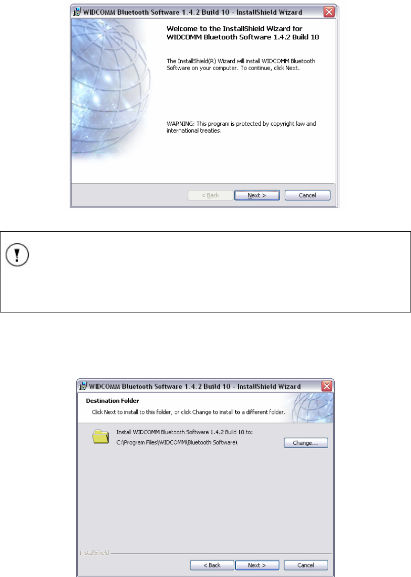
Installation Instructions
11049 Rev.2
- 4 -
3. Press Dongle BTW 1.4.10. The Bluetooth installation welcome screen will be
displayed.
4. Press Next to begin the Bluetooth driver installation.
Installation Screen Capture 2 Bluetooth installation welcome
NOTE
If you have not already installed your Bluetooth Dongle it is important to
do so now.
5. Click Next, the license agreement will appear. Read the agreement.
6. Press I accept the terms in the license agreement. The next window that
appears is the Destination Folder window. This window will allow you to choose
the folder on your computer where the driver files will be installed.
Installation Screen Capture 3 Destination
Installation Instructions
11049 Rev.2
- 5 -
7. Press Next to accept the current folder or press Change to change the
destination folder of the Bluetooth driver to a different folder.
8. Press Next. The next window that will appear is the installation review window.
Installation Screen Capture 4 Destination Folder
9. Press Install to begin the installation of your Bluetooth Driver. Installation window
will appear once the installation has begun.
Installation Screen Capture 5 Installing WIDCOMM
Installation Instructions
11049 Rev.2
- 6 -
10. When the files are being installed a Drive Signature Notice will be displayed.
Press Cancel to continue with the installation.
Installation Screen Capture 6 Driver Signature Notice
11. During the installation a warning window will appear stating “The software you
are installing has not passed Windows® Logo testing…” The Integrity™ software
requires this warning to be bypassed. Please press Continue Anyway.
Installation Screen Capture 7 Warning - Windows® Logo Testing
NOTE
Vivosonic Inc. has verified the compatibility of the Integrity™ software
with Windows XP®.
12. The InstallShield Wizard Complete window will be displayed once the driver is
completely installed. Press Finish to resume the Bluetooth configuration.
Rename a Windows® Bluetooth file.
The Bluetooth driver must be configured to be able to properly function with the
Integrity™ system.
Installation Instructions
11049 Rev.2
- 7 -
Once the initial driver has been installed a specific Windows® Bluetooth file bust be
renamed.
13. From the Windows® Start menu select Run.
Configuration Screen Capture 1 Start | Run menu
14. Enter %WINDIR%/INF
Configuration Screen Capture 2 Run Windows® INF directory
15. Press OK. The Windows® INF directory will open.
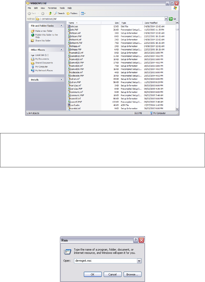
Installation Instructions
11049 Rev.2
- 8 -
Configuration Screen Capture 3 Windows® INF directory
16. Find the file called Bth.inf.
NOTE
The file Bth.inf may also be displayed as BTH if your system does not
display file extensions.
17. Right-click the file Bth.inf.
18. Select Rename. Rename this file Bth.bak.
19. Press Enter.
20. Close the window by selecting File | Close from the main menu on the top right
side of the window.
Update the Bluetooth driver
1. From the Windows® Start menu select Run. Refer to Configuration Screen
Capture 1.
2. This time type devmgmt.msc in the text field.
Configuration Screen Capture 4 Run Device Manager
3. Press OK. A directory listing the different device will display
Installation Instructions
11049 Rev.2
- 9 -
Configuration Screen Capture 5 Device Manger
4. Click the sign beside Bluetooth Devices to expand the list of options for
Bluetooth.
5. Right-click the first option under Bluetooth Devices, an options window will
open.
Configuration Screen Capture 6 Options window
6. Select Update Driver… from the options. The Found New Hardware window will
open.
Installation Instructions
11049 Rev.2
- 10 -
Configuration Screen Capture 7 New Hardware Window
7. Select Yes, this time only.
8. Press Next. The hardware wizard will continue the update.
NOTE
Windows® may choose the proper CSR USB Bluetooth driver to install
the files automatically when Next is pressed. If Windows® did install your
drivers automatically proceed to Bluetooth Services
Configure the Bluetooth Settings on page - 12 -
Installation Instructions
11049 Rev.2
- 11 -
Configuration Screen Capture 8 Install from specific location
9. Select Install from … a specific location (advanced).
10. Press Next. The next window will appear.
11. Select Don’t search. I will choose the driver to install and press Next.
Windows® will then scan for all compatible drivers for your Bluetooth device.
Once the scan is complete you will be given a list to choose from which may
consist of one or more drivers.
Installation Instructions
11049 Rev.2
- 12 -
Configuration Screen Capture 9 Device list
12. Select CSR USB Bluetooth Device and press Next.
The system will then begin to download all of the appropriate files for the new
Bluetooth Driver. Once the download and installation is complete, the
Completing the Found New Hardware Wizard window will be displayed.
13. Press Finished.
The Bluetooth device drivers are now installed.
Bluetooth Services
Configure the Bluetooth Settings
Once the Bluetooth driver has been installed it is important to properly configure the
setting.
1. From the Start menu select Control Panel. Refer to Configuration Screen
Capture 1 on page - 7 -
2. Once in Control Panel ensure that it is in Classic View (refer to Configuration
Screen Capture 11). If not then select Switch to classic view from the left of
the screen of the Category View (Refer to Configuration Screen Capture 10).
Installation Instructions
11049 Rev.2
- 13 -
Configuration Screen Capture 10 Control Panel - Category View
Configuration Screen Capture 11 Control Panel - Classic View
3. Select Bluetooth Configuration from the list in Control Panel (shown with a
circle in the figure above). The Initial Bluetooth Configuration Wizard will open.
Installation Instructions
11049 Rev.2
- 14 -
Configuration Screen Capture 12 Initial Bluetooth Configuration Wizard
4. Ensure all the boxes are checked.
5. Press Next. The Bluetooth general information will be displayed.
Configuration Screen Capture 13 Bluetooth general information
6. Ensure that the Computer name field contains the name of your computer and
that Computer type is properly selected (Windows XP® based computer).
7. Once your computer name is entered the Next button will become selectable.
8. Press Next.
9. The next step is to configure the services available for the Bluetooth. Press Next
on the service introduction page to display the services available.
Installation Instructions
11049 Rev.2
- 15 -
Configuration Screen Capture 14 Services available
10. The only service Integrity will require is the Bluetooth Serial Port. Ensure the
Bluetooth Serial Port service is selected with a check and that all of the other
services (including the ones not shown in the figure above) are not selected by
clearing their respective checkboxes.
11. Press Next. Windows® will now continue setting the options for Bluetooth. This
may take several minutes. Once the settings have been changed the following
window will appear.
Configuration Screen Capture 15 Configure services
12. Press Skip to continue.
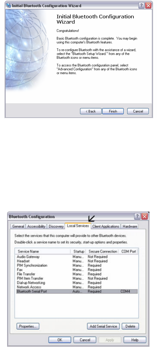
Installation Instructions
11049 Rev.2
- 16 -
Configuration Screen Capture 16 Congratulations
13. When the screen reads “Congratulations” the configuration of the Bluetooth
driver and setting is complete.
14. Press Finish to close the Bluetooth Configuration Wizard.
Bluetooth Security Settings
1. From the Start menu select Control Panel. Refer to Configuration Screen
Capture 1 on page - 7 -
2. Select Bluetooth Configuration from the list in Control Panel (shown with a
circle in the Configuration Screen Capture 11). This time the Bluetooth
Configuration window will open.
3. Select the Local Services tab.
Configuration Screen Capture 17 Configuration - local services
4. Highlight Bluetooth Serial Port and press the Properties button on the lower
left-hand side of the window. The Bluetooth Properties dialog window will open.
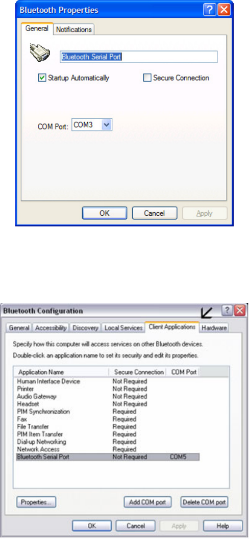
Installation Instructions
11049 Rev.2
- 17 -
Configuration Screen Capture 18 Local Services properties dialog
5. Ensure the: Startup Automatically is checked and that the Secure Connection
checkbox is not selected.
6. Press Apply and then press OK. This will close the properties dialog and return
the Bluetooth Configuration window.
Configuration Screen Capture 19 Configuration - client services
7. Select the Client Applications tab.
8. Highlight Bluetooth Serial Port and press the Properties. The properties dialog
window will open.
Installation Instructions
11049 Rev.2
- 18 -
Configuration Screen Capture 20 Client services properties dialog
9. Ensure that Secure Connection checkbox is not selected.
10. Press Apply and then press OK. This will close the properties dialog and return
the Bluetooth Configuration window. Refer to Configuration Screen Capture 19.
11. Press OK to close the Bluetooth Configuration window.
This completes the Bluetooth hardware and software configuration for Integrity.
Integrity
This section of the installation will deal with installing the Integrity system software on the
computer.
1. Remove the CD labeled Integrity from its sleeve and place it in the CD tray in
the computer.
2. Wait a few seconds for the CD to auto load.
If it does not automatically load select Start | My Computer from the bottom left
corner of Windows®. Double-click on the CD drive and this will open the directory
containing the following files.
Configuration Screen Capture 21 Files on Integrity CD
Installation Instructions
11049 Rev.2
- 19 -
3. Double-click Setup.exe to open the InstallShield Wizard and begin the
installation.
4. Before the InstallShield starts installing Integrity it first confirms that two required
files are on the computer. Refer to Configuration Screen Capture 22.
Configuration Screen Capture 22 Confirm required software
5. Press OK. The InstallShield will begin installing the two required files.
The first install is the Bluetooth Configuration files which will add certain files to
your system used by Integrity’s main install.
Configuration Screen Capture 23 Bluetooth configuration files
Once the files have been installed the InstallShield prompt for the Microsoft SQL
Server 2000 Desktop Engine (MSDE) install to start.
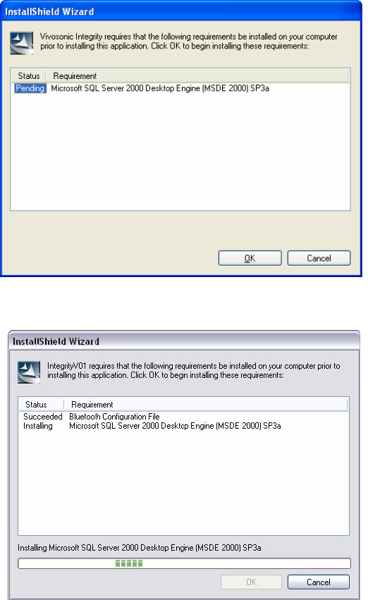
Installation Instructions
11049 Rev.2
- 20 -
Configuration Screen Capture 24 MSDE install start
6. Press OK.
Configuration Screen Capture 25 MSDE initialization
7. Once MSDE has initialized, it will begin to install onto your machine.
8. When the installation is complete the computer will reboot.
9. Once the computer has finished rebooting, Integrity will initialize for its
installation.
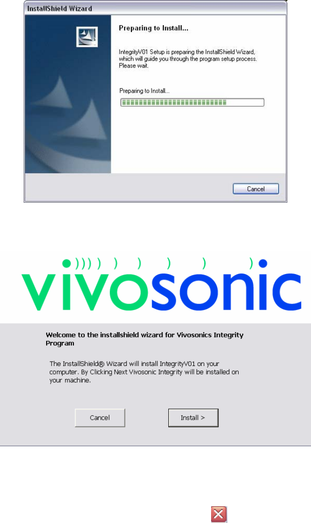
Installation Instructions
11049 Rev.2
- 21 -
Configuration Screen Capture 26 Integrity initialization
10. When the initialization is complete the Vivosonic welcome screen will be
displayed.
Configuration Screen Capture 27 Vivosonic welcome
11. Press Install.
12. When the installation is almost complete the SQL Server Service Manager will
launch.
The SQL Server window can be closed using the at the top-right corner of
the window.
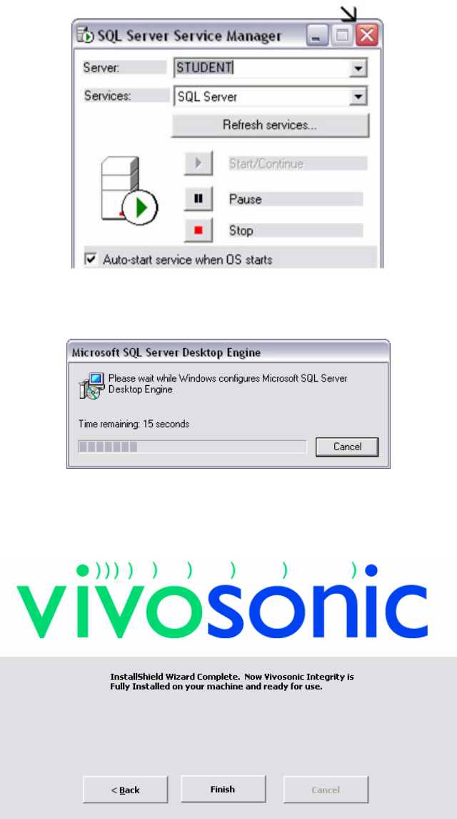
Installation Instructions
11049 Rev.2
- 22 -
Configuration Screen Capture 28 Close SQL Server
13. When SQL Server Service Manager has been launched a second application
(Jet to MSDE) will quickly install and close.
Configuration Screen Capture 29 MSDE installation
Once the Microsoft SQL Server Desktop Engine has finished running Vivosonic
InstallShield Wizard Complete screen will be displayed. Integrity is now installed on the
computer.
Configuration Screen Capture 30 Vivosonic InstallShield wizard complete
Establishing a Connection
The wireless connection between VivoLink and the Integrity system must be established.
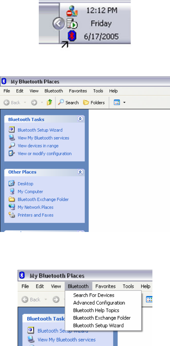
Installation Instructions
11049 Rev.2
- 23 -
1. Turn on the VivoLink.
2. Double-click the Bluetooth icon on your Windows® taskbar.
Configuration Screen Capture 31 Bluetooth icon
3. The Bluetooth Places window will open.
Configuration Screen Capture 32 Bluetooth places
4. Select Bluetooth from the main menu. A drop-down list of options will be
displayed.
5. Select Search for Devices.
Configuration Screen Capture 33 Bluetooth options
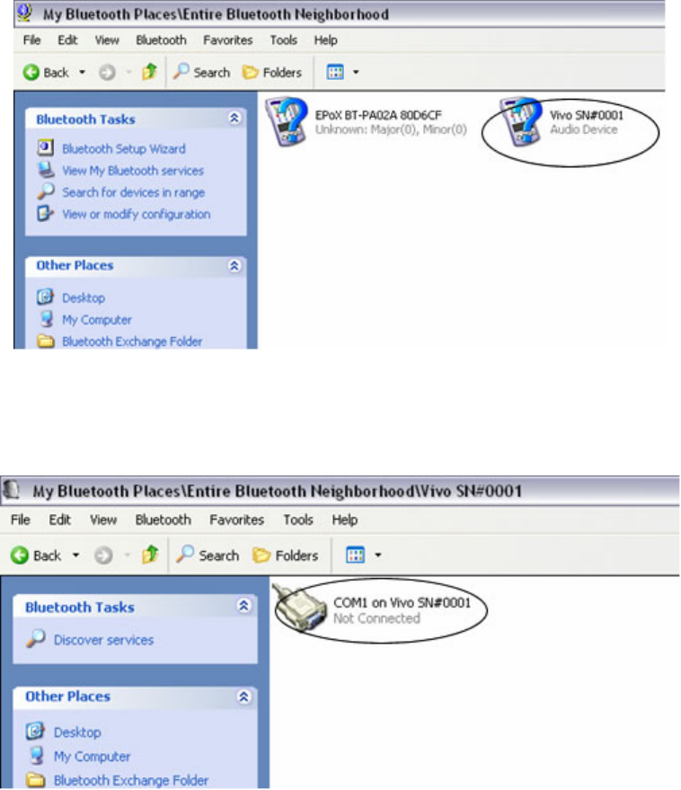
Installation Instructions
11049 Rev.2
- 24 -
6. Windows® will begin to look for all Bluetooth Devices. Once Windows® has
finished checking for all Bluetooth devices, the VivoLink device should appear.
If it does not appear, ensure that the VivoLink is turned on and has sufficient
battery power.
Configuration Screen Capture 34 VivoLink device found
7. VivoLink should appear with the following name:
Vivo SN#XXXX where XXXX is the serial number.
8. Double-click the VivoLink icon. The VivoLink directory will open.
Configuration Screen Capture 35 VivoLink directory
9. Double-click the icon labeled COM1 on Vivo SN#XXXX.
The system will attempt to connect to the VivoLink. A Connecting message will
be displayed at the bottom left-hand corner of the screen. In the Windows®
taskbar (bottom right corner) a bubble will appear on the Bluetooth icon.
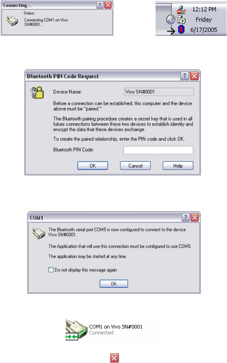
Installation Instructions
11049 Rev.2
- 25 -
Configuration Screen Capture 36 Connecting window and taskbar
10. Double-click the Bluetooth icon in the taskbar. The Bluetooth PIN Code
Request window will open.
Configuration Screen Capture 37 PIN code request
11. Enter the Bluetooth PIN code - 5150.
12. Press OK. The COM1 window will open.
Configuration Screen Capture 38 COM1
13. Press OK. The connecting window will show the message “Connected”.
Configuration Screen Capture 39 Connected
14. Close this window using the red X ( ). The Integrity system is ready to be
used.

Installation Instructions
11049 Rev.2
- 26 -
Calibration Files Installation Instructions
Requirements
The Integrity system installation instruction must be completed first. If the Integrity system
cannot connect to the VivoLink because Integrity has not been installed, please go back
and complete this process first. Refer to page - 2 -
CAUTION:
Possible loss of calibration files
This procedure will overwrite calibration files that already exist on the
Integrity V500 system. Before beginning this installation it is
recommended that the current file directory is backed up. Make a copy of
the following file directory:
C:\Integrity V1.0\Calibration Data\”
Instructions
1. Make sure that the Integrity V500 software is not currently running.
2. Place the Calibration CD into the CD ROM.
3. Copy ALL files from the Calibration CD to the following directory on the Integrity
V500 computer:
C:\Integrity V1.0\Calibration Data\
4. Restart the computer. The new calibration files will not be used until the
computer is restarted.