Voxx Electronics DEI7752 Hand Held Security/Remote Control Transceiver User Manual page 1 to 20
DEI Headquarters, Inc. Hand Held Security/Remote Control Transceiver page 1 to 20
Contents
- 1. user manual page 1 to 20
- 2. user manual pages 1 to 20
- 3. user manual page 21
- 4. user manual pages 22 to 30
- 5. user manual page 31 to 54
user manual page 1 to 20

Model ????
Security and Remote Start
Owner’s Guide
© 2008 Directed Electronics, Vista, CA
G5902V 2008-03

Contents
Government regulations .....................................................................................5
Warning! safety first ..........................................................................................7
What is included ...............................................................................................9
Important information ........................................................................................9
Your warranty...........................................................................................9
Replacement remotes...............................................................................10
Caution .................................................................................................10
Responder LC 2-Way .......................................................................................11
Responder LC 1-way ........................................................................................12
Transmitter configuration ..........................................................................13
System maintenance ...............................................................................19
Charging the Battery ...............................................................................19
Low battery indicator ..............................................................................20
Battery Replacement ................................................................................20
LCD Iayout .............................................................................................21
LCD remote features ................................................................................21
Multi-car control capability ......................................................................22
Using the system .............................................................................................23
Arming the system...................................................................................23
While the system is armed .......................................................................24
Modified Arming Modes..........................................................................26
Disarming the System ..............................................................................28
System override ......................................................................................28
Using the remote start ......................................................................................30
Before using your Remote Start .................................................................30
Remote starting your vehicle .....................................................................30
Points to remember .................................................................................30
Runtime Check .......................................................................................31
Manual transmission ...............................................................................31
Timer mode ............................................................................................32
Turbo timer mode ....................................................................................32
Safety features ...............................................................................................35
Starter anti-grind circuitry .........................................................................35
Disabling the remote start system ..............................................................35
Diagnostics ....................................................................................................36
Arming .................................................................................................36
Disarming .............................................................................................37
System status chirps ...............................................................................37
Table of zones ........................................................................................38
Interpreting zone diagnostics ....................................................................38
Nuisance prevention® circuitry ................................................................39
Owner recognition ............................................................................................................. 40
Rapid resume logic ..........................................................................................40
Power saver mode...........................................................................................41
System...................................................................................................41
2-way remote .........................................................................................41
Programming options .......................................................................................42
Security & convenience expansions ...................................................................44
Glossary of terms ............................................................................................46
Quick reference guide .....................................................................................49
Limited lifetime consumer warranty ....................................................................51

5
© 2008 Directed Electronics. All rights reserved.
Government regulations
This device complies with Part 15 of FCC rules. Operation is subject to the fol-
lowing two conditions: (1) This device may not cause harmful interference, and
(2) This device must accept any interference received, including interference that
may cause undesirable operation.
This equipment has been tested and found to comply with the limits for a class B
digital device, pursuant to Part 15 of the FCC Rules. These limits are designed to
provide reasonable protection against harmful interference in a residential instal-
lation. This equipment generates and can radiate radio frequency energy and,
if not installed and used in accordance with the instruction manual, may cause
harmful interference to radio communications. However, there is no guarantee
that interference will not occur in a particular installation. If this equipment does
cause harmful interference to radio or television, which can be determined by
turning the equipment OFF and ON, the user is encouraged to try to correct the
interference by one or more of the following measures:
• Reorient or relocate the receiving antenna.
• Increase the separation between the equipment and receiver.
• Connect the equipment into an outlet on a circuit different from that to which
the receiver is connected.
• Consult the dealer or an experienced radio / TV technician for help.
To satisfy FCC RF exposure compliance requirements, this device should be used
in hand-held, hand operated configurations only. The device and its antenna
must maintain a separation distance of 20 cm or more from the person’s body,
except for the hand and wrists, to satisfy RF exposure compliance. This device
is designed to be used in a person’s hands and its operating configurations do
not support normal transmissions while it is carried in pockets or holsters next to
a persons’ body.
This device complies with the Industry Canada Radio Standards Specification
6© 2008 Directed Electronics. All rights reserved.
RSS 210. Its use is authorized only on a no-interference, no-protection basis; in
other words, this device must not be used if it is determined that it causes harm-
ful interference to services authorized by IC. In addition, the user of this device
must accept any radio interference that may be received, even if this interference
could affect the operation of the device.
Warning:
Changes or modications not expressly approved by the party responsible for
compliance could void the user’s authority to operate this device.

7
© 2008 Directed Electronics. All rights reserved.
Warning! safety first
The following safety warnings must be observed at all times:
Due to the complexity of this system, installation of this product must only be
performed by an authorized Directed dealer.
When properly installed, this system can start the vehicle via a command signal
from the remote control transmitter. Therefore, never operate the system in an
enclosed area or partially enclosed area without ventilation (such as a garage).
When parking in an enclosed or partially enclosed area or when having the
vehicle serviced, the remote start system must be disabled using the installed
toggle switch. It is the user’s sole responsibility to properly handle and keep out
of reach from children all remote control transmitters to assure that the system
does not unintentionally remote start the vehicle. THE USER MUST INSTALL A
CARBON MONOXIDE DETECTOR IN OR ABOUT THE LIVING AREA ADJA-
CENT TO THE VEHICLE. ALL DOORS LEADING FROM ADJACENT LIVING
AREAS TO THE ENCLOSED OR PARTIALLY ENCLOSED VEHICLE STORAGE
AREA MUST AT ALL TIMES REMAIN CLOSED. These precautions are the sole
responsibility of the user.
Remote starters on manual transmission vehicles operate differently than those
with automatic transmission
because you must leave your car in neutral. You
must read this Owner’s Guide to familiarize yourself with the proper procedures
regarding manual transmission remote starters. If you have any questions, ask
your installer or contact Directed at 1-800-753-0600.
Before remote starting a manual transmission vehicle, be sure to:
Leave the vehicle in neutral and be sure no one is standing in front or •
behind the vehicle.
Only remote start on a flat surface•
Have the parking brake fully engaged•

8© 2008 Directed Electronics. All rights reserved.
WARNING!
It is the responsibility of the owner to ensure the parking/
emergency brake properly functions. Failure to do so can result in
personal injury or property damage. We recommend the owner have
the parking / emergency brake system inspected and adjusted by a qualied
automotive shop bi-annually.
Use of this product in a manner contrary to its intended mode of operation may
result in property damage, personal injury, or death. (1) Never remotely start the
vehicle with the vehicle in gear, and (2) Never remotely start the vehicle with
the keys in the ignition. The user must also have the neutral safety feature of the
vehicle periodically checked, wherein the vehicle must not remotely start while
the car is in gear. This testing should be performed by an authorized Directed
dealer in accordance with the Safety Check outlined in the product installation
guide. If the vehicle starts in gear, cease remote start operation immediately and
consult with the authorized Directed dealer to x the problem.
After the remote start module has been installed, contact your authorized dealer
to have him or her test the remote start module by performing the Safety Check
outlined in the product installation guide. If the vehicle starts when performing
the Neutral Safety Shutdown Circuit test, the remote start unit has not been
properly installed. The remote start module must be removed or the installer must
properly reinstall the remote start system so that the vehicle does not start in gear.
All installations must be performed by an authorized Directed dealer.
OPERATION OF THE REMOTE START MODULE IF THE VEHICLE STARTS IN
GEAR IS CONTRARY TO ITS INTENDED MODE OF OPERATION. OPERAT-
ING THE REMOTE START SYSTEM UNDER THESE CONDITIONS MAY RESULT
IN PROPERTY DAMAGE OR PERSONAL INJURY. YOU MUST IMMEDIATELY
CEASE THE USE OF THE UNIT AND SEEK THE ASSISTANCE OF AN AU-
THORIZED Directed DEALER TO REPAIR OR DISCONNECT THE INSTALLED
REMOTE START MODULE. DIRECTED WILL NOT BE HELD RESPONSIBLE OR
PAY FOR INSTALLATION OR REINSTALLATION COSTS.

9
© 2008 Directed Electronics. All rights reserved.
What is included
The control module with Stinger™DoubleGuard®two-stage shock •
sensor
Control center (installed out of sight on your vehicle) with inte-•
grated status LED and Valet override switch
One ve-button/2-way Supercode Responder LE Remote Control •
One ve-button/ 1-way Supercode remote•
Revenger™Soft Chirp™six-tone siren•
A shut-down toggle switch•
Window decals•
Your warranty registration•
Important information
Congratulations on the purchase of your state-of-the-art remote start and
alarm system. Due to the complexity of this system, it must be installed
by an authorized dealer only. Installation of this product by anyone
other than an authorized dealer voids the warranty. All dealers are
provided with a preprinted dealer certificate to verify authorization.
By carefully reading this Owner’s Guide prior to using your system,
you will maximize the use of this system and its features. You can print
additional or replacement copies of this manual by accessing our web
site at www.directed.com.
➤ Your warranty
Your warranty registration must be completely filled out and returned
within 10 days of purchase. Your product warranty will not be validat-
ed if your warranty registration is not returned. Make sure you receive
the warranty registration from your dealer. It is also necessary to keep
10 © 2008 Directed Electronics. All rights reserved.
your proof of purchase, which reflects that the product was installed by
an authorized dealer.
➤ Replacement remotes
Your system comes with one Responder LE remote control (P/N 7752V)
and one companion remote control (P/N 7652V). If additional remotes
are desired, please see your authorized dealer or visit www.directed-
store.com to order.
➤ Caution
This product is designed for fuel injected vehicles only. Use of this
product in a standard transmission vehicle must be in strict accordance
with this guide.
11
© 2008 Directed Electronics. All rights reserved.
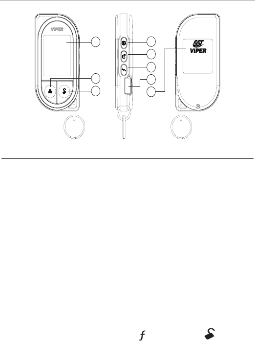
Responder LC 2-Way
5319
,&$
)&&,'(=6'(,
531;
,&$
)&&,'(=6'(,
5313
,&$
)&&,'(=6'(,
1
2
3
4
5
6
7
8
1
2
3
4
5
6
7
8
1
2
3
4
5
6
7
8
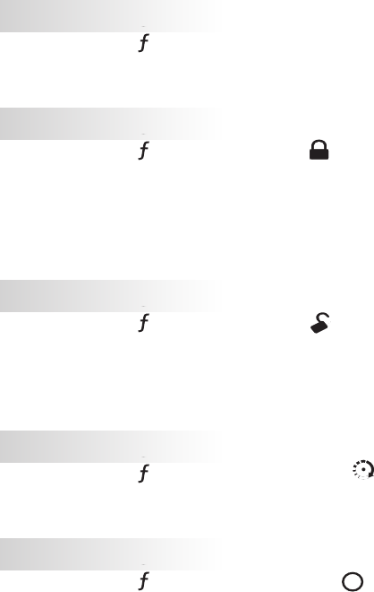
Feature Description
1 LCD
2 Lock button Press for one second to arm.
3 Unlock button Press for one second to disarm.
4Auxiliary button Press and hold for 1.5 second to activate
optional trunk release.
5 Remote start button Press for one second to activate remote
start.
6 Function button Allows access to programming and modi-
fies operation of the other buttons.
7 Charge Port Plug in the battery charger to this port.
8 Label Back of remote has label to identify the
remote as 2-way or 1-way.
9 Battery Door For accessing batteries when necessary.
Note:
If Keypad Lock is On, press
A U X
and then press
A U X
to exit.

12 © 2008 Directed Electronics. All rights reserved.
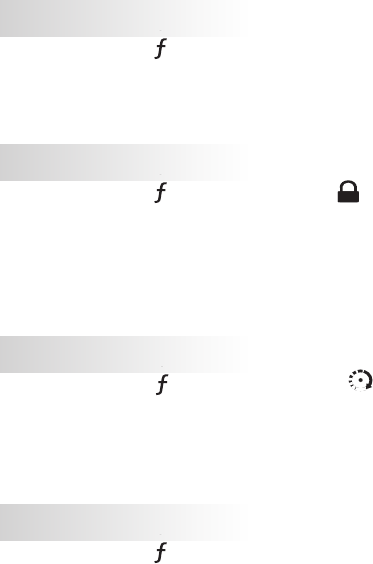
Responder LC 1-way
Feature Description
1Transmit indicator
2Lock button Press for one second to arm.
3Unlock button Press for one second to disarm.
4Remote start
button
Press for one second to activate remote
start.
5Auxiliary
button
Press and hold for 1.5 second to activate
trunk release.
6Function
button
Allows access to programming and
modifies operation of the other buttons.
71 WAY Label Back of remote has label to identify the
remote as 2-way or 1-way
8Battery Door Remove to access batteries when neces-
sary. For more details, see p.10
Note:
If Keypad Lock is On, press
A U X
and then press
A U X
to exit.
13
© 2008 Directed Electronics. All rights reserved.
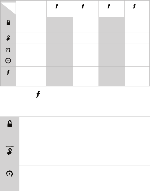
➤ Transmitter configuration
Button
Level Direct
Access
A U X
x 1
A U X
x 2
A U X
x 3
A U X
x 4
A U X
ARM/LOCK
(Panic)
SILENT ARM SENSOR
BYPASS
SILENT ALARM
SENSORS
SILENT ALARM
ALL ZONES
A U X
DISARM/UNLOCK
(Panic)
SILENT DISARM VALET ON/OFF CAR FINDER
A U X
STARTER
ON/OFF
RESET RUNTIME TIMER MODE
ON/OFF
SMART START
ON/OFF
DEFOGGER ON
A U X
TRUNK RELEASE
(Red/White)
AUX 1 AUX 2 AUX 3
A U X
Advance Level
Change Car (3s)
Enter program-
ming (8s) *
REQUEST TEM-
PERATURE *
RUNTIME
REMAINING *
EVENT HISTORY
REPORT *
* button must be pressed and held to access state.
Button
A U X
Arm
Command
:
Press one time to Arm
Feedback
:
Lock Icon will appear, and one beep from remote
Notes
:
Press/hold for 1.5 seconds to Arm the system and then acti-
vate the Panic output
A U X
Disarm
Command
:
Press one time to Arm
Feedback
: Unlock icon appears and remote beeps twice
Notes
:
A U X
Remote
Start
Command
: Press one time to activate Remote Start
Feedback
:
Remote Start Icon appears on screen. remote emits a tone
Notes
:

14 © 2008 Directed Electronics. All rights reserved.
A U X
AUX
Command
: Press and hold for 1.5 seconds to activate the Trunk Re-
lease.
Feedback
: The trunk icon appears and the remote plays a short tone.
Notes
: This is an optional feature. See your sales rep/installer for
details.
A U X
Function
Shift
Command
: Press 1 to 4 times. ( See Function shift table.)
Feedback
: Display shows a text message across the bottom for the com-
mand received.
Notes
: Each Press then release, shifts the function of the command
button.
Pressing more than one button simultaneously generates an Error tone
and the F-Shift LED turns ON.
15
© 2008 Directed Electronics. All rights reserved.
Feature List:
Silent arm
Command
: Press
A U X
one- time and then press
A U X
Feedback
: Screen changes to the lock icon
Notes
: Arms the system without chirps
Silent disarm
Command
: Press
A U X
one- time and then press
A U X
.
Feedback
: Screen changes to unlock icon
Notes
: Disarms the system without chirps
Runtime reset
Command
: Press
A U X
one-time and then
A U X
.
Feedback
: Remote start ON tones.
Notes
: Re-starts the remote start runtime counter if remote start
is active. Note: If remote start is not active, the 2-WAY
remote will respond with error tone.
Aux 1
Command
: Press
A U X
one time and then press
A U X
.
Feedback
: The screen will show a text of the item activated
Notes
: This is an optional feature. See your sales rep/installer
for details.
Cabin temperature
Command
: Press
A U X
one time, then Hold for 1.5 seconds.
Feedback
: Screen will display current in cabin temperatue.
Notes
: Cabin temperature is displayed on the remote. LED lights
up to indicate a range.
16 © 2008 Directed Electronics. All rights reserved.
Sensor Bypass
Command
: Press
A U X
two- times and then
A U X
Feedback
: Screen will display text of sensor bypass
Notes
: Available when armed only: bypasses warn triggers.
Send again to bypass Warn & Full Trigger; Send again
to turn bypass off and monitor sensors normally. For more
information, see Modified Arming Modes.
Valet mode
Command
: Press
A U X
two-times and then
A U X
.
Feedback
: Unlock Icon appears hollow and text states Valet when
entering Valet mode.
Unlock Icon appears solid and text states Valet when
exiting Valet mode
Notes
: To enter or exit Valet mode, even if Armed. When enter-
ing Valet Mode the unlock LED blinks, and the remote
beeps one time. When exiting Valet Mode the unlock
LED blinks and the remote beeps two-times.
Timer mode
Command
: Press
A U X
two-times and then
ALL
.
Feedback
: Small timer icon appears and text reads timer mode.
Notes
: Enables or disables the remote start timer mode.
Aux 2
Command
: Press
A U X
two times and then press
A U X
.
Feedback
: Text will display the item activated
Notes
: This is an optional feature. See your sales rep/installer
for details.
17
© 2008 Directed Electronics. All rights reserved.
Armed status
Command
: Press
A U X
two-times and then Hold for 1.5 seconds.
Feedback
: Icon on remote will flash showing current status
Notes
: Replays last Arm /Disarm status message received.
Armed (silent sensor mode)
Command
: Press
A U X
three- times and then
A U X
Feedback
: Image of hollow siren appears and text reads Silent Sen-
sor.
Notes
: Arms the system; sensor Full Trigger will ONLY page the
remote and will not activate the siren/lights. Wired in-
puts will page and activate the siren/lights.
Car finder
Command
: Press
A U X
three-times and then
A U X
.
Feedback
: Icon of vehicle ashes and text reads car nder. On
Vehicle: 1 long siren chirp and parking lights ash 10
times.
Notes
: Arm/Disarm cancels the light ashes.
Smart start
Command
: Press
A U X
three-times and then press
A U X
.
Feedback
: Text reads Smart Start On
Notes
: Enables or disables the SmartStart feature.
Aux 3
Command
: Press
A U X
three times and then press
A U X
.
Feedback
: Text will display the item activated
Notes
: This is an optional feature. See your sales rep/installer
for details.
18 © 2008 Directed Electronics. All rights reserved.
Runtime check
Command
: Press
A U X
three-times, and then Hold for 1.5 seconds.
Feedback
: Text reads runtime and displays time left
Notes
: Runtime remaining is displayed on the remote. (See
page 28).
Armed (silent trigger mode)
Command
: Press
A U X
four- times and then
A U X
.
Feedback
: Text displays Silent Full
Notes
: Arms the system; sensor and hardwire Full Triggers will
ONLY page the remote and will not activate the siren/
lights. For more details see Silent Mode 2 section on
page 25.
Rear defogger
Command
: Press
A U X
four times, and then
A U X
. (Only after remote
start is on.)
Feedback
: Defogger icon appears on remote and text reads Defrost
On.
Notes
: Automatically turns on during remote start.
Last trigger
Command
: Press
A U X
four- times and then hold for 1.5 seconds.
Feedback
: Text scrolls last trigger.
Notes
: Trigger refers to the remote tones and LED pattern gener-
ated by the last alarm trigger event.
19
© 2008 Directed Electronics. All rights reserved.
Out of Range Notification
If a command is issued from the remote, but the remote is beyond the
range of the vehicle to receive the command, the remote will respond
with an Out of Range notification. If this occurs, the remote will emit a
harsh tone and the out of range indicator will appear.
Since conditions will vary in different areas (ie: Weather, RF interfer-
ence, etc) range may be affected and require you to be closer to the
vehicle for successful transmission.
➤ System maintenance
The system requires no specific maintenance. Your One way remote is
powered by small coin cell lightweight 3-volt lithium battery that will last
approximately one year under normal use. The 1-way remote uses one
CR2032 cell battery. The 2-way remote contains a non-replaceable
rechargeable battery. When the battery begins to weaken, the operat-
ing range will be reduced.
➤ Charging the Battery
Plug in the USB charger (alternately a standard mini USB cable •
connected to any standard USB port on any laptop or desktop
computer can also be used (cable not included)).
The LCD displays “CHARGE” while the battery level bars within •
the battery icon flash, displaying the current charge level as the
battery charges.
When charging is complete the LCD then displays “FULL”. •
Note:
If the battery has been severely discharged all remote functions
are disabled for a short charge period. The battery status outline flashes

20 © 2008 Directed Electronics. All rights reserved.
and CHARGE is displayed on the LCD. Once the battery has accu-
mulated enough charge for functionality, the LCD icons initialize with
a beep sound, the battery status outline stops flashing and the remote
becomes operational while still displaying CHARGE.
Satmode,
bank selector
AUDIO
PWR
12
REWFF
PLAY/PROG NR
3456
DISC- DISC+
11:53
XM1-1 CH-001
CH
VOL
SCAN SOUND
AM/FM
CD/AUX
SAT
RADIO
SEEK
SKIP
RPT
DISP -
MODE
A.SEL
RDM
TUNE
AUTO
OFF
DUAL
A/C MODE
Channel control
Category
Control
Text selector.
Hold for 10secto toggle
channelor category
tune modes.
Toggles
Scan mode
Bank and
present
indicator
Channel
and text
indicator
Preset 1-6.
Hold until beepto
savetoapreset.
CATEGORY
Tune mode
indicator
MODE
DUAL
OFF
AUTO
MAP/
GUIDE MENU SETUP
INFO ZOOM CANCEL AUDIO
AUTO
MODE
A/C
LOAD
DISC
TAPE AM/FM DISP
MODE
SCAN RPT A.SEL/RDM-SEEK +
1234 56
DISC- DISC+
VOL
PWR
PUSH
TUNE
SOUND
PUSH
XM1-1
VOL
CH
CHANNEL
CATEGORY
NAME
TITLE
:
:
:
:
1
CH
2
CH
3
CH
6
CH
5
CH
4
CH
MODE SCAN SOUND
001-HITS1
POP
MUSICNAME
MUSIC TITLE
Channel control
Category
Control
001 014 018
040 065 115
Toggles between
channel and
category modes
Bank and
present
indicator
Upper display
text mode
selector
Sat mode
and bank
selector
Preset 1-6.
Press until
beepto save
to a preset.
Channeland text
Indicator fields
Toggles
Scan mode
Tune mode
indicator
ANTENNA
SC OUTPUT
Sirius-Ready, SAT Radio Ready or select OEM headunits with optional Honda Bus Compatible Translator
Headunit bus cableSiriusConnect Cable
HON-SC1
Honda Bus
Compatible
Translator
Warning! The temperature range over which
the battery can be charged is 0ºC TO 45ºC
(32ºF TO 113ºF). Charging the battery at
temperatures outside this range may cause
severe damage to the battery or reduce bat-
tery life expectancy.
➤ Low battery indicator
When the batteries are low on the 2-way remote it will emit two groups
of beeps, the battery icon will ash and the text will display low batt,
the alarm then emits an additional chirp upon disarming of the alarm to
let you know its time to change the battery. When the battery is low on
the 1-way remote, the remote responds the same, but without the icons
available on the two way remote.
Note:
The Arm/Disarm chirps should be programmed ON for the
alarm to emit any additional chirps during disarm. Ask your autho-
rized dealer if you have any questions.
➤ Battery Replacement
Slide the door up to expose the battery beneath the holder. Remove the
expired battery. Place the new battery into the remote control. When
power is returned the remote control is ready for use.