Wave Wireless Networking SL9101A Spread Spectrum Transmitter User Manual USERS MANUAL 2
Wave Wireless Networking Spread Spectrum Transmitter USERS MANUAL 2
Contents
- 1. USERS MANUAL 1
- 2. USERS MANUAL 2
- 3. USERS MANUAL 3
USERS MANUAL 2
SPEEDLAN 9000 Series Installation and Operation User Guide Version 3.03
Using the Configurator to Set Up Special Parameters for CPE Routers 5-3
•Interface Type: Select the CPE from the Interface Type drop-down list. When
finished, click Apply. This will tell the configurator that you are in CPE mode.
•Network Name: The type of network for the wireless or fixed router.
•Enable Forwarding: Select the Enable Forwarding option to enable the
forwarding of IP packets from the wired interface to the wireless interface and
vice-versa.
•Disable Forwarding: Select the Disable Forwarding option to disable the
forwarding of IP packets from the wired interface to the wireless interface and
vice-versa.
•Apply: Click after making changes.
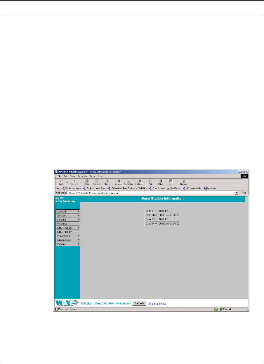
Base Station Information
To see if a CPE is connected to the base station, choose Base Station Info from the
Network menu. The following page will appear. Note: If there is no connection to the
base station, a message will appear confirming that the CPE is not connected to the
base station.
Figure 5-2: Base Station Information (for CPE mode)
Version 3.03 SPEEDLAN 9000 Series Installation and Operation User Guide
5-4 Using the Configurator to Set Up Special Parameters for CPE Routers
Authentication
Normally, the CPE routers must prove their authenticity with a base station before
participating in the star network. One way to do this is to set a common pass on both
the CPE router and on the base station. Use this page (Authentication Settings) to set a
pass phrase for a CPE router. You are only required to do this once, unless the pass
phrase on the base station changes. Just make sure that the password is kept in a safe
place so it is not lost or stolen.
All interfaces connected to the 9000 router are restricted to systems based on the
authentic pass phrase (or password). Any interface that does not have the correct pass
phrase will not be able to establish a data connection.
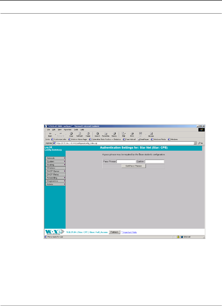
To authenticate a CPE, choose Authentication from the Network menu. The
following page will appear.
Figure 5-3: Authentication Settings for CPE page
•Pass Phrase: Enter a pass phrase and confirm it like setting up a regular
password. As shipped there would be a blank pass phrase and a base station
authenticates CPE routers using the MAC address. If you want to use the Pass
Phrase authentication, then you have to set matching pass phrases on a base

SPEEDLAN 9000 Series Installation and Operation User Guide Version 3.03
Using the Configurator to Set Up Special Parameters for CPE Routers 5-5
station and on a CPE. (Pass Phrases have a minimum of 8 characters and a
maximum of 32 characters.)
•Confirm: Enter the pass phrase again to ensure it is correct. Make sure you
keep the pass phrase in a safe place.
Wireless menu
Choose Configuration from the Wireless menu and you will be able to choose one of
the following:
•If you click the Channel and Rates button, you will be able to select the
channel and signaling rate of the interface. For more information, see
Channel and Rates, page 5-6.
•If you click the Tx Retries button, you will be able to set the Transmit Retry Limit
and Signaling Rate Fallback. For more information, see Max Tx Retries and
Signaling Rate Fallback, page 5-8.
•If you click the Max Throughput button, you will be able to set the Max
Transmit Data Rate in Kb/s. For more information, see Max Throughput
(Regulating Bandwidth), page 5-10.
Version 3.03 SPEEDLAN 9000 Series Installation and Operation User Guide
5-6 Using the Configurator to Set Up Special Parameters for CPE Routers
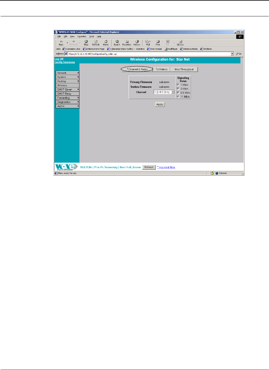
Channel and Rates
Figure 5-4: Channel and Rates page
•Primary Firmware: This is the current primary firmware version in use by the
wireless card.
•Station Firmware: This is the current station firmware version in use by the
wireless card.
•Channel: This is the specific band of frequencies (from 1 to 11) to determine
the data path between routers. All SPEEDLAN 9000 routers expected to
communicate in a network must have the same channel (frequency). Select
one of the following channels (all are represented in GHz) from the Channel
drop-down list:
12.412
22.417
32.422
42.427
52.432
62.437
72.442
version: v

SPEEDLAN 9000 Series Installation and Operation User Guide Version 3.03
Using the Configurator to Set Up Special Parameters for CPE Routers 5-7
82.447
92.452
10 2.457
11 2.462
•Signaling Rate: This setting refers to the wireless signaling rate. The
SPEEDLAN 9000 routers have four signaling rates that can be used. Select
one of the following check boxes:
•1 Mb/s: This setting limits the card by providing 1 Mb/s of bandwidth.
The minimum receiver sensitivity of the radio with this setting is -92 dBm.
•2 Mb/s: This setting limits the card by providing 2 Mb/s of bandwidth.
The minimum receiver sensitivity of the radio with this setting is -89 dBm.
•5.5 Mb/s: This setting limits the card to providing 5.5 Mb/s of
bandwidth. The minimum receiver sensitivity of the radio with this setting is
-88 dBm.
•11 Mb/s: This is the full 11 Mb/s signaling rate. This value is
recommended for most installations. The minimum receiver sensitivity of
the radio with this setting is -85 dBm.
Note: The network can automatically downgrade the bandwidth if needed (that is, if
lower Mb/s settings are selected). Click Apply when finished.

Version 3.03 SPEEDLAN 9000 Series Installation and Operation User Guide
5-8 Using the Configurator to Set Up Special Parameters for CPE Routers
Max Tx Retries and Signaling Rate Fallback
This page includes two features: Max Tx Retries and Signaling Rate Fallback. On the
figure below, Max Tx Retries is circled in red and Signaling Rate Fallback is circled in
blue. The following page appears when the Tx Retries button is clicked:
Figure 5-5: Tx Retries and Signaling Rate Fallback page
Note: Click Apply to activate settings.
Max Tx Retries
Wave Wireless recommends that you use this parameter to increase the throughput of
your wireless network. This parameter tells a network node the maximum number of
times a unicast frame can be retransmitted before it is discarded. (A unicast frame is
one that is transmitted to a single node in a network.) This allows a network manager to
tune a network for its particular topology and expected traffic characteristics. The
network topology, RF environment, number of nodes, throughput requirements, latency
requirements, and type of applications are all factors in choosing an appropriate value
for this parameter.

SPEEDLAN 9000 Series Installation and Operation User Guide Version 3.03
Using the Configurator to Set Up Special Parameters for CPE Routers 5-9
This parameter can be tuned on a per unit basis in order to optimize network
performance. Click Default to get the default value of 7. You can select a value
between 0 and 8 from the Max Tx Retries drop-down list.
Signaling Rate Fallback
During the retransmission of a unicast frame, the signaling rate can "fall back" in order
to increase the chance of reception. Signaling Rate Fallback can occur multiple times
for a single frame. Signaling Rate Fallback occurs from the current rate and will only
include those signaling rates selected on the Channel and Rates page. After ten
consecutive successful unicast frames, the current rate is restored to the highest
selected rate.
The Signaling Rate Fallback parameter allows you to control when the signaling rate
will drop, depending on the check box(es) you selected. That is, the check box(es)
labeled, "Allow signaling rate fallback on retry" (circled in blue on previous figure).
The following parameters (check boxes) govern at which point in the re-transmission
process the rate may be dropped:
•1st retry: Will drop signaling rate on first retry.
•2nd retry: Will drop signaling rate on second retry.
•3rd retry: Will drop signaling rate on third retry.
•4th retry: Will drop signaling rate on forth retry.
•5th retry: Will drop signaling rate on fifth retry.
•6th retry: Will drop signaling rate on sixth retry.
•7th retry: Will drop signaling rate on seventh retry.
Example:
The network administrator has configured the allowable transmit signaling rates to be
11, 5.5, 2, and 1 Mb/s. (These values can be selected on the Channel and Rates page
under the Wireless menu.) In addition, the network administrator has selected 7 from
the Max Tx Retries drop-down list and set the signaling rate to "fall back" on the
second, fourth, and sixth retry attempts (as shown in blue on previous figure). When the
intended recipient does not acknowledge a transmitted unicast frame, it will be
retransmitted again (after a short timeout) at the current rate (e.g., 11 Mb/s). If this
attempt is also unsuccessful (e.g., the receiver did not acknowledge it), the signaling
Version 3.03 SPEEDLAN 9000 Series Installation and Operation User Guide
5-10 Using the Configurator to Set Up Special Parameters for CPE Routers
rate will drop to 5.5 Mb/s and another attempt will be made. If after the third retry, the
transmission is still not successful, the signaling rate will drop to 2 Mb/s for the fourth
and fifth retry, and then to 1 Mb/s for the sixth and seventh retry (if needed).
The recipient sends acknowledgements at the same signaling rate at which it receives
frames. When a frame is successfully transmitted (acknowledgement received in the
case of unicast), the transmitter immediately proceeds to the next frame. The last
signaling rate used to transmit (other than acknowledgements) becomes the current
rate. After ten consecutive unicast frames, the current rate returns to the highest rate
selected, if it is not already at that signaling rate. Note that the receiver's signaling rate
is not affected (other than returning the acknowledgement at a possibly different rate).
Each transmitter's fallback schedule is independent of the signaling rate used by other
transmitters.
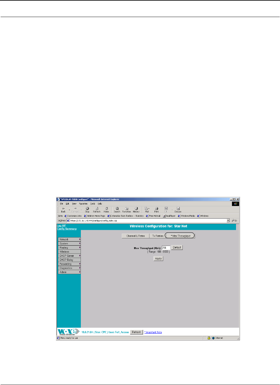
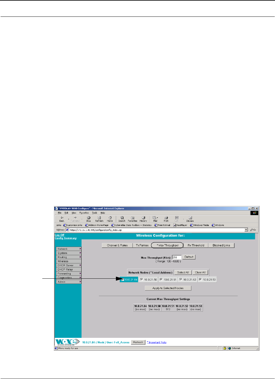
Max Throughput (Regulating Bandwidth)
Max Throughput is useful to ISPs that want to regulate the maximum bandwidth
provided to each customer. The following page appears when the Max Throughput
button is clicked:
Figure 5-6: Max Throughput page
SPEEDLAN 9000 Series Installation and Operation User Guide Version 3.03
Using the Configurator to Set Up Special Parameters for CPE Routers 5-11
The Max Transmit Data Rate (in Kb/s) default is set to 6500. Click Default to get the
default value. The range is from 100 to 6500 Kb/s. Then, click Apply.
Admin Menu
Software Update
Note: The Software Update zip file (found on the Wave Wireless web site under the
Support + Firmware link) will contain a document describing the recent changes and
any other additional information needed to perform the update. The zip file will also
include the update (.wwn) file to perform the update. After you have unzipped the file,
make sure you extract the update file (.wwn) file to your desktop. Then, follow the
directions below.
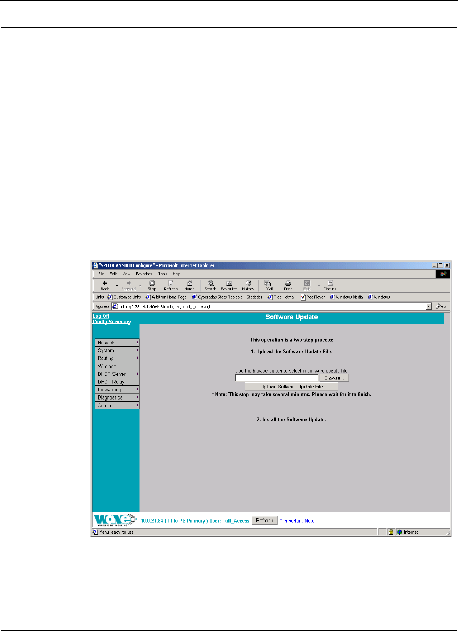
To update the software on a CPE, choose Software Update from the Admin menu.
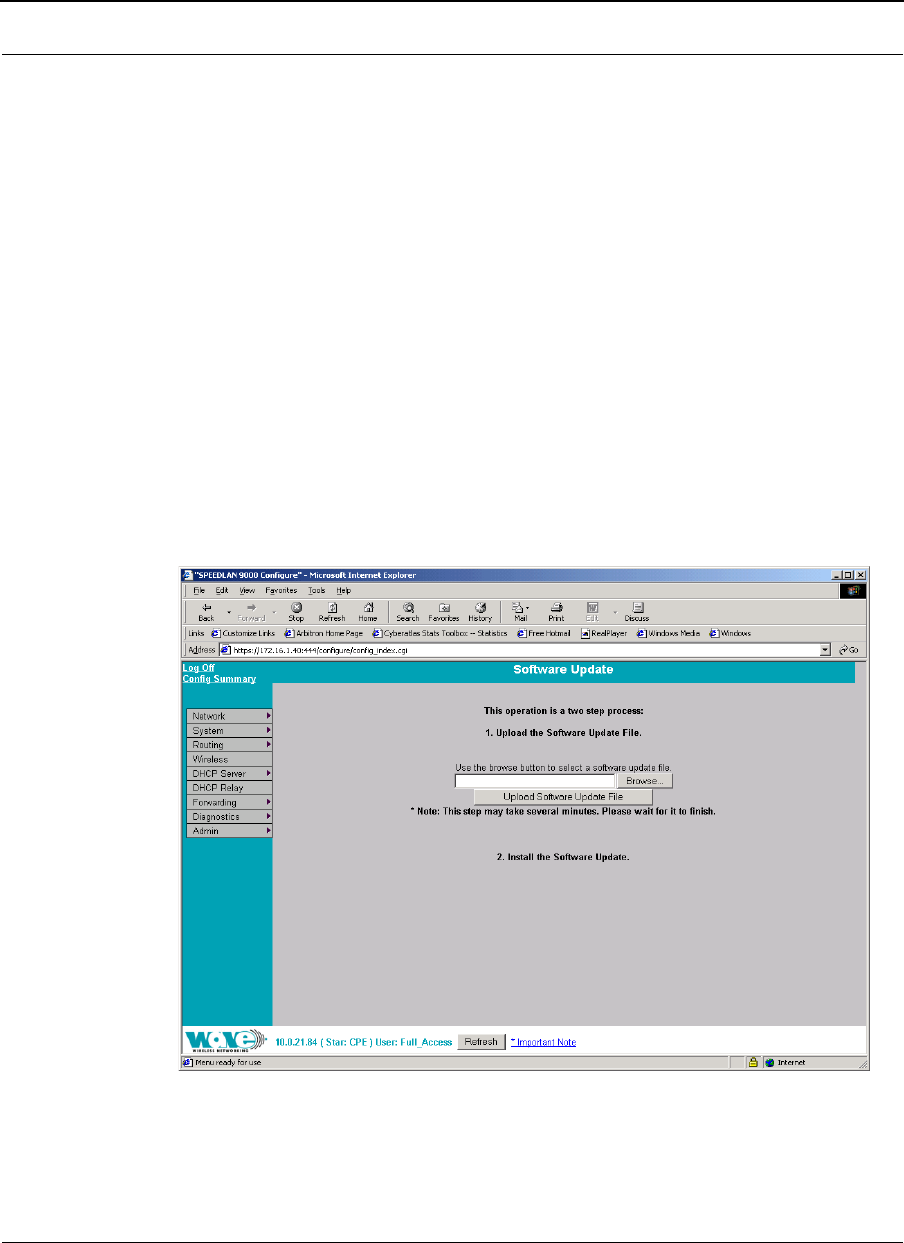
The following page will appear.
Figure 5-7: Updating the software on the CPE
If you obtain a software update file from Wave Wireless Networking, you can use this
page to update software on one or more SPEEDLAN 9000 routers.

Version 3.03 SPEEDLAN 9000 Series Installation and Operation User Guide
5-12 Using the Configurator to Set Up Special Parameters for CPE Routers
This operation is a two-step process:
1Upload the Software Update file. Locate the latest software file (by clicking
Browse) and click Upload Software Update File.
2Install the Software Update.
Note: When you updated your network in the past, the remotes would not have been
rebooted until the final step. This step happened after you clicked the Reboot Updated
Nodes button. Now the remotes are automatically rebooted after a successful
upgrade. The local or connected router is not rebooted until you click the Reboot
Updated Nodes button at the end of the upgrade.

Chapter 6
Using the Configurator to Set
Up Special Parameters for
Point-to-Point Routers
This chapter covers only those special parameters needed to set
up the point-to-point primary and secondary routers, such as:
•Network menu: Interfaces for Point-to-Point Mode,
page 6-2; Point-to-Point Settings, page 6-3; Primary
Station Information, page 6-6; and Authenticating a
Point-to-Point Secondary Router Only, page 6-6
•Wireless: Channel and Rates, page 6-8, Max Tx Retries
and Signaling Rate Fallback, page 6-10 and Max
Throughput (Regulating Bandwidth), page 6-12
•Admin: Remote Control for Point-to-Point Primary
Routers, page 6-13; Software Update for Point-to-Point
Primary or Secondary Routers, page 6-13; and
Updating the Software on a Local Router and Remote
Router: Primary Mode Only, page 6-15
All other common configuration information can be found in
General Functions of the Configurator, page 3-1.
Version 3.03 SPEEDLAN 9000 Series Installation and Operation User Guide
6-2 Using the Configurator to Set Up Special Parameters for Point-to-Point Routers
Network Menu
Interfaces for Point-to-Point Mode
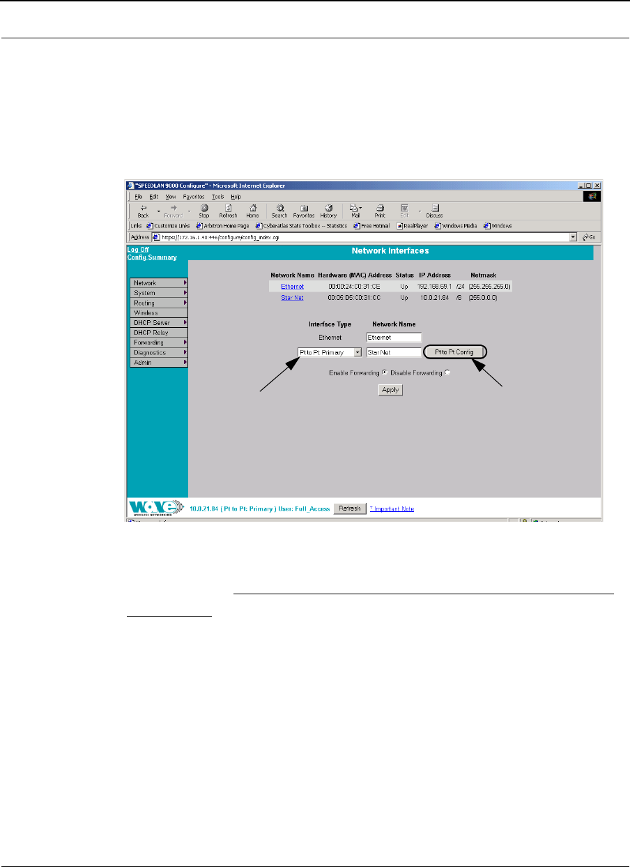
The Network Interfaces page will appear when you choose Interfaces under the
Network menu. This is where you enter the interface type (or router) and network name
of the interface (or the point-to-point primary or secondary router).
Figure 6-1: Selecting point-to-point primary or secondary mode
Important Note: The "Pt to Pt Configure" button is only accessible in point-to-point
primary mode.
•Network Name: This is the fixed or wireless interface (e.g., pt to pt: primary
or pt to pt: secondary).
•Hardware Address: In a LAN environment each network interface contains its
own Medium Access Control (MAC) address which is the embedded and
unique hardware number.
•Status: This is the state of the interface. Up - ready to pass packets; Down -
cannot pass packets.
•IP Address: This address tells the network how to locate the computers or
network equipment connected to it.
Select the point-to-point router
(primary or secondary) from
the Interface Type drop-down
list. When finished, click
Apply. This will tell the config-
urator that you are in point to
point (primary or secondary)
mode.
Click Pt to Pt Configure to
modify authentication or
point-to-point primary or
secondary settings. See If you
clicked the Secondary Node
Settings Button..., page 6-5 for
more information.
SPEEDLAN 9000 Series Installation and Operation User Guide Version 3.03
Using the Configurator to Set Up Special Parameters for Point-to-Point Routers 6-3
•Netmask: The netmask is a 4-byte number that masks the network part of the
Internet Protocol IP address, so only the host computer part of the address
remains.
•Interface Type: Select the point to point router (primary or secondary) from
the Interface Type drop-down list. When finished, click Apply. This will tell the
configurator that you are in point to point (primary or secondary) mode.
•Network Name: The type of network for the wireless or fixed router.
•Enable Forwarding: Select the Enable Forwarding option to enable the
forwarding of IP packets from the wired interface to the wireless interface and
vice-versa.
•Disable Forwarding: Select the Disable Forwarding option to disable the
forwarding of IP packets from the wired interface to the wireless interface and
vice-versa.
•Apply: Click after making changes.
Point-to-Point Settings
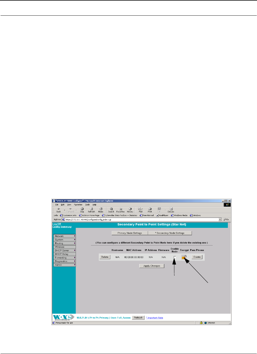
To set up your point-to-point primary or secondary routers (that is, if you are in primary
mode), choose Pt to Pt Config from the Network menu. The following default page
will appear. An alternative is to also click Pt to Pt Config on the Network Interfaces
page.
Figure 6-2: Configuring Secondary Point-to-Point Settings (if in Primary mode)
Select to connect the
router to the network.
If you want to disconnect the
router from the network, do
not select this check box.
Click to
lock or
unlock
encryption.
Version 3.03 SPEEDLAN 9000 Series Installation and Operation User Guide
6-4 Using the Configurator to Set Up Special Parameters for Point-to-Point Routers
For directions on this page (Secondary Point-to-Point Settings), see If you clicked the
Secondary Node Settings Button..., page 6-5.
This page contains two buttons on the top called Primary Node Settings and Secondary
Node Settings:
•Click Primary Node Settings to configure your primary point-to-point router.
For more information, see If you clicked the Primary Node Settings Button...,
page 6-4.
•Click Secondary Node Settings to configure your secondary point-to-point
router. For more information, see If you clicked the Secondary Node Settings
Button..., page 6-5.
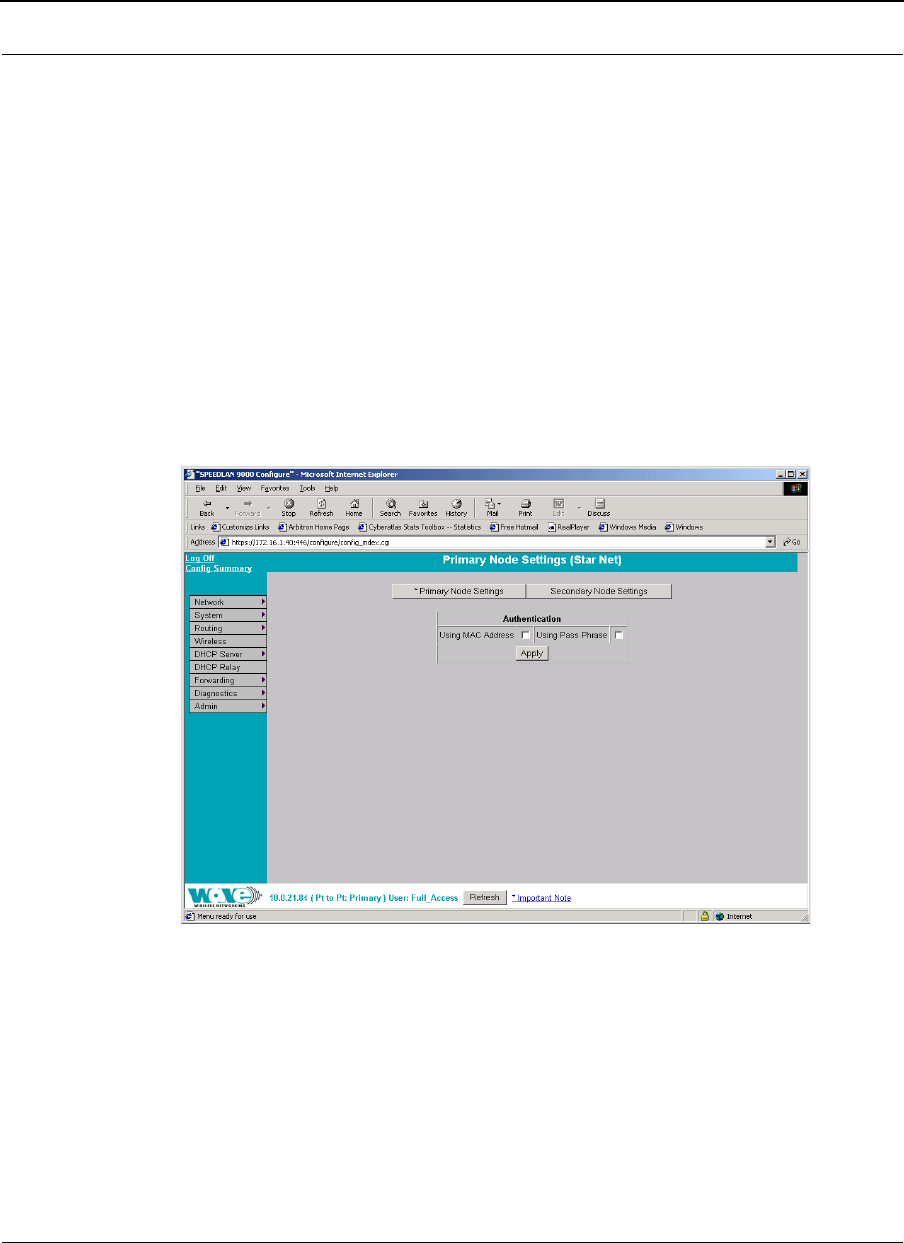
If you clicked the Primary Node Settings Button...
Figure 6-3: Configuring Primary Node Settings (in Primary mode)
Note: The SPEEDLAN 9000 implements an advanced point-to-point mode. The
previous performance tuning parameter (latency vs throughput) was removed from the
Configurator. This means if you used firmware version 2.20 (or an older version), the
tuning parameter appeared for the primary point-to-point node. If you are using
firmware version 2.21 or higher, the tuning parameter will not be displayed. If the

SPEEDLAN 9000 Series Installation and Operation User Guide Version 3.03
Using the Configurator to Set Up Special Parameters for Point-to-Point Routers 6-5
primary node is running firmware version 2.21 or higher, it will automatically optimize
the point-to-point link.
Authentication section
•Using MAC Address: Select this check box if you want to use the factory
default address (MAC layer self learning router mode) for the point-to-point
router. Click Apply to activate selection.
•Using Pass Phrase: Select this check box if you want to use the pass phrase.
The pass phrase for the point-to-point router must match the pass phrase for
the router it is communicating with. Click Apply to activate selection.
If you clicked the Secondary Node Settings Button...
You will also be able to enable encryption for your point-to-point secondary router.
•If you want the router to be connected to the network, click the Enable Node
check box. If you want to disable the router from the network, make sure this
check box is not selected. Encryption is locked if the lock image is displayed,
and encryption is unlocked if the unlocked image is displayed under the
"Encrypt" column.
•Click Modify to change an existing pass phrase. Click Create if the pass
phrase has not been set.
Note: You can configure a point-to-point (primary or secondary) router on this page if
you delete the existing one by clicking Delete.
•Click Apply Changes after making changes.

Version 3.03 SPEEDLAN 9000 Series Installation and Operation User Guide
6-6 Using the Configurator to Set Up Special Parameters for Point-to-Point Routers
Primary Station Information
To see if a secondary point-to-point router is connected to the primary point-to-point
router, choose Primary Station Info from the Network menu. The following page will
appear.
Note: If there is no connection to the primary point-to-point router, a message will
appear confirming that the secondary point-to-point router is not connected to the
primary point-to-point router.
Figure 6-4: Primary Station Information page
Authenticating a Point-to-Point Secondary Router Only
If you are only in point-to-point secondary mode only, you can authenticate the router
on this page.
Note: All interfaces connected to the 9000 router are restricted to systems based on
the authentic pass phrase (or password). Any interface that does not have the correct
pass phrase will not be able to establish a data connection.
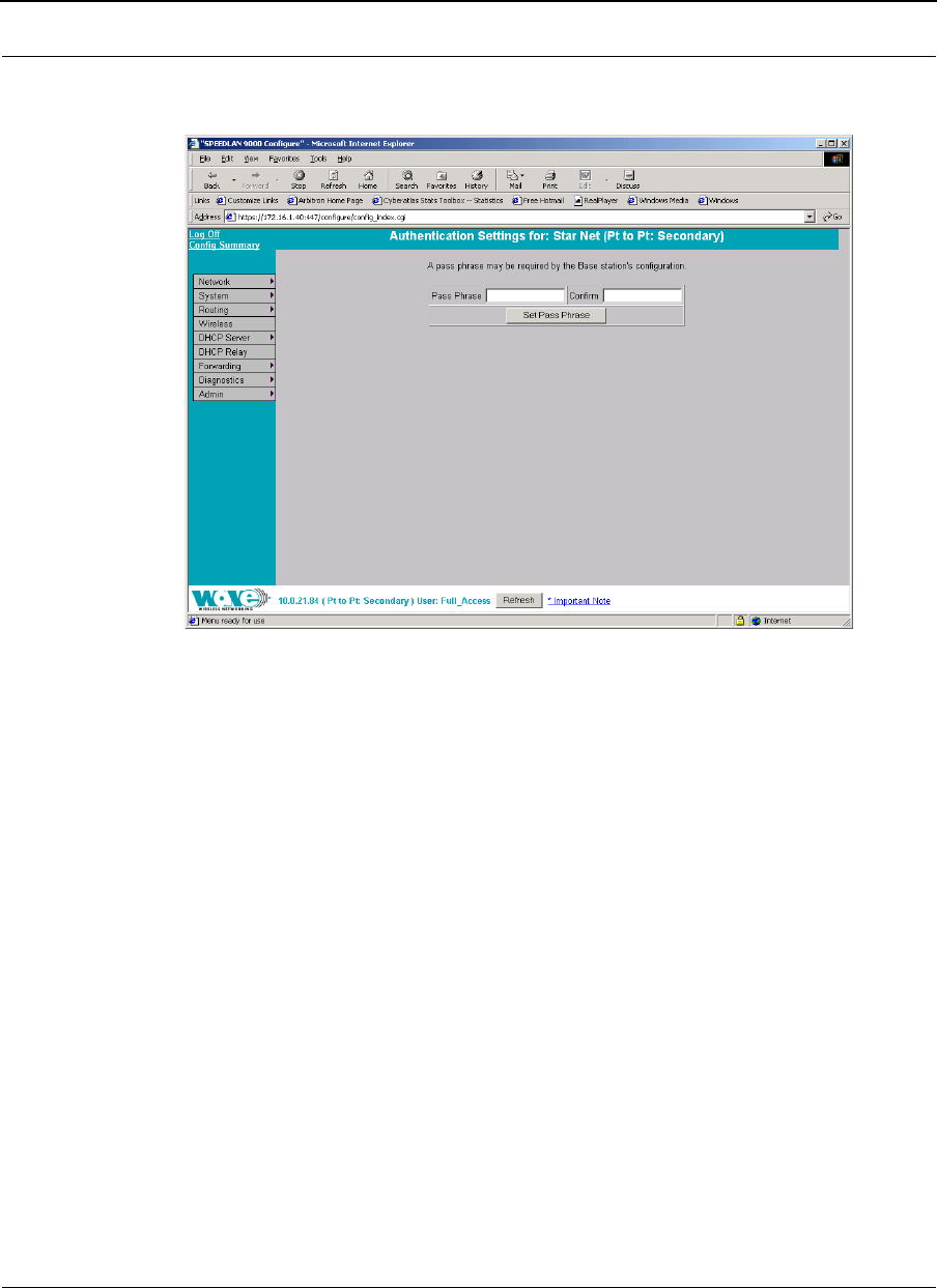
SPEEDLAN 9000 Series Installation and Operation User Guide Version 3.03
Using the Configurator to Set Up Special Parameters for Point-to-Point Routers 6-7
To authenticate a point-to-point secondary router only, choose Authentication from
the Network menu. The following page will appear.
Figure 6-5: Authentication Settings for Point-to-Point Secondary Router page
(while in Secondary mode)
•Pass Phrase: Enter a pass phrase and confirm it like setting up a regular
password. (Pass Phrases have a minimum of 8 characters and a maximum of
32 characters.)
•Confirm: Enter the pass phrase again to ensure it is correct. Make sure you
keep the pass phrase in a safe place.
Wireless menu
Configuration for Point-to-Point
Choose Configuration from the Wireless menu, and click one of the following
buttons:
•If you click the Channel and Rates button, you will be able to select the
channel and signaling rate of the interface. For more information, see
Channel and Rates, page 6-8.
Version 3.03 SPEEDLAN 9000 Series Installation and Operation User Guide
6-8 Using the Configurator to Set Up Special Parameters for Point-to-Point Routers
•If you click the Tx Retries button, you will be able to set the Transmit Retry Limit
and Signaling Rate Fallback. For more information, see Max Tx Retries and
Signaling Rate Fallback, page 6-10.
•If you click the Max Throughput button, you will be able to set the Max
Transmit Data Rate in Kb/s. For more information, see Max Throughput
(Regulating Bandwidth), page 6-12.
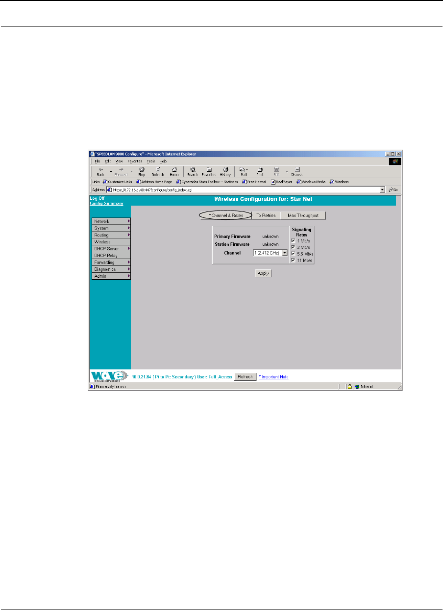
Channel and Rates
Figure 6-6: Channel and Rates (Point primary and secondary)
•Primary Firmware: This is the current primary firmware version in use by the
wireless card.
•Station Firmware: This is the current station firmware version in use by the
wireless card.
•Channel: This is the specific band of frequencies (from 1 to 11) to determine
the data path between routers. All SPEEDLAN 9000 routers expected to
communicate in a network must have the same channel (frequency). Select
one of the following channels (all are represented in GHz) from the Channel
drop-down list:
version: v

SPEEDLAN 9000 Series Installation and Operation User Guide Version 3.03
Using the Configurator to Set Up Special Parameters for Point-to-Point Routers 6-9
12.412
22.417
32.422
42.427
52.432
62.437
72.442
82.447
92.452
10 2.457
11 2.462
•Signaling Rate: This setting refers to the wireless signaling rate. The
SPEEDLAN 9000 routers have four signaling rates that can be used.
Select one of the following check boxes:
•1 Mb/s: This setting limits the card by providing 1 Mb/s of bandwidth.
The minimum receiver sensitivity of the radio with this setting is -92 dBm.
•2 Mb/s: This setting limits the card by providing 2 Mb/s of bandwidth.
The minimum receiver sensitivity of the radio with this setting is -89 dBm.
•5.5 Mb/s: This setting limits the card to providing 5.5 Mb/s of
bandwidth. The minimum receiver sensitivity of the radio with this setting is
-88 dBm.
•11 Mb/s: This is the full 11 Mb/s signaling rate. This value is
recommended for most installations. The minimum receiver sensitivity of
the radio with this setting is -85 dBm.
Note: The network can automatically downgrade the bandwidth if needed (that is, if
lower Mb/s settings are selected). Click Apply when finished.
Version 3.03 SPEEDLAN 9000 Series Installation and Operation User Guide
6-10 Using the Configurator to Set Up Special Parameters for Point-to-Point Routers
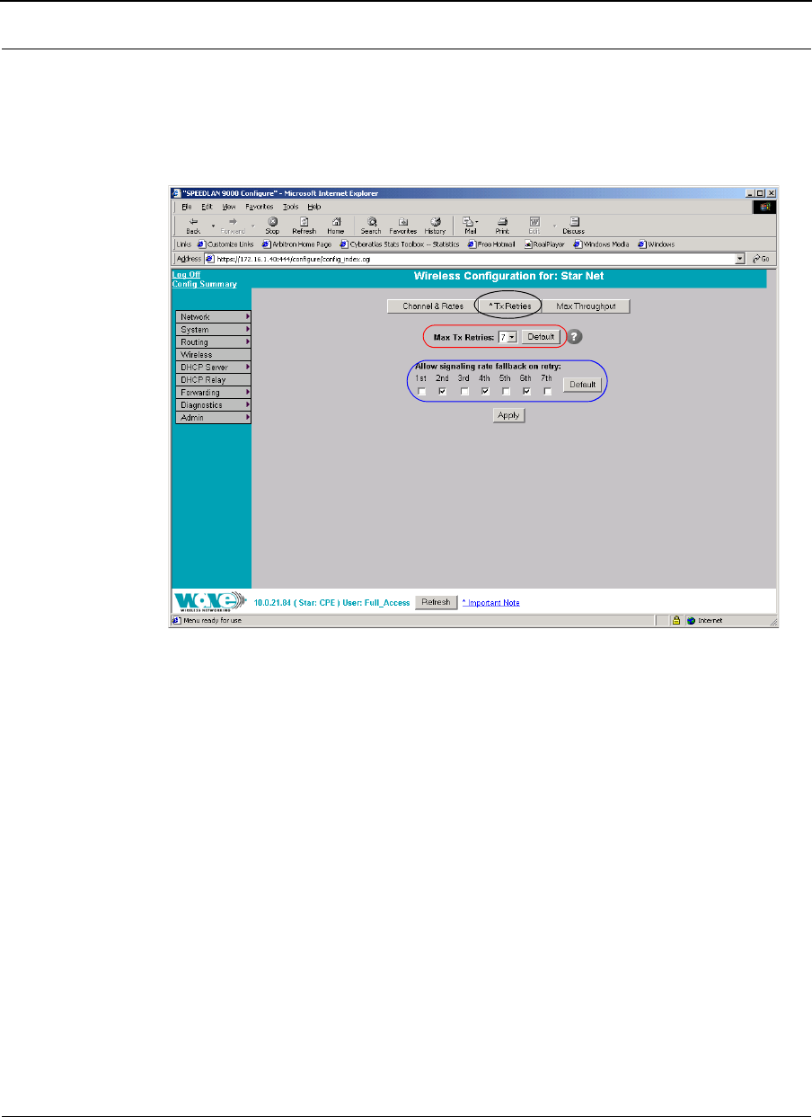
Max Tx Retries and Signaling Rate Fallback
This page includes two features: Max Tx Retries and Signaling Rate Fallback. On the
figure below, Max Tx Retries is circled in red and Signaling Rate Fallback is circled in
blue. The following page appears when the Tx Retries button is selected:
Figure 6-7: Tx Retries and Signaling Rate Fallback (Point primary and secondary)
Max Tx Retries
Wave Wireless recommends that you use this parameter to increase the throughput of
your wireless network. This parameter tells a network node the maximum number of
times a unicast frame can be retransmitted before it is discarded. (A unicast frame is
one that is transmitted to a single node in a network.) This allows a network manager to
tune a network for its particular topology and expected traffic characteristics. The
network topology, RF environment, number of nodes, throughput requirements, latency
requirements, and type of applications are all factors in choosing an appropriate value
for this parameter.
This parameter can be tuned on a per unit basis in order to optimize network
performance. Click Default to get the default value of 7. You can select a value
between 0 and 8 from the Max Tx Retries drop-down list.

SPEEDLAN 9000 Series Installation and Operation User Guide Version 3.03
Using the Configurator to Set Up Special Parameters for Point-to-Point Routers 6-11
Signaling Rate Fallback
During the retransmission of a unicast frame, the signaling rate can "fall back" in order
to increase the chance of reception. Signaling Rate Fallback can occur multiple times
for a single frame. Signaling Rate Fallback occurs from the current rate and will only
include those signaling rates selected on the Channel and Rates page. After ten
consecutive successful unicast frames, the current rate is restored to the highest
selected rate.
The Signaling Rate Fallback parameter allows you to control when the signaling rate
will drop, depending on the check box(es) you selected. That is, the check box(es)
labeled, "Allow signaling rate fallback on retry" (circled in blue on previous figure).
The following parameters (check boxes) govern at which point in the re-transmission
process the rate may be dropped:
•1st retry: Will drop signaling rate on first retry.
•2nd retry: Will drop signaling rate on second retry.
•3rd retry: Will drop signaling rate on third retry.
•4th retry: Will drop signaling rate on forth retry.
•5th retry: Will drop signaling rate on fifth retry.
•6th retry: Will drop signaling rate on sixth retry.
•7th retry: Will drop signaling rate on seventh retry.
Example:
The network administrator has configured the allowable transmit signaling rates to be
11, 5.5, 2, and 1 Mb/s. (These values can be selected on the Channel and Rates page
under the Wireless menu.) In addition, the network administrator has selected 7 from
the Max Tx Retries drop-down list and set the signaling rate to "fall back" on the
second, fourth, and sixth retry attempts (as shown in blue on previous figure). When the
intended recipient does not acknowledge a transmitted unicast frame, it will be
retransmitted again (after a short timeout) at the current rate (e.g., 11 Mb/s). If this
attempt is also unsuccessful (e.g., the receiver did not acknowledge it), the signaling
rate will drop to 5.5 Mb/s and another attempt will be made. If after the third retry, the
transmission is still not successful, the signaling rate will drop to 2 Mb/s for the fourth
and fifth retry, and then to 1 Mb/s for the sixth and seventh retry (if needed).
Version 3.03 SPEEDLAN 9000 Series Installation and Operation User Guide
6-12 Using the Configurator to Set Up Special Parameters for Point-to-Point Routers
The recipient sends acknowledgements at the same signaling rate at which it receives
frames. When a frame is successfully transmitted (acknowledgement received in the
case of unicast), the transmitter immediately proceeds to the next frame. The last
signaling rate used to transmit (other than acknowledgements) becomes the current
rate. After ten consecutive unicast frames, the current rate returns to the highest rate
selected, if it is not already at that signaling rate. Note that the receiver's signaling rate
is not affected (other than returning the acknowledgement at a possibly different rate).
Each transmitter's fallback schedule is independent of the signaling rate used by other
transmitters.
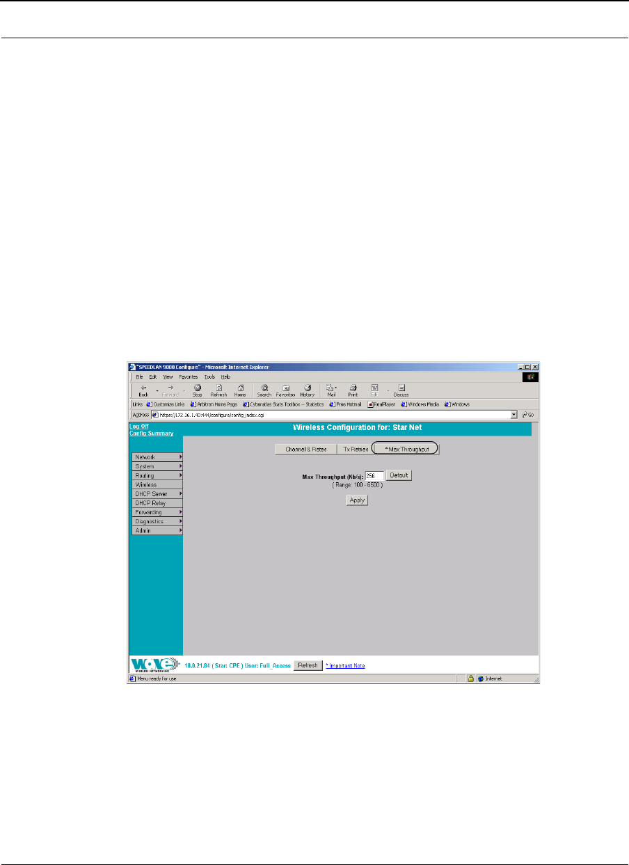
Max Throughput (Regulating Bandwidth)
Max Throughput is useful to ISPs that want to regulate the maximum bandwidth
provided to each customer. The following page appears when the Max Throughput
button is selected:
Figure 6-8: Max Throughput (Point Primary and secondary)
The Max Transmit Data Rate (in Kb/s) default is set to 6500. Click Default to get the
default value. The range is from 100 to 6500 Kb/s.
SPEEDLAN 9000 Series Installation and Operation User Guide Version 3.03
Using the Configurator to Set Up Special Parameters for Point-to-Point Routers 6-13
Admin Menu
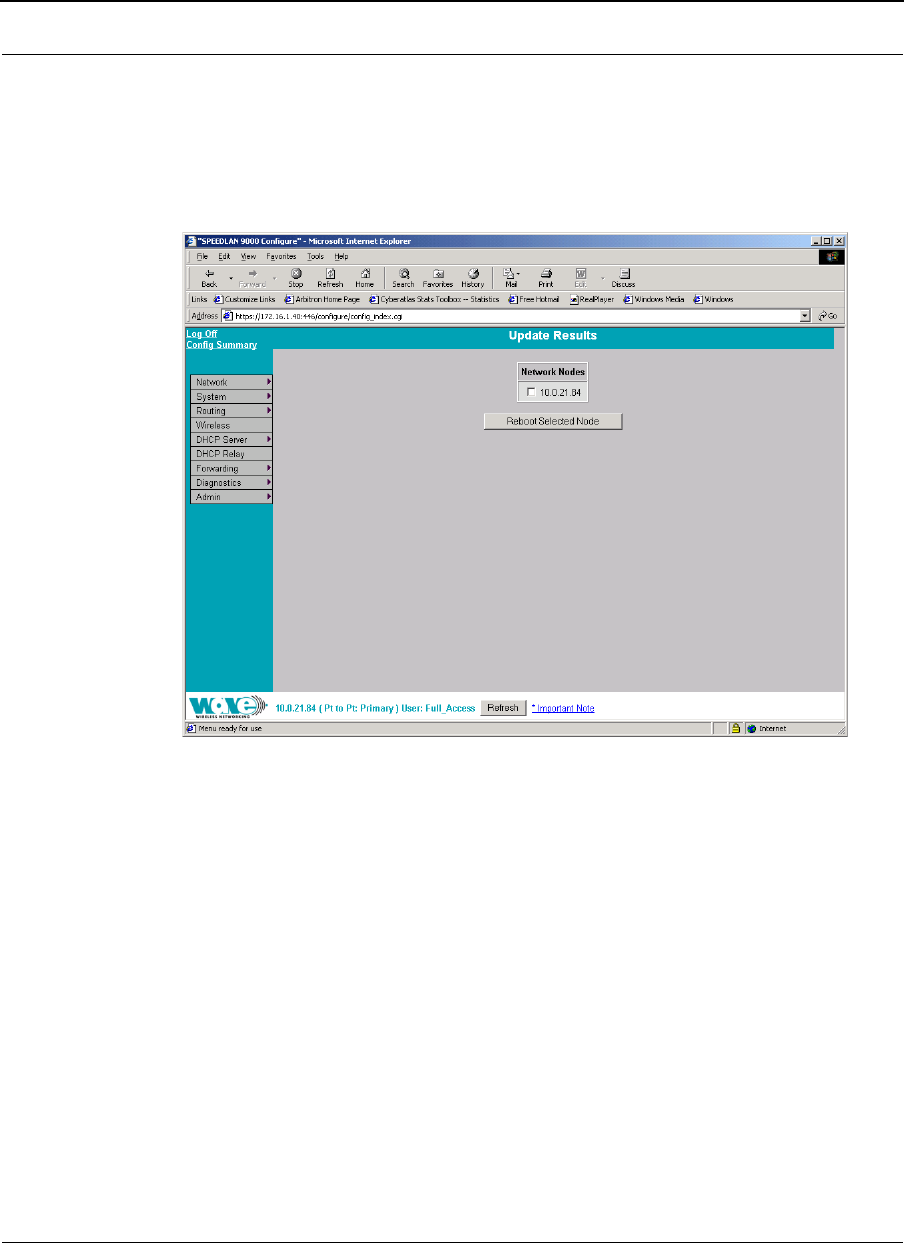
Remote Control for Point-to-Point Primary Routers
To remotely reboot or turn off the SPEEDLAN 9000 point-to-point primary routers,
choose Remote Control from the Admin menu. The following page will appear.
Figure 6-9: Remote Control for point-to-point primary mode (in Primary mode)
Select the primary point-to-point routers you want to reboot and click Reboot Selected
Nodes.
All other common configuration information can be found in General Functions of the
Configurator, page 3-1.
Software Update for Point-to-Point Primary or Secondary
Routers
Note: The Software Update zip file (found on the Wave Wireless web site under the
Support + Firmware link) will contain a document describing the recent changes and
any other additional information needed to perform the update. The zip file will also
include the update (.wwn) file to perform the update.
Version 3.03 SPEEDLAN 9000 Series Installation and Operation User Guide
6-14 Using the Configurator to Set Up Special Parameters for Point-to-Point Routers
After you have unzipped the file, make sure you extract the update file (.wwn) file to
your desktop. Then, follow the directions below.
To update the software on the local router or on the remote point-to-point routers,
choose Software Update from the Admin menu. The Software Update page will
appear.
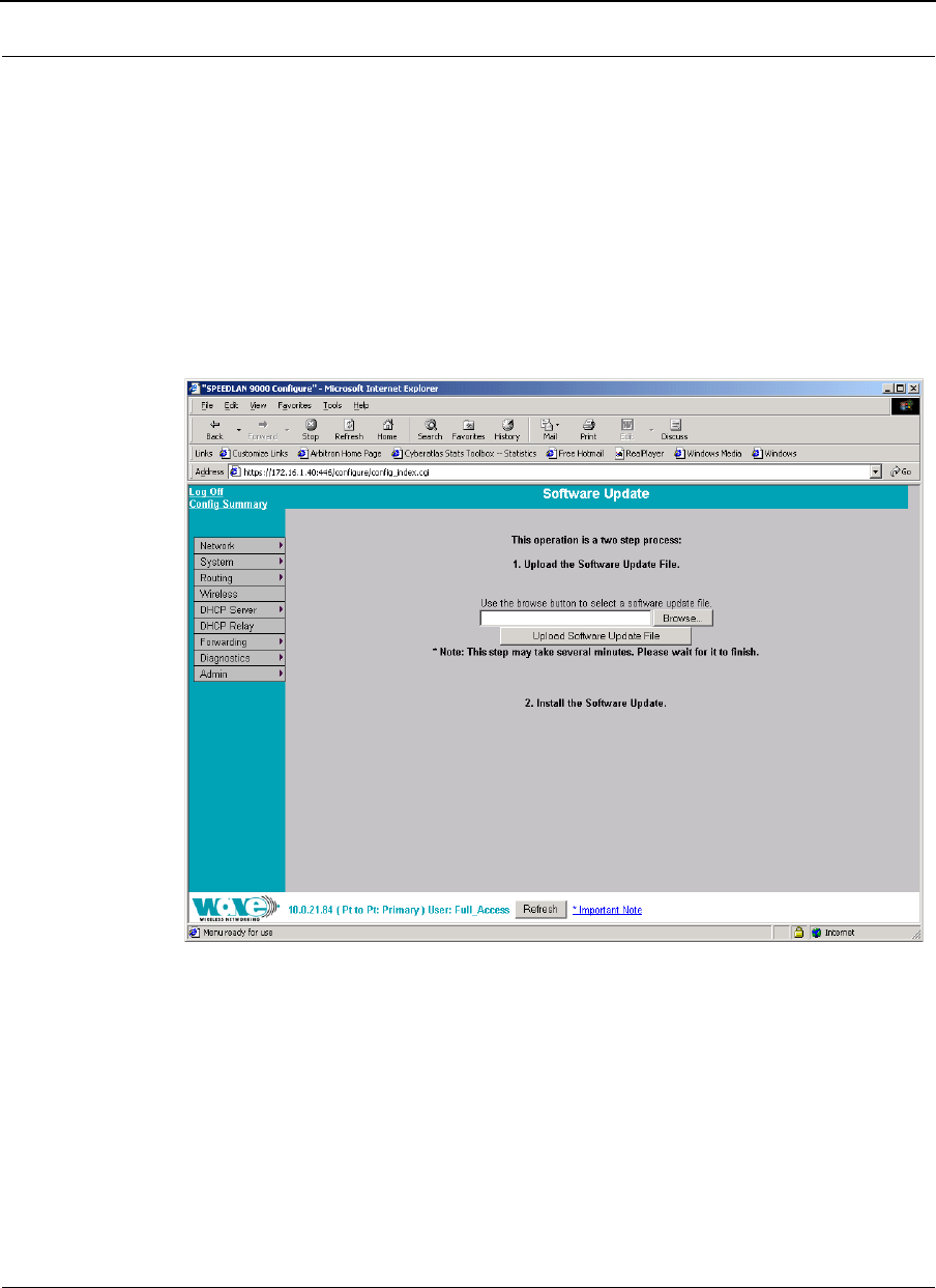
Updating the Local Router
If you only need to update the software on a local point-to-point primary or secondary
router, choose Local (under the Software Update submenu).
Figure 6-10: Updating the software for point-to-point primary or secondary local
router (in Primary or Secondary mode)
This operation is a two-step process:
1Upload the Software Update file. Locate the latest software file (by clicking
Browse) and click Upload Software Update File.
2Install the Software Update. Note: When you updated your network in the
past, the remotes would not have been rebooted until the final step. This step
happened after you clicked the Reboot Updated Nodes button.
SPEEDLAN 9000 Series Installation and Operation User Guide Version 3.03
Using the Configurator to Set Up Special Parameters for Point-to-Point Routers 6-15
Now the remotes are automatically rebooted after a successful upgrade. The
local or connected router is not rebooted until you click the Reboot Updated
Nodes button at the end of the upgrade.
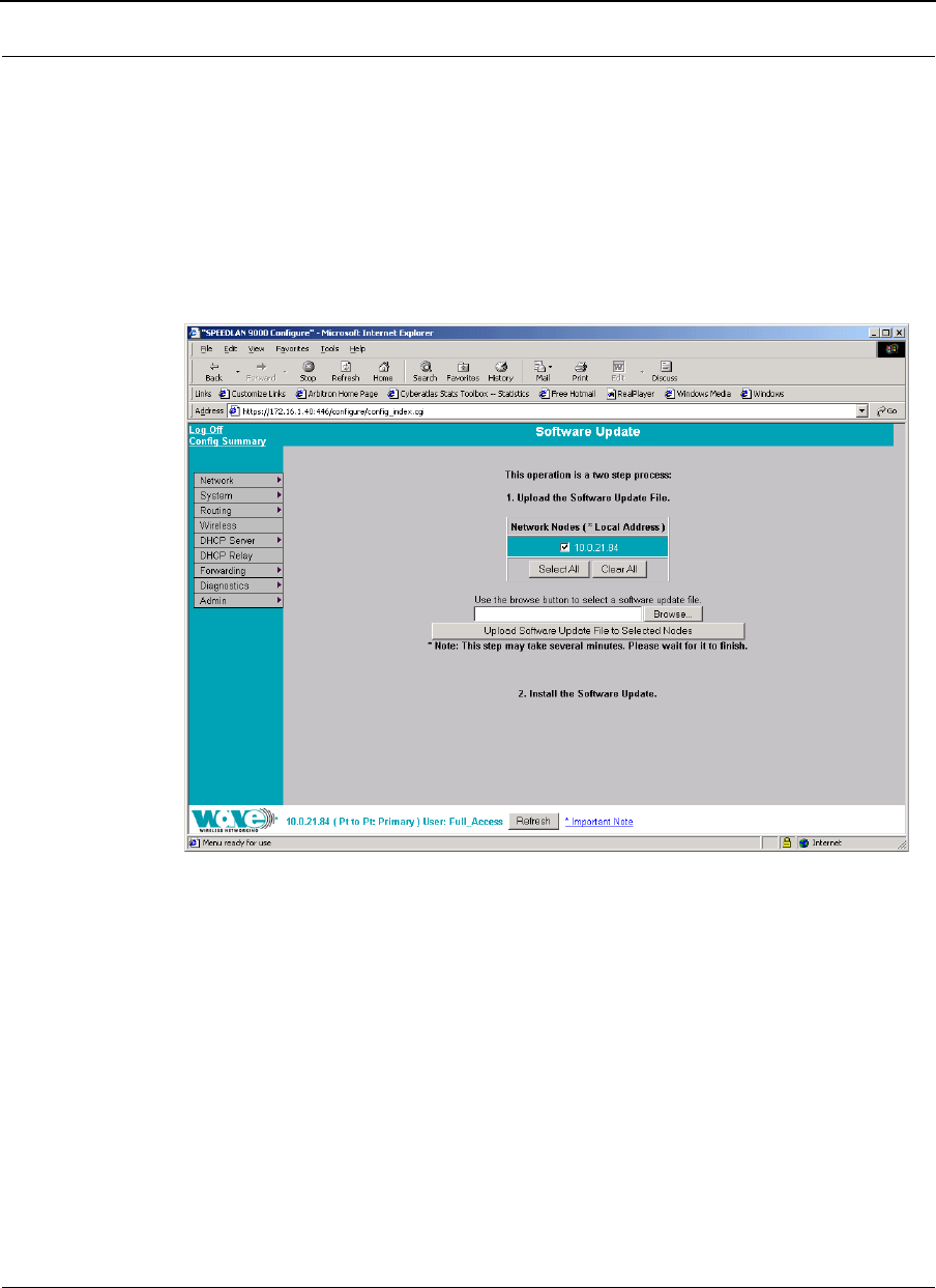
Updating the Software on a Local Router and Remote Router:
Primary Mode Only
To update the software on a location router and on a remote point-to-point primary
router, choose it under the Software Update submenu.
Figure 6-11: Updating the software for a point-to-point primary router (in Primary
mode only)
This operation is a two-step process:
1Select the point-to-point routers where you want to update the software. (The
IP addresses that are selectable are active. If only a MAC address is listed, or a
bunch of zeros, then these represent inactive devices.
2Upload the Software Update file. Locate the latest software file (by clicking
Browse) and click Upload Software Update File to Selected Nodes.
3Install the Software Update. All other common configuration information
can be found in General Functions of the Configurator, page 3-1.

Version 3.03 SPEEDLAN 9000 Series Installation and Operation User Guide
6-16 Using the Configurator to Set Up Special Parameters for Point-to-Point Routers
Notes:_____________________________________________
__________________________________________________
__________________________________________________
__________________________________________________
__________________________________________________
__________________________________________________
__________________________________________________
__________________________________________________
__________________________________________________
__________________________________________________
__________________________________________________
__________________________________________________
__________________________________________________
__________________________________________________
__________________________________________________
__________________________________________________
__________________________________________________
__________________________________________________
__________________________________________________
__________________________________________________
__________________________________________________
__________________________________________________
__________________________________________________

Chapter 7
Using the Configurator to Set
Up Special Parameters for
Mesh Routers
This chapter covers only those special parameters needed to set
up mesh routers, such as:
•Network menu: Interfaces for Mesh Mode, page 7-2;
Mesh Nodes, page 7-3 and Security, page 7-3
•Wireless menu: Configuration, page 7-5
•See also Max Tx Retries and Signaling Rate
Fallback, page 7-8; Max Throughput (Regulating
Bandwidth), page 7-10; Receive (Rx) Threshold
Parameter, page 7-11 and Blocked Links,
page 7-12
•Admin menu: Remote Control, page 7-13; Software
Update, page 7-14; and Updating the Software on a
Local Router and Remote Router, page 7-15
All other configuration information can be found in General
Functions of the Configurator, page 3-1.
Version 3.03 SPEEDLAN 9000 Series Installation and Operation User Guide
7-2 Using the Configurator to Set Up Special Parameters for Mesh Routers
Network Menu
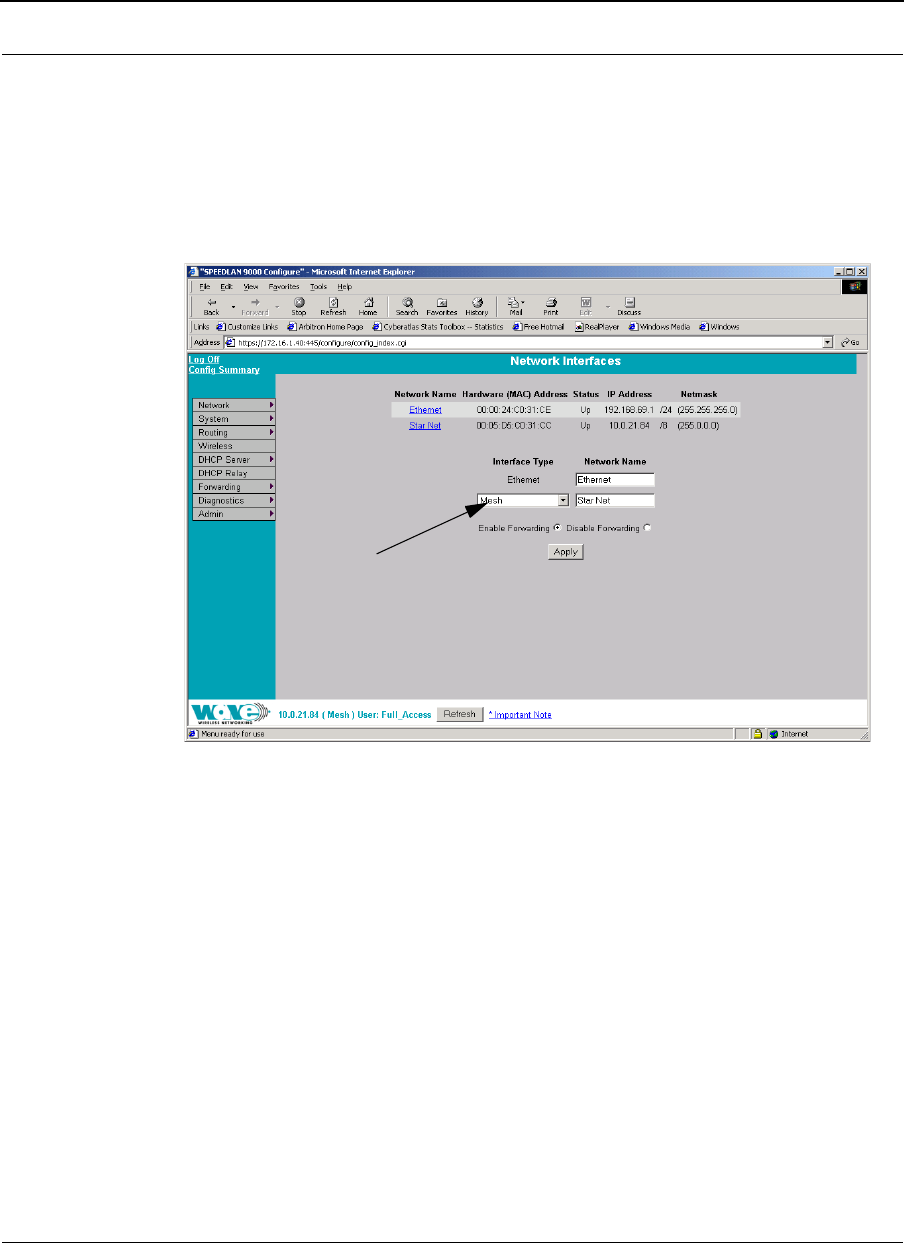
Interfaces for Mesh Mode
The Network Interfaces page will appear when you choose Interfaces under the
Network menu. This is where you enter the interface type and network name of the
mesh interface.
Figure 7-1: Selecting mesh mode
•Network Name: This is the name you assign to the mesh interface.
•Hardware Address: In a LAN environment each network interface contains its
own Medium Access Control (MAC) address which is the embedded and
unique hardware number.
•Status: This is the state of the interface. Up - ready to pass packets; Down -
cannot pass packets.
•IP Address: This address tells the network how to locate the computers or
network equipment connected to it.
•Netmask: The netmask is a 4-byte number that masks the network part of the
Internet Protocol IP address, so only the host computer part of the address
remains.
Select the mesh router from
the Interface Type drop-
down list. When finished, click
Apply. This will tell the config-
urator that you are in mesh
mode.
SPEEDLAN 9000 Series Installation and Operation User Guide Version 3.03
Using the Configurator to Set Up Special Parameters for Mesh Routers 7-3
•Interface Type: Select Mesh from the Interface Type drop-down list. When
finished, click Apply. This will tell the configurator that you are in mesh mode.
•Network Name: The type of network for the wireless or fixed router.
•Enable Forwarding: Select the Enable Forwarding option to enable the
forwarding of IP packets from the wired interface to the wireless interface and
vice-versa.
•Disable Forwarding: Select the Disable Forwarding option to disable the
forwarding of IP packets from the wired interface to the wireless interface and
vice-versa.
•Apply: Click after making changes.
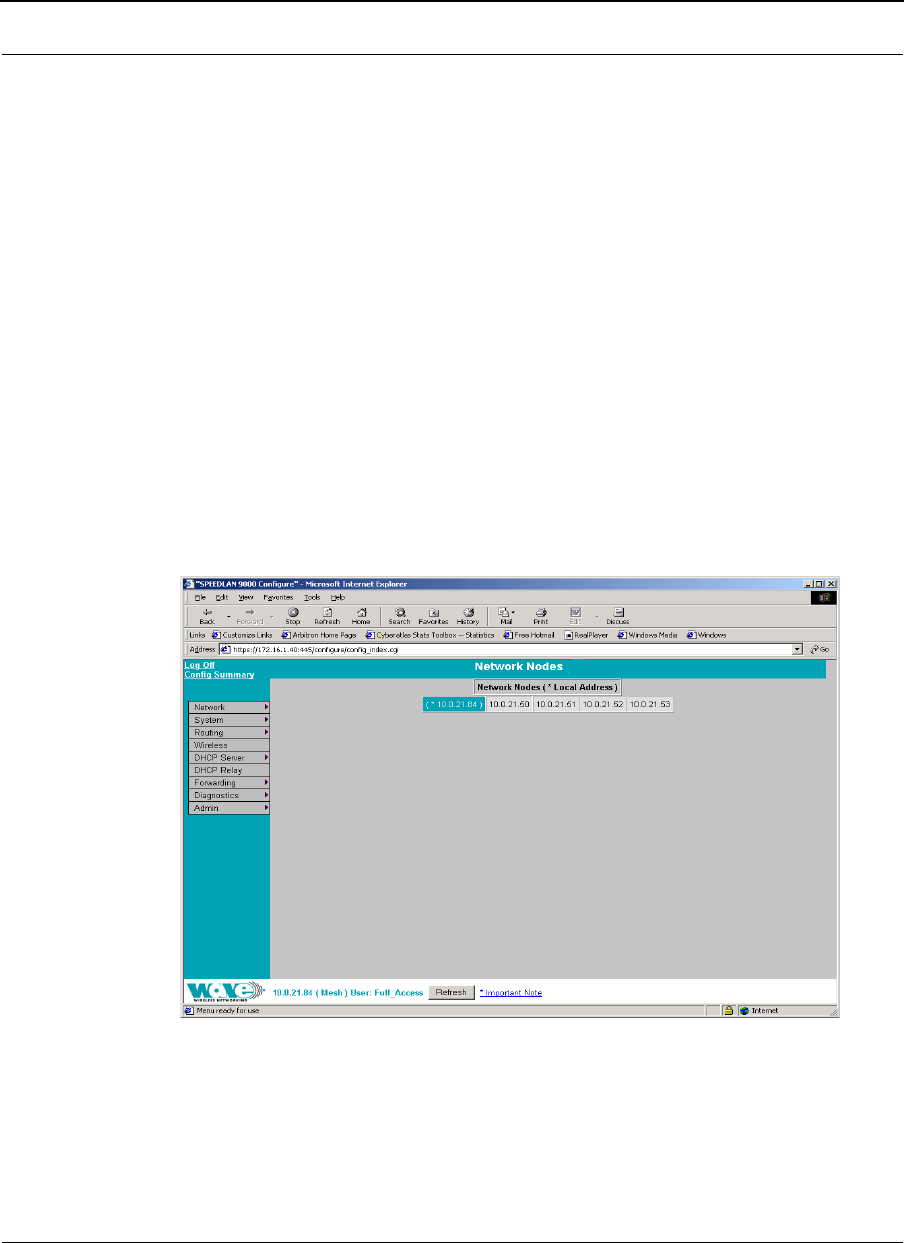
Mesh Nodes
The Mesh Nodes (Network Nodes) page shows you what other routers are currently in
your network. This is useful if you do not have SPEEDView on your workstation. This
page will appear when you choose Mesh Nodes under the Network menu.
Figure 7-2: Network Nodes page
Security
Use this page to set a pass phrase for a mesh router. Just make sure that the password
is kept in a safe place so it is not lost or stolen.
(for Mesh)
Version 3.03 SPEEDLAN 9000 Series Installation and Operation User Guide
7-4 Using the Configurator to Set Up Special Parameters for Mesh Routers
All interfaces connected to the 9000 router are restricted to systems based on the
authentic pass phrase (or password). Any interface that does not have the correct pass
phrase will not be able to establish a data connection.
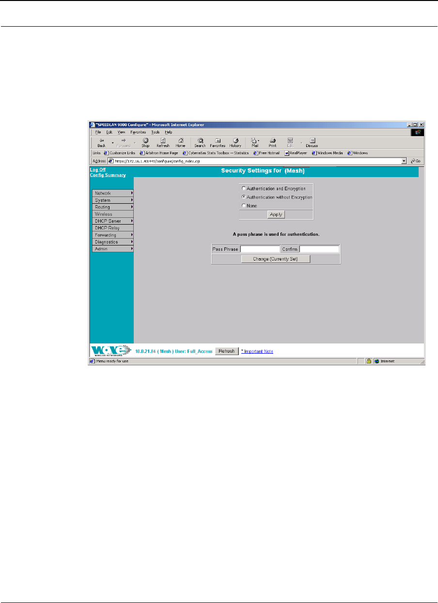
To authenticate a mesh router, choose Security from the Network menu. The
following page will appear.
Figure 7-3: Security Settings page
Use this page to change the security settings for a mesh router. The first section controls
network access for a mesh router. At the lowest level, the mesh routers will only
communicate with each other if they are on the same channel and IP network. There
are two levels of security that can be used to restrict this communication further with
authentication and encryption.
Select one of these options below:
•Authentication and Encryption: the mesh router will only communicate with
other Mesh routers that have the same pass phrase and are encrypting their
traffic.

SPEEDLAN 9000 Series Installation and Operation User Guide Version 3.03
Using the Configurator to Set Up Special Parameters for Mesh Routers 7-5
•Authentication without Encryption: the mesh router will only communicate
with other mesh routers that have the same pass phrase but the traffic will not
be encrypted.
•None: the mesh router will communicate with any other mesh router on the
same channel and IP network without encryption.
A pass phrase is used for authentication in both security modes. Make sure that the
pass phrase is kept in a safe place so it is not lost or stolen.
•Pass Phrase: Enter a pass phrase and confirm it like you would to set a
regular password. (Pass Phrases have a minimum of 8 characters and a
maximum of 32 characters.)
•Confirm: Enter the pass phrase again to ensure it is correct.
If there is no pass phrase set for the system the button will read "Change (Currently Not
Set)". If a pass phrase has been set, the button will read "Change (Currently Set)".
Wireless menu
Configuration
Choose Configuration from the Wireless menu, and click one of the following
buttons:
•If you click the Channel and Rates button, you will see the page shown in the
figure above. For more information, see Channel and Rates, page 7-6 for
more details.
•If you click the Tx Retries button, you will be able to set the Transmit Retry
Limit and Signaling Rate Fallback. For more information, see Max Tx Retries
and Signaling Rate Fallback, page 7-8 for more details.
•If you click the Max Throughput button, you will be able to set the Max
Transmit Data Rate in Kb/s. For more information, see Max Throughput
(Regulating Bandwidth), page 7-10.
•If you click the Rx Threshold button, you will be able to set the threshold for
each mesh router on the network. For more information, see Receive (Rx)
Threshold Parameter, page 7-11 for details.
Version 3.03 SPEEDLAN 9000 Series Installation and Operation User Guide
7-6 Using the Configurator to Set Up Special Parameters for Mesh Routers
•If you click the Blocked Links button, you will be able to block or unblock
mesh routers. For more information, see Blocked Links, page 7-12 for more
details.
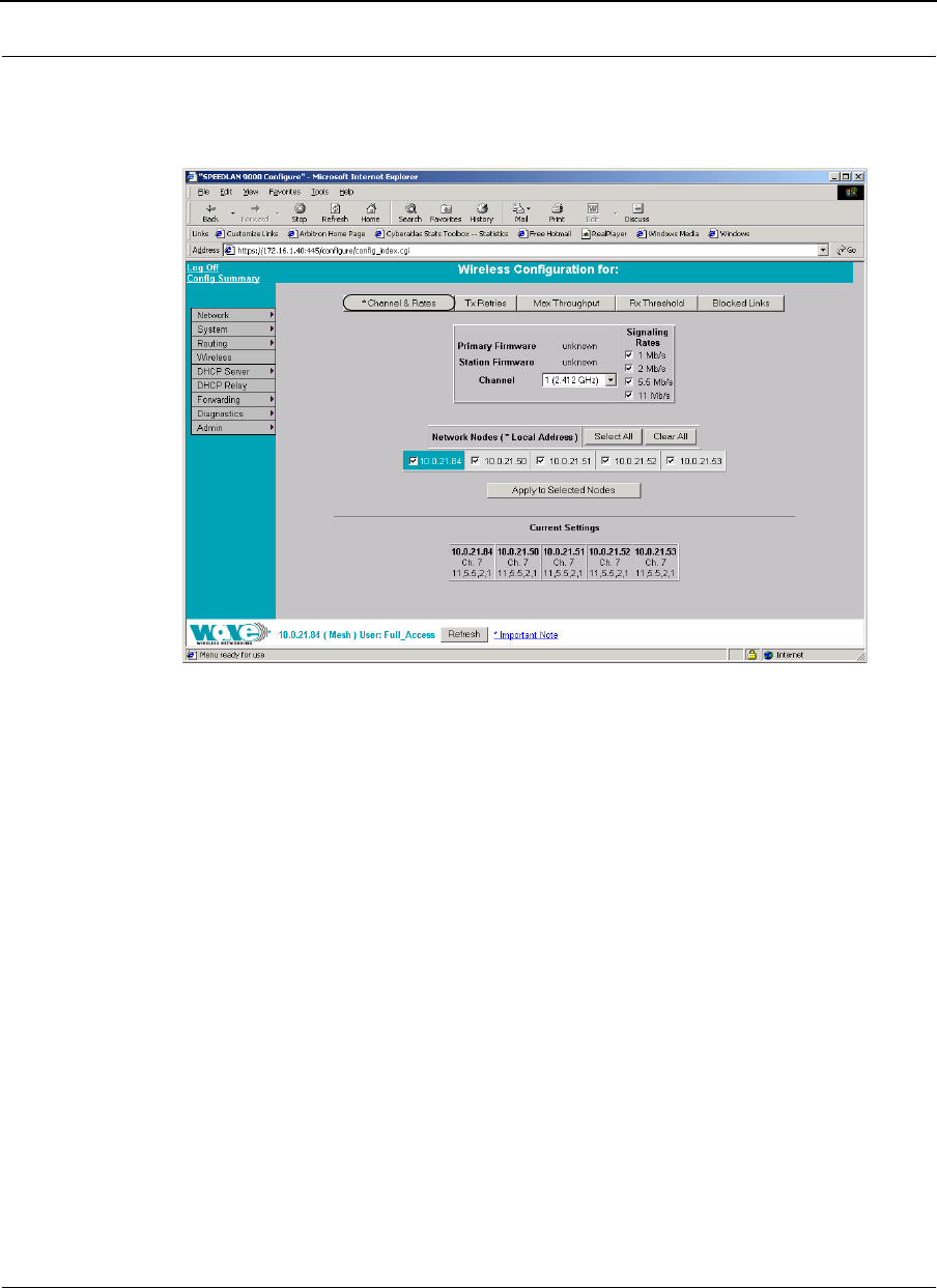
Figure 7-4: Channel and Rates page
Channel and Rates
•Primary Firmware: This is the current primary firmware version in use by the
wireless card.
•Station Firmware: This is the current station firmware version in use by the
wireless card.
•Channel: This is the specific band of frequencies (from 1 to 11) to determine
the data path between routers. All routers expected to communicate in each
pico cell must have the same channel (frequency).
Select one of the following channels (all are represented in GHz) from the
Channel drop-down list:
(Mesh)

SPEEDLAN 9000 Series Installation and Operation User Guide Version 3.03
Using the Configurator to Set Up Special Parameters for Mesh Routers 7-7
12.412
22.417
32.422
42.427
52.432
62.437
72.442
82.447
92.452
10 2.457
11 2.462
•Signaling Rate: This setting refers to the wireless signaling rate. The routers
have four signaling rates that can be used. Select one of the following check
boxes:
•1 Mb/s: This setting limits the card by providing 1 Mb/s of bandwidth.
The minimum receiver sensitivity of the radio with this setting is -92 dBm.
•2 Mb/s: This setting limits the card by providing 2 Mb/s of bandwidth.
The minimum receiver sensitivity of the radio with this setting is -89 dBm.
•5.5 Mb/s: This setting limits the card to providing 5.5 Mb/s of
bandwidth. The minimum receiver sensitivity of the radio with this setting is
-88 dBm.
•11 Mb/s: This is the full 11 Mb/s signaling rate. This value is
recommended for most installations. The minimum receiver sensitivity of
the radio with this setting is -85 dBm.
Note: The network can automatically downgrade the bandwidth if needed (that is, if
lower Mb/s settings are selected).
Note: If you want to use the signaling rate and frequency settings on remote routers,
select them and click Apply to Selected Nodes. If you want to select all of the routers,
click Select All.
Version 3.03 SPEEDLAN 9000 Series Installation and Operation User Guide
7-8 Using the Configurator to Set Up Special Parameters for Mesh Routers
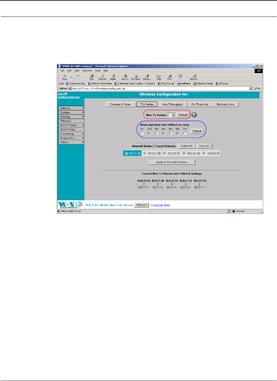
Max Tx Retries and Signaling Rate Fallback
This page includes two features: Max Tx Retries and Signaling Rate Fallback. On the
figure below, Max Tx Retries is circled in red and Signaling Rate Fallback is circled in
blue. The following page appears when the Tx Retries button is selected:
Figure 7-5: Tx Retries and Signaling Rate Fallback page
Note: Click Apply to activate settings.
Max Tx Retries
Wave Wireless recommends that you use this parameter to increase the throughput of
your wireless network. This parameter tells a network node the maximum number of
times a unicast frame can be retransmitted before it is discarded. (A unicast frame is
one that is transmitted to a single node in a network.) This allows a network manager to
tune a network for its particular topology and expected traffic characteristics. The
network topology, RF environment, number of nodes, throughput requirements, latency
requirements, and type of applications are all factors in choosing an appropriate value
for this parameter.
vx.xx
(Mesh)

SPEEDLAN 9000 Series Installation and Operation User Guide Version 3.03
Using the Configurator to Set Up Special Parameters for Mesh Routers 7-9
This parameter can be tuned on a per unit basis in order to optimize network
performance. Click Default to get the default value of 7. You can select a value
between 0 and 8 from the Max Tx Retries drop-down list.
Signaling Rate Fallback
During the retransmission of a unicast frame, the signaling rate can "fall back" in order
to increase the chance of reception. Signaling Rate Fallback can occur multiple times
for a single frame. Signaling Rate Fallback occurs from the current rate and will only
include those signaling rates selected on the Channel and Rates page. After ten
consecutive successful unicast frames, the current rate is restored to the highest
selected rate.
The Signaling Rate Fallback parameter allows you to control when the signaling rate
will drop, depending on the check box(es) you selected. That is, the check box(es)
labeled, "Allow signaling rate fallback on retry" (circled in blue on previous figure).
The following parameters (check boxes) govern at which point in the re-transmission
process the rate may be dropped:
•1st retry: Will drop signaling rate on first retry.
•2nd retry: Will drop signaling rate on second retry.
•3rd retry: Will drop signaling rate on third retry.
•4th retry: Will drop signaling rate on forth retry.
•5th retry: Will drop signaling rate on fifth retry.
•6th retry: Will drop signaling rate on sixth retry.
•7th retry: Will drop signaling rate on seventh retry.
Example:
The network administrator has configured the allowable transmit signaling rates to be
11, 5.5, 2, and 1 Mb/s. (These values can be selected on the Channel and Rates page
under the Wireless menu.) In addition, the network administrator has selected 7 from
the Max Tx Retries drop-down list and set the signaling rate to "fall back" on the
second, fourth, and sixth retry attempts (as shown in blue on previous figure). When the
intended recipient does not acknowledge a transmitted unicast frame, it will be
retransmitted again (after a short timeout) at the current rate (e.g., 11 Mb/s). If this
Version 3.03 SPEEDLAN 9000 Series Installation and Operation User Guide
7-10 Using the Configurator to Set Up Special Parameters for Mesh Routers
attempt is also unsuccessful (e.g., the receiver did not acknowledge it), the signaling
rate will drop to 5.5 Mb/s and another attempt will be made. If after the third retry, the
transmission is still not successful, the signaling rate will drop to 2 Mb/s for the fourth
and fifth retry, and then to 1 Mb/s for the sixth and seventh retry (if needed).
The recipient sends acknowledgements at the same signaling rate at which it receives
frames. When a frame is successfully transmitted (acknowledgement received in the
case of unicast), the transmitter immediately proceeds to the next frame. The last
signaling rate used to transmit (other than acknowledgements) becomes the current
rate. After ten consecutive unicast frames, the current rate returns to the highest rate
selected, if it is not already at that signaling rate. Note that the receiver's signaling rate
is not affected (other than returning the acknowledgement at a possibly different rate).
Each transmitter's fallback schedule is independent of the signaling rate used by other
transmitters.
Max Throughput (Regulating Bandwidth)
Max Tx Rate is useful to ISPs that want to regulate the maximum bandwidth provided to
each customer. The following page appears when the Max Throughput button is
clicked:
Figure 7-6: Max Throughput page
wireless IP address
(Mesh)
SPEEDLAN 9000 Series Installation and Operation User Guide Version 3.03
Using the Configurator to Set Up Special Parameters for Mesh Routers 7-11
The Max Transmit Data Rate (in Kb/s) default is set to 6500. The range is from 100 to
6500 Kb/s. If you click Default, it will load the current default setting for the
Configurator. Click Apply when finished.
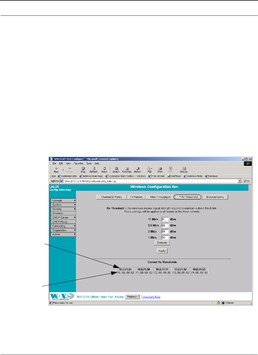
Receive (Rx) Threshold Parameter
From a single mesh unit connected to a mesh network, you can set the receive
threshold (given in dBm), for every mesh router in the network. The receive threshold
specifies the minimum acceptable receive level for a datagram (defined for signaling
rates of 11, 5.5, 2, and 1 Mb/s). Any datagrams received below these levels will be
discarded. This will provide better network stability for networks containing marginal
links, since link state changes (and the corresponding routing changes) will be avoided
for marginal links which are not capable of consistent communication.
By clicking the Defaults button, the values will go to their default values. If you enter a
value of 0 (zero), you are turning the receive threshold parameter off.
Figure 7-7: Rx Threshold page
Note: The default value for the receive signal strength are as follows:
Displays
the wireless
IP address
Displays data
rates
(Mesh)
Version 3.03 SPEEDLAN 9000 Series Installation and Operation User Guide
7-12 Using the Configurator to Set Up Special Parameters for Mesh Routers
•11 Mb/s: 81
• 5.5 Mb/s: 88
•2 Mb/s: 89, and
•1 Mb/s: 92
The current Rx thresholds for your wireless mesh router(s) are listed in the Current Rx
Thresholds section. Their signaling rates are also listed, as described above.
If you click Default, it will load the current default setting for the Configurator. Click
Apply when finished.
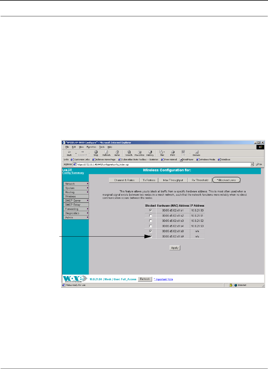
Blocked Links
Figure 7-8: Blocking Mesh Routers
This feature allows you to block all traffic from a specific hardware address. This is most
often used when a marginal signal exists between two nodes in a mesh network, such
that the network functions more reliably when no direct communication occurs between
the nodes. To completely block a link you must perform the same action on the remote
node.
Select the checkbox
under Blocked to block
a mesh router. Leave it
unselected when you
want leave the mesh
router unblocked.
(Mesh)
SPEEDLAN 9000 Series Installation and Operation User Guide Version 3.03
Using the Configurator to Set Up Special Parameters for Mesh Routers 7-13
Note: If you blocked a mesh router, the next time it is rebooted it will remain blocked.
If you want to unblock the router, make sure that the Blocked check box is not
selected.
Note: Click Apply when finished.
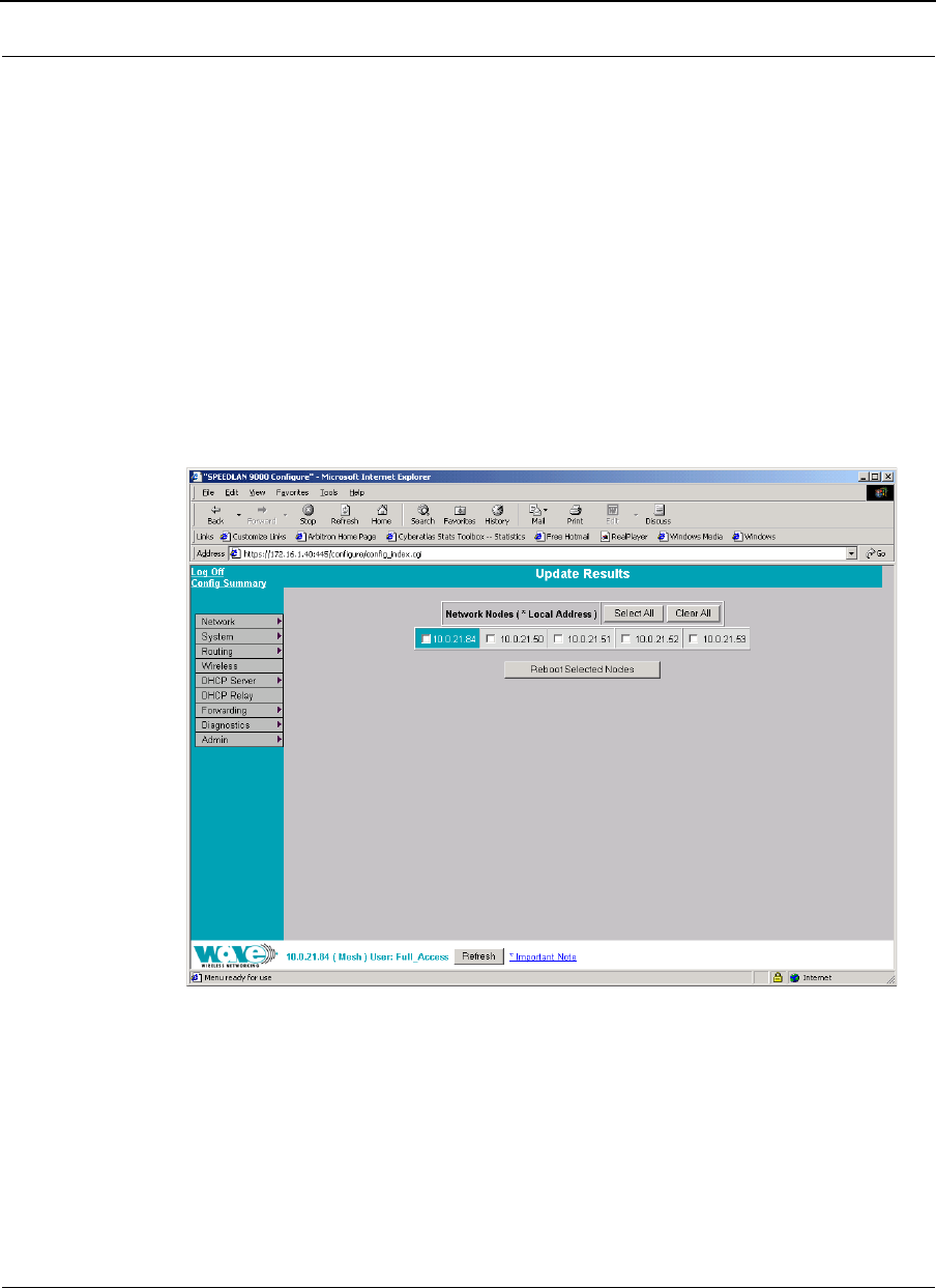
Admin Menu
Remote Control
To remotely reboot or turn off the SPEEDLAN 9000 mesh routers, choose Remote
Control from the Admin menu. The following page will appear.
Figure 7-9: Remote Control for mesh mode
Select the mesh routers you want to reboot and click Reboot Selected Nodes.
Version 3.03 SPEEDLAN 9000 Series Installation and Operation User Guide
7-14 Using the Configurator to Set Up Special Parameters for Mesh Routers
Software Update
Note: The Software Update zip file (found on the Wave Wireless web site under the
Support + Firmware link) will contain a document describing the recent changes and
any other additional information needed to perform the update. The zip file will also
include the update (.wwn) file to perform the update. After you have unzipped the file,
make sure you extract the update file (.wwn) file to your desktop. Then, follow the
directions below.
To update the software on the local router or on the remote mesh routers, choose
Software Update from the Admin menu. The Software Update page will appear.
Updating the Local Router
If you only need to update the software on a local router, choose Local (under the
Software Update submenu).
Figure 7-10: Updating the software for mesh local router
This operation is a two-step process:
Log Off
Config Summary
SPEEDLAN 9000 Series Installation and Operation User Guide Version 3.03
Using the Configurator to Set Up Special Parameters for Mesh Routers 7-15
1Upload the Software Update file. Locate the latest software file (by clicking
Browse) and click Upload Software Update File.
2Install the Software Update.
Note: When you updated your network in the past, the remotes would not be
rebooted until the final step. This step happened after you clicked the Reboot
Updated Nodes button. Now the remotes are automatically rebooted after a
successful upgrade. The local or connected router is not rebooted until you
click the Reboot Updated Nodes button at the end of the upgrade.
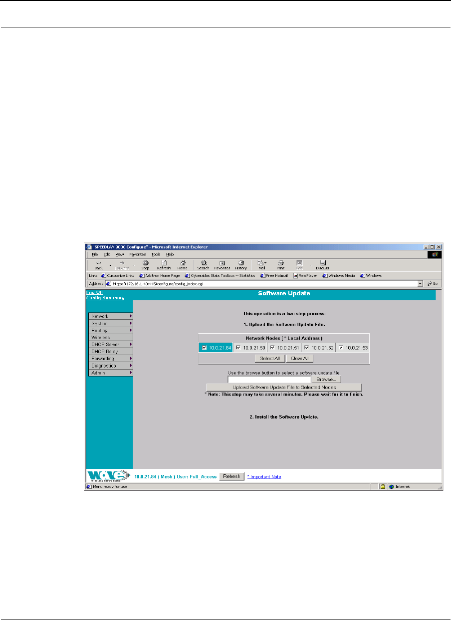
Updating the Software on a Local Router and Remote Router
To update the software on a location router and on a remote router, choose it under
the Software Update submenu (e.g., MeshNet).
Figure 7-11: Updating the software for a local mesh and remote router

Version 3.03 SPEEDLAN 9000 Series Installation and Operation User Guide
7-16 Using the Configurator to Set Up Special Parameters for Mesh Routers
This operation is a two-step process:
1Select the remotes where you want to update the software. (The IP addresses
that are selectable are active. If only a MAC address is listed, or a bunch of
zeros, then these represent inactive devices.
2Upload the Software Update file. Locate the latest software file (by clicking
Browse) and click Upload Software Update File to Selected Nodes.
3Install the Software Update.

Chapter 8
Using SPEEDView
Note: You can configure any 9000 router by either opening the
SPEEDLAN 9000 Configurator or by double-clicking the router
(or node) in the SPEEDView network diagram.

Version 3.03 SPEEDLAN 9000 Series Installation and Operation User Guide
8-2 Using SPEEDView
What is SPEEDView?
SPEEDView® provides an “at-a-glance” view of all the nodes currently on the network.
Network managers can monitor and control management functions for local and
remote SPEEDLAN® 9000 nodes from a central location, or from anywhere on the
network. SPEEDView operates on a Windows platform.
Check your operations quickly with a dynamic graphical user interface, and view the
performance of network links through an easy-to-read graphical format. SPEEDView
uses display lines to indicate direct line-of-sight connections, obstructed connections
(due to network bugs or improper mounting of the antenna) and non-existent physical
connections. These indicators, along with included diagnostic testing features, will help
network managers troubleshoot antenna alignment and locate blocked nodes, so that
paths can be re-routed for successful connectivity. In addition, you can double-click
any node to monitor and update its configuration through the SPEEDLAN 9000
Configurator.
System Requirements
•Runs on the following Windows platforms: 98, ME, NT (Service Pack 4.0),
2000 or XP.
•10 Megabytes of Hard Drive Disk Space
•CD-ROM Drive (for installation)
•Monitor (monochrome is sufficient but VGA or better is highly recommended)
•SPEEDView is compatible with the SPEEDLAN 9000 series
Installation Instructions
Note: You will need to make sure that you have enabled the TCP/IP protocol for your
Ethernet device before using this program.
If you install SPEEDView from the SPEEDLAN 9000 Series CD, follow these
directions:
1Insert the SPEEDLAN 9000 Series CD into your CD-ROM drive.
SPEEDLAN 9000 Series Installation and Operation User Guide Version 3.03
Using SPEEDView 8-3
2 Locate the zip file under the \SPEEDLAN 9000_Files\9000 Management
Software\SPEEDView_& IP Recovery & SPEEDSignal Install_Files directory.
Follow steps 1 through 5 below:
If you are installing an executable from a zip file (e.g., from our website):
Note: SPEEDView can also be downloaded from the Wave Wireless web site "Support"
directory. Locate the link and save the zip file to your desktop.
1Locate the ".zip" file and double-click it. The WinZip® dialog box will appear
on your desktop allowing you to extract the SPEEDView install files. Select the
files and click the Extract button. Next, extract the files to a location on your
computer.
2Click Start on the Windows taskbar. The Start menu appears.
3Choose Run from the Start menu. The Run dialog box appears.
4Locate the executable called setup.exe.
5Follow the installation prompts.
Starting SPEEDView
1When the installation is finished, start the SPEEDView application by doing
one of the following:
•Click the SPEEDView shortcut icon on the desktop, as shown in Figure 8-
1 on page 8-3.
Figure 8-1: SPEEDView shortcut icon
•From the Windows Start menu, choose Programs+
Wave Wireless+SPEEDView. (If SPEEDView was installed in another
folder, select the appropriate directory.)
Version 3.03 SPEEDLAN 9000 Series Installation and Operation User Guide
8-4 Using SPEEDView
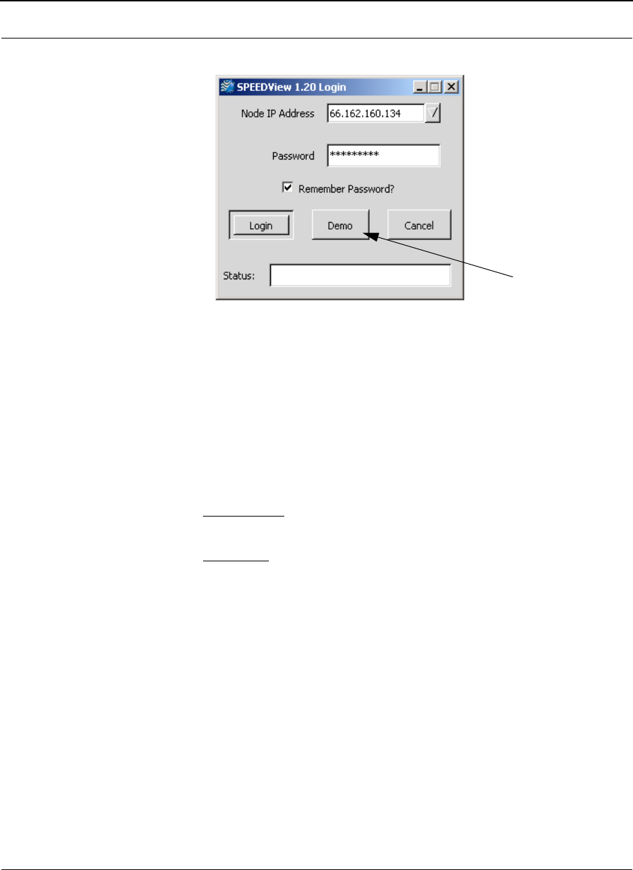
2The SPEEDView Login dialog box appears.
Figure 8-2: SPEEDView Login dialog box
3Enter the IP address (or hostname if you are using a Domain Name Server) of
the 9000 node you want to connect to in the Node IP Address text box. The
last 10 previous IP addresses can be selected in this drop-down box.
4The passwords are defined, based on user class level, in the SPEEDLAN 9000
Configurator. Before you enter the password, decide which account level you
should enter:
•Administrator: allows access to all of SPEEDView’s features (for adminis-
trative use only). The default full access password is “wave_full”.
•Read Only: limits the following features: TCP dump functions, bandwidth
tests, bandwidth toolbar and block and unblock features (items under the
Link menu). The default read-only passwords are “wave_wired" for wired
nodes or "wave_wireless" for wireless nodes.
Note: You can change the password(s) in the SPEEDLAN 9000 Configurator. The
minimum password length is 8 characters. (You can enter 8 characters.) The maximum
password length is 16 characters (including the underscore character or spacebar).
Note: If you want SPEEDView to recall the password for future logins, click Remember
Password. Also, make sure you change the default password for security purposes.
5Click Login.
Note: The Status box (blank text box) at the bottom of the screen displays the status of
the connection.
for previewing
SPEEDView
SPEEDLAN 9000 Series Installation and Operation User Guide Version 3.03
Using SPEEDView 8-5
Note: You can change the default text for the SPEEDView application by clicking
Start+Settings+Control Panel+Display+Appearance tab. Then, select the
appropriate item in the Item list.
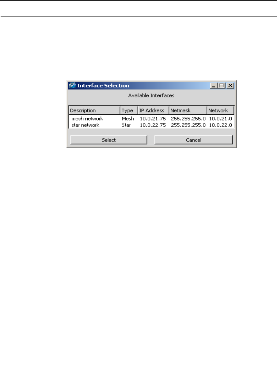
6Next, the Interface Selection box appears which displays all the wireless
interfaces that are connected to the SPEEDLAN 9000 system.
Figure 8-3: (Available) Interfaces Selection box
7Highlight the interface and click Select.
8The following elements are displayed on this box:
•Description: A name for the interface (e.g., where it is located). This can
be changed in the SPEEDLAN 9000 Configurator.
•Type: Star (for base to CPE functionality) or mesh (nodes in a mesh
cloud). The star or mesh network will display on the Main tab, as shown in
Figure 8-4 on page 8-6.
•IP Address: This address tells the network how to locate the computers or
network equipment connected to it.
•Netmask: The netmask is a 4-byte number that masks the network part of
the Internet Protocol IP address, so that only the host computer part of the
IP address remains.
•Network: The address of the network.
Version 3.03 SPEEDLAN 9000 Series Installation and Operation User Guide
8-6 Using SPEEDView
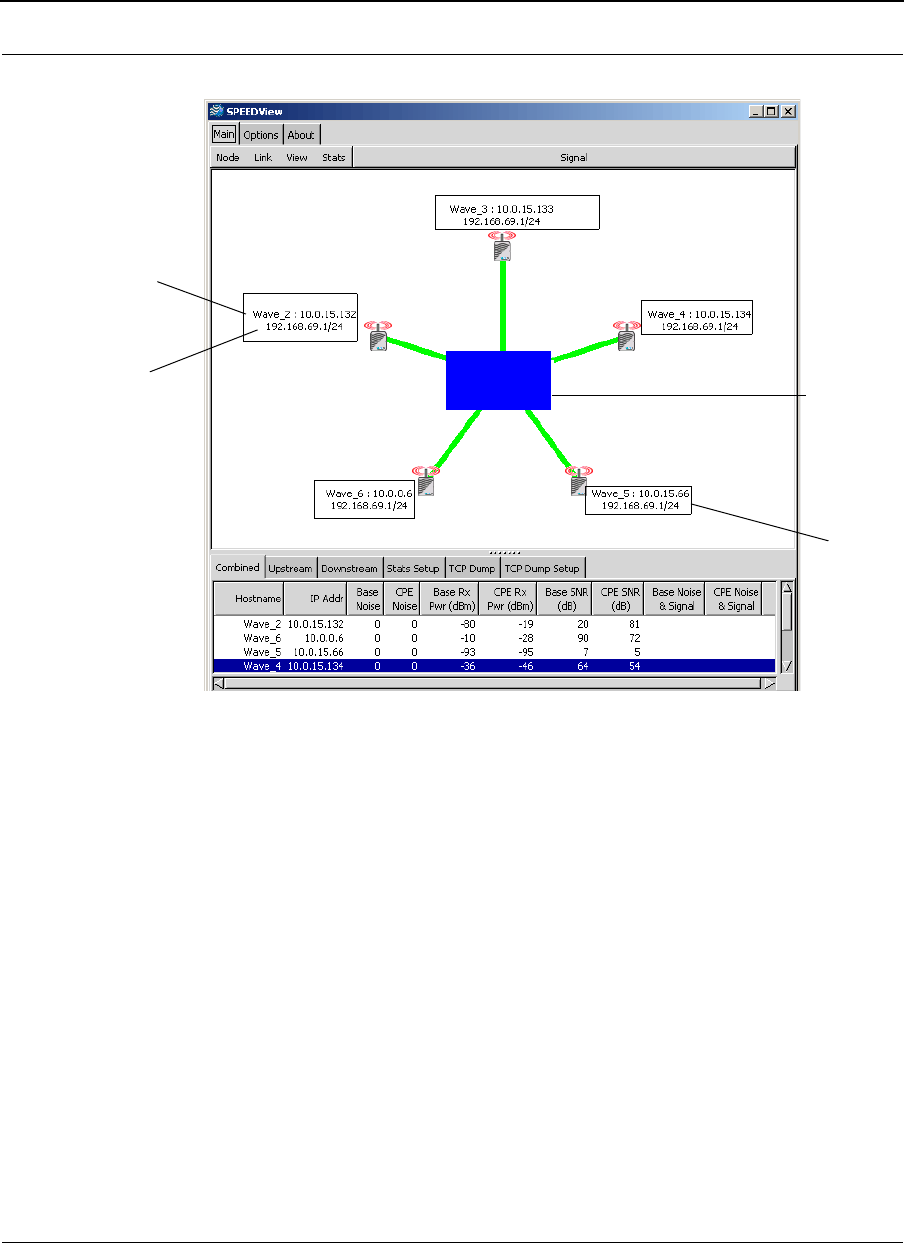
Star Network
Figure 8-4: Star network diagram
Note: A star network consists of a group of remote nodes, called Customer Premise
Equipment (CPE), and a base station. A star network is based on a star topology with
the base station in the center of the star network. Each CPE must have clear line-of-
sight to a base station. (The star node icons are aligned symmetrically.)
You can also use SPEEDView for a point-to-point network. An example can be seen in
the section called SPEEDLAN 9000 Mesh Protocol -- How It Works in Mesh Clouds,
page 1-8.
Wireless Hostname & IP address
Wired hostname & IP address/
netmask
Note: Firmware version
Wave_1: 10.0.15.15
192.168.59.1/24
Version 2.10
Note: This diagram shows the
wireless IP, wired IP, firmware
version and hostname. These
buttons are available on the
Options tab.
1.20
will appear if selected on
Options tab.
base station
Label will
turn red for
its link that
disappears.
SPEEDLAN 9000 Series Installation and Operation User Guide Version 3.03
Using SPEEDView 8-7
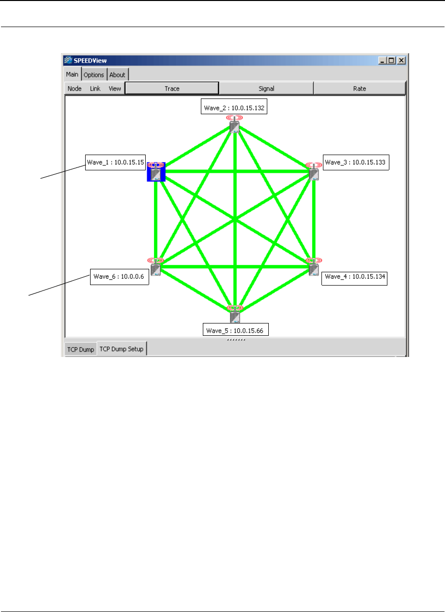
Mesh Network
Figure 8-5: Mesh network diagram
Note: A mesh cloud consists of nodes that have non-line-of-sight functionality,
meaning they are able to route around obstructions by finding the next closest node
within line-of-sight. Mesh nodes reside in a mesh cloud. Each node can communicate
up to a 1/2 mile with its neighboring node. Nodes in the same mesh cloud do not use
a central base station to communicate with each other. Instead, nodes use other nodes
in the mesh cloud to communicate. Mesh clouds can also be linked to other mesh
clouds via gateways and base stations in other LOS networks to improve scalability.
Note: For more information about star and mesh functionality, see SPEEDLAN Polling
Protocol -- How it Works, page 1-6 and SPEEDLAN 9000 Mesh Protocol -- How It Works
in Mesh Clouds, page 1-8.
Note: This
diagram shows
the hostname and
wireless IP address.
This is because
these buttons are
selected on the
Options tab.
1.20
Label will
turn red if
if all links
for that router
disappear.

Version 3.03 SPEEDLAN 9000 Series Installation and Operation User Guide
8-8 Using SPEEDView
The Program Instructions
Note: The Options tab is used for altering the way data is displayed on the Main tab
(e.g., font size, number of octets shown, etc.). The About tab contains version
information about the SPEEDView application. The Options and About tabs are
described in greater detail at the end of this document. For more information, see
Options Tab, page 8-22.
The Main Tab
The elements on the Main tab are discussed in the following order:
•The Main Tab Icons, page 8-9
•The Node, Link, View and Stats Menus (on the Main tab), page 8-11
•Buttons (on the Main tab), page 8-12
•Performing a Bandwidth Test, page 8-14
•Performing a Ping Test, page 8-15
•Accessing the Statistics Tabs on Bottom of Main Tab, page 8-16
SPEEDLAN 9000 Series Installation and Operation User Guide Version 3.03
Using SPEEDView 8-9
The Main Tab Icons
Represents each SPEEDLAN 9000 node. The numerical digit (e.g., “51”) next
to the node represents the last octet(s) of the node’s IP address. This is also
referred to as the IP address or IP label. For more information, see Options
Tab, page 8-22. To view more than one octet or change the font size of the
octet(s), click the Options tab. If you want to display the hostname to the left of
the IP address, click Show Hostname on the Options tab.
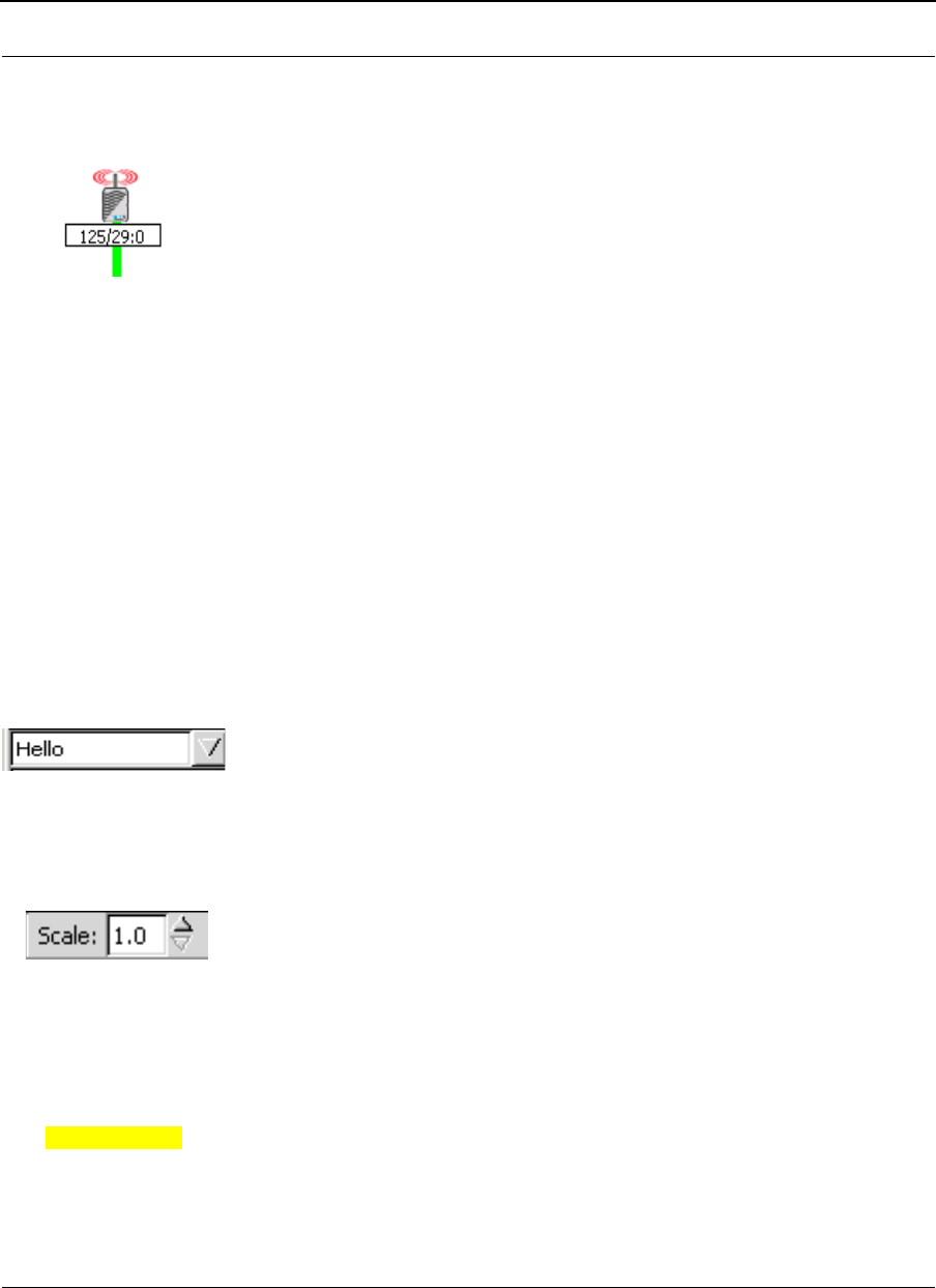
The signal, noise and bit rate for each node pair are indicated inside
square boxes, as shown in the graphic to the left. The higher the signal,
the better. The lower the noise, the better. These values are dynamic and
change constantly to reflect the current state of the network.
To in cl ude the
signal and noise level, click Signal (on the Main tab). To include the bit
rate, click Rate (on the Main tab). To include the noise level, click Show
Noise on the Options tab. To view signal and noise in dBm, click Show
dBm on the Options tab. For more information, see Options Tab,
page 8-22.
Note: The Rate button is only used in mesh mode. The Signal button is
used in both mesh and star modes.
A test message (i.e., Hello, Goodybe, Testing, Marco!, Polo!) can be sent to
any node in the network. The message is automatically echoed by the
receiving node and displayed on your screen to verify end-to-end connectivity
between the nodes. In addition, if another user is currently logged into the
destination node via SPEEDView, he will see your message flash on his the
upper left-hand corner of his network diagram.
The zoom in/zoom out icon is displayed to the right of the test message. Click
the up arrow to zoom in, and click the down arrow to zoom out. If you click
on the network diagram, you can also move it around the desktop.
Black text on yellow indicates that one or more nodes are hidden, and this
message box will be displayed in the lower left-hand corner of the Main tab.
For directions on how to hide a node, see, “Hide” under the The Node, Link,
View and Stats Menus (on the Main tab), page 8-11.
Hidden Node in Trace
Version 3.03 SPEEDLAN 9000 Series Installation and Operation User Guide
8-10 Using SPEEDView
Top picture on left (noted as Fig. A) represents a Trace Route test. Trace Routes
are used for mesh networks only. For directions on how to create a trace route,
see Buttons (on the Main tab), page 8-12.
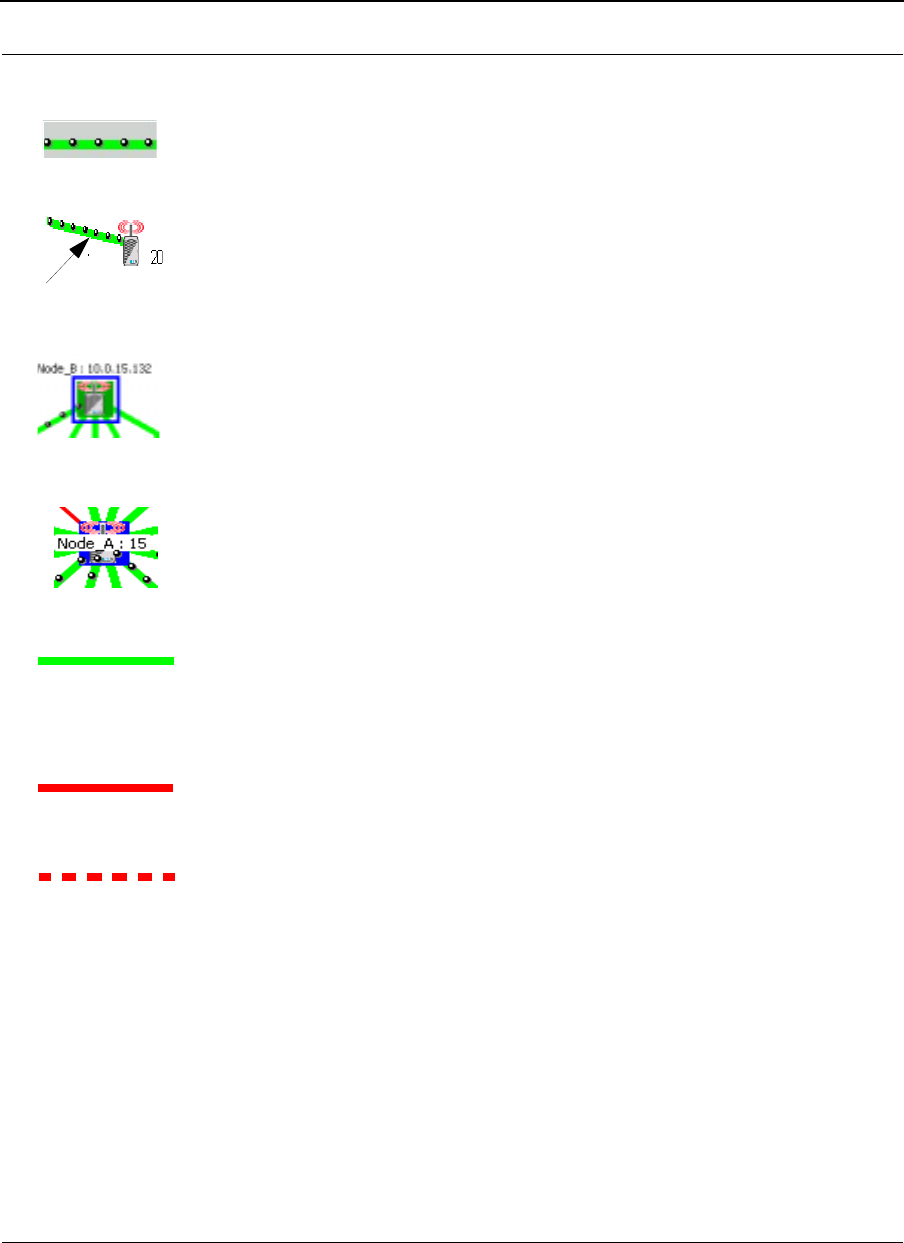
In a star topology, bandwidth on any given link is shown as a series of black
beads, as shown to the left. When the bandwidth beads are closer (as shown
in the bottom picture to the left as Fig. B), this indicates that more bandwidth is
being used. When these beads are further apart, less bandwidth is being used.
Blue, box outlines indicate that the node is selected. Solid green boxes indicate
that the node is the target of a trace route.
Solid, blue squares indicate which 9000 node SPEEDView is connected to. The
IP address of the node will be displayed on top of each node. You can display
the full IP address or part of it by selecting how many octets you want
displayed. For more information, see Options Tab, page 8-22.
Can the nodes hear each other?
Green lines indicate direct line-of-sight connections between SPEEDLAN 9000
nodes.
Solid, red lines indicate that there is not enough signal strength to reliably
exchange data between the node pair, but some signal was detected on at
least one end of the connection.
Dashed, red lines indicate no signal between the node pair.
Red lines are used for debugging and adjusting antennas (e.g., who can hear
and why) in a star network. If a solid, red line appears, the system in a mesh
network could still use an indirect route or hop in order for the two nodes to
exchange data.
A redline without any signal level means that there is no direct communication
between the node pair in a mesh network. Data will automatically be routed
through the 9000 network in order for the node pair to communicate. It is a
user configurable option as to whether a dashed red line, or no line at all,
appears between the node pair without direct communication.
Beads
Bandwidth
Fig.
Fig.
A
B

SPEEDLAN 9000 Series Installation and Operation User Guide Version 3.03
Using SPEEDView 8-11
The Node, Link, View and Stats Menus (on the Main tab)
There are several commands located under the Node, Link, Stats and View menus on
the Main tab.
Figure 8-6: The SPEEDView menu bar
Node menu
•Configure: Choose Configure to launch the SPEEDLAN 9000 Configurator,
which is a web browser used to view/configure many parameters and services
for that node. This is the same as double-clicking any node.
•Hide:
If there are too many nodes to comprehensively view on the 9000
network, select the nodes you want to hide and choose Hide.
•Show: Choose Show to display any nodes that were previously hidden using
the “Hide” feature.
•Select All: If you want to select all of the nodes on the 9000 network (including
hidden), choose Select All. This is useful for hiding a large number of nodes.
Link menu
•Bandwidth Test: Choose Bandwidth Test and a node pair or link to verify that
your equipment is communicating properly at the RF level. This process will
help you during your performance evaluation. See Performing a Bandwidth
Test, page 8-14 for further instructions.
•Ping Test: Choose Ping Test to verify node connectivity. See Performing a Ping
Test, page 8-15 for further instructions.
•Block: (This command is used with mesh networks only.) Select the node pair
or link. (Press the Ctrl key on your keyboard to select more than one node or
link at a time.) Next, choose Block. When you “block” a connection, the node
pair will not be able to communicate.
•Unblock: (This command is used with mesh networks only.) Select the nodes or
links you want to unblock. Next, choose Unblock to clear the “blocked” path.
Version 3.03 SPEEDLAN 9000 Series Installation and Operation User Guide
8-12 Using SPEEDView
View menu
•Message Toolbar: Choose Message Toolbar to display the test message box
just under the Node menu.
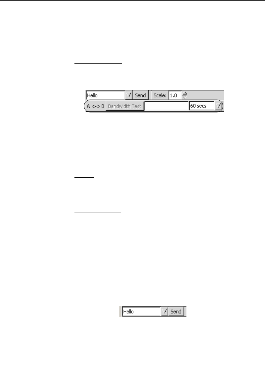
•Bandwidth Toolbar: Choose Bandwidth Toolbar to display a shortcut version
of the bandwidth test (displays results of traffic moving in both directions of the
selected link). Next, you will see the bandwidth toolbar appear on the top of
the Main tab, as circled in Figure 8-7 on page 8-12.
Figure 8-7: Bandwidth Toolbar
Choose the duration: 15, 30 or 60 seconds. Then, click Bandwidth Test. The
results will be displayed in the box to the right of the Bandwidth Test button.
•Zoom: Choose Zoom to zoom in or out.
•Refresh: Choose Refresh to request new hostnames and Ethernet wired IP
addresses.
Stats menu - These are only available for star and point-to-point networks.
•Show All Link Stats: Choose Show All Link Stats to display all the statistics of
all of the links in the statistics window (bottom half of Main tab). For more
information, see Accessing the Statistics Tabs on Bottom of Main Tab,
page 8-16.
•Clear Stats: Choose Clear Stats to remove the statistics of the links in the
statistics window (bottom half of Main tab).
Buttons (on the Main tab)
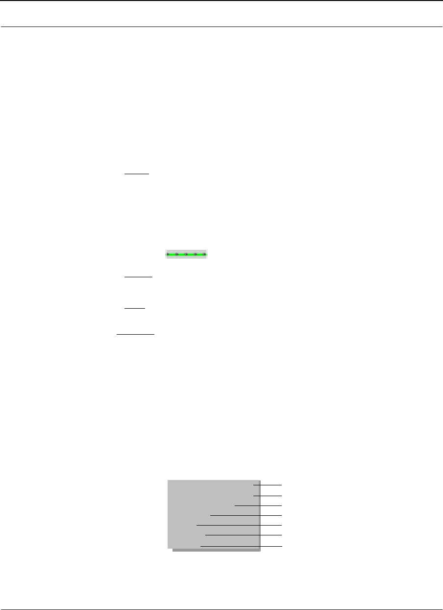
•Send: Click this button to send a UDP-based test message to any node on the
9000 network. Select the test message from the drop-down list such as: Hello,
Goodbye, Testing, Marco or Polo (located just under the Main tab).
Figure 8-8: Send button
results here
SPEEDLAN 9000 Series Installation and Operation User Guide Version 3.03
Using SPEEDView 8-13
Then, select the node where you want to send the test message and click
Send. The remote node automatically echoes the message back to the
originating node.
If successful, you will see your message flash (in blue) on the network diagram.
This indicates a successful round trip of the data.
Note: If someone is monitoring the remote node with another instance of
SPEEDView, he will also see your message appear (in a mesh network).
•Trace: (This button appears for mesh networks only.) Click this button to trace
the data flow between the node pair or link. To set up a trace route, select the
destination node. (The node you are connected to is the source.) Then, choose
Trace. You will see the links chosen by the routing algorithm in order to send
data from the source node to the destination node. The screen shot on the
Main tab with a mesh network (Mesh Network, page 8-7) displays a trace
route --> .
•Signal: Click this button to display the signal strength. Higher values show
stronger received signal strength. The values range from 1-255.
•Rate: Click this button to view the signaling rate (in Mb/s).
Note: Multi-sel: (This button is used for iPAQs only.) All Windows operating systems will
use the standard Ctrl key command to select more than one node.) This button allows
iPAQ users to select more than one node. To deselect nodes, simply click anywhere on
the white screen of the Main tab. Alternatively (and for Windows operating systems),
you can deselect any individual node by clicking on that node. This button is useful
when setting up “blocked” paths (under the Link menu), or “hiding” nodes (under the
Node menu).
Note: If you right-click on the white area in the network diagram, a pop-up submenu
will appear displaying short-cut features depending on the type of network selected.
Figure 8-9: Shortcut pop-up menu
Show All Link Stats
Clear Stats Window
Bandwidth Test
Ping Test
Block
Unblock
Refresh
For star and point to point
For star and point to point
For star, point to point, and mesh
For star, point to point, and mesh
For mesh
For mesh
For all
Version 3.03 SPEEDLAN 9000 Series Installation and Operation User Guide
8-14 Using SPEEDView
These shortcuts are described in the section called The Node, Link, View and Stats
Menus (on the Main tab), page 8-11.
Note: Block and Unblock are used for mesh networks only.
Performing a Bandwidth Test
1Click the node pair or link that you want to test.
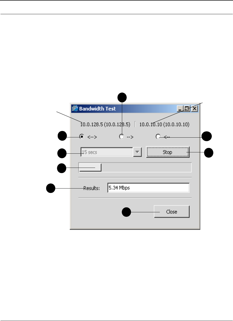
2Choose Bandwidth Test under the Link menu. The Bandwidth Test dialog box
will appear, as shown in Figure 8-10 on page 8-14.
Figure 8-10: Bandwidth Test dialog box
The elements on the Bandwidth Test dialog box are described below:
•a: Tests the full duplex path (e.g., from Node A to B and then from Node B to
A).
•b: Tests the path going to the right (e.g., from Node A to Node B).
•c: Tests the path going to the left (e.g., from Node B to Node A).
•d: The length of time (in seconds) for the bandwidth test.
a
d
f
g
c
e
b
Displays IP address of
left selected node.
Displays IP
address of
right selected
node.
h
SPEEDLAN 9000 Series Installation and Operation User Guide Version 3.03
Using SPEEDView 8-15
•e: Executes the bandwidth test.
•f: Displays results of the bandwidth test (in Mb/s).
•g: Closes the Bandwidth Test dialog box.
•h: Displays the results of the bandwidth test.
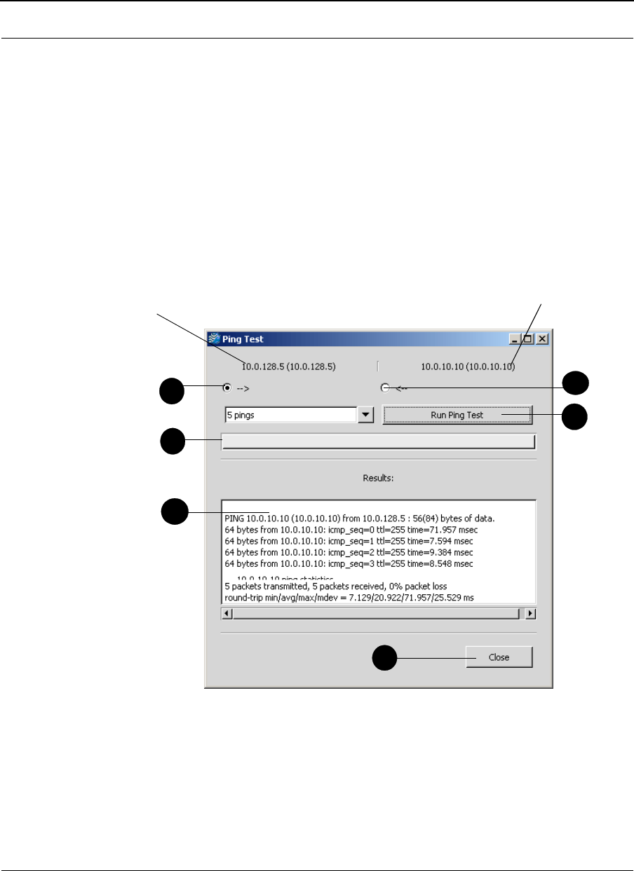
Performing a Ping Test
1Click the node(s) you want to ping.
2Choose Ping Test from the Link menu. The Ping Test dialog box will appear,
as shown in Figure 8-11 on page 8-15.
Figure 8-11: Ping Test dialog box
The elements on the Ping Test dialog box are described below:
•a: Pings the path to the right (e.g., from Node A to Node B).
•b: Pings the path to the left (e.g., from Node B to Node A).
•c: The status bar.
a
d
c
e
f
b
Displays IP address of
selected left node.
Displays IP address of
selected right node.
Version 3.03 SPEEDLAN 9000 Series Installation and Operation User Guide
8-16 Using SPEEDView
•d: Executes the ping test.
•e: Displays the results of the ping test.
•f: Closes the Ping Test dialog box.
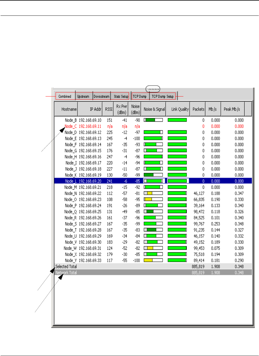
Accessing the Statistics Tabs on Bottom of Main Tab
If you want to enlarge the statistics window, place your mouse on the splitter bar ".......",
as circled (in black) in Figure 8-12 on page 8-16.
Figure 8-12: Statistics window
To tal f or t he
nodes selected
Tot a l nu mbe r of a l l
network activity.
Data turns red
when nodes
are shut down.
Statistics window for the results tested.
in the network
diagram.
Star & Mesh and star & point-to-point
point-to-
point
only

SPEEDLAN 9000 Series Installation and Operation User Guide Version 3.03
Using SPEEDView 8-17
Next, you will see a double arrow pointing up and down, as shown in Figure 8-13 on
page 8-17:
Figure 8-13: Double arrow
Click and push up (to enlarge the window) or down to (decrease the size of the
window). The statistic tabs look similar to the Statistics window shown in Figure 8-12 on
page 8-16.
Note: If you want to remove a link from the Statistics window, right click your mouse in
the window, choose the link row and choose Remove Link (as shown in Figure 8-14
on page 8-17).
Figure 8-14: Remove link shortcut
Downstream Tab
This tab displays information regarding the number of packets moving downstream in
the network. This tab is used only with star and point-to-point networks.
Upstream Tab
This tab displays information regarding the number of packets moving upstream in the
network. This tab is used only with star and point-to-point networks.
Combined Tab
This tab displays information regarding the total number of packets moving
downstream and upstream in the network. This tab is used only with star and point-to-
point networks.
Note: In star networks upstream is from CPE to base station and downstream is from
base station to CPE.
Remove Link
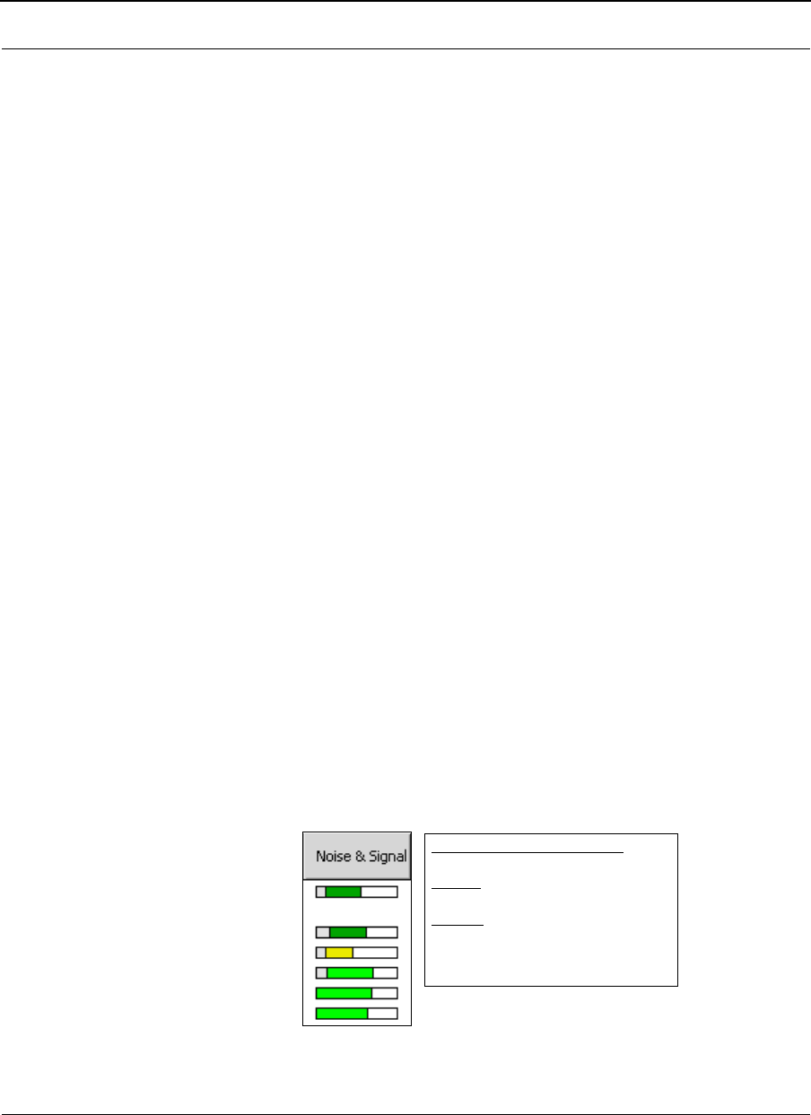
Version 3.03 SPEEDLAN 9000 Series Installation and Operation User Guide
8-18 Using SPEEDView
Stats Setup Tab
This tab allows you to set up the statistics that display on the Downstream, Upstream
and Combined tabs. This tab is used only with star and point-to-point networks. Select
the boxes next to the statistics that you would like to be displayed.
•You can also click Select All (to display all statistics) or None (to select no
statistics).
•Click Zero Counters to temporarily set all packet, byte, polls and missed
counters to zero (0).
•Click Reset Counters to put the counters back to their original values.
The following are statistics you can select to display on the Downstream, Upstream and
Combined sub tabs:
Note: All statistics on this tab are updated every 3 seconds.
•Hostname: The name of the host. Hostnames are set using the SPEEDLAN
9000 Configurator.
•IP Address: This is the IP address of the node.
•Uptime: The amount of time the node has been running.
•RSSI: The Receive Signal Strength Indicator, not measured in dBm.
•Noise: The amount of interference before the packets were received (not
measured in dBm), the lower the better.
•Rx Pwr (dBm): This is the signal strength expressed in dBm.
•Noise (dBm): The noise before the packets were received in dBm.
•SNR (dB): The Signal-to-Noise Ratio, the higher the better.
•Noise & Signal: A combined graphical depiction of signal and noise
percentage.
Figure 8-15: Noise & Signal graphic
Noise & Signal Legend:
Noise: gray color = noise
Signal:
Light green = good activity
Dark green = acceptable activity
Yellow = poor activity

SPEEDLAN 9000 Series Installation and Operation User Guide Version 3.03
Using SPEEDView 8-19
•Link Quality: The percentage of polls a CPE responds to. The higher the
number, the better. This displays the quality of the link. Light green = good
activity (50% or higher). Dark green = acceptable activity.
Yellow = Poor activity).
•Polls: The number of times the station has been polled.
•Missed (Polls): The number of polls that a base station sent that a CPE did not
respond to. This statistic is also updated every 3 seconds.
•Packets: The number of packets that were received (downstream, upstream or
combined).
•Bytes: The number of bytes that were sent to the interface.
•Kb/s: The current bandwidth (downstream, upstream or combined).
•Peak Kb/s: The highest rate of data transfer reached (downstream, upstream
or combined).
•Mb/s: The current bandwidth (downstream, upstream or combined).
•Peak Mb/s: The highest rate of data transfer reached (downstream, upstream
or combined).
•Protocols: (UDP, TCP, ICMP, HTTP, POP3, SMTP, TELNET, FTP, FTP_DATA and
SSH).
Notes:
•Statistics related to mesh networks on this tab are the following: hostname,
Mb/s, IP address, Peak Mb/s, RSSI, Rx Pwr (dBm), Kb/s and
Peak Kb/s.
•Statistics related to star networks on this tab are the following: Hostname,
Noise (dBm), Packets, Protocol-related information, IP address, Bytes, Uptime,
Noise and signal, Kb/s, RSSI, Link quality, Peak Kb/s, Noise, Polls, Mb/s, Rx
Power (dBm), Missed polls and Peak Mb/s.
TCP Dump Tab
This tab allows you to look at packet headers on a given network interface as they
occur. This is useful for determining what traffic a node is receiving when debugging a
network connection. This tab is used with star, point-to-point, and mesh networks.
•Start: Click the node that you want to "TCP dump" and click this button.
•Stop: Stops the TCP dump.
•Clear: Click to clear all information in the output window.
•Show Routes: Click to query the current routing table for the selected node.

Version 3.03 SPEEDLAN 9000 Series Installation and Operation User Guide
8-20 Using SPEEDView
•Show Stats: Click if you want to view the following transmitted and received
wireless statistics for the selected node:
Transmitted Wireless Statistics
•Unicast Frames: Total number of unicast frames transmitted.
•Multicast Frames: Total number of multicast frames transmitted.
•Deferred Transmission: Total number of frames for which one or more
transmission attempt(s) was deferred to avoid a collision.
•Single Retries: Total number of frames successfully transmitted after one
(and only one) retransmission.
•Multiple Retries: Total number of frames successfully transmitted after
more than one retransmission.
•Retry Limit Exceeded: Total number of frames not transmitted
successfully because the retry limit was reached.
•Discards: Total number of frames discarded to free up buffer space.
Received Wireless Statistics
•Unicast Frames: Total number of unicast frames received.
•Multicast Frames: Total number of multicast frames received.
•Star Topology Frames: Total number of star topology frames received.
•Mesh Topology Frames: Total number of mesh topology frames
received.
•Foreign 802.11 Frames: Total number of 802.11 frames received.
•FCS Errors: Total number of frames considered to be destined for this
station, but received with an FCS error.
•Overruns: Total number of frames discarded to free up buffer space.
•Save to File: Click to save all text in the output window for diagnostic
purposes.
TCP Dump Setup
This tab allows you to set up TCP Dump. This tab is used with star, point-to-point and
mesh networks.
•Use: Select this box to activate the item you want to include.
•Item: The item to filter.
•Src: The filter item only applies to the source of the packet.

SPEEDLAN 9000 Series Installation and Operation User Guide Version 3.03
Using SPEEDView 8-21
•Dest: The filter items only applies to the destination of the packet.
Filter items
•IP Address: Use this to include (exclude) the display of packets destined for or
coming from (or both) to a given network host.
•Port: Use this to include (exclude) the display of packets destined for or
coming from (or both) a given network port. Select port by protocol: HTTP
(80), POP3 (110), SMTP (25), TELNET (23), FTP (21), FTP_Data (20), SSH
(22) or Custom (the port you enter).
•Protocol: Select either ARP (Address Resolution Protocol), IP (Internet
Protocol), TCP (Transmission Control Protocol), and UDP (User Datagram
Protocol)
•Interface: The wired (i.e., eth1) or wireless (i.e., wlan1) interface where the
device is connected.
•Include Selected From Above: Click to enter the selected criteria into the
“Include” filter list.
•Exclude Selected From Above: Click to exclude the selected criteria into the
"Exclude" filter list.
•Remove Selected: Highlight the filter criteria you want to remove and click
this button.
•Clear: Click to remove all filter criteria items from this box.
Select the boxes next to the filter item(s) that you would like to define.
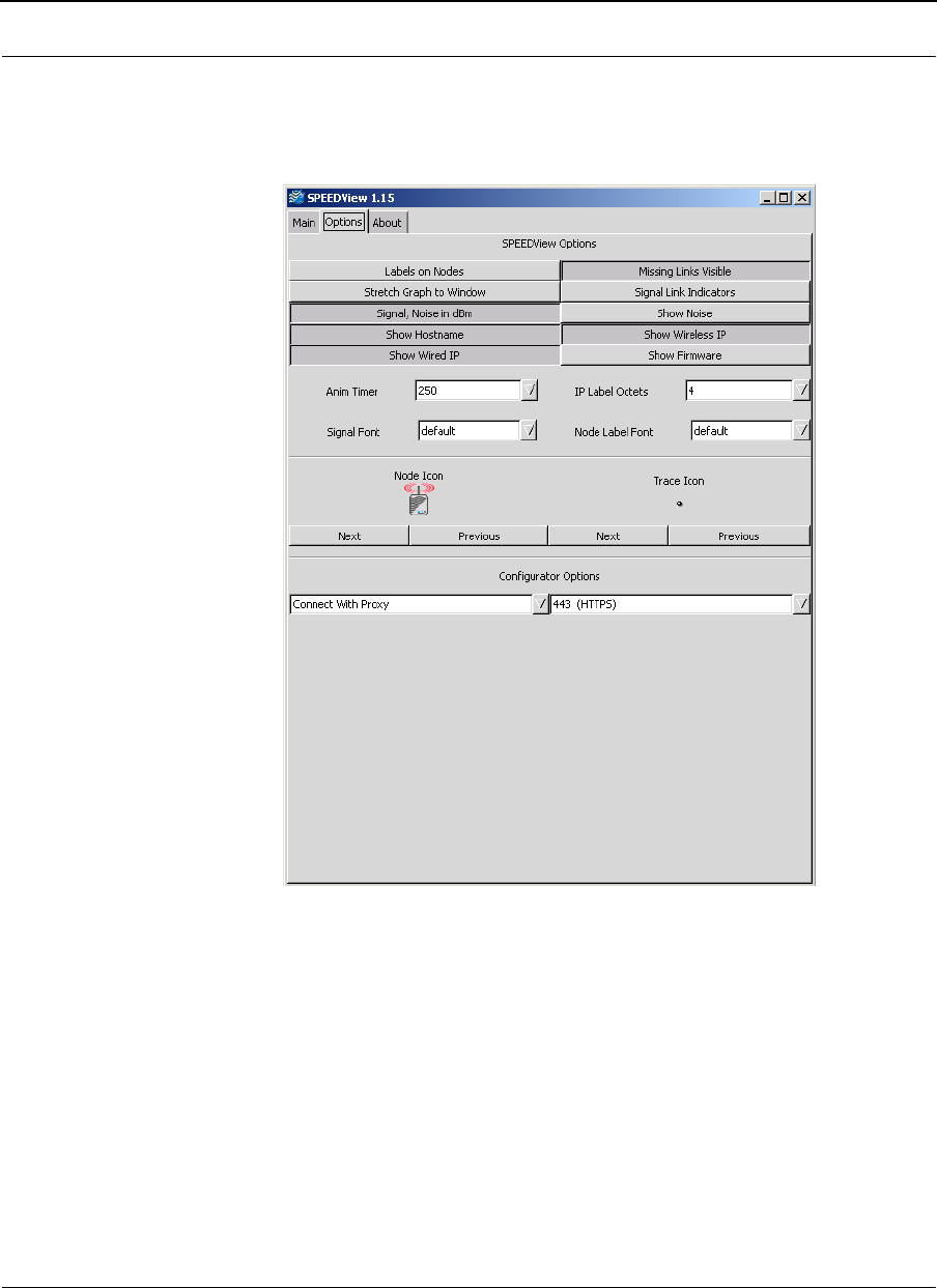
Version 3.03 SPEEDLAN 9000 Series Installation and Operation User Guide
8-22 Using SPEEDView
Options Tab
To customize how the network diagram will appear on the Main tab, click the Options
tab. The following tab will appear.
Figure 8-16: Options tab
Elements on Options Tab:
•Labels on Nodes: Click to display the IP address (IP label) on the node. If this
item is not selected, the IP label will be displayed next to the node.
•Stretch Graph to Window: Click if you want the network diagram to use all
of the available window space.
•Show dBm: Click to show the dBm (decibels per milliwatt). 0 dBm is defined
as 1mw at 1 kHz of frequency at 600 ohms of impedance (displays near node
on Main tab). Note: Signal (on the Main tab) must be selected to show dBm.

SPEEDLAN 9000 Series Installation and Operation User Guide Version 3.03
Using SPEEDView 8-23
•Show Hostname: Click to show the hostname of the wireless node (displays
on node on Main tab).
•Show Wired IP: Click to show the wired IP address and netmask. (The Star
diagram network, as shown in “Star Network” on page 6, shows an example
of this button being enabled. The Mesh diagram, as shown in “Mesh Network”
on page 7, shows an example of this button NOT being enabled.)
•Missing Links Visible: Click to display broken links. The broken (or
disconnected) link will appear as a red, dashed line. This link appears when
there is no signal strength between nodes. If this item is not selected, the link
will be absent between the broken links.
•Signal Link Indicators: Selecting this item will produce graphical link
indications to show which link a Signal label is attached to. This is useful for a
large number of nodes. In order to display the signal, you must have clicked
Signal (on the Main tab).
•Show Noise: Click to display the noise for the wireless node (displays to the
right of the Signal on the Main tab). In order to display the noise, you must
have clicked Signal (on the Main tab).
•Show IP Address: Click to display the wired IP address (displays near node on
Main tab).
•Show Wireless IP: Click to display the wireless IP address (displays near node
on Main tab).
•Show Firmware: Click to display firmware version (displays near node on
Main tab).
•Anim Timer (Animation Timer): Select this drop-down list to change the
animation speed during a trace route test. The speed is measured in
milliseconds.
•Signal Font: To change the font size of the signal, click this drop-down list
and select one of the following: default, tiny, small, medium or large.
•IP Label Octets: To change how many octets appear for the label (IP address
or IP label) on the Main tab, click this drop-down list. You can select up to 4
octets. (Note that selecting “4” will display the full IP address.)
•Node Label Font: This is the font used to display the IP Label. To change the
size, click this drop-down list and select one of the following: default, tiny,
small, medium or large.
•Node Icon: This displays how the SPEEDLAN 9000 node will appear on the
Main tab. You can select one of the following: Smiley Face, Node,
SPEEDView icon (small and large) or a Computer icon.

Version 3.03 SPEEDLAN 9000 Series Installation and Operation User Guide
8-24 Using SPEEDView
•Trace Icon:
This displays which Trace Route icon (yellow star or black dot) will
appear on the network diagram (on the Main tab). The default is shown in
Figure 8-17 on page 8-24).
Figure 8-17: Trace icon
•Next button: Select this button to move forward.
•Previous button: Select this button to move backward.
•Configurator Options:
•The drop-down list to the left lets you connect directly to SPEEDView or via
proxy. Using Connect with Proxy is the default because you will likely not
have a TCP route to all nodes in the SPEEDView network diagram. In this
mode the connection is proxied through the 9000 node where it is con-
nected. Selecting Connect Directly is faster, but it assumes you do have a
direct route to the 9000 node you are trying to configure (and it must
have a route back to your computer).
•The drop-down list to the right allows 4 available ports to configure each
9000 node.
•If you do not want to reboot any nodes, click Select None.
Note: To view version and license information, click the About tab.

Chapter 9
Basics of IP Addressing
Main sections in this chapter:
• What is an IP address?, page 9-2
•Internet Address Classes, page 9-2
•How does a network administrator assign an IP
address?, page 9-7
•What is DHCP?, page 9-8
•What is NAT?, page 9-9
•NAPT, page 9-10
•Diagram of Outgoing NAT, page 9-11
•Diagram of Incoming NAT, page 9-12
•Basics of Routing, page 9-13

Version 3.03 SPEEDLAN 9000 Series Installation and Operation User Guide
9-2 Basics of IP Addressing
Basics of IP Addressing
IP Addressing is important because it tells the network how to locate the computers or
network equipment connected to it. IP addresses are given so each computer or
equipment on the network contains a unique address. In addition, network addresses
and node addresses, depending on the Class (A, B, C, etc.), contain their own unique
address as well. IP addressing provides the following information:
•Provides communication between different platforms and diverse systems
•Provides universal data transfer over large geographic distances
•Has been "adopted" as a standard in the computer industry
What is an IP address?
An IP address contains:
•Two sections: the network address and the node address (also known as the
host address)
•An IP address contains four octets.
The following examples show the conversion of the same IP address into several
different formats:
•Decimal (192.0.2.56)
•Hexadecimal (82.39.1E.38)
•Binary (10000010.00111001.00011110.00111000).
Internet Address Classes
Understanding this methodology is difficult, even for customers. Therefore, let's explain
this in easier terms. The first octet defines the "class" of the address, which is the only
method to tell the size of the network (how big) and where the internet address belongs.
There are three main classes:
•Class A: 35.0.0.0
•Class B: 128.5.0.0
•Class C: 192.0.2.0
-non-bolded text = Part of network address
-bolded text = Part of local address (node section)

SPEEDLAN 9000 Series Installation and Operation User Guide Version 3.03
Basics of IP Addressing 9-3
This definition is not random; it is based on the fact that routers by reading just the first
three octets of the address field designate which network class it belongs to. This
selection simplifies the way routers handle the messages (packets) and speed up the
forwarding process.
In fact, IP defines five classes:
•Class A addresses uses 1 octet for the network portion and 3 octets for the
node (or host) section of the address. This provides up to 128 networks with
16.7 million nodes for each network.
•First octet is assigned as network address
•Remaining octets used for node addresses
•Format: network, node, node, node
•In IP address 49.22.102.70, "49" is network address and "22.102.70" is
the node address—all machines on this network have the "49" network
address assigned to them
•Maximum of 224 or 16,777,216 nodes
•Class B addresses uses 2 octets for the network portion and 2 octets for the
node (or host) section of the address. This provides up to 16,384
networks with 64,534 nodes for each network.
•First 2 octets are assigned as network address
•Remaining octets used for node addresses
•Format: network, network, node, node
•In IP address 130.57.30.56, "130.57" is the network address, and
"30.56" is the node address
•Maximum of 216 or a total of 65,534 nodes
•Class C addresses use 3 octets for the network portion and 1 octet for the
node (or host) section of the address. This provides 16.7 million networks with
256 nodes for each network.
•First three octets are assigned as network address
•Remaining octet used for node address
•Format: network, network, network, node
•In IP address 192.0.2.102, "192.0.2" is the network address, and "102" is
the node address

Version 3.03 SPEEDLAN 9000 Series Installation and Operation User Guide
9-4 Basics of IP Addressing
•Maximum of 28 or 254 node addresses
•Class D
•Range is 224.0.0.0 to 239.255.255.255
•Used for multicast packets (i.e., host sends out router discovery packets to
learn all of the routers on the network)
•Class E
•Range is 240.0.0.0 to 255.255.255.255
•Reserved for future use
Note: Class D & E should NOT be assigned to net assignment of IP addresses.
In addition, the first octet, 127, is reserved. In each network definition, the
first node number (i.e., "0") is used to define the network, as well as the
last number (i.e., "255"). The last number is known as the broadcast
address.
Note: Non-public addresses can include a network address assigned from the
network administrator or from the IP provider. Also, there is one network in
each class that is defined for private use, allowing the creation of
internal networks. These addresses are Class A: 10.0.0.0, Class
B:172.10.0.0, and Class C: 192.0.2.0.

SPEEDLAN 9000 Series Installation and Operation User Guide Version 3.03
Basics of IP Addressing 9-5
Subnetting a Network
The increasing number of hosts and networks make impractical address blocks that are
not smaller than 255. In order keep the IP address small, so routers can manage them
without changing the whole protocol, a smaller network definition is created. This is
called a subnet. Subnets are intended to:
•Reduce network traffic
•Optimize performance
•Simplify management
•Create more effective and efficient addresses for large geographic distances
Default Subnet masks
•Class A: 255.0.0.0
•Class B: 255.255.0.0
•Class C: 255.255.255.0
Note: Subnet mask is bolded.
What is a Subnet?
Subnetting allows you to create multiple networks within one Class A, B, or C network.
Each data link (octet) contains its own unique identifier also known as the subnet. Also,
each node on the same data link must belong on the same subnet as well.
What is a Subnet Mask?
A subnet mask allows you to mask section(s) (depending on the class specified) of the
octets in the network address. Each octet used in the subnet mask is assigned to a data
link. The leftover octet(s) are assigned to the remaining nodes.
For more information on subnetting, see the example below and Diagram of Subnetting
a Network, page 9-6.
Example of Subnetting:
For example, a Class C network (255.255.255.0) contains three masked octets
(255.255.255). The last octet (0) is leftover for remaining nodes (i.e., computers).
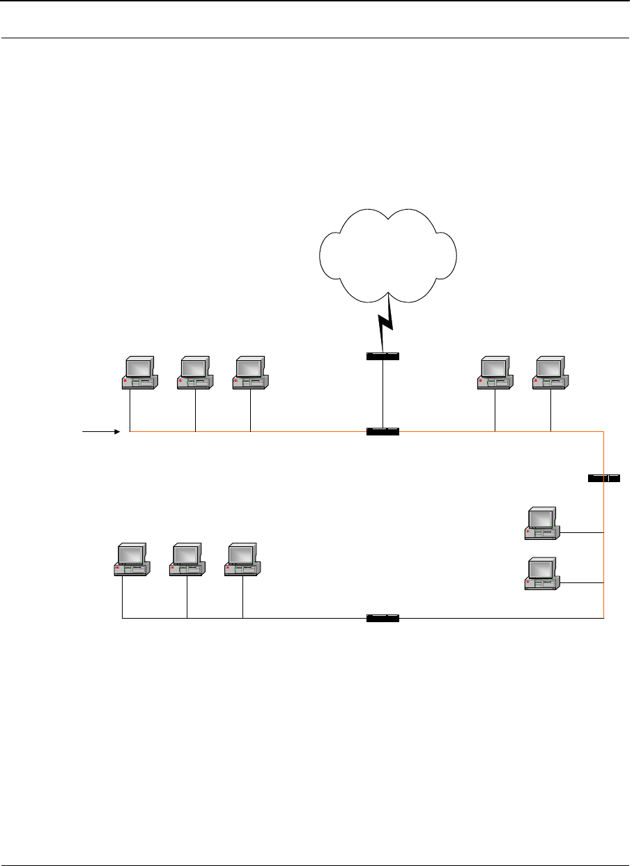
Version 3.03 SPEEDLAN 9000 Series Installation and Operation User Guide
9-6 Basics of IP Addressing
If Router D is reading IP Addresses 192.0.2.1 (let's call this IP Address 1) and
192.0.2.64 (let's call this IP Address 2) on this Class C network, it would send IP
Address 1 to Subnet A and IP Address 2 to Subnet B. The remaining nodes in each
subnet (A through D) on this network can contain up to 254 pieces of network
equipment (computers, printers, fax machines, bridges or routers, etc.).
Diagram of Subnetting a Network
Figure 9-1: Subnetting diagram
Still confused?
An easier method to explain this concept is to use the classic "mailing" analogy used in
IP addressing. Consider that this network, called Long Street, is four blocks long. There
are 254 houses on Long Street, and each block contains 64 houses. Houses 1 to 63
reside on Block A. Houses 64 to 127 reside on Block B. Houses 128 to 191 reside on
Block C. Houses 192 to 254 reside on Block D. Think of each block as a subnet. This
Internet
Router D
Router B
Router C
Computer Computer
Computer
Computer
Computer Computer Computer
Computer Computer Computer
Long Street
Subnet A
IP Address: 192.0.2.1
Subnet Mask: 255.255.255.192
Subnet B
IP Address: 192.0.2.64
Subnet Mask: 255.255.255.192
Subnet C
IP Address: 192.0.2.128
Subnet Mask: 255.255.255.192
Subnet D
IP Address: 192.0.2.192
Subnet Mask: 255.255.255.192
Router A

SPEEDLAN 9000 Series Installation and Operation User Guide Version 3.03
Basics of IP Addressing 9-7
means that Blocks A, B, C, and D are all part of Long Street, which is also known as the
network in this example. The mailman would organize the letters (or IP addresses for
network equipment) by creating four piles (one for each block, or subnet). As soon as
the mailman picks up pile A in his hand, he knows which block to turn on. This same
reasoning applies to piles B, C, and D as well. Router D knows exactly which subnet to
transfer (or turn) the packets to by reading its IP and subnet mask address. Note that
each subnet on this network is 255.255.255.192. Why is 192 the last octet in the
subnet mask and not 64? The last octet, 192, is the mask that allows 64 "houses" to
know that the mailman (or router) is coming in advance. The "houses" will know it's
mailman "Jim" by looking at the IP number.
Note: If the network is managed by a Simple Network Management Protocol for
local or Internet access, each interface must contain a unique IP Address.
This is a benefit of static or dynamic addressing.
How does a network administrator assign an IP address?
IP addresses are supplied by the network administrator, the ISP, or hosting company.
The two types of IP addressing—manual (static) and automatic (dynamic) addressing—
are described below.
•Manual (static) Addressing - Is ’Manually Configure’ option on
Interfaces Parameters page of 9000 Configuator
Each device connected to the Internet must have its own unique IP address.
Also, if a computer is being used as a server, you will assign it a permanent IP
address. This enables other computers to connect to it. Static addressing is
also beneficial to users that need to maintain a "constant" connection to the
Internet. This will enable users to easily access the IP address.
•Automatic (dynamic) Addressing - Is ’Use DHCP’ option on Interface
Parameters page of 9000 Configurator.
A DHCP (Dynamic Host Configuration Protocol) server assigns the IP address
to each computer as the computer connects to the network. If a computer
moves to a new network (i.e., great for temporary employees or mobile users),
it must be assigned a new IP address for that network. DHCP can be used to
manage these assignments automatically. DHCP is described in further detail
below.

Version 3.03 SPEEDLAN 9000 Series Installation and Operation User Guide
9-8 Basics of IP Addressing
What is DHCP?
Dynamic Host Configuration Protocol (DHCP) allows network administrators to assign
dynamic IP addresses for the period of time needed to connect to the Internet. Think of
DHCP as leasing an apartment. A prospective tenant may not need to live in an
apartment for two years, maybe just a year. Therefore, the tenant will only sign a one-
year lease agreement. For example, each time a computer is set up to connect to the
Internet, the network administrator uses DHCP to automatically assign the computer a
unique IP address. That computer will give up its IP address when it is no longer needed
(when the lease has ended) allowing new a computer (or a new tenant) on the same
network to use it. This benefits educational and corporate settings where users often log
on to different computers. In this case more IP addresses outnumber computers
because you can quickly reconfigure the network if needed from a centralized location.
Servers that utilize DHCP resolve security issues, costly IP addressing services, and
compatibility problems. DHCP is an alternative to BOOTP, which reduces the agony of
assigning static IP addresses and also provides advanced configuration options.
Note: The figure on the next page may help you understand how DHCP assigns
and IP address.
SPEEDLAN 9000 Series Installation and Operation User Guide Version 3.03
Basics of IP Addressing 9-9
Figure of DHCP Addressing
Figure 9-2: DHCP client and server
1The client asks DHCP server for IP address and configuration if needed.
2The DHCP server assigns an available IP address to client.
3The client takes IP address from DHCP server and requests any additional
configuration needed.
4DHCP server confirms IP address and configuration.
What is NAT?
Network Address Translation (NAT) is the conversion of an Internet Protocol address (IP
address) used within one network to a different IP address within another network. One
network is designated the inside network and the other is the outside network.
Network Address Translation (NAT) occurs when there is a translation among an
Internet Protocol (IP address) used within one network (designated as inside network) to
a different IP addresses within another network (designated as outside network).
Network Address Translators (NATs) allow companies to decrease the number of global

Version 3.03 SPEEDLAN 9000 Series Installation and Operation User Guide
9-10 Basics of IP Addressing
IP addresses. This enables companies to communicate with other devices on the
Internet with a single global IP address (or more than one IP address).
For example, a company can provide its clients with one IP address, allowing access to
the company's firewall only. This IP address is not a "real" address on the company's
internal network, but it is successfully translated to the correct IP location through NAT
(i.e., NAT router). Therefore, the company controls access through firewalls and
provides multiple IP addresses to outside customers without excessive limited resources,
or "global" Internet IP protocols.
NAPT
What differentiates NAPT from NAT? NAPT (or Network Address Port Translation) not
only translates the IP address but also the transport layer port. Thus, if an inbound
packet addressed to port 80 on the NAPT device would be translated and passed to the
private network's web server. Without port translation, the NAT device has no means of
knowing which host in the private network can pass packets to other devices. For an
example see, Diagram of Incoming NAT, page 9-12.
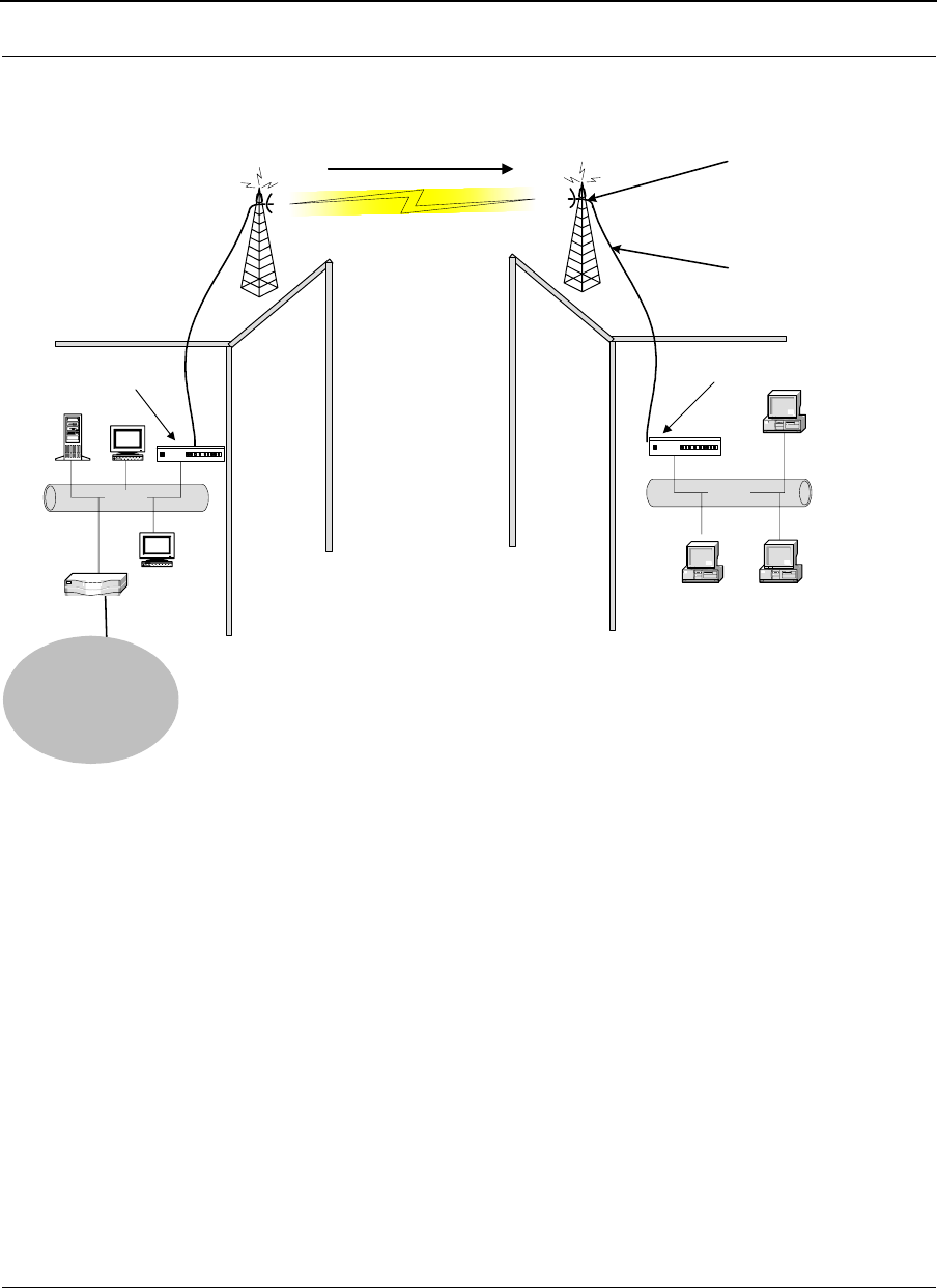
SPEEDLAN 9000 Series Installation and Operation User Guide Version 3.03
Basics of IP Addressing 9-11
Diagram of Outgoing NAT
Figure 9-3: Outgoing NAT
As the packet is transmitted from the private network (in Building B) across the public
network (public address in Building A and the Internet), the packet will be re-addressed
as 192.0.2.3 (public address). When the packet returns to Building B, the packet will
be re-addressed to the IP address of the private network by using the MAC address
contained in the header to identify the destination.
Inbound Port 80 request is re-addressed
to Private address 10.0.0.3. Then, it is
forwarded across the private network
Ethernet
Router
192.0.2..1
Private Address on Local Interface
10.0.0.1
10.0.0.2
10.0.0.4
Ethernet
Public Address on Remote Interface
192.0.2.3
Building A Building B
SPEEDLAN 9000 Router
192.0.2.0
SPEEDLAN 9000 Router
10.0.03
–
Internet
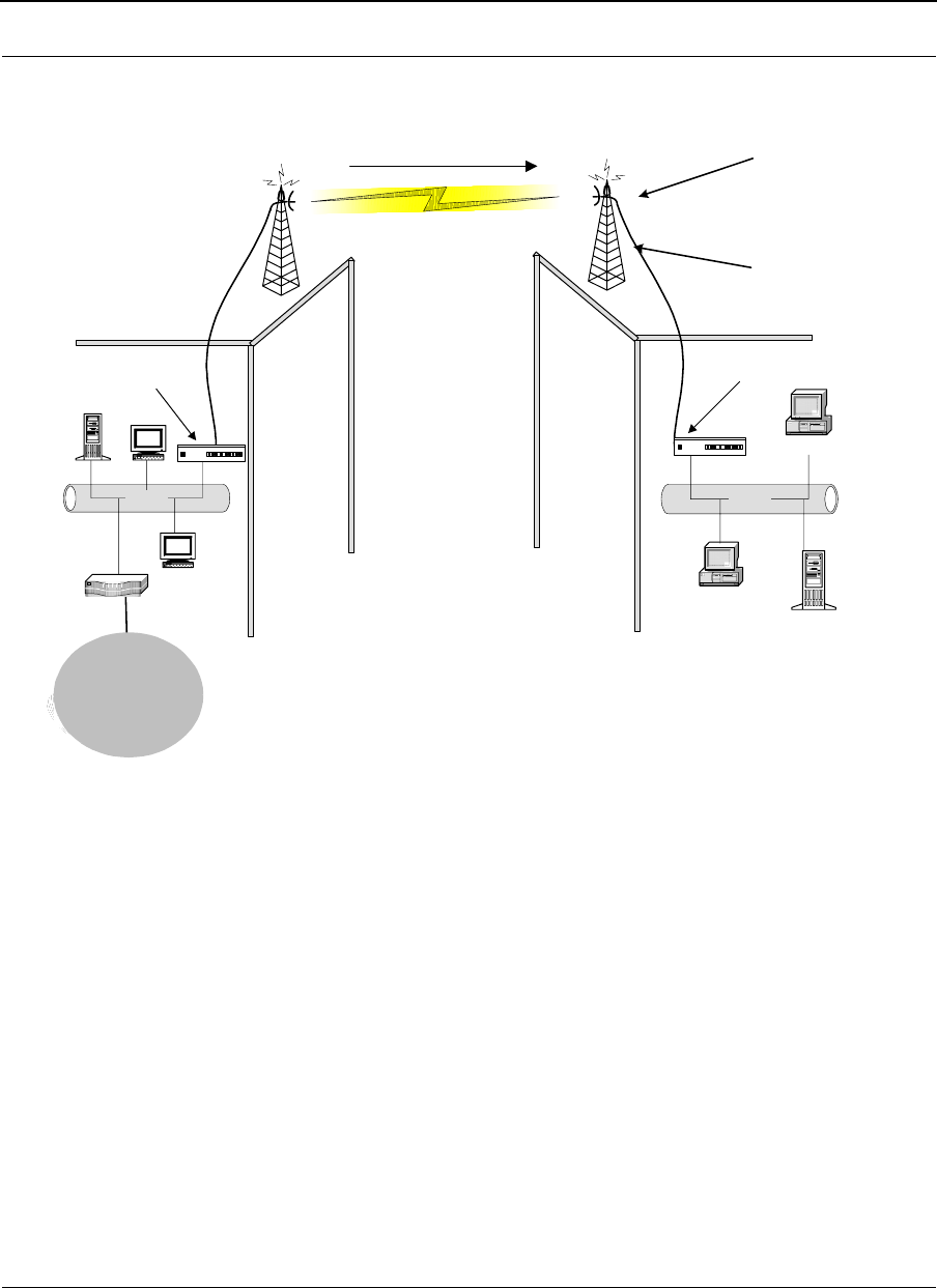
Version 3.03 SPEEDLAN 9000 Series Installation and Operation User Guide
9-12 Basics of IP Addressing
Diagram of Incoming NAT
Figure 9-4: Incoming NAT
Incoming NAT allows you to specify ports on the private network (Building B) that you
would like to be available on the public network (Building A and the Internet). For
example, if a web server (IP Address 10.0.0.3) is being hosted on a private network in
Building B, you can create a pair that will specify that all requests on the public IP
address, Port 80, be forwarded to IP Address 10.0.0.3 on the private IP address, Port
80.
Inbound Port 80 request is re-addressed
to Private address 10.0.0.3. Then, it is
forwarded across the private network
Internet
Ethernet
Router
192.0.2.1
Private Address on Local Interface
10.0.0.1
10.0.0.2
10.0.0.4
Ethernet
Web Server
10.0.0.3
Public Address on Remote Interface
192.0.2.3
Building A Building B
SPEEDLAN 9000 Router
192.0.2.0
SPEEDLAN 9000 Router
Internet

SPEEDLAN 9000 Series Installation and Operation User Guide Version 3.03
Basics of IP Addressing 9-13
Basics of Routing
A router connects two or more networks together and decides which direction it should
send each packet. The router is located at each gateway (where one network meets
another). A router operates at the Network Layer of the OSI model. This means a router
sends information based on the packet's IP address instead of the Ethernet address (as
in bridging).
Routing protocols use special metric algorithms when determining the best path for a
packet to travel. All of this information is stored in a routing table. Some of this
information includes hop count and destination information. The routing table also
stores when the receiver gets the packet and lets the sender know that is was received.
Note: For more information about routing, see www.whatis.com, http://
www.techweb.com/encyclopedia/, http://www.computeruser.com/resources/
dictionary/dictionary.html, or search for "basics of routing" on the World Wide Web.

Version 3.03 SPEEDLAN 9000 Series Installation and Operation User Guide
9-14 Basics of IP Addressing
Notes:_____________________________________________
__________________________________________________
__________________________________________________
__________________________________________________
__________________________________________________
__________________________________________________
__________________________________________________
__________________________________________________
__________________________________________________
__________________________________________________
__________________________________________________
__________________________________________________
__________________________________________________
__________________________________________________
__________________________________________________
__________________________________________________
__________________________________________________
__________________________________________________
__________________________________________________
__________________________________________________
__________________________________________________
__________________________________________________
__________________________________________________

Glossary for Standard Data
Communications

Version 3.03 SPEEDLAN 9000 Series Installation and Operation User Guide
Glossary-2
Glossary for Standard Data Communications
Alignment
In order to create a successful link, all related equipment should be associated to its respective attachments
or equipment.
Amplitude
The magnitude of a waveform when measured from the mid-point to the peak of the wave.
Analog
A signal in the form of a continuously varying quantity such as voltage, frequency or phase.
Antenna
Device used to concentrate and direct the energy of a signal into a tight beam. Parabolic or dish, grid, and
Yagi are different varieties of antennas.
Antenna Gain
The ratio of the power radiated by an antenna in a specific direction versus the power required to produce
this same strength if an isotropic antenna were used.
Attenuation
The measure of the loss of power in a microwave signal as it travels between two points. It is measured in
decibels (dB).
Attenuator
Attenuators simulate antennas during bench tests.
Azimuth
This is the direction of antenna pointing relative to true north.
Band
A portion of the electromagnetic frequency spectrum.
Bandwidth
The range of frequencies over which a device will transmit information.
Bit
An abbreviation for binary digits.

SPEEDLAN 9000 Series Installation and Operation User Guide Version 3.03
Glossary-3
Bit Error Rate
A measure of the number of errors in a digital transmission. Typically given as an exponential number that
represents the ratio of errors to total bits. Example: 1E-03 = 0.001 = 1.0 x 10⁻³ and 1.0E-6 = 0.000001
= 1.0 x 10⁻³. A single element in a binary code. A measure of the number of errors in a digital
transmission. Typically given as an exponential number that represents the ratio of errors to total bits.
Example: 1E-03 = 0.001 = 1.0 x 10⁻³ and 1.0E-6 = 0.000001 = 1.0 x 10⁻³.
Bridge
The function of a bridge is to connect separate networks together. This device operates at the DataLink Layer
of the OSI model. Bridges connect different network types (such as Fast Ethernet and Ethernet) or networks of
the same type. Bridges allow only necessary traffic to pass through the designated segments. When the
bridge receives a packet, the bridge determines the destination and source segments. If the segments are the
same, the packet is dropped, or filtered. If the segments are different, then the packet is “forwarded” to the
correct segment. Additionally, bridges do not forward bad or misaligned packets. Bridges are also called
“store-and-forward” devices because they look at the whole Ethernet packet before making filtering or
forwarding decisions. Filtering packets, and regenerating forwarded packets enables bridging technology to
split a network into separate collision domains.
Byte
A data unit consisting of eight bits.
Cable
A transmission medium of copper wire or optical fiber wrapped in a protective cover.
Channel
A specific band of frequencies designated for a specific purpose; the data path between two nodes.
Channel Service Unit/Data Service Unit (CSU/DSU)
Manages digital transmission and monitors signals for problems. Performs many functions similar to a
modem with the exception of converting digital signals to/from analog since the end device and transmission
facility are both digital.
Channel Spacing
The amount of space signals can flow through.

Version 3.03 SPEEDLAN 9000 Series Installation and Operation User Guide
Glossary-4
Class
Understanding this methodology is difficult, even for customers. Therefore, let’s explain this in easier terms.
The first octet (or octets) defines the “class” (indicated by the word “net” in this example) of the address,
which is the only method to tell the size of the network (how big) and where the internet address belongs. The
remaining octets indicate availability for network equipment (i.e., computer or other network equipment). The
three main classes are: Class A, Class B, and Class C.
•Class A: Net, Node, Node, Node 255.0.0.0 (last three octets are available for equipment)
•Class B: Net, Net, Node, Node 255.255.0.0 (last two octets are available for equipment)
•Class C: Net, Net, Net, Node 255.255.255.0 (last octet is available for equipment)
Coaxial Cable
A type of transmission line consisting of a center conductor wire surrounded by insulation that is in turn
surrounded by a conductive shield made of metal foil or wire braid. Often used to connect the RF unit and
modem unit of a wireless system.
Code Division Multiple Access (CDMA)
A system in which all users occupy the same bandwidth. Uncorrelated codes are used to allow for higher
bandwidth occupancy. This is also known as the spread spectrum system.
Common Management Information Protocol (CMIP)
A network management protocol that is consistent with an Open Systems Interconnection (OSI) network
communication model.
Company name
This is the name of the company that owns or maintains the radio given to the terminal.
Console
This device allows you to communicate through the Telnet client to access the configuration software.
Crimp
Crimp the connector to secure the conductors.
Customer Premise Equipment (CPE)
Any equipment located at the customer site. Usually in reference to those that are connected to a network.

SPEEDLAN 9000 Series Installation and Operation User Guide Version 3.03
Glossary-5
Data Communication Equipment (DCE)
A definition of an interface standard that determines how it is connected to another device. For most
modems, it resolves issues of interface between Data Terminal Equipment (DTE) and the network.
Data Terminal Equipment (DTE)
Hardware that provides for data communications. See also DCE above.
dBm
Decibels (dB) relative to 1 milliwatt.
dBw
Decibels (dB) relative to 1 watt.
Decibel (dB)
The standard unit of measurement for expressing relative signal power. It is dimensionless and is instead
referenced to a certain level.
DHCP
DHCP servers provide efficient use of IP addresses by assigning them dynamically or statically to the wireless
router location. DHCP allows network administrators to dynamically assign IP addresses for the period of
time needed to connect to the Internet or network. By providing a DHCP server within the CPE and the base
station, the SPEEDLAN 9000 series allows the DHCP transactions to be handled locally at the remote
building. This reduces the load on the entire wireless network.
Diffraction
The distortion of a wave as it is partially obstructed by an object in its path.
Digital Signal Processor (DSP)
A specialized computer chip designed to perform speedy and complex operations on digitized waveforms.
Direct Sequence (DS)
A type of spreading technique that multiplies a higher rate PN code to the signal in order to spread the
energy of the narrow band signal over a much wider bandwidth for transmission.
Direct Sequence Speed Spectrum (DSSS)
DSSS may be seen as the result of two processes. Data is multiplied with a higher rate digital sequence
(spreading code). The sequence has many “chips” for every data bit. The resultant signal modulates the RF
carrier.

Version 3.03 SPEEDLAN 9000 Series Installation and Operation User Guide
Glossary-6
E1
European Standard also used in South American nations, among others. Speed is 2.048 Mega bits per
second (Mb/s). Uses the G.703 data interface.
Elevation
1. Height above sea level. 2. The vertical angle in degrees between the ground and the direction the antenna
is pointed.
Encryption
The method of converting data into a form that cannot be understood by unauthorized people. Encryption is
very important when using wireless communication because wireless circuits are easier to tap into than
wireless circuits. There is also strong encryption, which means ciphers are used to make uncoding the signal
almost impossible, unless you have the decryption keys.
ESD
Electro-Static Discharge happens when there is a transfer between objects at diverse voltages.
Ethernet
This is the most popular physical layer LAN technology in use today. Other LAN types include Token Ring,
Fast Ethernet, Fiber Distributed Data Interface (FDDI), Asynchronous Transfer Mode (ATM) and Local Talk.
Ethernet is popular because it strikes a good balance between speed, cost and ease of installation. These
benefits, combined with wide acceptance in the computer marketplace, create the ability to support virtually
all-popular networks and make Ethernet an ideal networking technology for most computer users today. The
Institute for Electrical and Electronic Engineers (IEEE) defines the Ethernet as IEEE Standard 802.3. This
standard defines rules for configuring an Ethernet, as well as specifying how elements in an Ethernet network
interact with one another. By adhering to the IEEE standard, network equipment and network protocols will
communicate efficiently.
Ethernet Switch
This device helps expand the Ethernet network. LAN switches can link four, six, ten or more networks together,
and have two basic architectures. This switch “cuts through” and “stores and forwards” as well. This
technique takes more time to examine the entire packet, but it allows the switch to catch certain packet errors
and keep them from propagating through the network. A switch also operates between the DataLink and
Network Layer of the OSI model. It reads the MAC address and will either bridge it to the Physical Layer or
route to the Network Layer.

SPEEDLAN 9000 Series Installation and Operation User Guide Version 3.03
Glossary-7
Fade Margin
The difference between the receiver signal input level and the receiver sensitivity. Fade margin is usually
considered the safety factor allowing the system to remain operating under additional forms of attenuation.
Fading
The loss of signal strength due to changes in the atmosphere.
Fault
This section of the browser gives the user a detailed list of alarm activity. Along with the alarm activity, the
Event Log also time stamps an alarm, so the user is able to determine when an event occurred, and at what
time the event cleared. The date and time fields are derived from the time read by the radio on the network
time server.
Federal Communications Commission (FCC)
Government organization appointed by the U.S. President that regulates interstate communications (by use of
licenses, standards, rates, etc.).
Firewall
A firewall protects resources in a private network from the users on outside networks. It can also restrict
unwanted traffic from the private network to the outside. The firewall determines based on a set of rules
whether packets should be forwarded to their destination.
Firmware
Alterable programs in semitransparent storage (e.g., some type of read-only or flash reprogrammable
memory).
Forward Error Correction (FEC)
The ability of a receiving station to correct a transmission error. The transmitter sends redundant information
along with the original bits and the receiver uses this information to find and correct errors. This can increase
the throughput of a data link operation.
Framing
Dividing data for transmission into groups of bits, and adding a header and a check sequence to form a
frame.
Frequency
The number of complete cycles per second existing in a waveform. Note that frequency is measured in Hertz
(Hz).

Version 3.03 SPEEDLAN 9000 Series Installation and Operation User Guide
Glossary-8
Frequency Hopping (FH)
A type of spreading technique using a PN code to change the signal’s frequency between several
pre-assigned values (hopping). Although the signal itself looks like a narrow band signal at any given point in
time, it acts like a spread signal because of the frequency hopping.
Fresnel Zone
An imaginary ellipse surrounding the direct transmission path formed by all the points from which a reflected
wave would have an increased path length of multiple of the transmitted signal’s wavelength. At least 60% of
the Fresnel zone must be unobstructed.
Full Duplex
Independent, simultaneous two-way transmission going in both directions.
Gain
The increase in signal power caused by a device such as a transmitter or antenna.
GHz
GigaHertz. Billions of Hertz.
Ground elevation
This is the approximate mean sea level (AMSL) of the terminal.
Half Duplex
A one-way directional communication line going in both directions. Only one signal can be transmitted or
received at a time
Hertz (Hz)
A unit of measurement equal to one cycle per second.
Hexadecimal (Hex, or H)
A Base-16 numbering system. This means 16 sequential numbers are used as a base unit
(i.e., “0-9” and “A-F”).
Hop
A term used to describe a single radio path between two points.

SPEEDLAN 9000 Series Installation and Operation User Guide Version 3.03
Glossary-9
Host
This term is interchangeable with the definition “node,” which means this is a point on the network. The host
is also any device on the network that has two-way communication to any point on the network, as well as the
Internet.
Hot-standby
A condition whereby when the primary method of communication goes down, the secondary method instantly
takes over.
Hub
This device on a network collects, receives, and repeats data to its forwarded destination on the network. A
hub is also known as a switch.
HyperTerminal
This provides you details of the internal configuration of the ODU. In the HyperTerminal, you can also change
the port settings for the modem connection and adjust the settings to make a call.
IDU
Indoor Unit (i.e., Modem Unit).
IF Cable
In an SPEEDCOM system, this is the coaxial cables that connects the modem unit to the RF unit. These cables
are terminated with male TNC-type connectors at both ends.
Interface
The standard signal for connecting a microwave system to the connecting equipment.
Interference
Unwanted signals that cause performance degradation or loss of information.
Intermediate Frequency (IF)
The frequency to which a microwave signal is converted to permit signal processing. This range is typically
around 70 to 200 MHz.

Version 3.03 SPEEDLAN 9000 Series Installation and Operation User Guide
Glossary-10
Internet
This is a system of linked networks that are worldwide in scope and facilitates data communicate service such
as remote login, file transfer, electronic mail, the World Wide Web and newsgroups. With the meteoric rise of
demand for connectivity, the Internet has become the communications highway for millions of users. The
Internet was initially restricted to military and academic institutions in its infancy, but now it is a full-fledged
information channel for any and all forms of information and commerce. Internet web sites now provide
personal, educational, political and economic resources to every cornet of the planet.
IP Address
This address tells the network how to locate the computers or network equipment connected to it. IP
addresses are given so each computer or equipment on the network contains a unique address. There are
two methods used when assigning an IP address:
• Automatic (dynamic) Addressing
A DHCP (Dynamic Host Configuration Protocol) server assigns the IP address to each computer as
the computer connects to the network. If a computer moves to a new network (i.e., great for
temporary employees or mobile users), it must be assigned a new IP address for that network.
DHCP can be used to manage these assignments automatically.
•Manual (static) Addressing
Each device connected to the Internet must have its own unique IP address. Also, if a computer is
being used as a server, you will assign it a permanent IP address. This enables other computers to
connect to it. Static addressing is also beneficial to users that need to maintain a "constant"
connection to the Internet. This will enable users to easily access the IP address.
ISM (Industrial, Scientific, and Medical Bands)
Ranges are 900 to 928 MHz; 2.4 to 2.4835 GHz; and 5.725 to 5.85 GHz. The FCC for unlicensed use
allocated these bands with a restriction on the output power.
Isotropic
Uniform in all directions.
K2
This is a polling protocol used in star networks (line of sight). A base station polls the remote stations (Customer
Premise Equipment) and tells when and where CPEs can transmit.
Kb/s
Thousands of bits per second.

SPEEDLAN 9000 Series Installation and Operation User Guide Version 3.03
Glossary-11
KHz (KiloHertz)
Thousands of Hertz. Each wireless phone call occupies only a few KiloHertz.
LAN
This is a local area network that enables computers, network equipment, or other peripherals to
communicate on a small network.
Last mile
Any type of telecommunications technology where data (voice, video, etc.) is traveled within relatively short
distances to maintain to highest quality of bandwidth and throughput.
Latitude
This is the geographic latitude of the location of the terminal.
LED
This is a light-emitting diode, which is a semiconductor, that sends out visible light when an electrical current
moves through it.
Light Emitting Diode (LED)
An electronic device that emits light with little generation of heat.
Line Interface Unit (LIU)
The first unit inside the modem units encountered by signals from the user.
Line of Sight (radio) (LOS)
A condition whereby the antennas of a given link have a sufficient path for communication. It requires that at
least 60% of the Fresnel zone between them be unobstructed. (Do not confuse with Loss of Signal.)
Local Area Network (LAN)
A short distance data communications network used to link together computers and peripheral devices
(such as printers) under some form of standard control.
Loopback
This is the process of sending out a test signal to the device on the network so that you know if your signal
was successful or unsuccessful.

Version 3.03 SPEEDLAN 9000 Series Installation and Operation User Guide
Glossary-12
Loss of Signal (LOS)
The signal from the user’s device does not appear in the DSX or E1 interface. (This is not to be confused with
Line of Sight.)
MAC address
In a LAN environment each computer contains its own Medium Access Control (MAC) address which is the
embedded and unique hardware number. For computers on Ethernet LANs, this is the same number as its
Ethernet address. This address is controlled at the DataLink Layer of the OSI model, and is in a hexadecimal
format separated by four octets (i.e., 82.39.1E.38).
MAN
This is a metropolitan network that enables computers, network equipment, other peripherals, and more than
one LAN to communicate within the city or nearby limits.
Management Information Base (MIB)
A database of network parameters used by SNMP and CMIP to monitor and change network device settings.
It provides a logical naming of all information resources on the network pertinent to the network’s
management.
Mean Time Between Failure (MTBF)
A measure of the theoretical times a component or device will operate without failing.
MHz (MegaHertz)
Millions of Hertz.
Modulation
The process of varying characteristics of a carrier signal to represent changes in the transmitted information.
MOdulator-DEModulator (MODEM)
A device that converts a digital signal to analog, or vice versa, and is used to transfer data between
computers over communications lines.
Mb/s
Million of samples per second.

SPEEDLAN 9000 Series Installation and Operation User Guide Version 3.03
Glossary-13
Multi-path fading
The condition in which the “true” signal from an antenna reflects off an object (usually the ground) and, as a
result, the reflected signal causes destructive interference at the receiving antenna. Multi-path fading affects
linearly polarized signals more than circularly polarized signals.
NAT
NAT helps to ensure network security and allows an entire company to share a single global IP address for
communication on the Internet. This enables companies to communicate with other devices on the Internet.
Network
A set of connections that allow them to exchange data with each other, which enables multiple users to share
to communicate data through the accepted path(s). Two or more locations tied together with equipment and
communications channels.
Node
This is a point on the network such as a computer, server, peripheral (printer, scanner, etc).
Noise
Any unwanted signal or disturbance that degrades the quality of a transmitted signal.
Obstruction
Any man-made or natural object that blocks, diffracts, or reflects a transmitted signal.
Octet
There are four octets in an IP address. Each octet contains 8 bits, which are equivalent to 1 byte. Each octet
is separated by a period (.).
OD
Outside diameter of pipe for mounting an antenna.
Outdoor Unit
The Outdoor Unit (ODU) provides the baseband and RF signal processing required to convert the 100Base-
T signal from the CPI to an RF frequency at 23, 26, 29, or 38 GHz. The ODU mounts to an antenna through
an integral “Quick-Fit” connection that does not require any external waveguide. The ODU housing is
ruggedized to protect the RF and modem electronics contained inside. It is capable of simultaneously
transmitting and receiving 100 Mb/s of data traffic over the air.

Version 3.03 SPEEDLAN 9000 Series Installation and Operation User Guide
Glossary-14
Packet
A unit of data transmitted between a receiver and a sender. Each packet contains embedded information, as
well as place to go on the network (known from the IP address).
Part 15 (of FCC rules)
The section of the FCC Code of Federal Regulations defines the restrictions regarding the use of Spread
Spectrum systems.
Passive Repeater
A re-radiation device associated with a transmitting/receiving antenna system that re-directs intercepted
radio frequency energy without boosting or processing the signal.
Path Length
The distance between two ends of a wireless system.
Path Loss
The decrease in signal power experienced when a signal is transmitted between two points.
Path Profile
A drawing of the terrain (including buildings, trees, hills, lakes, etc.) along a transmission path to determine if
a given path is viable for the communication link. This is usually done with a computer.
Personal Communication Services (PCS)
A lower powered, higher frequency competitive technology to cellular.
Polarization
The direction of the amplitude of a radio wave. Polarization is usually horizontal or vertical.
Pole Height
This is the height of the antenna supporting structure.
Power Output
The power produced by a transmitter. This is measured in decibels per meter (dBm).
Processing Gain
The ability of the spread spectrum decoder to recover the received signal out of noise. It is essentially the
increase in ability to recover the signal in the presence of an interfering carrier of the same or greater level.

SPEEDLAN 9000 Series Installation and Operation User Guide Version 3.03
Glossary-15
Propagation
The transmission of a wave along a given path through a medium.
Protocol
A network protocol is the standard that allows computers to communicate with each other. A protocol defines
how computers identify one another on the network, the form that the data should take in transit, and how
this information is processed once it reaches its final destination. Protocols also define procedures for
handling lost or damaged transmissions or “packets.” IPX (for Novell Netware), TCP/IP (for UNIX, Windows
NT, Windows 95 and 98 and other platforms), DECnet (for networking Digital Equipment Corp. computers),
AppleTalk (for main Macintosh computers), and NetBIOS/NetBEUI (for LAN and Windows NT networks) are
some of today’s most popular networks. Although each network protocol is different, they all share the same
physical cabling. This common method of accessing the physical network allows multiple protocols to
peacefully coexist over the network media, and allows the builder of the network to use common hardware
for a variety of protocols. This concept is known as “protocol independence,” which means that devices that
are compatible at the physical and data link layers allowing the user to run many different protocols over the
same medium.
Pseudo-random Noise code (PN code)
A high rate digital code that mimics random noise-like properties. It is multiplied with a lower rate data
signal in order to achieve spread spectrum transmission signals. The receiver then multiplies the same code
back into the transmission to recover the data signal.
Public Switched Telephone Network (PSTN)
This refers to a worldwide voice telephone network accessible to all those with telephones and access
privileges.
Quadrature Amplitude Modulation (QAM)
A method for modulating a signal by which more than one bit can be sent simultaneously.
Quadrature Phase Shift Keying (QPSK)
Phase-shift keying in which there are four phase states or positions in the time or frequency domains within a
single period.
Radiation
The flow of electromagnetic energy from a transmitter.
Radiation Pattern
An illustration of the energy level radiated by an antenna in every direction.

Version 3.03 SPEEDLAN 9000 Series Installation and Operation User Guide
Glossary-16
Radio address
This is the physical location (street name) of the terminal. This is also displayed at the bottom of the web
page.
Radio Frequency (RF)
The frequency at which microwave systems transmit.
Received Signal Strength Indicator (RSSI)
The RSSI Voltage provided at the output of the RF Unit that is used to indicate the RF Input Level.
Reflection
The sharp change in direction of a wave after hitting an obstruction in its path.
Refraction
The bending of a wave as it moves from one medium to another.
Reliability
A measure of the percentage of time the system is operating. Reliability is usually a measure of both the avail-
ability of the signal and the MTBF of the equipment.
Responsible personnel
This is the person(s) responsible for maintaining the radio system.
RF Signal Level
The strength of the power received by the RF Unit from the antenna.
Router
This device filters out network traffic by specific protocol rather than by packet address. This device operates
at the Network layer of the OSI model. Routers also divide networks logically instead of physically. An IP
router can divide a network into various subnets so that only traffic designated for particular IP addresses can
pass between segments. Network speed often decreases due to this type of intelligent forwarding. Such
filtering takes more time than exercised in a switch or bridge, which only looks at the Ethernet address. In
more complex networks, overall efficiency is improved by using routers.
Rx (Receiver)
This is where the packet is going.

SPEEDLAN 9000 Series Installation and Operation User Guide Version 3.03
Glossary-17
Server
A computer that is responsible for tracking, as well as receiving and sending requests from other computers
connected to it (on the same network).
Sidelobe
These are 20 dB lower than the main lobe, and it is critical from a performance standpoint that antennas are
aligned with respect to the main lobe. Failure to do so may cause the radio to be interfered with or the radio
may interfere with other systems.
Signal level
This is the value of the signal level at the receiving end of the transmission path.
Simple Network Management Protocol (SNMP)
The standard protocol for TCP/IP network management that has the most common worldwide use.
Site ID (Unique)
This is the alphanumeric site address given to the terminal by you (the user).
Spread Spectrum Technology (SST)
A method of encoding (with a PN code) a digital signal in a transmitter so as to spread it over a wide range
of frequencies so that the average signal power is close to the noise floor. The same code is known to the
receiver and is used to decode the signal. Keeping the code secret provides communications security.
Star
A topology (in the K2 polling protocol category) that includes point-to-point or point-to-multipoint activity, as
long as those routers are within line-of-sight of each other.
Submask
This term allows you to mask section(s) (depending on the class specified) of the octets in the network
address. Each octet used in the subnet mask is assigned to a data link. The leftover octet(s) are assigned to
the remaining nodes.
Subnet
This term allows you to create multiple networks within one Class A, B, or C network. Each data link (octet)
contains its own unique identifier also known as the subnet. Also, each node on the same data link must
belong on the same subnet as well.

Version 3.03 SPEEDLAN 9000 Series Installation and Operation User Guide
Glossary-18
Symbol Threshold
After a signal has been acquired, the acquisition algorithm in the spread-spectrum chip continues to run a
cross-correlation between the expected PN sequence and the received signal, but now uses the Symbol
Threshold for comparison. If the result of the cross-correlation drops below the Symbol Threshold, the signal
is considered to have been lost, and the algorithm begins trying to acquire the signal again.
System Gain
The sum of the transmitter power output and the receiver sensitivity. System gain is an important measure of a
system’s ability to overcome attenuation and perform to a satisfactory level. These are measured in decibels
per meter (dBm).
Tx (Transceiver)
This is where the packet is coming from.
WAN
A wide-area metropolitan network is a connection between LANs, which may be privately owned or rented.
Wired
A network interface connected by wire to other nodes in the network.
Wireless
A network interface that uses radio to communicate to other nodes in the network.

Appendices
The Appendices include:
•Appendix A - Changing the Router’s Topology Mode
•Appendix B - IP Recovery
•Appendix C - Passwords for the SPEEDLAN 9000
Configurator, SPEEDView & IP Recovery
•Appendix D - Declarations of Conformity and
Regulatory Information
•Appendix E - 9000 Technical Specifications & Product
Model Information
•Appendix F - SPEEDSignal

SPEEDLAN 8100 & 8200 Installation and Operation User Guide
-2 Appendices

Appendix A - Changing the
Router’s Topology Mode

Version 3.03 SPEEDLAN 9000 Series Installation and Operation User Guide
Change Topology Mode (Appendix A)-2
Changing the Router's Topology Mode
This tutorial tells you how to change the router's topology mode (base station, CPE,
point-to-point or mesh) from or to another topology mode (base station, CPE, point-to-
point or mesh).
1Enter the correct URL or IP address for the router in your web browser.
2Enter the correct password and click Login. If you do not want to reset all
configuration to the Factory Default, skip to step 6.
3Reset all configuration to the factory defaults. Do this by choosing Factory
Reset from the Admin menu. Then, click Reset All Configuration to the
Factory Default.
4The system will reboot the router.
5When the router is back up, log in again to the default IP address of
192.168.69.1.
Note: You can also use the IP Recovery application to assign a temporary IP address
that is compatible to your existing network. For information on how to set up a
temporary IP address, see What is IP Recovery?, IP Recovery, Appendix A-2.
6Choose Interfaces under the Network menu. The Network Interfaces page
will appear. Select the new mode (e.g., Mesh) from the Interface Type drop-
down menu. Then, click Apply.
7The system will reboot the router.
8Now you can configure any other router parameters as needed.

Appendix B - IP Recovery

Version 3.03 SPEEDLAN 9000 Series Installation and Operation User Guide
IP Recovery (Appendix B)-2
What is IP Recovery?
Primary Use: If you changed the IP address on the router and forgot it, you can find the
configured IP address of the Ethernet interface using IP Recovery.
Secondary Use: If after learning the IP address of the Ethernet interface, you cannot
log on to the router using the HTML Configurator (SPEEDLAN 9000 Configurator), then
you will be able set a temporary Ethernet IP address so that a connection can made.
This will allow you to troubleshoot the problem. It does not change the existing IP
address on the Ethernet. After you have fixed/checked the settings on the router, reboot
the router and the temporary IP address will be removed. The real IP address will be
functioning again.
Note: You can also perform a power transmit test. For more information, see page 6 of
this chapter.
Installing the IP Recovery Program
System Requirements
•Runs on the following Windows platforms: 98, ME, NT (Service Pack 4.0),
2000 or XP.
•10 Megabytes of Hard Drive Disk Space
•CD-ROM Drive (for installation)
•Monitor (monochrome is sufficient but VGA or better is highly recommended)
•This IP Recovery program is only compatible with the SPEEDLAN 9000 series
Installation Instructions
Note: You will need to make sure that you have enabled the TCP/IP protocol for your
Ethernet device before using this program.
If you install IP Recovery from the SPEEDLAN 9000 Series CD, follow these
directions:
1Insert the SPEEDLAN 9000 Series CD into your CD-ROM drive.
2Locate the zip file under the \SPEEDLAN 9000_Files\9000 Management
Software\SPEEDView_& IP Recovery & SPEEDSignal Install_Files directory.
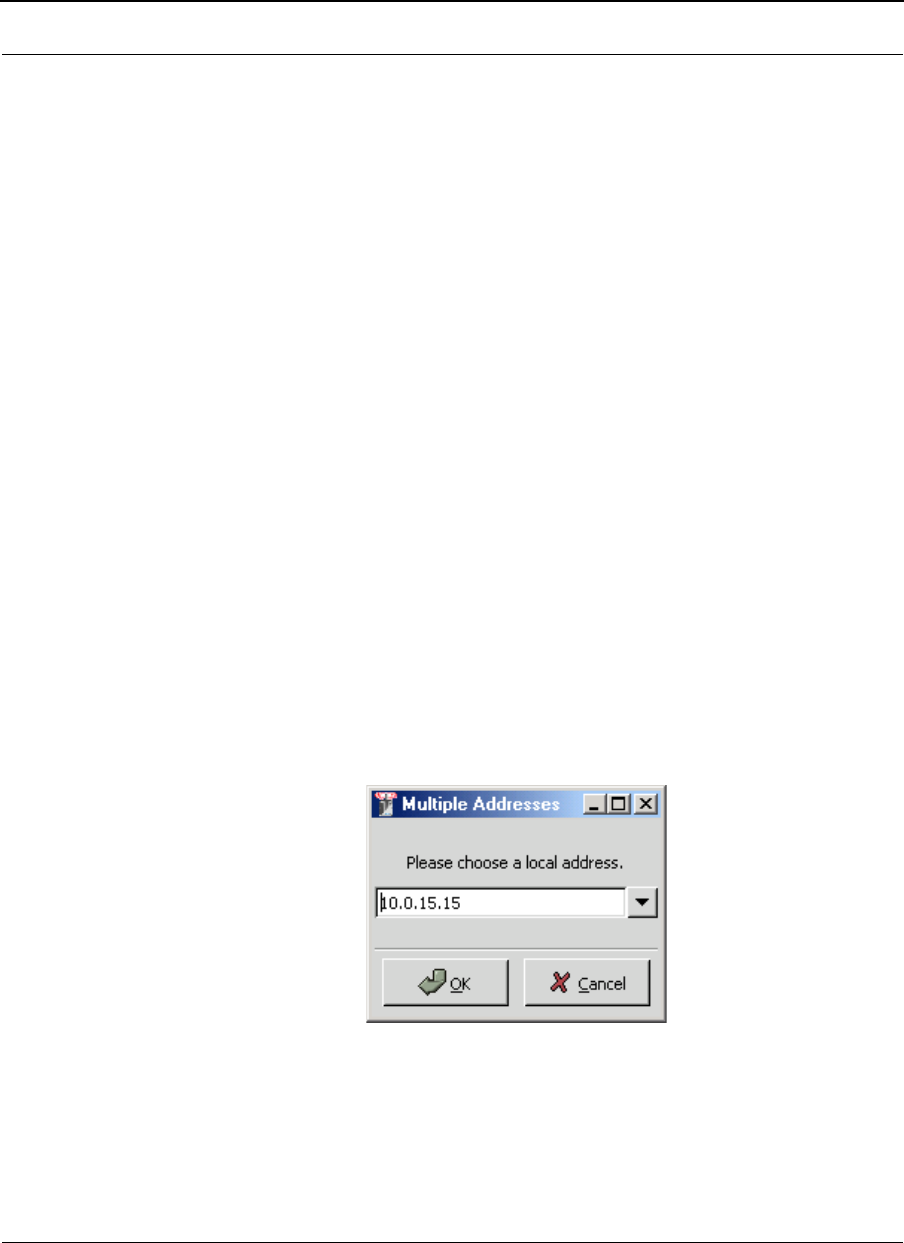
SPEEDLAN 9000 Series Installation and Operation User Guide Version 3.03
IP Recovery (Appendix B) - 3
Follow steps 1 through 5 below.
If you are installing an executable from a zip file (from our website):
Note: IP Recovery can also be downloaded from the Wave Wireless web site "Support"
directory. Locate the link and save the zip file to your desktop.
1Locate the ".zip" file and double-click it. The WinZip® dialog box will appear
on your desktop allowing you to extract the SPEEDView install files. Select the
files and click the Extract button. Next, extract the files to a location on your
computer.
2Click Start on the Windows taskbar. The Start menu appears.
3Choose Run from the Start menu. The Run dialog box appears.
4Locate the executable called setup.exe.
5Follow the installation prompts.
Starting IP Recovery
1When the installation is finished, start the IP Recovery program choosing by
the Start menu, Programs+Wave Wireless+IP Recovery. (If the IP Recovery
program was installed in another folder, select the appropriate directory.)
Note: If you have more than one IP address on your PC, this dialog box will appear
when you first launch the program.
Multiple Addresses dialog box
It will ask you which
local address you want
to select. Select it and
click OK.
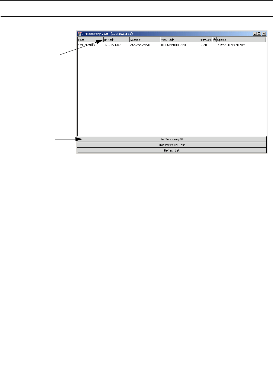
Version 3.03 SPEEDLAN 9000 Series Installation and Operation User Guide
IP Recovery (Appendix B)-4
2The IP Recovery dialog box appears.
IP Recovery dialog box
The following IP Recovery fields are displayed:
•Host: The name of the host (or RF interface) IP address if host name has
not been set in the SPEEDLAN 9000 HTML Configurator).
•IP Address: Contains the IP address of the selected router.
•Netmask: Contains the netmask of the selected router.
•MAC Address: In a LAN environment each network interface contains its
own Medium Access Control (MAC) address which is the embedded and
unique hardware number assigned to the unit.
•Firmware: This lists the firmware’s version.
•Platform: The internal hardware code to determine the type of underlying
hardware.
•Uptime: The time that the unit has been running.
Use the sliders to view
or hide IP Recovery
fields on the
dialog box.
You can als o us e the
scroll bar to view
more fields.
Click to reload the
list of units for the
wired network.
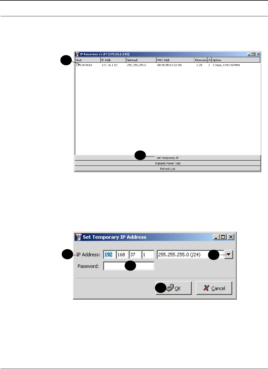
SPEEDLAN 9000 Series Installation and Operation User Guide Version 3.03
IP Recovery (Appendix B) - 5
Setting a Temporary IP Address
1Select the host for the router that you want to set a temporary address by
selecting it (as shown in the example below).
Setting a Temporary IP address
2Click the Set Temporary IP button on the IP Recovery dialog box to set a
temporary Ethernet IP address for the router. You will be allowed to enter a
temporary IP address to connect to the router. The Set Temporary IP Address
dialog box will appear as shown below.
Setting the temporary address and netmask
3Enter the temporary address in the IP Address textbox.
4Next, select the netmask for the router.
5The password entry is for full access rights only. The default password is
"wave_full". Again, this can be altered in the SPEEDLAN 9000 Configurator.
1
2
34
3
5
6
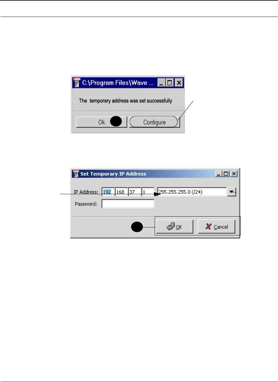
Version 3.03 SPEEDLAN 9000 Series Installation and Operation User Guide
IP Recovery (Appendix B)-6
Note: The minimum password length is 8 characters. The maximum password length is
16 characters (including the underscore character or spacebar).
6Click OK on the Set Temporary IP Address dialog box.
7Next, you will receive a message confirming that the temporary IP address has
been set, as shown below. Click OK to close this message box.
Message confirmation
8Finally, click OK or click Cancel to re-enter your settings.
Temporary IP address complete
9Now you can connect to the router via the SPEEDLAN 9000 HTML
Configurator to make any changes/configurations to the router.
Transmit Power Test
You are encouraged to use the transmit power test during installation if you have a
spectrum analyzer or power meter to measure the output for the antenna alignment. It
should not be used on a running network because it will disrupt the network for the
duration of the test. To perform a power transmit test, follow these steps:
7
Note: Clicking the Configure button
will start the SPEEDLAN 9000
Configurator using the new
temporary IP address. The Config.
will automatically enter the default
password (e.g., "wave_full").
8
displays
netmask
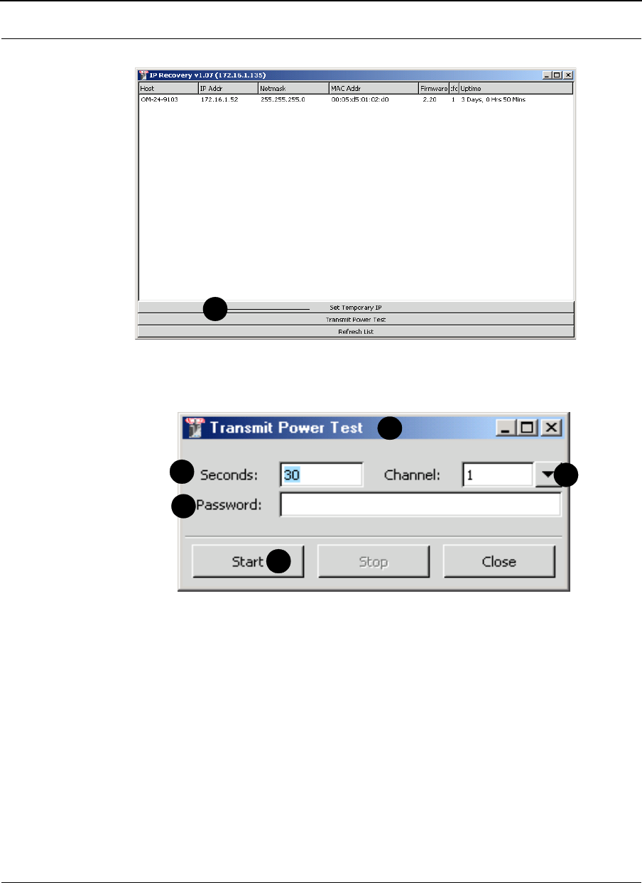
SPEEDLAN 9000 Series Installation and Operation User Guide Version 3.03
IP Recovery (Appendix B) - 7
1Click the Transmit Power Test button.
Begin Transmit Test
2The following dialog box will appear.
Transmit Power Test dialog box elements
3Enter the length of time for the power transmit test in the Seconds text box.
(The default length is 30 seconds).
4Next, enter the password in the Password textbox, depending on the type of
user access, as follows:
•Full Access (also known as a superuser): wave_full.
Note: "Full Access" does not show up in "Admin/Users" because the user
will not be able to change its permissions and it has write permission on
everything.
•Wired Admin: wave_wired_admin (account for the private Ethernet
network).
1
1
3
4
5
6
2
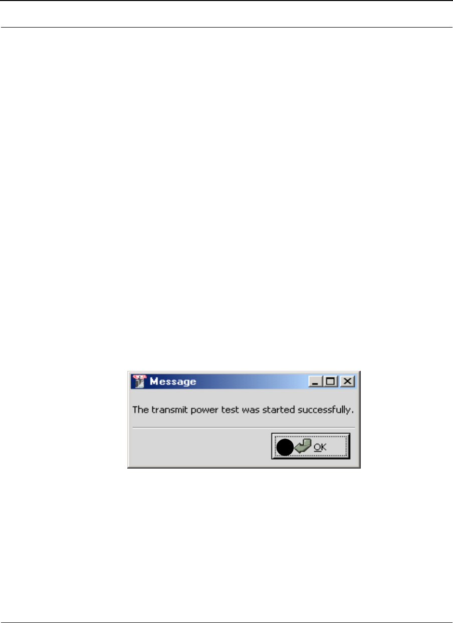
Version 3.03 SPEEDLAN 9000 Series Installation and Operation User Guide
IP Recovery (Appendix B)-8
•Wired Read: wave_wired (account for the private Ethernet network).
•Wireless Admin: wave_wireless_ad (account for the wireless SPEEDLAN
9000 network).
•Wireless Read: wave_wireless (account for the wireless SPEEDLAN 9000
network).
5Select the channel rate (from 1 to 11) from the Channel drop-down list.
•2.412 - Channel 1
•2.417 - Channel 2
•2.422 - Channel 3
•2.427 - Channel 4
•2.432 - Channel 5
•2.437 - Channel 6
•2.442 - Channel 7
•2.447 - Channel 8
•2.452 - Channel 9
•2.457 - Channel 10
•2.462 - Channel 11
6Click Start to begin the test.
7A message box will appear telling you the "test was started successfully."
Successful message
7
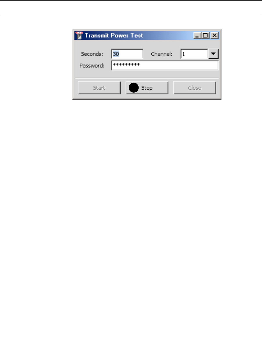
SPEEDLAN 9000 Series Installation and Operation User Guide Version 3.03
IP Recovery (Appendix B) - 9
8Click Stop when you want to stop the test.
Transmit Power Test complete
8

Version 3.03 SPEEDLAN 9000 Series Installation and Operation User Guide
IP Recovery (Appendix B)-10
Notes:_____________________________________________
__________________________________________________
__________________________________________________
__________________________________________________
__________________________________________________
__________________________________________________
__________________________________________________
__________________________________________________
__________________________________________________
__________________________________________________
__________________________________________________
__________________________________________________
__________________________________________________
__________________________________________________
__________________________________________________
__________________________________________________
__________________________________________________
__________________________________________________
__________________________________________________
__________________________________________________
__________________________________________________
__________________________________________________
__________________________________________________

Appendix C - Passwords for
the SPEEDLAN 9000
Configurator, SPEEDView & IP
Recovery
This appendix provides the passwords needed for the
SPEEDLAN 9000 Configurator, SPEEDView, IP Recovery and
SPEEDSignal.
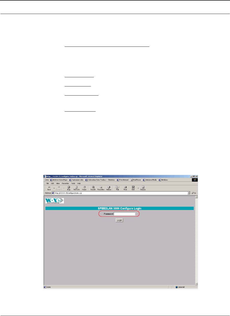
Version 3.03 SPEEDLAN 9000 Series Installation and Operation User Guide
Passwords (Appendix C)-2
SPEEDLAN 9000 Configurator and SPEEDSignal Passwords
There are five classes of users. The classes are as follows with their default passwords:
•Full Access (also known as a superuser): "wave_full"
Note: "Full Access" does not show up in "Admin/Users" because the user will
not be able to change its permissions and it has write permission
on everything.
•Wired Admin: "wave_wired_admin" (account for the private Ethernet network)
•Wired Read: "wave_wired" (account for the private Ethernet network)
•Wireless Admin: "wave_wireless_ad" (account for the wireless SPEEDLAN 9000
network)
•Wireless Read: "wave_wireless" (account for the wireless SPEEDLAN 9000
network)
Admin accounts have administration rights to their appropriate network (wired or
wireless), and Read Only accounts have only read only access.
Note: If you are a network administrator and want to modify the default passwords and
settings for any of the users, choose the Admin menu. For more information, see
Admin Menu, page 3-73.
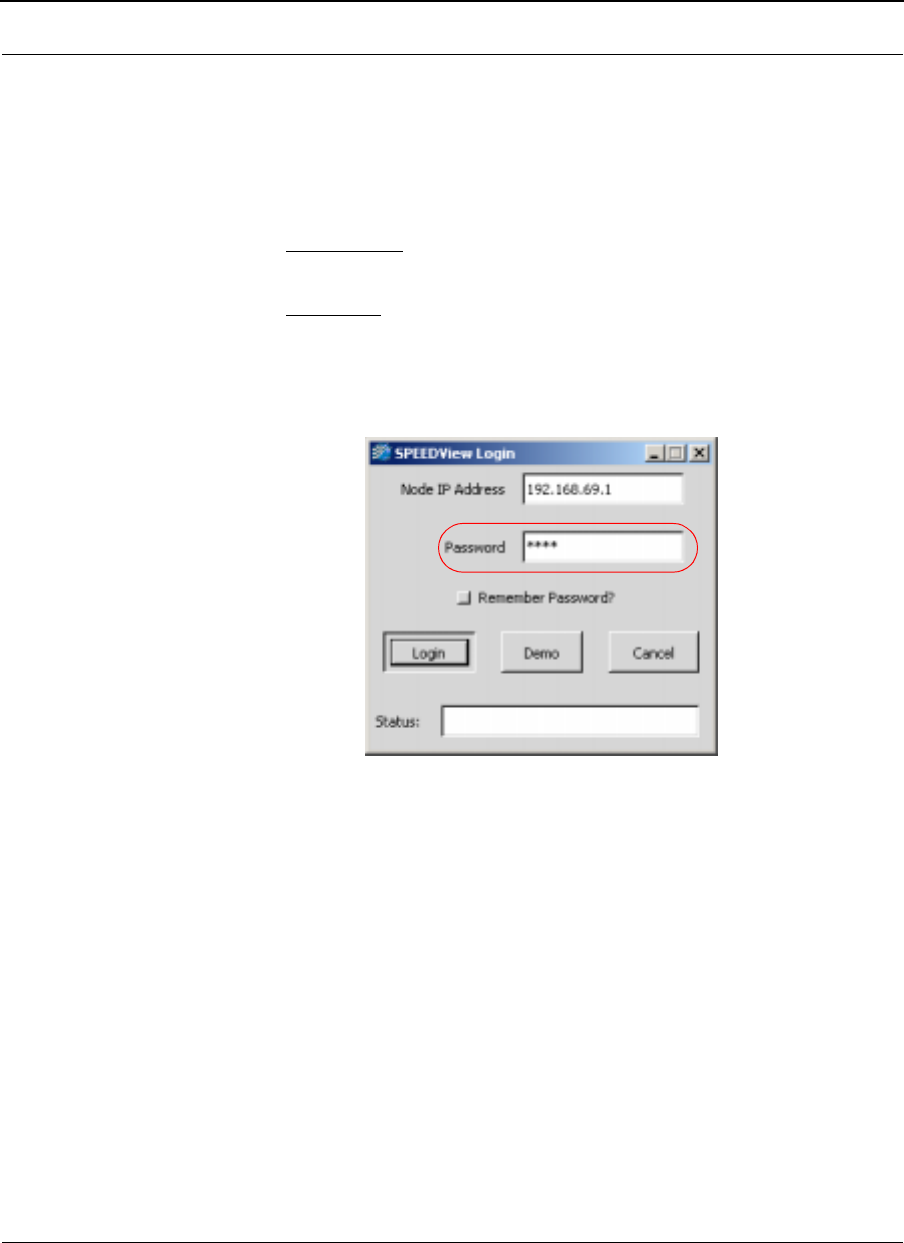
SPEEDLAN 9000 Series Installation and Operation User Guide Version 3.03
Passwords (Appendix C) - 3
SPEEDView Passwords
The passwords are defined, based on user class level, in the SPEEDLAN 9000
Configurator. Before you enter the password, decide which account level you should
enter:
•Administrator: allows access to all of SPEEDView’s features. You would
enter “wave_full” in the Password text box.
•Read Only: limits the following features: TCP dump functions, bandwidth
tests, bandwidth toolbar and block and unblock features (items under the
Link menu). You would enter “wave_wired" for wired nodes or
"wave_wireless" for wireless nodes in the Password text box.

Version 3.03 SPEEDLAN 9000 Series Installation and Operation User Guide
Passwords (Appendix C)-4
IP Recovery Password
This application uses the full access password only which is defined in the SPEEDLAN
9000 Configurator. The default full access password is "wave_full".

Appendix D - Declarations of
Conformity and Regulatory
Information
This appendix provides declarations of conformity and
regulatory information for the Wave Wireless SPEEDLAN 9000
series.
This appendix contains the following sections:
•Safety Instructions
•Manufacturers Federal Communication Commission
Declaration of Conformity Statement
•Declaration of Conformity for RF Exposure
•Manufacturers Canadian Declaration of Conformity
Statement
•European Telecommunications Standards Institute
Statement of Compliance Information to User
•Radio Approval Table

Version 3.03 SPEEDLAN 9000 Series Installation and Operation User
Regulations (Appendix D)-2
Safety Instructions
Rooftop and Tower Installations Warning
Rooftop, tower, and other mounted location equipment installations are extremely
dangerous and incorrect installation can result in death, injury, or property damage.
General Safety Requirements for Installation of SPEEDLAN
9000 Models
1The AC power socket outlet should be installed near the switching power
supply and junction box.
2It is recommended that replacement of the battery which is soldered to the PC
board should be done by manufacturer or professional installer.
CAUTION: THERE IS RISK OF EXPLOSION IF BATTERY IS REPLACED BY
INCORRECT TYPE. DISPOSE USED BATTERIES ACCORDING TO
INSTRUCTIONS.
3During installation of SPEEDLAN 9000 on the tower or on the wall,
the necessary clearance from the power and lightning conductors should be
maintained and proper grounding provided. The installation should be done
in accordance with National Electrical Code:
•NEC Article 725 – CEC Rule 16
•NEC Article 800 – CEC Section 60, and
•NEC Article 810 – CEC Section 54.

SPEEDLAN 9000 Series Installation and Operation User Guide Version
Regulations (Appendix D)- 3
Manufacturer Information
Manufacturer/Importer Name: Wave Wireless Networking
A Division of SPEEDCOM Wireless Corporation
7020 Professional Parkway East
Sarasota, FL 34240
Phone: 941-907-2300
Fax: 941-355-0219
Regulatory Information
Install this device in accordance with the instructions provided in this User Guide. To
determine the type of device you should use in your country, see the Radio Approval
Table on page 6 of this section.
Manufacturers Federal Communication Commission
Declaration of Conformity Statement
This equipment has been tested and found to comply with the limits of a Class B digital
device, pursuant to Part 15 of the FCC Rules. These limits are designed to provide
reasonable protection against harmful interference when the equipment is operated in
a residential environment. This equipment generates, uses, and radiates radio
frequency energy, and if not installed and used in accordance with the instructions,
may cause harmful interference. However, there is no guarantee that interference will
not occur. If this equipment does cause interference to radio or television reception,
which can be determined by turning the equipment off and on, the user is encouraged
to correct the interference by one of the following measures:
•Reorient or relocate the receiving antenna.
•Increase separation between the equipment and receiver.
•Connect the equipment into an outlet on a circuit different from which the
receiver is connected.
•Consult the professional installer or an experienced radio/TV technician.
Note: The manufacturer is not responsible for any radio or TV interference caused by
unauthorized modifications to this equipment. Such modifications could void the user’s
authority to operate the equipment.

Version 3.03 SPEEDLAN 9000 Series Installation and Operation User
Regulations (Appendix D)-4
Warning! This part 15 radio device operates on a non-interference basis with other
devices operating at this frequency when using the antennas: 24 dBi grid antenna and
8 dBi omni antenna.
Declaration of Conformity for RF Exposure
The radio module has been evaluated under FCC Bulletin OET65C and found
compliant to the requirements as set forth in CFR 47 Sections 2.1091, 2.1093, and
15.247 (b) (4) addressing RF Exposure from radio frequency devices. For the 24-dBi
antenna, the equipment should be positioned more than 2 m from your body or nearby
persons. For the 8-dBi antenna, the equipment should be installed more than 20 cm
from your body or nearby persons.
Manufacturers Canadian (IC) Declaration of Conformity
Statement
This Class B Digital apparatus meets all the requirements of the Canadian
Interference-Causing Equipment Regulations.
Cet appareil numerique de la classe B respecte les exigences du Reglement sur le
material broilleur du Canada. This device complies with Class B Limits of Industry
Canada. Operation is subject to the following two conditions:
1. This device may not cause harmful interference, and
2. This device must accept any interference received, including interference that may
cause undesired operation.
The device is certified to the requirements of RSS-139-1 and RSS-210 for 2.4-GHz
spread spectrum devices. The use of this device in a system operating either partially or
completely outdoors may require the user to obtain a license for the system according
to the Canadian regulations. For further information, contact your local Industry
Canada office.
!
!!
!

SPEEDLAN 9000 Series Installation and Operation User Guide Version
Regulations (Appendix D)- 5
European Telecommunications Standards Institute (CE)
Statement of Compliance
Information to User
This equipment has been tested and found to comply with the requirements of ETSI
standards. The product is in conformity with COUNCIL DIRECTIVE 89/336/EEC (EMC
Directive) and applicable safety Standards.
The Standards to which conformity is declared:
These Standards cover Wideband Data Transmission Systems referred to in the CEPT
recommendation T/R 10.01. This type of accepted equipment is designed to provide
reasonable protections against harmful interference when the equipment is operated in
a commercial environment. This equipment generates, uses and can radiate radio
frequency energy, and if not installed and used in accordance with the instructional
manual, may cause harmful interference to radio communications.
DECLARATION OF CONFORMITY is herby issued to the named Manufacturer/
Importer and is VALID ONLY for the equipment identified below:
Date of Approval:
May 25, 2002
Declares That This Product (Product Description):
2.4 GHz BAND DSSS WIRELESS LAN
Manufacturer/Importer Signature: Name: Janusz Dyndul
Date: 25 May 2002
EN 55022 1998 Class B EN 61000-4-4
EN 50082 – 1 1998 EN 61000-4-5
ETSI EN 300-328/-2 EN 61000-4-6
EN 6100-4-2 EN 61000-4-8
EN 61000-4-3 EN 61000-4-11
EN 60950-2000 EN 61000-3-2
EN 60215-1996

Version 3.03 SPEEDLAN 9000 Series Installation and Operation User
Regulations (Appendix D)-6
Radio Approvals
To determine the correct device you are allowed to use in your country, refer to the
tables below:
Radio Approval Table for Models SL910x
Country Commission Model SL910x & Certification Number
United
States
FCC NCBSL9101, NCBSL9102
Canada IC 4309A-SL9101, 4309A-SL9102
Europe
(ETSI)
CE NCBSL9104

Appendix E - 9000 Technical
Specifications & Product
Model Information
This appendix provides specifications and product model
information for the Wave Wireless SPEEDLAN 9000 series.

Version 3.03 SPEEDLAN 9000 Series Installation and Operation User Guide
Specifications (Appendix E)-2
9000 Series Technical Specifications
Radio
Type: Direct Sequence Spread Spectrum (DSSS)
Frequency: 2.4 GHz (2.4000 to 2.4835)
Channels: 11 user selectable channels
Modulation: CCK at 11 Mb/s & 5.5 Mb/s, DQPSK at 2 Mb/s, DBPSK at 1 Mb/s
Processing Gain: 11dB (Nominal)
Communication Method: Half-duplex
Transmit Power: 15 dBm (typical)
Receiver Sensitivity: Max -92dBm (-82 dBm at 11 Mb/s)
Bandwidth Signal: 22 MHz
Power Supply Input: 100-250 VAC, 47-62 Hz
External Antenna Connector: Reverse TNC (models 9101/9103)
Wired LAN Interface
Compliance: IEEE 802.3 Ethernet
Physical Interface: 10/100 Base T (RJ-45)
Network Protocols Supported: IP, TCP, UDP, ICMP, RIPv1, RIPv2, TFTP, IGMP, ARP, DHCP relay, DHCP server,
DHCP client, NAT, NAPT
Wireless LAN Interface
Standard Wireless Interface: Single 11 Mb/s interface
RF Physical Interface: RTNC bulkhead RF connector
Bit Error Rate: Better than 10 -5
Configuration & Management
Upgradeability: Firmware is upgradeable via in-band management
Configuration & Monitoring: Web-based
SPEEDView operates under Windows 95, 98, NT, 2000, XP, ME, Linux (available but unsupported)

SPEEDLAN 9000 Series Installation and Operation User Guide Version 3.03
Specifications (Appendix E)-3
Mechanical
Enclosure: NEMA 4 Metal chassis; tower or pole-mount
Dimensions: (H x W x D)
9101: 31.5” x 7” x 3.5” (80.0 cm x 17.8 cm x 8.9 cm)
9102/9103: 9” x 7” x 3.5” (22.9 cm x 17.8 cm x 8.9 cm)
9104: 25.0” x 7” x 3.5” (63.5 cm x 17.8 cm x 8.9 cm)
(Mechanical continued)
Weight
9101: 5.5 lbs
9102/9103: 4.55 lbs
9104: 5.1 lbs
Environmental
Temperature Range:
-40 ° C to +60 ° C (Storage)
-25 ° C to +60 ° C (Operation start-up)
-40 ° C to +60 ° C (Operation)
Humidity: 0 to 100% (Non-immersion Rain)(4”/hr)
General
Power Supply: 100-250 VAC, 47-62 Hz, 70 VA
Max Signal Range:
Signaling Rate @ 11 Mb Signaling Rate @ 1 Mb
9101 1/2 mile 2 miles
9102/9103 16 miles 25 miles
9104 1/4 mile 1.25 miles
Regulatory (Pending): FCC Part 15, ETSI/CE, DOC
Warranty: 1 year depot warranty, extended warranty available
Security
Wireless Encryption: AES 128-bit

Version 3.03 SPEEDLAN 9000 Series Installation and Operation User Guide
Specifications (Appendix E)-4
Other
Mesh Network Scalability: Up to 100 per channel per cloud
Recommended Applications: mesh networks, long haul broadband backbone, leased line replacement,
enterprise metropolitan area networks
Mesh Distance Capability:
11Mb/s: 5 dBi antenna - .25 mile / 0.4 km
11 Mb/s: 8 dBi antenna - .50 mile / 0.8 km
5.5 Mb/s: 5 dBi antenna - .50 mile / 0.8 km
5.5 Mb/s: 8 dBi antenna - 1 mile / 1.6 km
2 Mb/s: 5 dBi antenna - 1 mile / 1.6 km
2 Mb/s: 8 dBi antenna - 2 miles / 3.2 km
1 Mb/s: 5 dBi antenna - 1.5 miles / 2.4 km
1 Mb/s: 8 dBi antenna - 2.5 miles / 4.5 km
Maximum Point-to-Point Link: 25 miles
9000 Series Product Model Information
•Outdoor, remote-mount (present in 9101, 9102, 9103, 9104)
•NAT (present in 9101, 9102, 9103, 9104)
•DHCP server/client (present in 9101, 9102, 9103, 9104)
•Firmware upgradeable via web-based browser (present in 9101, 9102, 9103, 9104)
•Web-based monitoring and configuration (present in 9101, 9102, 9103, 9104)
•RIP 2 Routing (present in 9101, 9102, 9103)
•Star - Base Station Operation Mode (present in 9103)
•Star - CPE Operation Mode (present in 9102)
•Mesh topology Operation Mode (present in 9101, 9102, 9103, 9104)
•Integrated 8 dBi Omni-directional antenna (present in 9101)
•Integrated 5 dBi Omni-directional antenna (present in 9104)
•Residental solution (present in 9104)
•MDU/Business (present in 9101, 9102, 9103)

Appendix F -
SPEEDSignal

Version 3.03 SPEEDLAN 9000 Series Installation and Operation User Guide
Appendix F (SPEEDSignal)-2
What is SPEEDSignal?
SPEEDSignal is a tool designed to help installers align or position antennas on
SPEEDLAN 9000 units. SPEEDSignal allows you to view how well the unit (being
installed) is communicating with the rest of the network. SPEEDSignal is available in two
versions: one that is designed to operate over a wired connection and another that
communicates with 9000s via their wireless interface. Since the wireless version of
SPEEDSignal runs on a Pocket PC® Personal Digital Assistant, installers can easily
access it when troubleshooting antenna alignment problems in the field.
The wired version is called SPEEDSignal for Desktop PC. (This version can run on a
laptop or a desktop PC using an Ethernet connection.) The wireless version is called
SPEEDSignal for Pocket PC Personal Digital Assistant, herein abbreviated in this
document as SPEEDSignal for Pocket PC PDA.
How This Document is Structured
•See “How to Install SPEEDSignal on a Desktop PC” on page 2. This
version is designed to operate over a wired connection (via Ethernet).
•See “How to Install SPEEDSignal on a Pocket PC PDA” on page 4. This
version is designed to be installed on a Pocket PC (i.e., Compaq iPAQ).
•See “Enabling/Disabling SPEEDSignal (for Pocket PC PDAs)” on page 7.
•See “Opening SPEEDSignal on the Desktop PC” on page 8.
•See “Opening SPEEDSignal on the Pocket PC PDA” on page 9.
•See “SPEEDSignal’s Scanned Results” on page 10.
•See “How To Exit SPEEDSignal on the Pocket PC PDA” on page 13.
•See “Troubleshooting” on page 14.
How to Install SPEEDSignal on a Desktop PC
System Requirements
To connect to a wired interface using a desktop PC, you will need:

SPEEDLAN 9000 Series Installation and Operation User Guide Version 3.03
Appendix F (SPEEDSignal)-3
•Desktop PC (i.e., a desktop PC or laptop) with an Ethernet connection running
one of the following Windows platforms: 98, ME, NT (Service Pack 4.0), 2000
or XP
•CD-ROM Drive or internet access to www.wavewireless.com
•Monitor
Installation Instructions
Note: You will need to make sure that you have enabled the TCP/IP protocol for your
Ethernet device before using this program.
If you install SPEEDSignal from the SPEEDLAN 9000 Series CD, follow these
directions:
1Insert the SPEEDLAN 9000 Series CD into your CD-ROM drive.
2Locate the zip file on the CD ROM drive (i.e., Drive D:). It will be in the
following directory on the CD: \SPEEDLAN 9000_Files\9000
Management Software\SPEEDView_& IP Recovery & SPEEDSignal Install_Files
directory. Then, follow steps 1 through 6 below:
If you are installing an executable from a zip file (from our website):
Note: SPEEDSignal can also be downloaded as part of the SPEEDLAN 9000 series
tools in SPEEDView, which is located under the Support directory of the Wave Wireless
web site. Locate the link and save the zip file to your desktop.
1Locate the ".zip" file and double-click it. The WinZip® dialog box will appear
on your desktop PC allowing you to extract the SPEEDView install files. Select
the files and click the Extract button. Next, extract the files to a location on
your computer.
2Click Start on the Windows taskbar. The Start menu appears.
3Choose Run from the Start menu. The Run dialog box appears.
4Locate the executable called setup.exe in the directory where you extracted
the files.
5Follow the installation prompts.
6SPEEDSignal will now be located in the Wave Wireless Program Group, unless
you installed it in another group.

Version 3.03 SPEEDLAN 9000 Series Installation and Operation User Guide
Appendix F (SPEEDSignal)-4
How to Install SPEEDSignal on a Pocket PC PDA
System Requirements
Hardware
•Personal Digital Assistant (PDA): iPAQ H3600 or H3100 Series (Pocket PC
Models H3630, H3640, H3650, H3130, or H3150)
•A cradle connected to a desktop PC using a serial/USB port.
The USB is recommended for better performance.
•Recommended: 802.11b Wireless LAN PC Card using the Prism chipset
Examples are:
•D-Link DWL-650
•Linksys WPC11
Software
•SPEEDSignal application
•Microsoft® ActiveSync
•You need a driver that will operate in psuedo adhoc mode (e.g., Compaq
WL100 Wireless LAN PC Card Drivers for Microsoft Pocket PC PDA is a type of
psuedo adhoc driver used in these directions). Make sure your driver and
Wireless LAN PC Card match.
•Platform: Pocket PC Version 2002
Installation Instructions
Installation Notes
•The purpose of ActiveSync is to copy files from the desktop PC to the
Pocket PC PDA. (It is not necessary to establish a partnership between
ActiveSync and your desktop PC. When prompted to select a
partnership, click the No button.)
•SPEEDSignal uses broadcast technology, so it is not necessary to set up an IP
address on the Pocket PC.
•Ensure that the TCP/IP protocol is enabled on the desktop PC before installing
ActiveSync.
•Remove your Compaq WL100 Wireless LAN (WLAN) PC Card from the
Pocket PC PDA prior to installation.
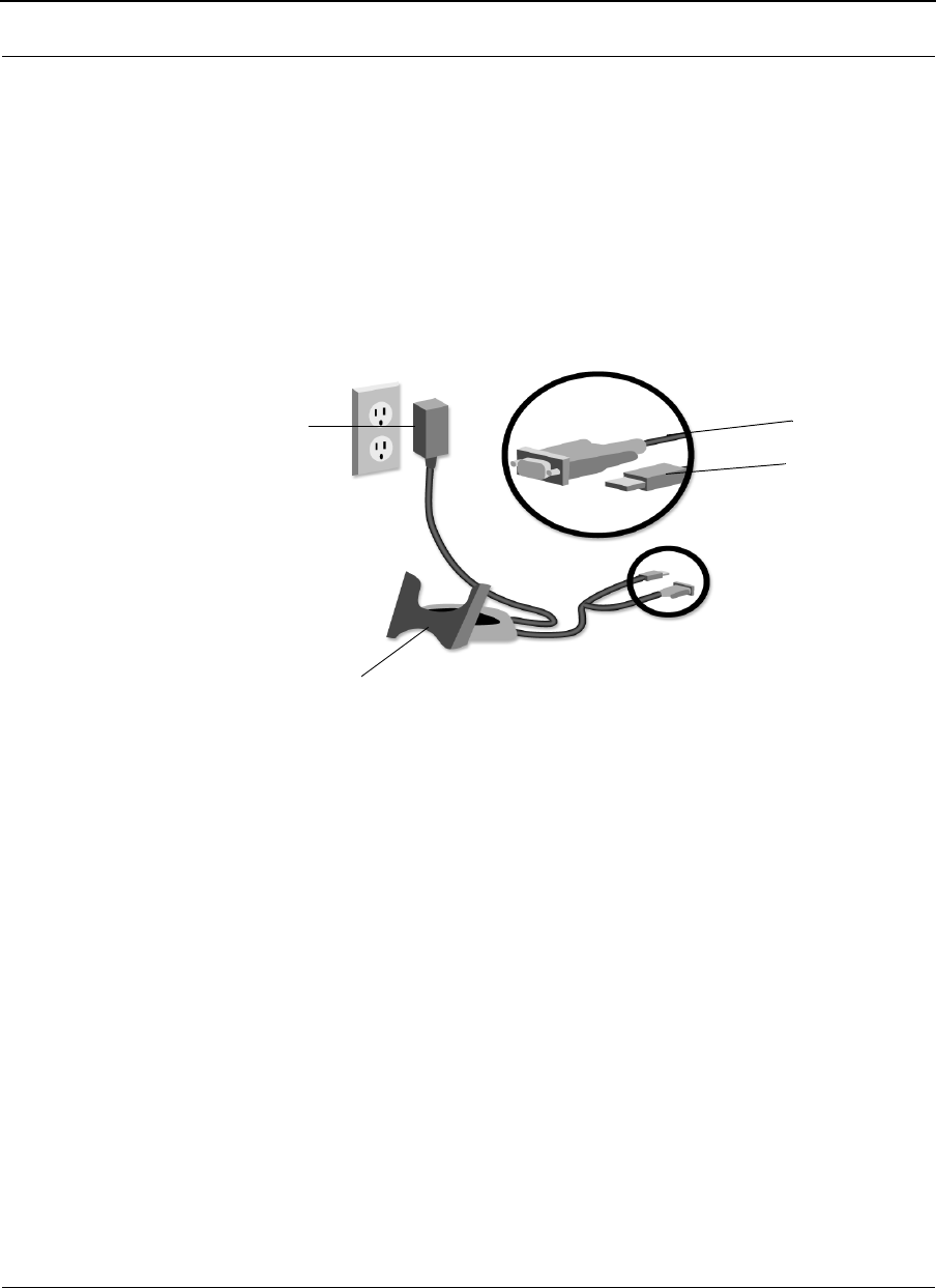
SPEEDLAN 9000 Series Installation and Operation User Guide Version 3.03
Appendix F (SPEEDSignal)-5
Installing the Compaq WL100 Wireless LAN PC Driver and ActiveSync
To install the wireless driver and ActiveSync, follow the directions below:
1Plug the AC Adapter into an outlet. Next, connect the AC adapter to the
Pocket PC PDA’s cradle. The serial or USB connector (not both) on the cradle
should be connected to the appropriate port on the front or back of your
desktop PC. On the desktop PC, start Active Sync. Insert the Pocket PC PDA
into the cradle. Refer to the installation diagram below to see how the
components should be connected.
Note: If you have not previously installed a USB device, you will be prompted
to install the USB device driver.
2Using ActiveSync, establish a connection between the Pocket PC PDA and the
desktop PC. (The Pocket PC PDA should now be in the cradle.)
Note: If you do not have ActiveSync, download it from this website: “http://
www.microsoft.com/mobile/pocketpc/downloads/”. Under Microsoft
Downloads, locate ActiveSync and download it. Note: It may take a few
minutes to download ActiveSync.
Follow the ActiveSync install prompts and instructions. ActiveSync will detect
the connection for the Pocket PC PDA. Continue to follow the onscreen
installation prompts to establish a connection between the Pocket PC PDA and
desktop PC. When you are prompted do establish a partnership, click No or
click Guest. For more information, refer to the Pocket PC PDA’s manual.
3If you WLAN driver does not support pseudo adhoc mode, you will need to
uninstall these drivers.
Plug AC Adapter
Cradle (Insert Pocket PC PDA into cradle)
USB to Desktop PC
Serial to Desktop PC
into wall outlet

Version 3.03 SPEEDLAN 9000 Series Installation and Operation User Guide
Appendix F (SPEEDSignal)-6
aTap Start+Settings+System tab+Remove Programs. Then, tap the
WLAN driver (i.e., Compaq WL100 Wireless LAN for...) and tap Remove.
Follow the onscreen instructions to remove the previous drivers.
(If prompted to remove the 802.11b Wireless LAN PC Card, remove it
now.)
4You will need a WLAN driver that will operate in psuedo adhoc mode.
In this example, we are downloading the WL100 PC radio card driver.
Download it to the desktop PC by following these steps:
aOpen your web browser. Go to: http://h18007.www1.hp.com/support/
files/handheldiPAQ/us/locate/48_1231.html.
bLocate the driver for the WL100 Wireless LAN PC Card, which is located
under the Network link. Download the driver and save it to a location on
your desktop PC. (Download this driver for Pocket PC PDA version 2002.)
5Install the driver on the Pocket PC PDA.
aEnsure that the Compaq WL100 PC Card is not inserted into the card slot
on the Pocket PC PDA.
bLocate the driver file on your desktop PC and double-click it.
cThe Microsoft Pocket PC PDA installation will begin automatically.
dFollow the installation instructions to install the drivers onto the Pocket PC
PDA. When the installation is complete, click Finish.
6Insert the WLAN PC Card into the Pocket PC PDA.
7If prompted for the device driver for the Pocket PC, type “WL100NDS.dll”.
Tap OK.
Tap the green "radio control" icon on the Windows taskbar of the
Pocket PC. (Make sure the 802.11b Wireless LAN PC Card is inserted in the
Pocket PC PDA.) The WLAN settings configuration utility will appear. Modify
the Pocket PC PDA’s WLAN settings to connect to the wireless network:
a Select Psuedo AdHoc for the Mode.
bSelect the appropriate AdHoc channel. (This will be the channel that you
are going to use to communicate with the wireless router.)

SPEEDLAN 9000 Series Installation and Operation User Guide Version 3.03
Appendix F (SPEEDSignal)-7
cTy pe "Any" for the SSID. Then, tap Apply to activate the modified WLAN
settings. Tap OK. You can verify that the above settings have been saved
by tapping the radio control icon on the Windows taskbar.
dYour WLAN PC Card is now ready to be used with SPEEDSignal. Your next
step is to install SPEEDSignal on the Pocket PC PDA. See the section
below.
Installing SPEEDSignal on the Pocket PC PDA
To install the SPEEDSignal application on the Pocket PC PDA, follow the directions
below:
1The Pocket PC PDA should now be in the cradle with the WLAN PC Card still in
it. A connection should now be established with ActiveSync.
2Locate the executable called SPEEDSignalPDA.exe. It will be in the following
directory on the CD: \SPEEDLAN 9000_Files\9000 Management Software\
SPEEDSignal PDA directory. (If the file is zipped,
double-click the zip file, which should be called SPEEDSignalPDA.zip. The
WinZip®dialog box will appear on your desktop PC, allowing you to extract it.
Select it and click the Extract button. Next, extract the executable to a location
on your computer, e.g., on your desktop PC).
3Click the Explore button on the ActiveSync dialog box (on the desktop PC).
4Copy the SPEEDSignalPDA.exe file to the “Mobile Device\My PocketPC\
Windows\Start Menu” directory.
5Check the Wave Wireless website for software updates. The SPEEDSignal for
PocketPC version will always be called "SPEEDSignalPDA.exe" to avoid
ambiguity between this version and SPEEDSignal for Desktop PC.
Enabling/Disabling SPEEDSignal (for Pocket PC PDAs)
Access for Wireless SPEEDSignal (choose the Support page under Admin menu of
SPEEDLAN 9000 Configurator)
This feature is used to enable or disable Pocket PC PDAs to communicate with
SPEEDSignal.
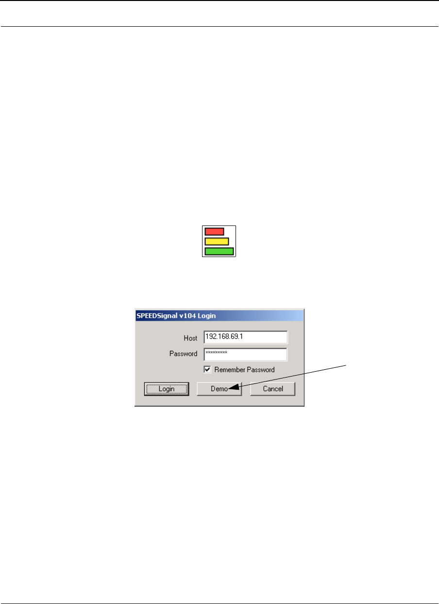
Version 3.03 SPEEDLAN 9000 Series Installation and Operation User Guide
Appendix F (SPEEDSignal)-8
•Click the Enabled option to enable communication with SPEEDSignal.
•Click Disabled to disable communication with SPEEDSignal. Click Apply
when finished.
Opening SPEEDSignal on the Desktop PC
To open SPEEDSignal on the desktop PC, follow these steps:
1To open SPEEDSignal on the desktop PC, double-click the SPEEDSignal
shortcut icon. Or, you can open SPEEDSignal from the Start menu by choosing
Programs+Wave Wireless+SPEEDSignal. If SPEEDSignal was installed in
another folder, select the appropriate directory.
SPEEDSignal shortcut icon
2When you open SPEEDSignal on the desktop PC, the SPEEDSignal Login
dialog box appears, as shown in the example below.
Login dialog box (desktop PC)
Enter the Node IP address (or hostname if you are using a Domain Server) of
the node you want to connect to in the Node IP Address text box.
The passwords are defined, based on user class level, in the SPEEDLAN 9000
Configurator. You need to enter the "Full Access" password as configured in
the SPEEDLAN Configurator. For more information, see Classes of Users (and
Passwords), page 3-10. Note: Also, if you want SPEEDSignal to recall the
password for future logins, click Remember Password. Click Login.
For demo mode only
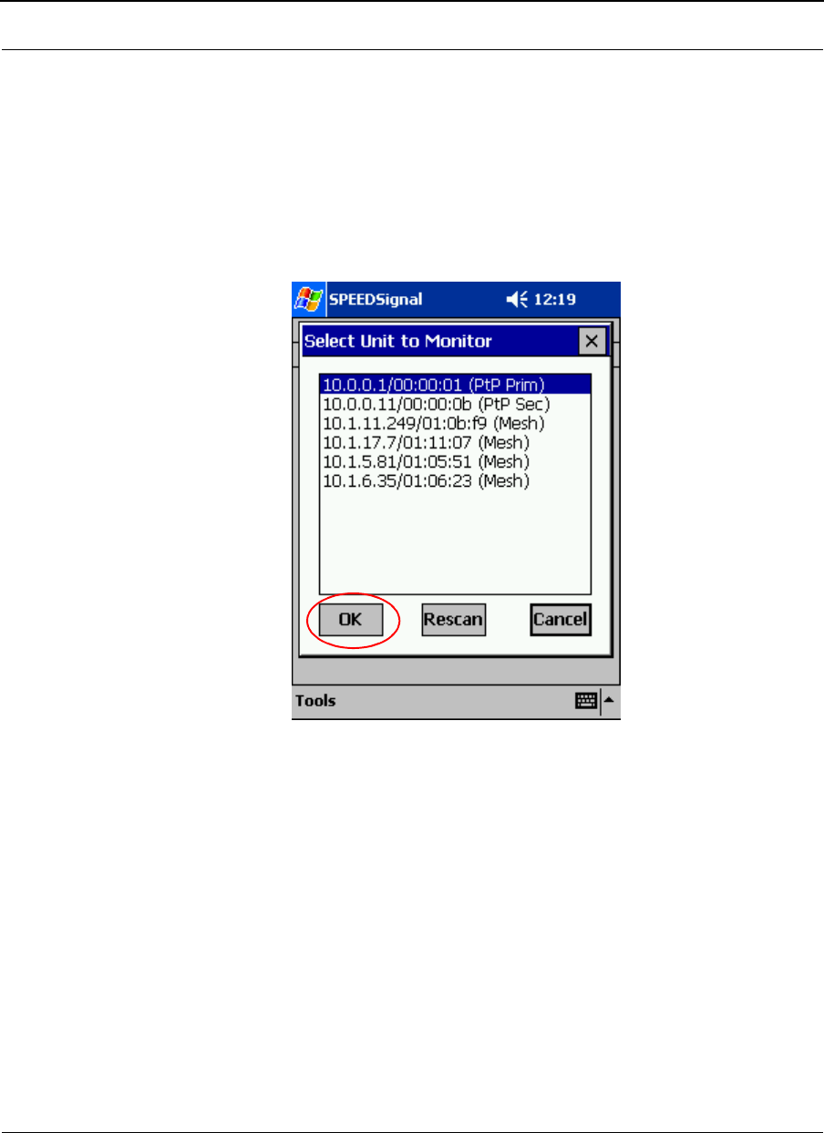
SPEEDLAN 9000 Series Installation and Operation User Guide Version 3.03
Appendix F (SPEEDSignal)-9
Opening SPEEDSignal on the Pocket PC PDA
To open SPEEDSignal on the Pocket PC PDA, follow these steps:
1Tap the Start button on the Windows taskbar. Then, tap Start+SPEEDSignal.
2The SPEEDSignal "Select Unit to Monitor" dialog box will appear (as shown in
the figure below). SPEEDSignal will scan for any SPEEDLAN 9000 routers
within range of the radio. Any units discovered will be listed. Then, select the
unit you want to monitor (as shown in the figure below).
Selecting a unit
3Next, click OK. Note: Click Rescan to monitor another 9000 router.
.
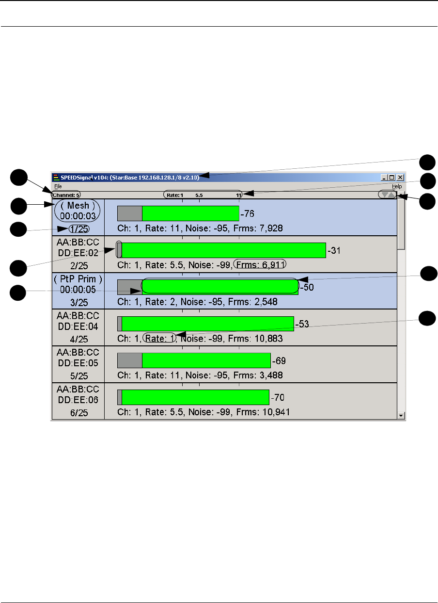
Version 3.03 SPEEDLAN 9000 Series Installation and Operation User Guide
Appendix F (SPEEDSignal)-10
SPEEDSignal’s Scanned Results
Note: The scanned results are very similar for both the Pocket PC PDA and desktop PC
versions of SPEEDSignal.
SPEEDSignal will report the following information for the router that is being monitored:
channel, MAC address, noise, signal and number of frames for each unit that the
monitored unit hears on the network. This information is recorded in separate rows, as
shown below.
Scanned results
Descriptions of scanned results:
A: Channel - Reports the channel of 802.11b incoming and outgoing
traffic. (This is abbreviated as "C" on the Pocket PC PDA).
B: MAC address and type of unit - Two items are included here: the MAC address of
the 802.11b unit SPEEDSignal hears on the network. It also lists the type of 9000 unit
(e.g., mesh, point-to-point, base station, CPE).
S
B
C
D
I
E
G
H
A
f
J
F
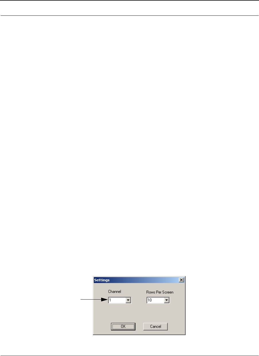
SPEEDLAN 9000 Series Installation and Operation User Guide Version 3.03
Appendix F (SPEEDSignal)-11
C: Row - Numeral value to represent each row of data (e.g., 2/25 means this is row 2
of the possible 25 rows. The maximum amount of rows is 25).
D: Noise - The noise represents the noise before the packets were received. This is
indicated in the gray area of the horizontal bar and it is expressed in dBm (e.g., -95).
(This is abbreviated as "Ns" on the Pocket PC PDA.)
E: Signal - This is the quality of the signal, which is displayed as red,
yellow or green. Red indicates a lack of signal strength, which means you cannot get a
reliable link at that rate. Yellow indicates a link at that rate is possible but not
recommended. Green indicates a link at a given rate should be attainable. (The signal
is expressed in dBm.)
F: Title bar: The horizontal blue bar at the top of the window that shows the name of
the 9000 unit (e.g., star: base station) and name of the program (SPEEDSignal).
G: Signaling Rate - 1, 5.5 or 11 Mb/s.
H: Up and down arrow - You can rearrange the order of the rows by highlighting a
row and clicking on the up or down arrow.
I: Frame - The total number of frames transmitted. (This is abbreviated as "Frm" on the
Pocket PC PDA.)
J - Rate (Signaling Rate) - Displayed as either 1, 2, 5.5 or 11 Mb/s. See also
description G (in the previous figure). (This is abbreviated as "Rx" on the Pocket PC
PDA.)
Adjusting SPEEDSignal Settings
Settings
If you want to change the settings, such as the channel and rows shown per screen,
choose Settings from the File menu. (For Pocket PC PDA, tap Tools and then tap
Settings. However, only the Channel setting will be available for the Pocket PC PDA.)
A dialog box similar to the following will appear:
Settings dialog box
This setting changes the channel on the
SPEEDLAN 9000, not the channel on the
SPEEDSignal unit being monitored.
Make sure that the channel on the
SPEEDLAN 9000 router and unit being
monitored match. If you want to change
the channel for your Pocket PC PDA’s, go
into the WLAN settings configuration utility.

Version 3.03 SPEEDLAN 9000 Series Installation and Operation User Guide
Appendix F (SPEEDSignal)-12
•Channel - This is the specific band of frequencies (from 1 to 11) to
determine the data path between routers. The following channels are
available:
12.412
22.417
32.422
42.427
52.432
62.437
72.442
82.447
92.452
10 2.457
11 2.462
•Rows Per Screen - You can select a value between 5 and 10. For example,
choosing 5 will magnify the rows (and display less rows) and choosing 10 will
do exactly the opposite (display more rows). (This feature does not appear for
the Pocket PC PDA version, only for the desktop PC version.)
Note about changing the channel:
•If you are using a wired network to connect to the remote SPEEDLAN 9000
unit: If you change the channel of the node you are connected to with
SPEEDSignal, the node will lose its connection to the network. For this reason,
you should only use SPEEDSignal while directly connected to a SPEEDLAN
9000 series router. If you are routed across the wireless network when you
change the channel of the router, you will lose your connection. You can do
this by establishing a direct connection to the remote node by:
•changing the channel in the (Channel drop-down list), or
•power cycle the remote node (shut down node and turn it back on again).
•For wireless connections: If you change the channel of the 9000, you must
change the Pocket PC PDA to the corresponding channel to resume wireless
communications.
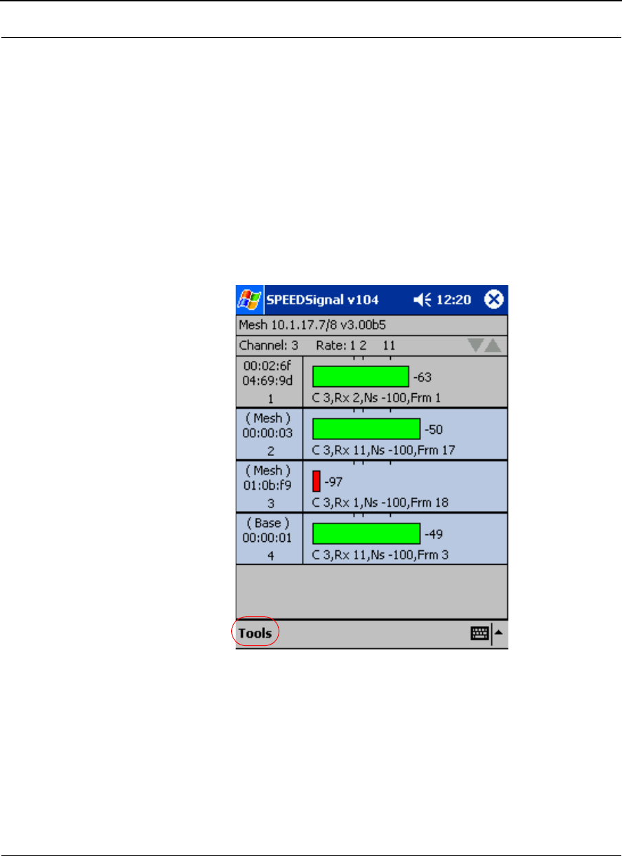
SPEEDLAN 9000 Series Installation and Operation User Guide Version 3.03
Appendix F (SPEEDSignal)-13
Clear List
For the desktop PC version, if you choose Clear List from the File menu, all of the rows
will be removed from the frame list. For the Pocket PC PDA version, tap Tools and then
Clear List. When you switch channels the frames seen on the previous channel remain
unless you choose Clear List.
How To Exit SPEEDSignal on the Pocket PC PDA
Make sure the application is open that you want to exit. Tap the Tools menu located on
the bottom left hand corner of the screen (as circled below). Then, tap Exit.

Version 3.03 SPEEDLAN 9000 Series Installation and Operation User Guide
Appendix F (SPEEDSignal)-14
Troubleshooting
Read this section to troubleshoot any problems when using SPEEDSignal for Pocket PC
PDA.
•Unit is not displayed in Scan dialog box of Pocket PC PDA - If the unit you want
to monitor is not listed among the scanned results, try tapping Rescan again,
or move closer to the radio if needed (see next bullet).
•Radio is out of range - Depending on the antennas involved, you may need to
minimize your distance from the 9000 router that is being monitored. When
using directional antennas, make sure there is line of sight between the units to
establish communication.
•SPEEDSignal is disabled on the Pocket PC PDA - As shipped, SPEEDSignal
can communicate with a wired (via desktop PC) or wireless interface
(via Pocket PC PDA). Your network administrator may have disabled
SPEEDSignal for the Pocket PC PDA for security reasons.
•How do I modify the radio card settings (Mode and Channel)? Make sure your
802.11b Wireless LAN PC Card is inserted. You will see a green radio control
icon on the lower right hand corner of your screen. Tap this and you will be
able to modify your Mode and Channel settings.
If you want to enable SPEEDSignal for the Pocket PC PDA, ask your network
administrator to re-enable it through the SPEEDLAN 9000 Configurator. This will re-
establish communication between the 9000 wireless router and embedded unit.
Special Copyright Information Regarding Compaq and Microsoft®: Compaq and the
Compaq logo are registered in the U.S. Patent and Trademark Office. iPAQ is a
trademark of Compaq Information Technologies Group. Microsoft and ActiveSync and
any references to Windows are either registered trademarks or trademarks of Microsoft
Corporation.

SPEEDLAN 9000 Series Installation and Operation User Guide Version 3.03
Product License Agreement
It is important for users of Wave Wireless hardware and software to take time to read this License Agreement
associated with this software PRIOR TO ITS USE. The Customer or Reseller has paid a License fee to Wave
Wireless for use of this software on one router. This License does not extend to any copyrights to the program
nor does it license use of the program on more than one router nor to make copies of the program for
distribution or resale. A product registration card is included with the product manual. Please complete the
card within 10 days of receipt of the software/hardware and return it to Wave Wireless. Registration is
required for warranty service, technical support and notification of product updates and revisions.
The Customer or Reseller is granted a non-exclusive License to use the licensed program on a single router
subject to the terms and conditions as set forth in this agreement. The Customer or Reseller may not copy,
modify or transfer the reference manual or other documentation or any copy thereof except as expressly
provided in this agreement.
The Copyright and all intellectual/industrial rights of this program and associated material remain the
property of Wave Wireless. THE CUSTOMER OR RESELLER MAY NOT USE, COPY, SUBLICENSE,
ASSIGN OR TRANSFER THE LICENSED MATERIALS OR ANY COPIES THEREOF IN WHOLE OR IN
PART, EXCEPT AS EXPRESSLY PROVIDED IN THIS LICENSE AGREEMENT. The Customer or Reseller shall
not reverse assemble or reverse compile the Licensed product or any copy thereof in whole or in part.
Software License Agreement
The installation and use of this SOFTWARE indicates your understanding and acceptance of the following
terms and conditions. This license shall supersede any verbal or prior written, statement or agreement to the
contrary. If you do not understand or accept these terms, or your local regulations prohibit “after sale” license
agreements or limited disclaimers, you must cease and desist using this product immediately.
The following terms govern your use of the enclosed Software:
License Grant
Wave Wireless Networking (hereafter referred to as Wave) grants you a license to Use one copy of the
Software on one single-user PC, notebook, or laptop computer. It may not be installed on multiple devices
and may not be shared by more than one individual while in use on a single device. “Use” means storing,
loading, installing, executing or displaying the Software. You may not modify the Software or disable any
licensing or control features of the Software. Uses of this software other than those expressly defined herein
are forbidden. Wave does not provide support for, nor will it accept return of, this Software if it is used in any
manner other than those outlined here.

Version 3.03 SPEEDLAN 9000 Series Installation and Operation User Guide
Ownership
The Software is owned and copyrighted by Wave or its third party suppliers. Your license confers no title or
ownership in the Software and is not a sale of any rights, other than the limited right of Use defined above, in
the Software. Wave and Wave’s third party suppliers may protect their rights in the event of any violation of
these License Terms.
Copies and Adaptations
You may only make copies or adaptations of the Software for archival purposes or when copying or
adaptation is an essential step in the authorized Use of the Software. You must reproduce all copyright
notices in the original Software on all copies or adaptations. You may not copy the Software onto any bulletin
board or similar system.
No Disassembly or Decryption
You may not disassemble or decompile the Software unless Wave’s express prior written consent is obtained
except in those jurisdictions where Wave’s consent is not required for disassembly or decompilation. Upon
request, you will provide Wave with reasonably detailed information regarding any disassembly or
decompilation. You may not decrypt the Software for any reason.
Transfer
Your license will automatically terminate upon any transfer of the Software or equipment containing the
Software. Upon transfer, you must deliver the Software, including any copies and related documentation, to
the transferee. The transferee must accept these License Terms as a condition to the transfer.
Terminatio n
Wave may terminate your license upon notice for failure to comply with any of these License Terms. Upon
termination, you must immediately destroy the Software, together with all copies, adaptations and merged
portions in any form.
Export Restriction
You agree that you will not export or re-export the PRODUCT in any form without the appropriate
government licenses. Your failure to comply with this provision is a material breach of this AGREEMENT.
U.S. Government Restricted Rights
The Software and documentation have been developed entirely at private expense and are provided as
“Commercial Computer Software” or “restricted computer software”. They are delivered and licensed as
“commercial computer software” as defined in DFARS 252.227-7013 (Oct 1988), DFARS 252.211-7015
(May 1991) or DFARS 252.227-7014 (Jun 1995), as a “commercial item” as defined in FAR 2.101 (a), or as
“Restricted computer software” as defined in FAR 52.227-19 (Jun 1987) (or any equivalent agency
regulation or contract clause), whichever is applicable. You have only those rights provided for such Software
and Documentation by the applicable FAR or DFARS clause or the Wave standard software agreement for the
product.

SPEEDLAN 9000 Series Installation and Operation User Guide Version 3.03
WAVE WIRELESS NETWORKING LIMITED WARRANTY STATEMENT
1.Wave warrants to you, the end-user customer, that Wave hardware, software, accessories and supplies, will
be free from material defects in materials and workmanship for one year after the date of purchase. If Wave
receives notice of such defects during the warranty period, Wave will, at its option, either repair or replace
products which prove to be defective.
2. Wave does not warrant that the operation of Wave products will be uninterrupted or error free. Wave
products may contain remanufactured parts equivalent to new in performance or may have been subject to
incidental use.
3. The limited Warranty does not apply to defects resulting from (a) improper or inadequate maintenance or
calibration, (b) software, interfacing, parts or supplies not supplied by Wave, (c) unauthorized specifications
for the product, or (d) improper site preparation or maintenance.
4. ANY IMPLIED WARRANTY OF MERCHANTABILITY OR FITNESS FOR A PARTICULAR PURPOSE IS LIMITED
TO THE DURATION OF THE EXPRESS WARRANTY SET FORTH ABOVE. Some states or provinces do not
allow limitations on the duration of an implied warranty, so the above limitation or exclusion might not apply
to you. This warranty gives you specific legal rights and you might also have other rights that vary from state
to state, or province to province.
5. THE REMEDIES IN THIS WARRANTY STATEMENT ARE YOUR SOLE AND EXCLUSIVE REMEDIES. EXCEPT
AS INDICATED ABOVE, IN NO EVENT WILL Wave BE LIABLE FOR LOSS OF DATA OR FOR DIRECT,
SPECIAL, INCIDENTAL, CONSEQUENTIAL (INCLUDING LOST PROFIT), OR OTHER DAMAGE, WHETHER
BASED IN CONTRACT, TORT, OR OTHERWISE. Some states or provinces do not allow the exclusion or
limitation of incidental or consequential damages, so the above limitation or exclusion may not apply to you.

Version 3.03 SPEEDLAN 9000 Series Installation and Operation User Guide
Return Policies and Warranties
Initial One Year Warranty Term
Each Wave Wireless product is warranted against defects in material and workmanship for a period of one
year from date of shipment. During the warranty period Wave Wireless will, at its option, repair or replace
products that prove to be defective.
If equipment fails, the Customer or Reseller shall notify Wave Wireless and request a Return Material
Authorization (RMA) number. For warranty service or repair, this product must be returned to Wave Wireless.
All returns to Wave Wireless MUST have a valid RMA number written clearly on the outside of the
box or the shipment will be refused. The buyer shall pay all return shipping charges during the
one-year warranty.
Return for Credit
All returns to Wave Wireless MUST have a valid RMA number written clearly on the outside of the
box or the shipment will be refused. No returns for credit after 30 days will be approved. Products must
be returned undamaged and in original packaging or they will be subject to a minimum 20% restocking/
refurbishing fee. Return freight charges must be prepaid. At the option of Wave Wireless, products may be
returned for repair or replaced provided the goods have not been modified or repair attempted by someone
other than Wave Wireless.
Limitation of Warranty
The foregoing warranty shall not apply to defects resulting from improper or inadequate maintenance by the
buyer, buyer supplied interfacing, unauthorized modification or misuse, operation outside of the
environmental specifications for the product, or improper site preparation or maintenance. Systems must be
protected from electrical brownouts and surges by a quality UPS such as an APC Smart brand or
Tripp Lite Omni or similar, or warranty shall be null and void. Warranties do not apply to any product
that has been (i) altered, except expressly approved by Wave Wireless in accordance with its instructions, (ii)
damaged by improper electrical power or environment, abuse, misuse, accident, or negligence. Repairs in
the case of damage from "acts of God" are covered on a time and materials basis.
THE FOREGOING WARRANTIES ARE EXCLUSIVE REMEDIES AND ARE IN LIEU OF ALL OTHER
WARRANTIES, EXPRESS OR IMPLIED, INCLUDING, WITHOUT LIMITATION, ANY WARRANTY OF
MERCHANTABILITY OR FITNESS FOR A PARTICULAR PURPOSE.
No statement, including, without limitation, representations regarding capacity, suitability for use or
performance of products, whether made by Wave Wireless employees or otherwise, shall be deemed to be a
warranty by Wave Wireless for any purpose or give rise to any liability for Wave Wireless unless expressly
contained in writing. Resellers will have complete responsibility and liability for performance of its agreements
with its customers and Resellers shall indemnify and hold Wave Wireless harmless from and against all
liability arising out of such agreements.

SPEEDLAN 9000 Series Installation and Operation User Guide Version 3.03
Wave Wireless warrants that the firmware for use with the unit will execute its programming instructions when
properly installed on the unit. Wave Wireless does not warrant that the operation of the unit or firmware will
be uninterrupted or error-free. Wave Wireless shall not be obligated to remedy any software defect that
cannot be repeated.
Wave Wireless is not responsible for equipment non-performance due to outside radio interference caused by
any source.
Exclusive Remedies
The remedies provided herein are the buyer's sole and exclusive remedies. Wave Wireless shall not be liable
for any direct, indirect, special, incidental or consequential damages, whether based on contract, tort or any
legal theory.

Version 3.03 SPEEDLAN 9000 Series Installation and Operation User Guide
Notes:_____________________________________________
__________________________________________________
__________________________________________________
__________________________________________________
__________________________________________________
__________________________________________________
__________________________________________________
__________________________________________________
__________________________________________________
__________________________________________________
__________________________________________________
__________________________________________________
__________________________________________________
__________________________________________________
__________________________________________________
__________________________________________________
__________________________________________________
__________________________________________________
__________________________________________________
__________________________________________________
__________________________________________________
__________________________________________________
__________________________________________________

SPEEDLAN 9000 Series Installation and Operation User Guide Version 3.03
Index-1
Index
A
Address Sharing 3-6
Factory reset 3-77
Permissions 3-74
Software update 3-76
User configuration 3-74
C
Configuring in base station mode
Authentication 4-43
Configuring data and channel rate 4-7
Encryption 4-8
Interfaces 4-2
Remotely controlling 4-15
Star timing parameters 4-7
Updating the software 4-16
Configuring in CPE mode 5-1
Configuring in mesh mode 7-1
Configuring in point-to-point mode 6-1
Configuration menu 3-7
DHCP Server menu 33-9
Loggin On 3-10
Network menu 3-20
Routing menu 3-31
Security alert 3-13
System menu 3-25
D
Desktop PC Appendix F-2
DHCP Relay menu 3-47
DHCP Server menu
Basic Instructions for Setting UP DHCP on an Interface 3-40
General clients 3-44
Known clients 3-46
Diagnostics
IP Recovery Appendix B-1
SPEEDView
Performing a bandwidth test 9-14
Performing a ping test 9-15
Diagnostics menu 3-67
ARP table 3-70
ICMP 3-71
Interface statistics 3-68

Version 3.03 SPEEDLAN 9000 Series Installation and Operation User Guide
Index-2
E
Equipment (9000) features 1-5
F
Features 1-2
9101 1-5
9102 1-5, 1-3
9103 1-5, 1-3
9104 1-5
Firewall 3-61
Forwarding menu 3-48
Forwarding menu,3- 1
1 NAT 3-60
Forwarding menu, Address sharing 3-56
Firewall 3-61
General NAT info 3-54
Internal servers 3-58
Services 3-49
H
Hardware 2-5, 2-3
9101 (Mesh) 2-5
9104 (Mesh) 2-6
Base 2-13, 2-14
Bottom view of star unit 2-15
CPE 2-12
Indoor junction box 2-4
I
Setting up data and channel rate in base mode 4-10
Installation Steps
Installation Diagram 2-22
Installation Steps for Star 2-16
Internal Servers 3-58
IP Recovery Appendix B-2
installing & requirements Appendix B-2
Setting a temporary address Appendix B-5
Transmit power test Appendix B-6
IP Sessions 3-66
ISP 1-3
M
Manual Configuration 3-2
Mesh topology 1-8
N
NAPT 3-60
NAT 3-56

SPEEDLAN 9000 Series Installation and Operation User Guide Version 3.03
Index-3
Network management 1-3
Network menu
TCP/IP 3-20
P
Polling 1-6
R
Router
Base Station 4-1
Changing the router’s topology mode Appendix A-1
Common functionality 3-1
CPE mode 5-1
Mesh mode 7-1
Point-to-point mode 6-1
Routing menu
Default gateway 3-32
Route table 3-36
Static route 3-37
S
SPEEDSignal Appendix F-2,
Desktop PC version Appendix F-2
Enabling and disabling Wireless SPEEDSignal Appendix F-7
Exiting the application Appendix F-13
Opening SPEEDSignal Appendix F-9
PocketPC version Appendix F-4
Settings Appendix F-2
Scanned results Appendix F-10
Troubleshooting Appendix F-14
SPEEDView 8-1
Accessing the statistics on the Main tab 8-16
Admin tab 8-4
Combined tab 8-17
Downstream tab 8-16, 8-17
Installation instructions 8-2, 8-3
Main tab 8-8
Node, Link, Stats and View 8-11
Options tab 8-2
Program instructions 8-8
Star network 8-6
Stats Setup tab 8-18
System Requirements 8-2
TCP Dump tab 8-19
TCP Setup tab 8-20
Upstream tab 8-17
What is it? 8-1

Version 3.03 SPEEDLAN 9000 Series Installation and Operation User Guide
Index-4
Star Topology 1-6
Network expansion 1-12
Point-to-multipoint 1-6
point-to-point 1-6, 1-8
System menu
Host name 3-29
Password 3-30
Reboot 3-31
Version 3-29
System requirements 3-4
V
Virtual Addresses 3-24