Wave Wireless Networking SLSC5800 Point to Point Spread Spectrum Transceiver User Manual Manual
Wave Wireless Networking Point to Point Spread Spectrum Transceiver Manual
UserManual.wiki
>
Wave Wireless Networking
>
SLSC5800 User Manual
Manual
Navigation menu
Upload a User Manual
Namespaces
Wiki Guide
HTML
PDF
Info
Views
User Manual
Discussion / Help
Navigation
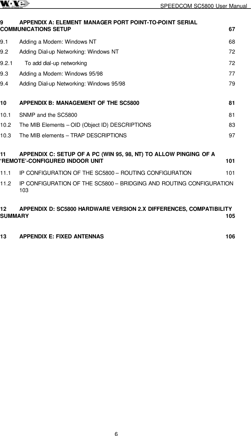

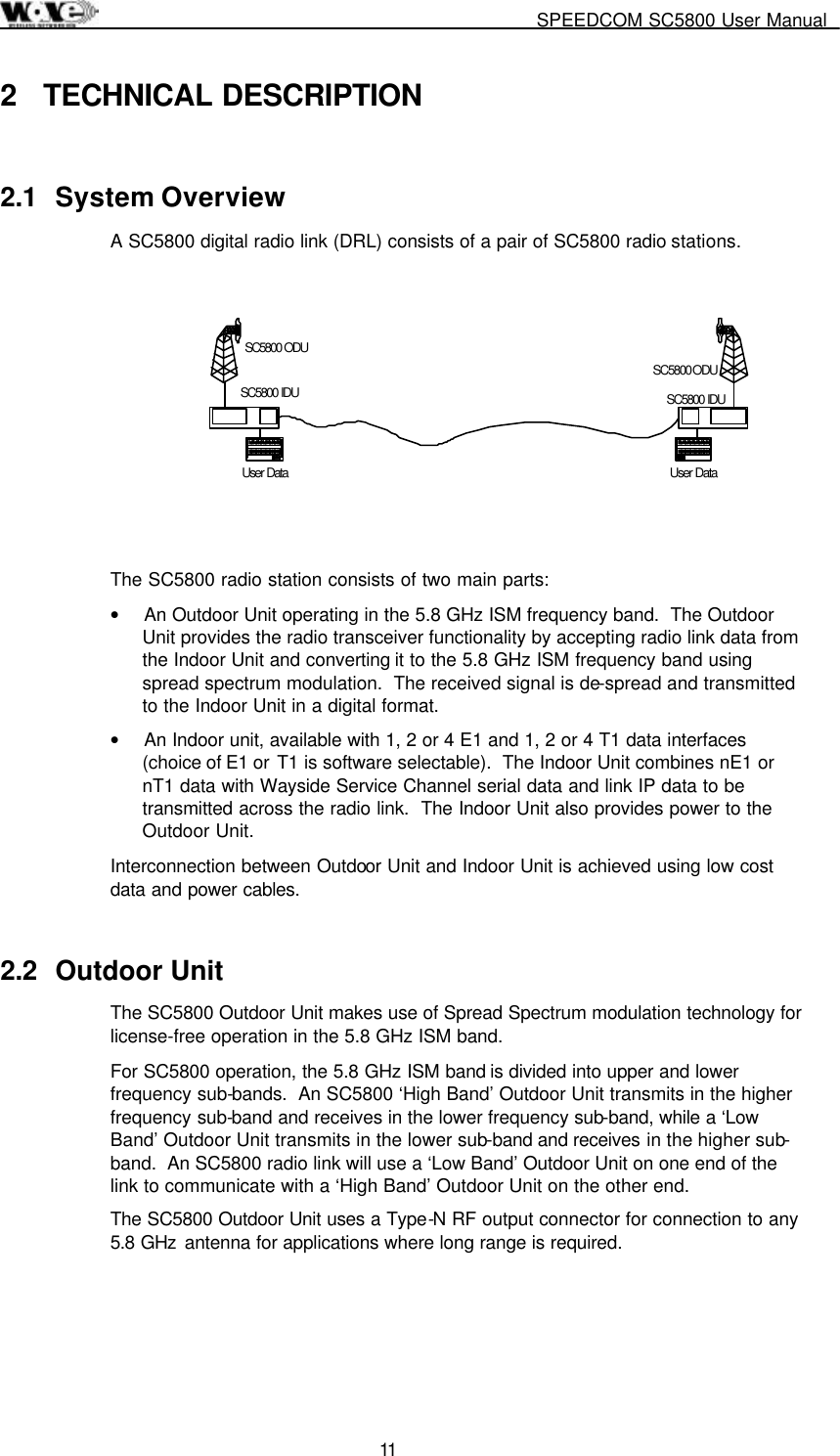
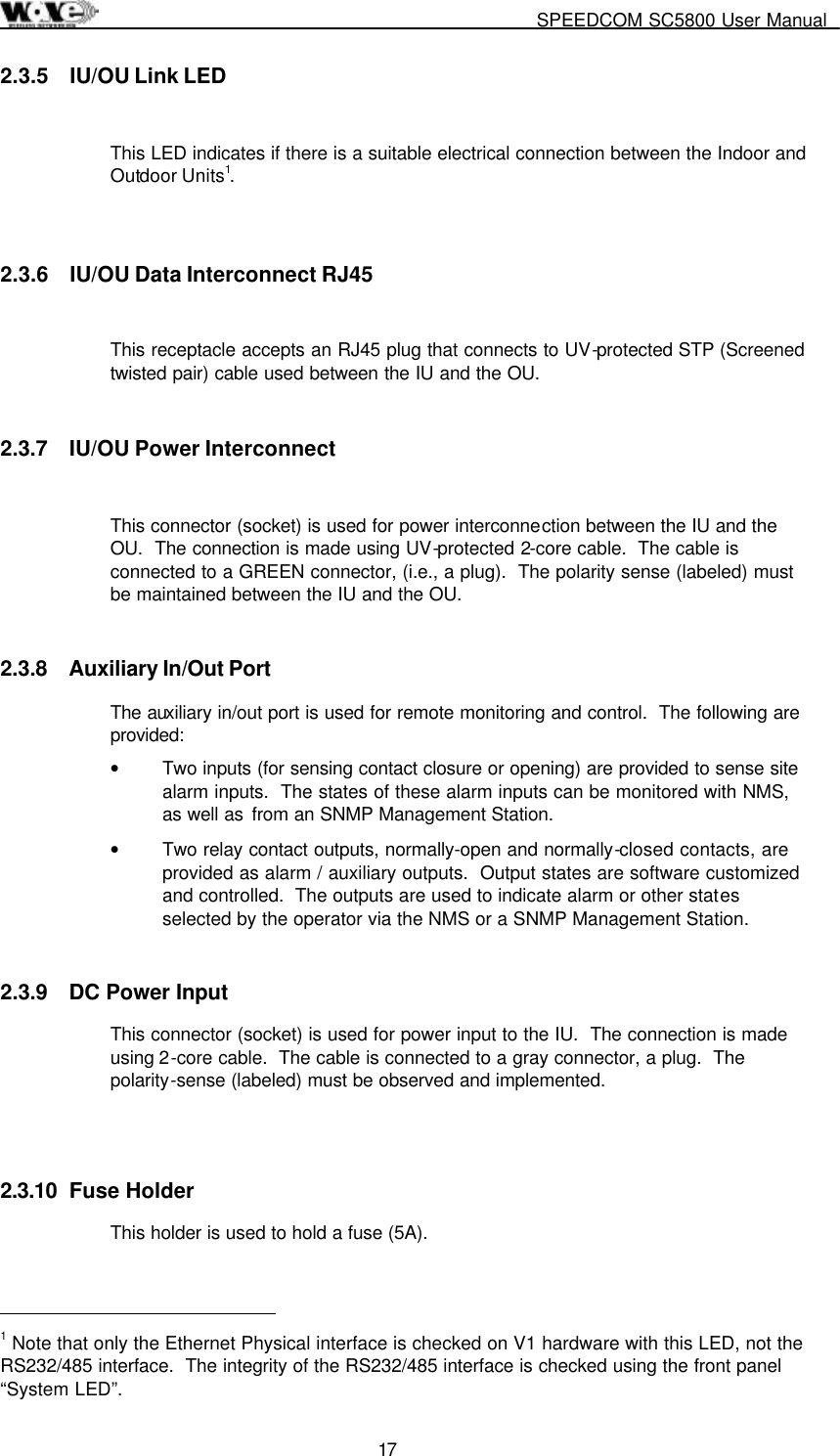
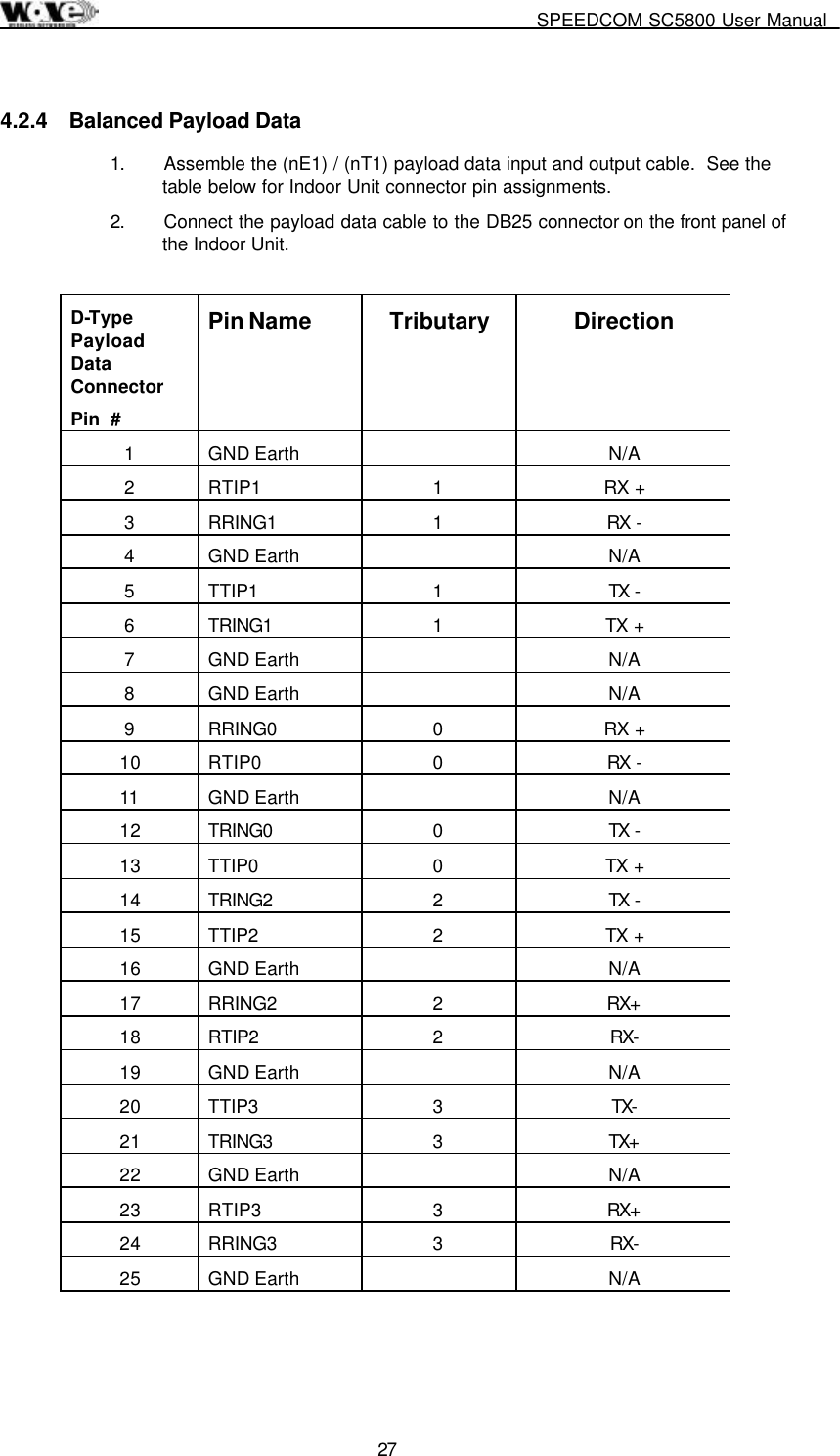
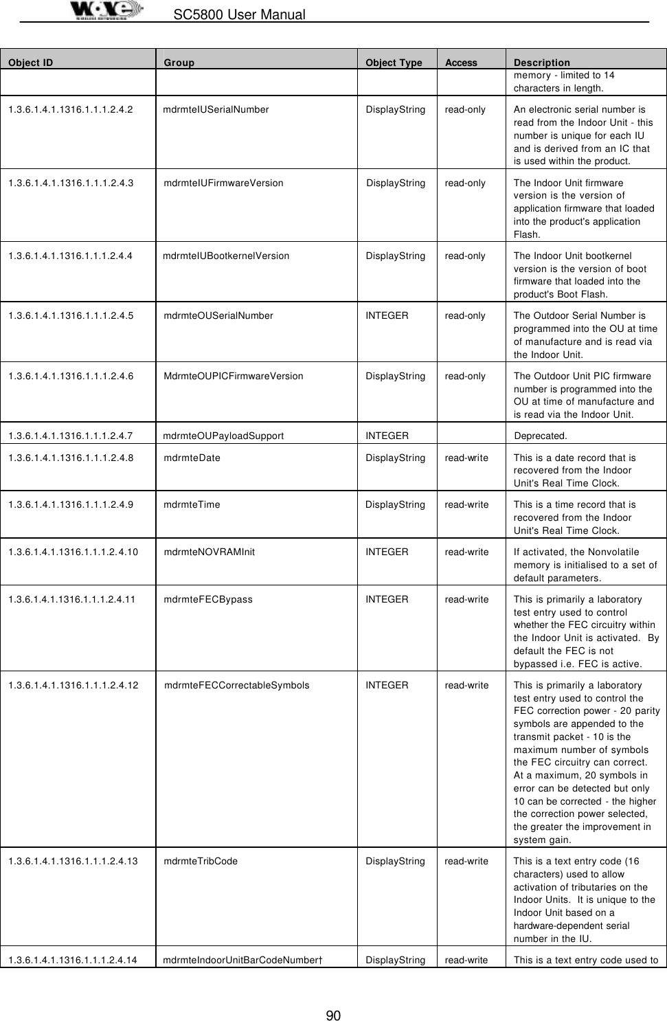
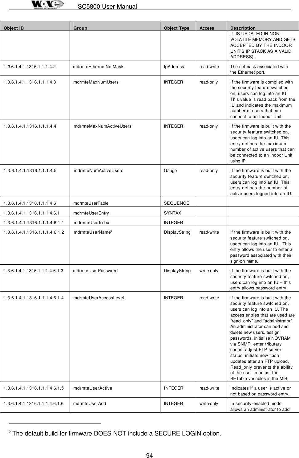
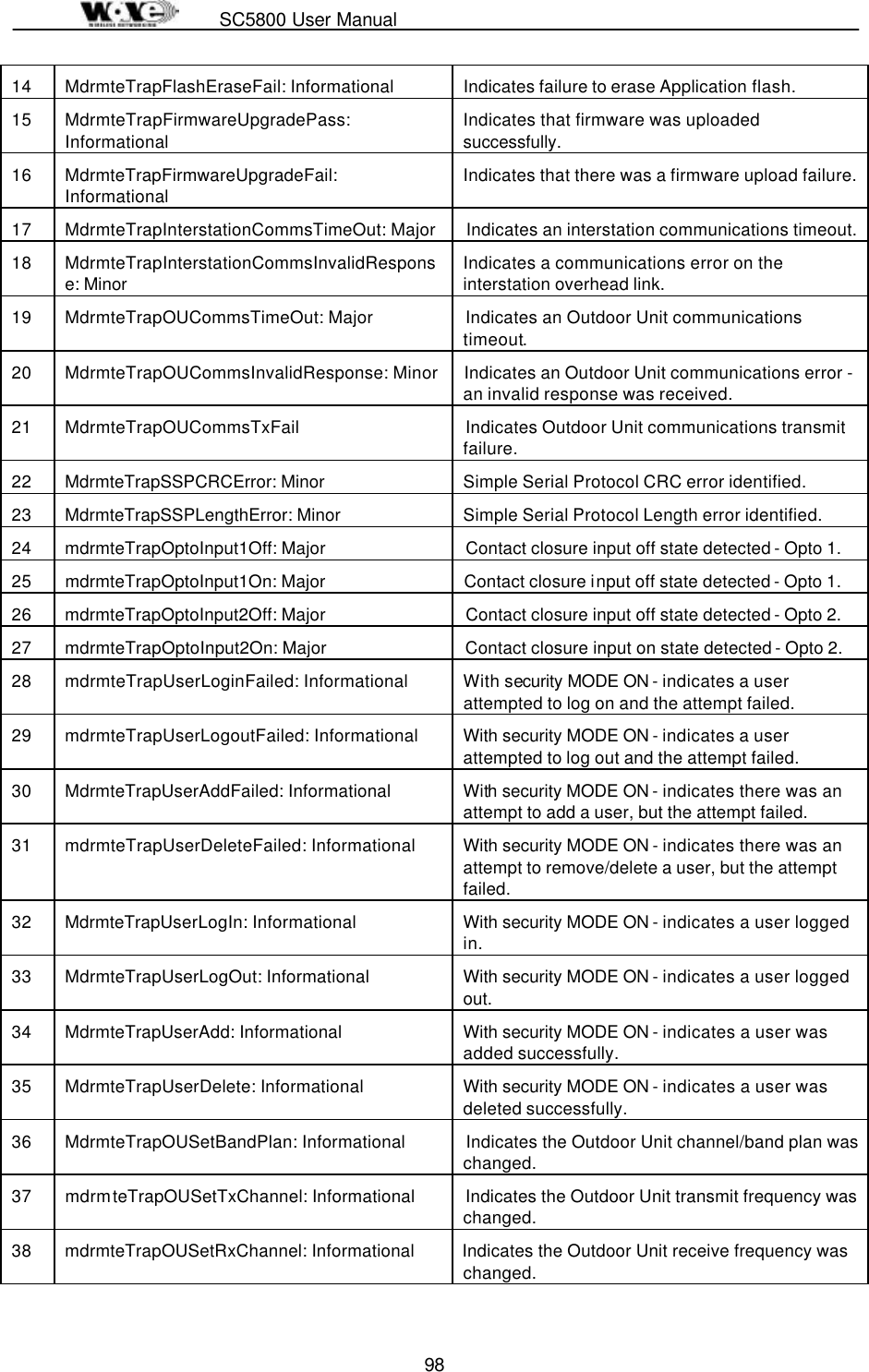
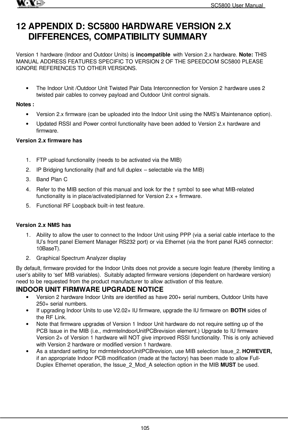
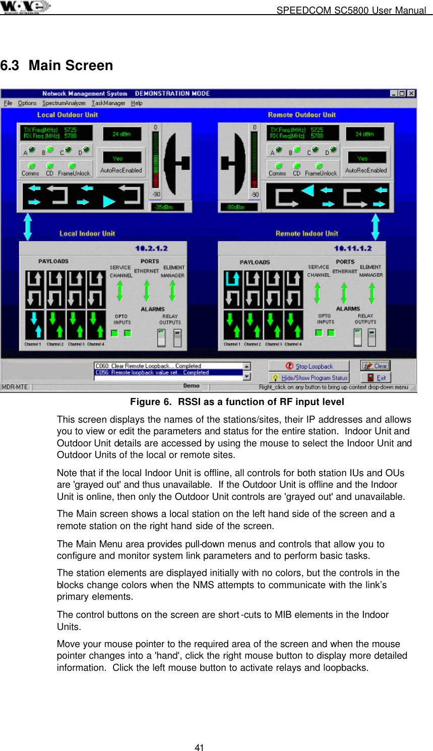
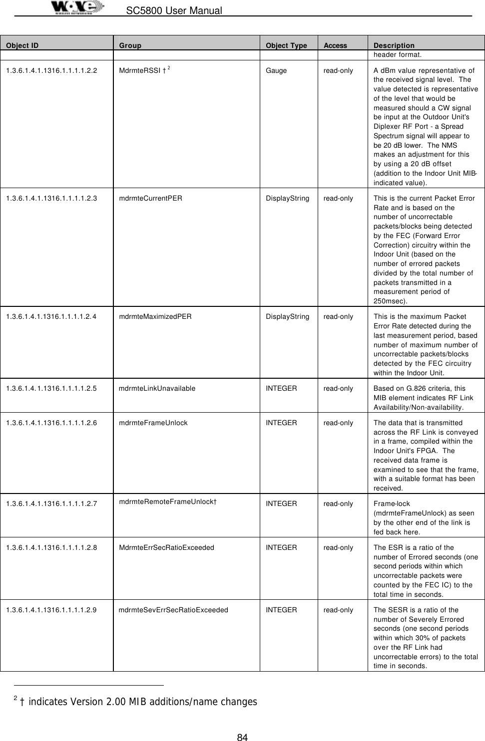
![SPEEDCOM SC5800 User Manual 37 5.7 SC5800 Test Record Parameter Unit Site A Site B Frequency channel plan: Transmit Receive A/B/C/D A/B/C/D If D – List Transmit and Receive Frequencies [MHz] Transmitter output power dBm Receiver input level (ON) Volts Receiver input level (ON) dBm Receiver input level (OFF) Volts Receiver input level (OFF) dBm Calculated input level dBm Fade margin dB Frame Lock indicator Color Fixed attenuator dB BER-test Hours BER Alarm Indicators Clear (Yes/No) Date Name Signature Performed by Approved by](https://usermanual.wiki/Wave-Wireless-Networking/SLSC5800/User-Guide-172242-Page-39.png)

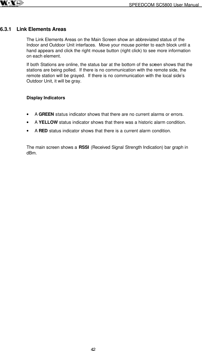


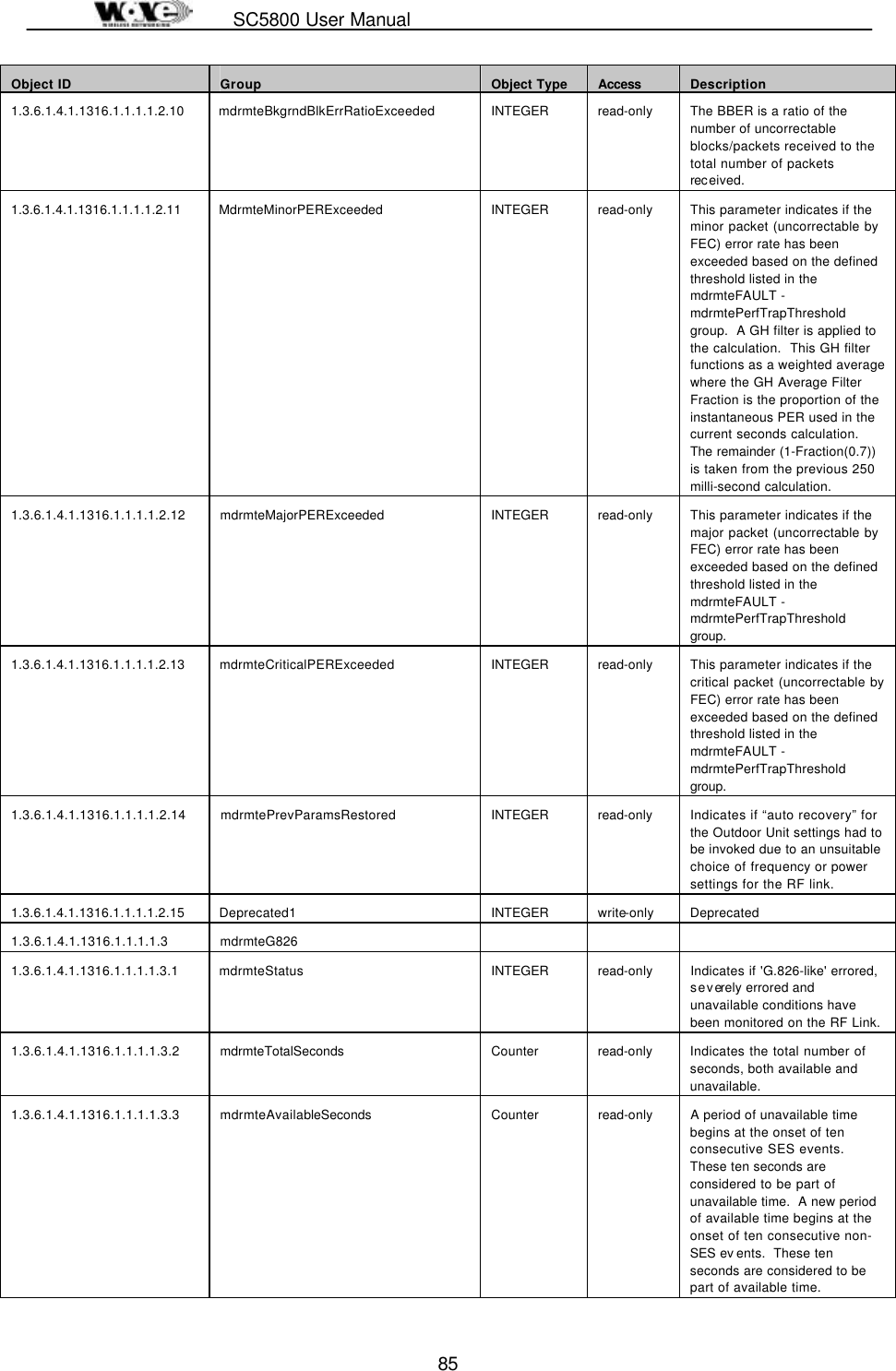
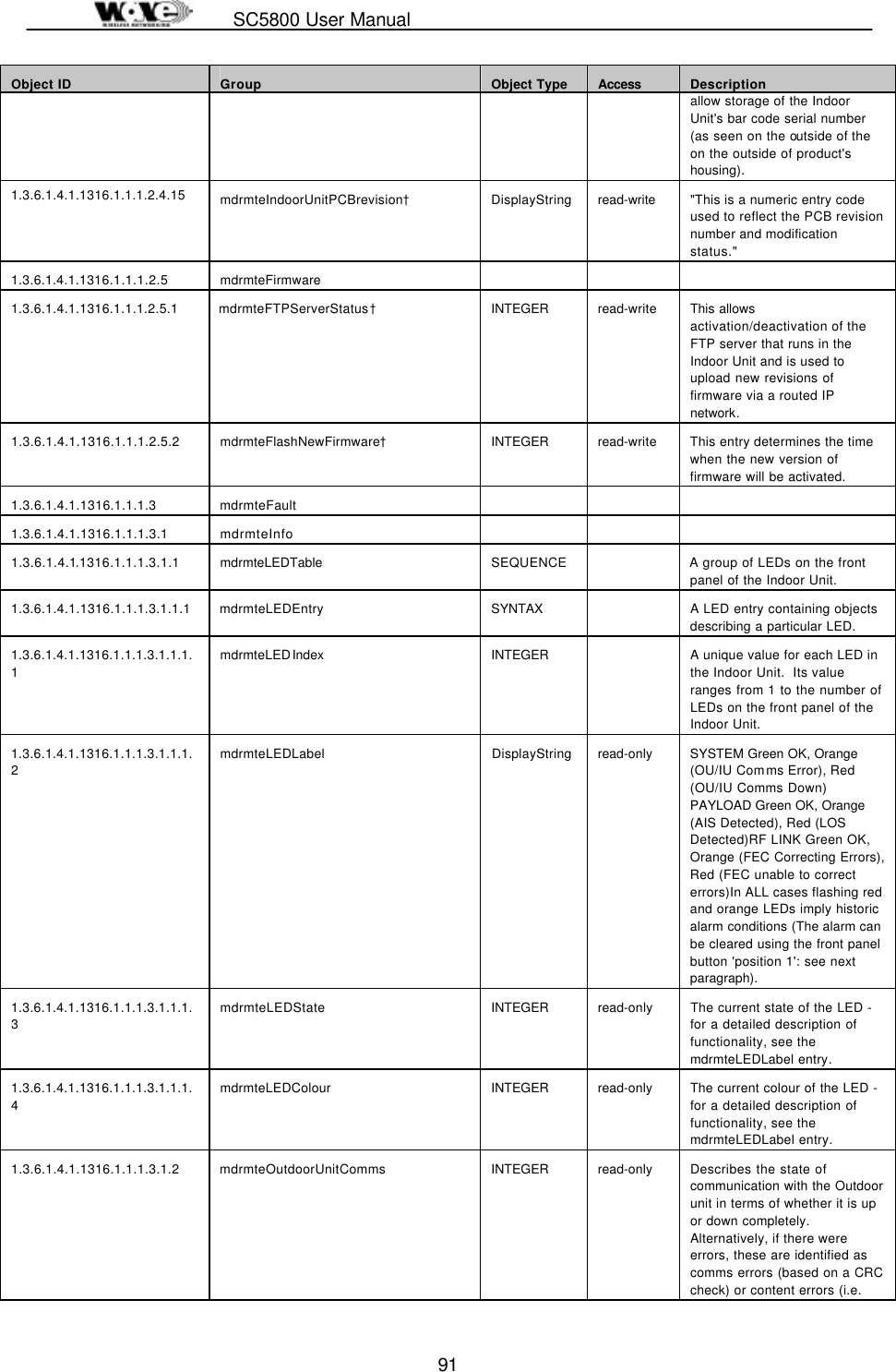
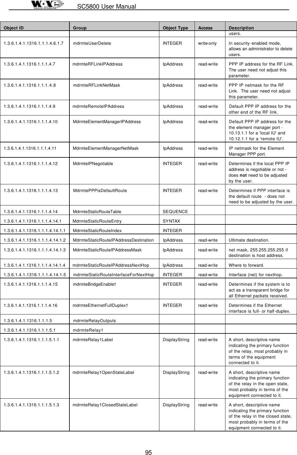
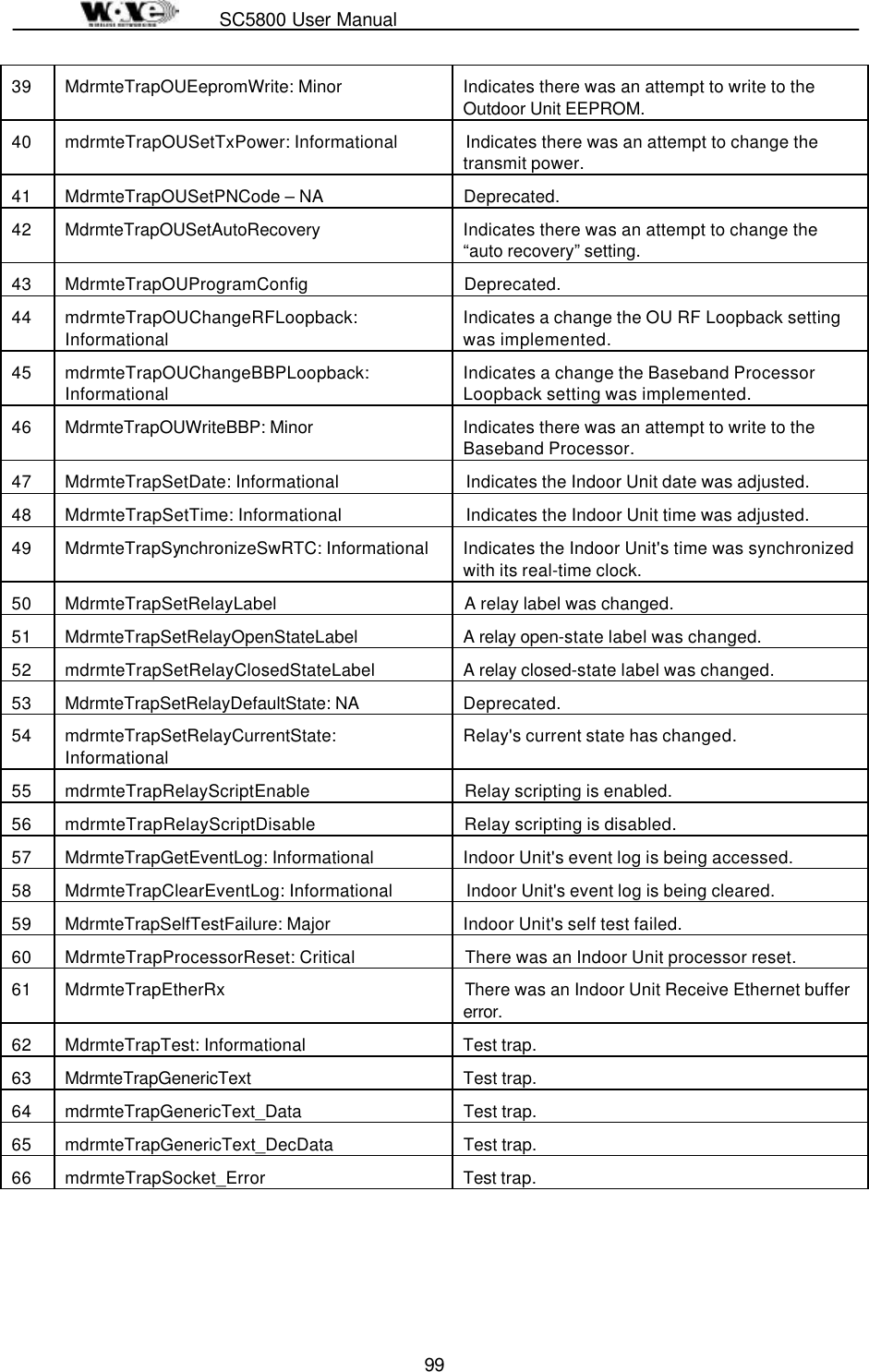
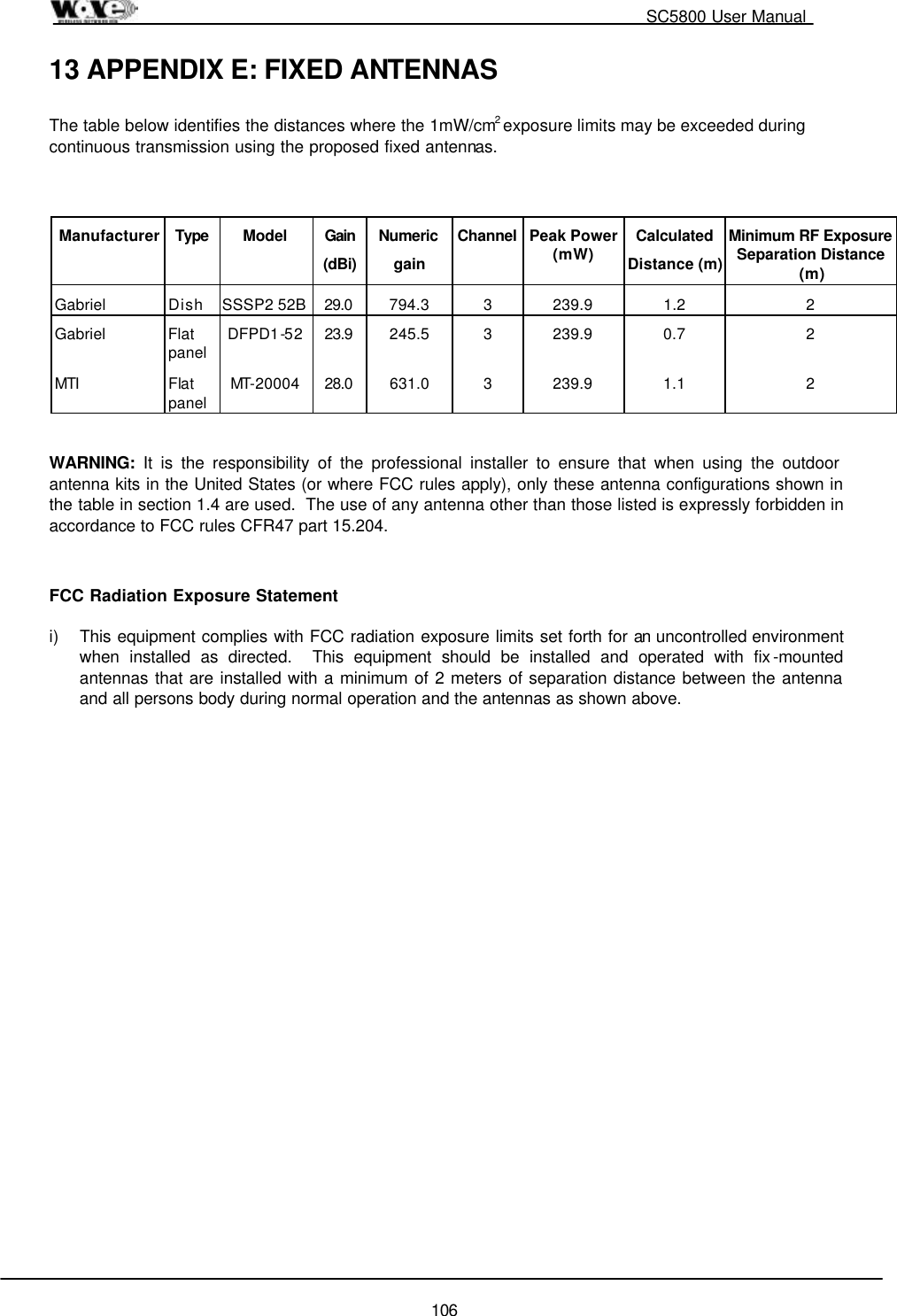
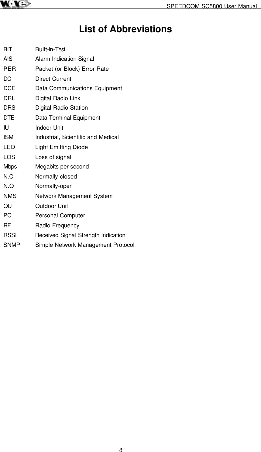
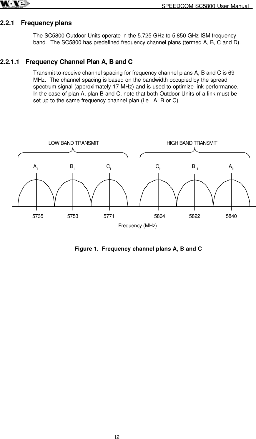
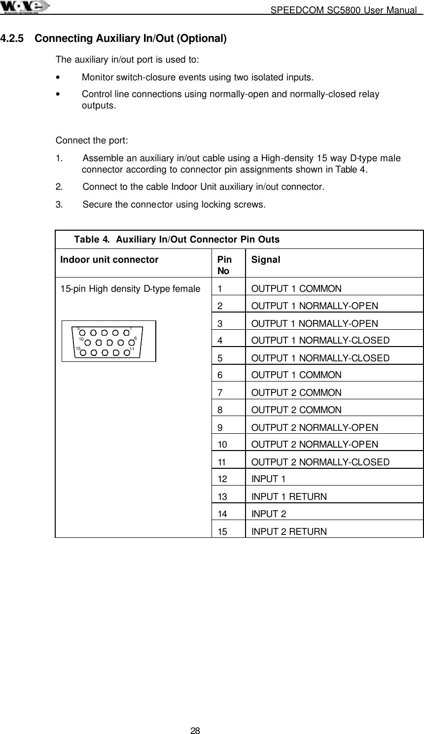
![SC5800 User Manual 88 Object ID Group Object Type Access Description degradation can be expected when operating using channel plan D mode and the chosen frequencies are close to the sub-band edges i.e. a choice of one of the high frequencies in the lower sub-band and one of the lower frequencies in the upper sub-band. The allocation of Channel plan D frequencies is Lower Sub-band - 5735-5771 MHz, Upper Sub-band - 5804-5840 MHz. The user must take note of whether the radio is a high or low band unit before choosing a set of transmit and receive frequencies. Note also that THE TX AND RX FREQUENCIES MUST BE SELECTED BEFORE BAND PLAN D OPTION IS SELECTED VIA THE MIB. 1.3.6.1.4.1.1316.1.1.1.2.2.4 mdrmteRxFrequencyPlanD INTEGER read-write Refer to the mdrmteTxFrequencyPlanD description. 1.3.6.1.4.1.1316.1.1.1.2.2.5 mdrmteTransmitBand INTEGER read-only This value is read from the Outdoor Unit via the Indoor Unit and defines whether it transmits in the Lower Sub-band - 5735-5771 MHz or Upper Sub-band - 5804-5840 MHz. 1.3.6.1.4.1.1316.1.1.1.2.2.6 MdrmteReserved2 INTEGER 1.3.6.1.4.1.1316.1.1.1.2.2.7 mdrmteRegulations INTEGER This parameter is read from the Outdoor Unit via the Indoor Unit and defines regulatory compliance of the Outdoor Unit. 1.3.6.1.4.1.1316.1.1.1.2.2.8 mdrmteAutoRecovery INTEGER read-only This feature is used if the user is installing a link from one side and there is no assistance on the opposite side of the link. It mitigates against the link failing and not being able to be re-established. If “auto recovery” is enabled, the required operational RF parameters are programmed into the Outdoor Units by the local and remote Indoor Units. If communication between the two Indoor Units has not reactivated within 5 seconds, the previous (working) 'default' RF parameters are programmed into the respective Outdoor Units. 1.3.6.1.4.1.1316.1.1.1.2.2.9 mdrmteOURateOverride INTEGER read-write Deprecated 1.3.6.1.4.1.1316.1.1.1.2.2.10 mdrmteOUDataRate INTEGER read-write A settable rate that allows a reduced transfer data rate over the RF Link. 1.3.6.1.4.1.1316.1.1.1.2.2.11 mdrmteTxFrequencyCurrent INTEGER read-only This value [MHz] is read back from the Outdoor Unit and defines the transmit frequency of the Outdoor Unit. 1.3.6.1.4.1.1316.1.1.1.2.2.12 mdrmteRxFrequencyCurrent INTEGER read-only This value [MHz] is read back from the Outdoor Unit and](https://usermanual.wiki/Wave-Wireless-Networking/SLSC5800/User-Guide-172242-Page-90.png)
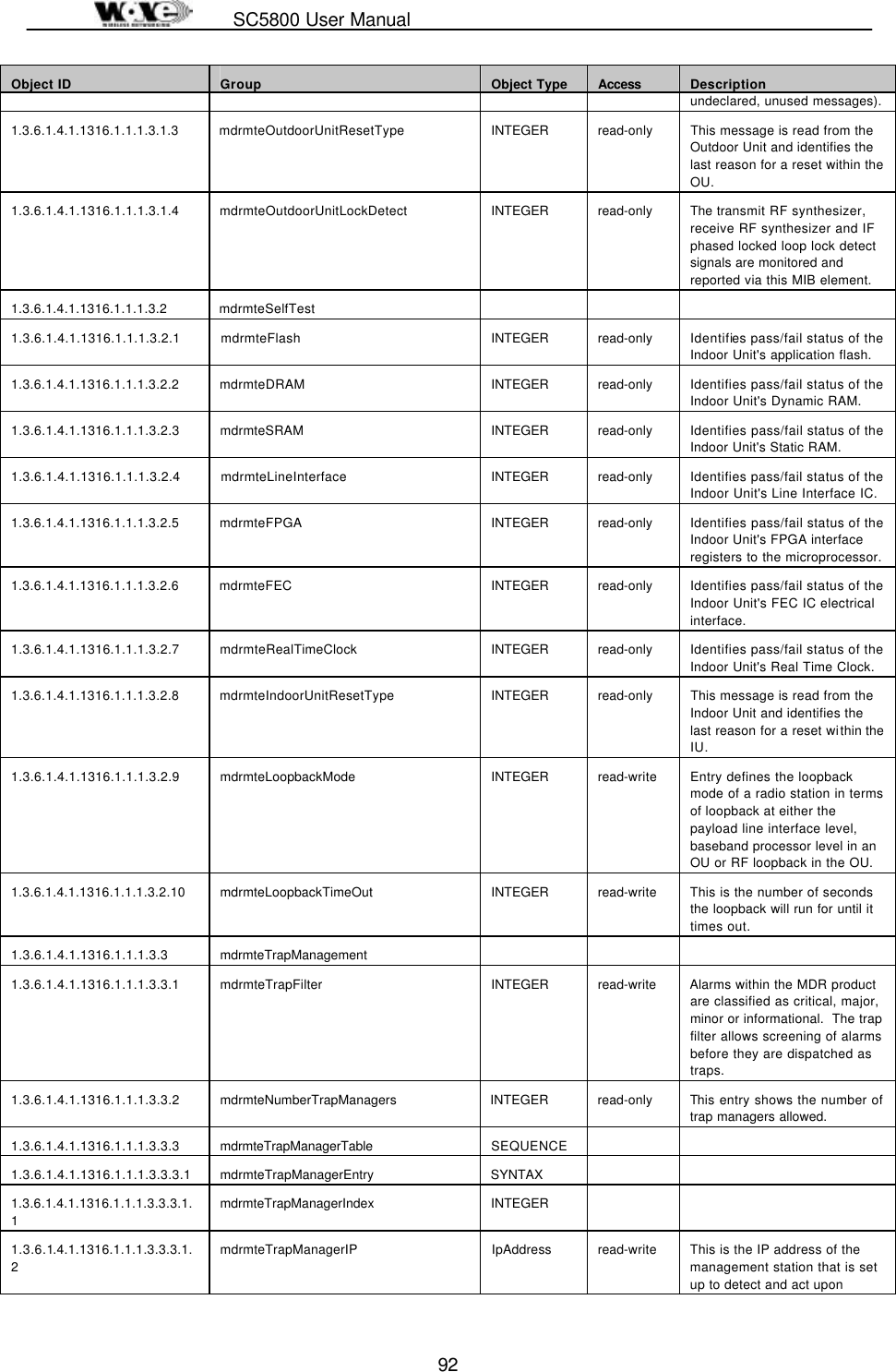
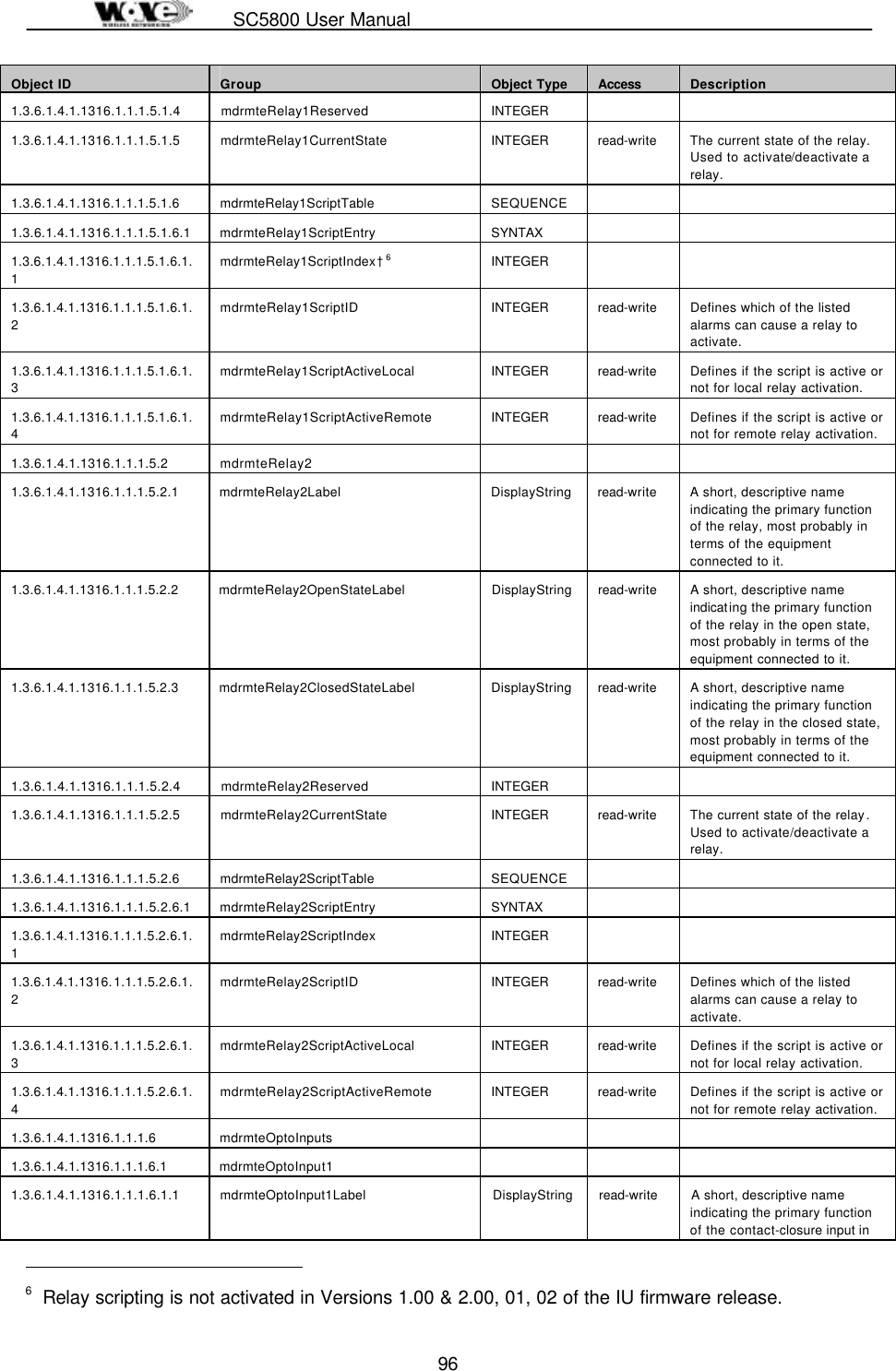
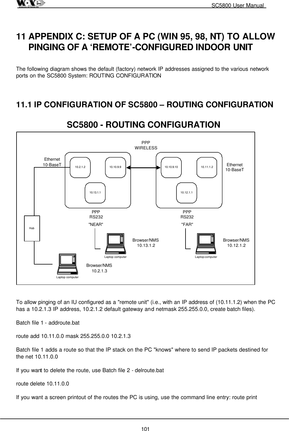
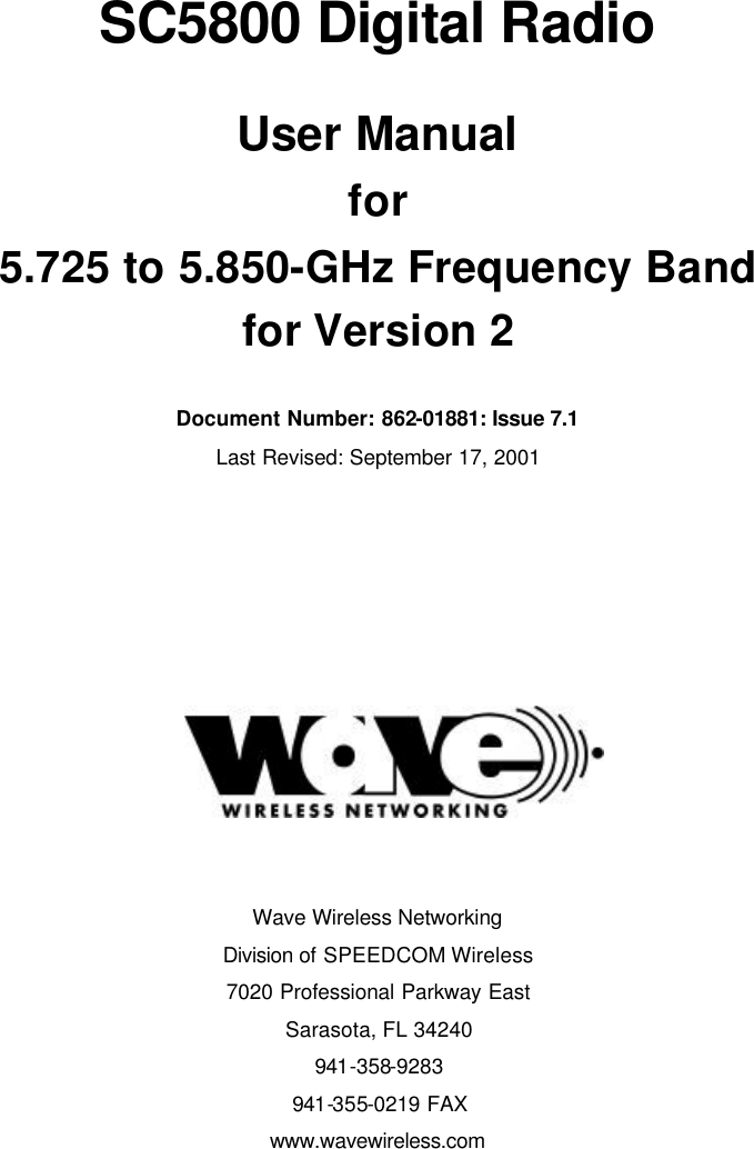
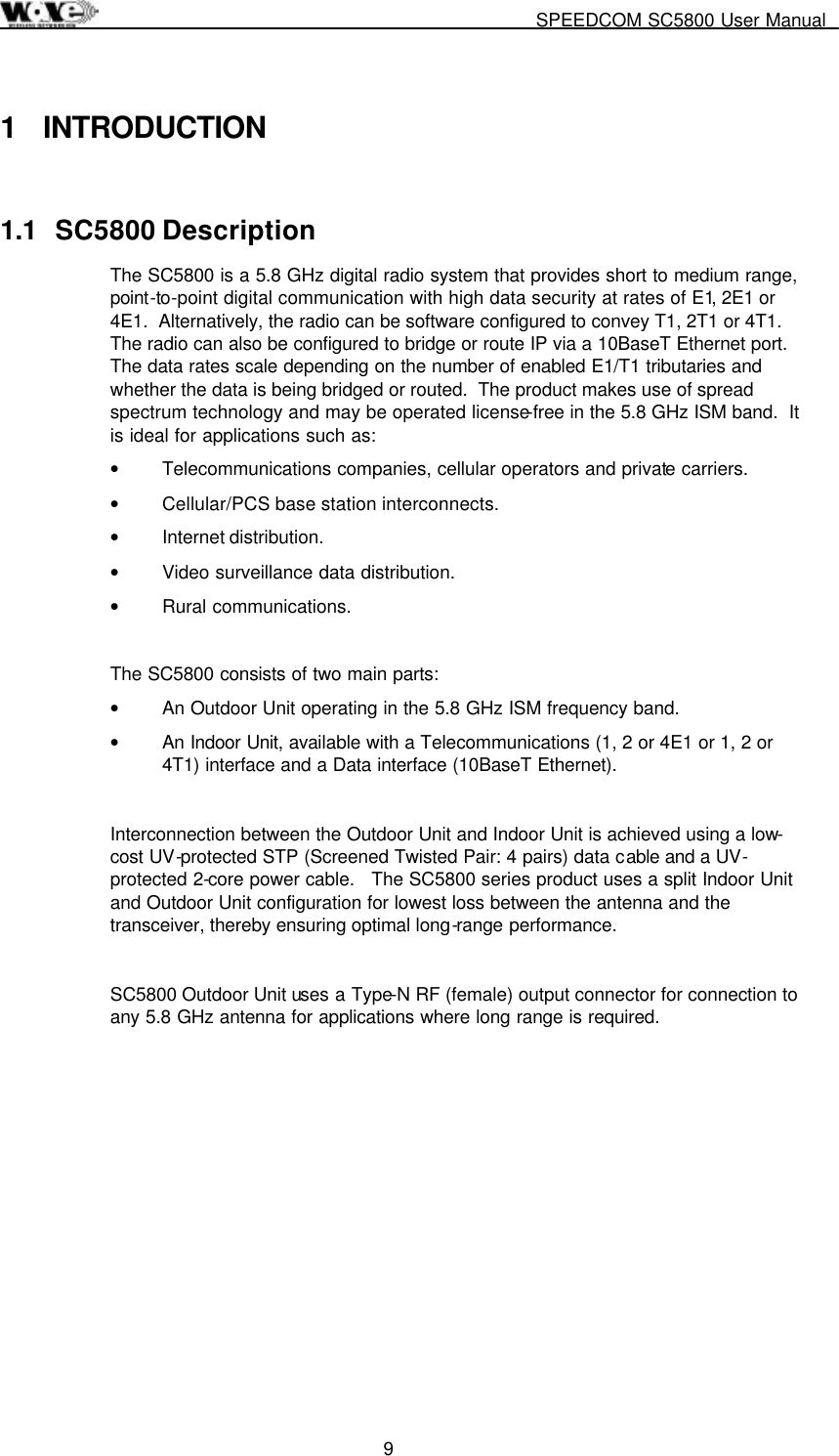
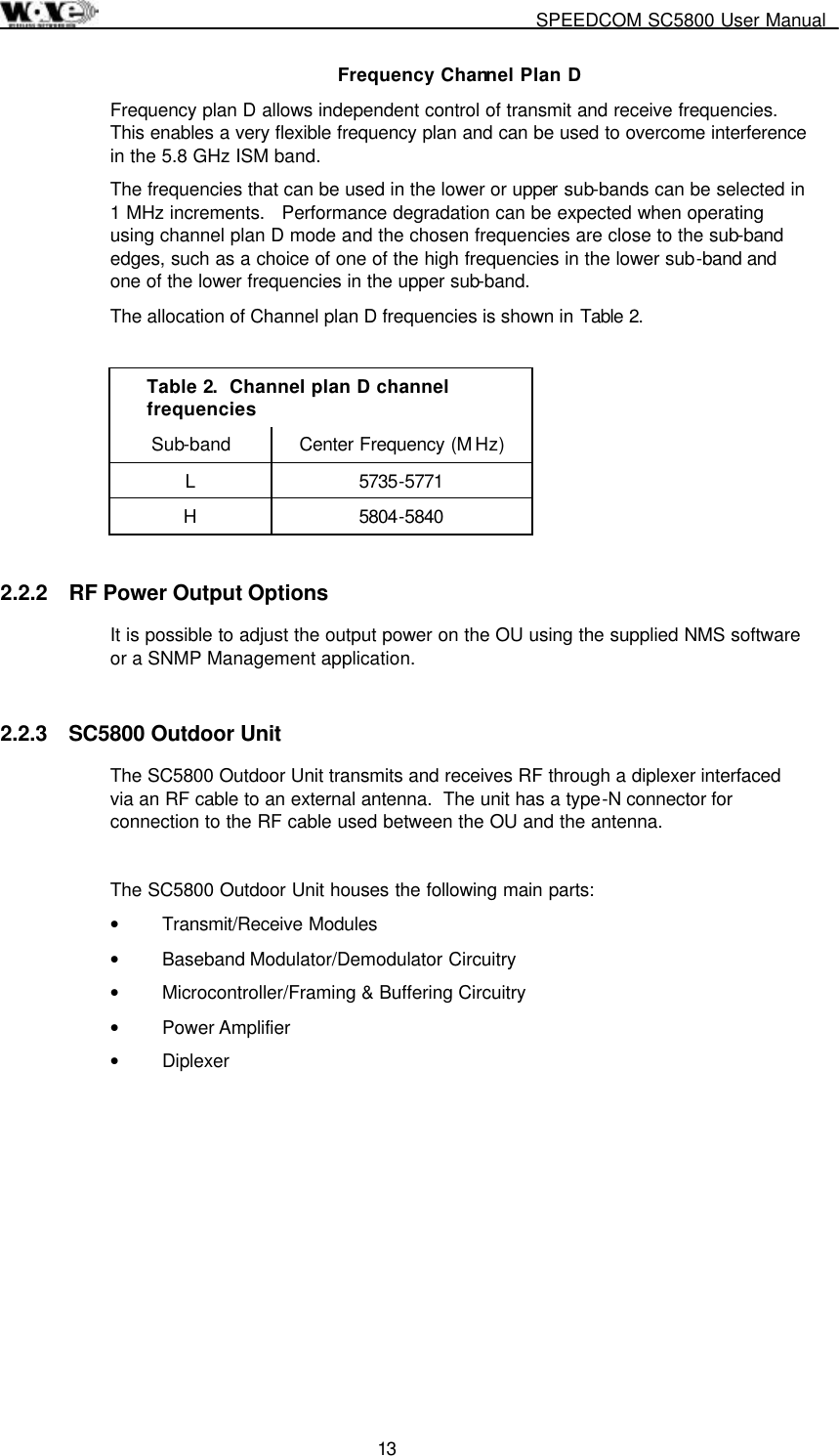
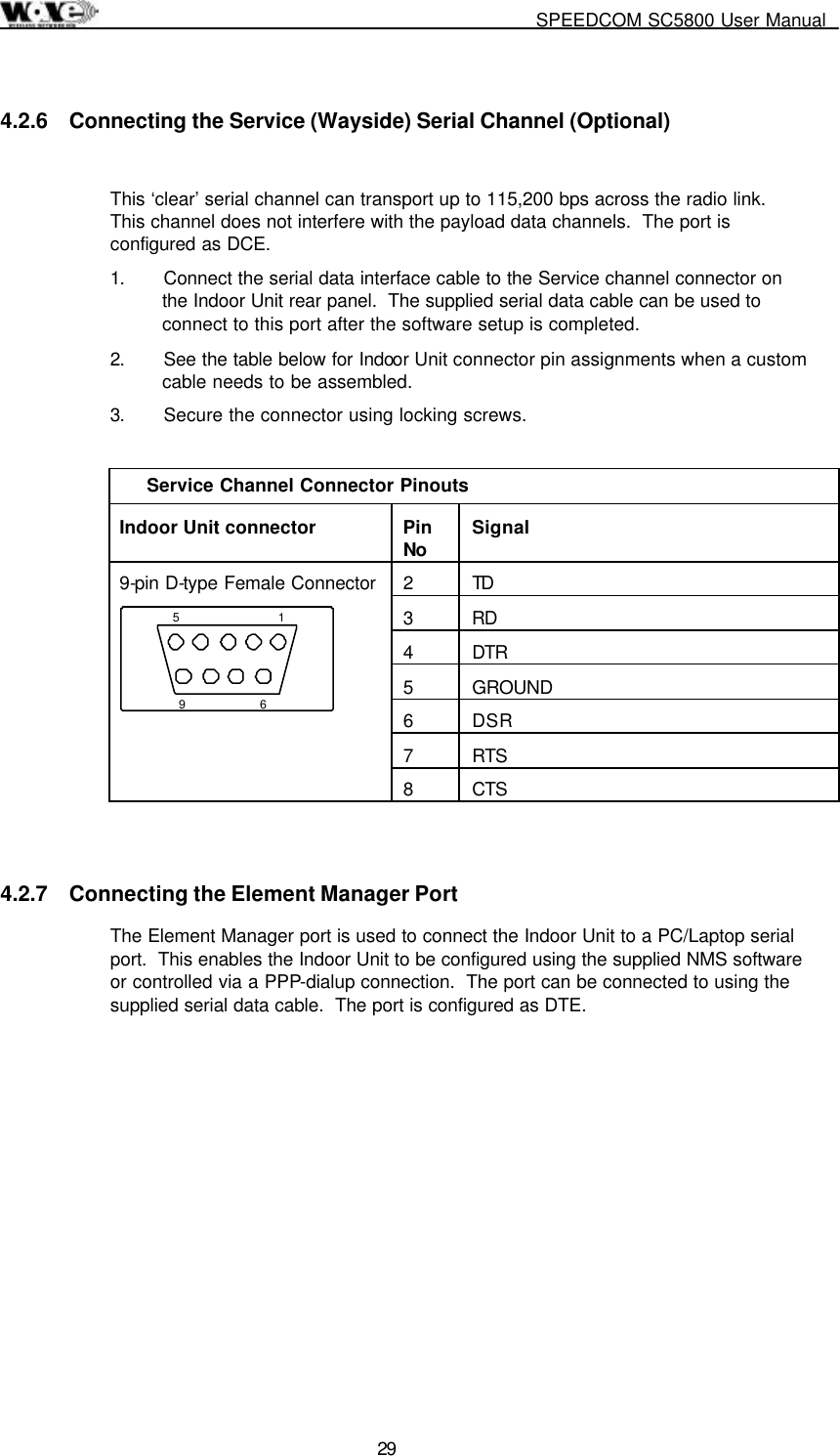
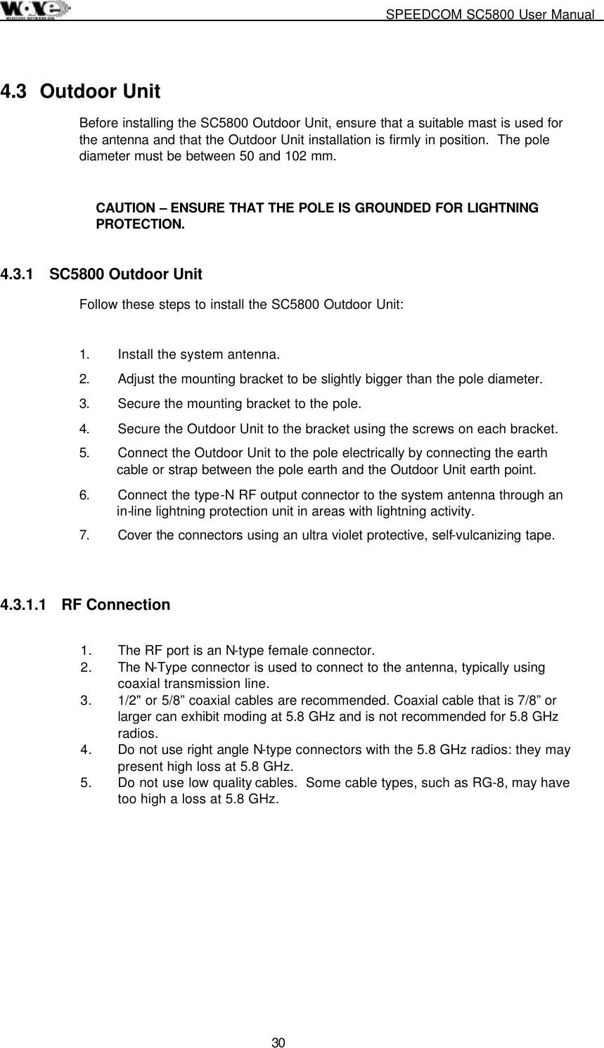
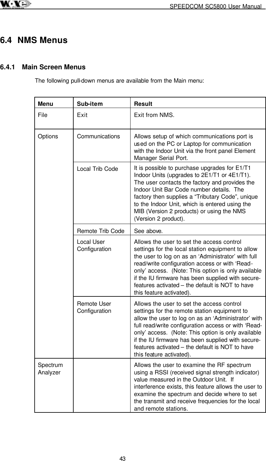
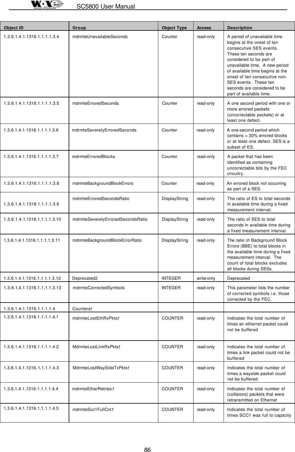
![SC5800 User Manual 89 Object ID Group Object Type Access Description defines the receive frequency of the Outdoor Unit. 1.3.6.1.4.1.1316.1.1.1.2.2.13 mdrmteNonAutoBandPlan INTEGER read-write Same as mdrMTEBandPlan setting in this MIB group except “auto recovery” is not enabled - this allows control of the Outdoor Unit frequencies without the “auto recovery” feature attempting to intervene and re-establish setup of an operational RF Link. 1.3.6.1.4.1.1316.1.1.1.2.2.14 mdrmteNonAutoTxFreqPlanD INTEGER read-write Same as mdrTxFrequencyPlanD setting in this MIB group except “auto recovery” is not enabled - this allows control of the Outdoor Unit Plan D frequencies without the “auto recovery” feature attempting to intervene and re-establish setup of an operational RF Link. 1.3.6.1.4.1.1316.1.1.1.2.2.15 mdrmteNonAutoRxFreqPlanD INTEGER read-write Same as mdrTxFrequencyPlanD setting in this MIB group except “auto recovery” is not enabled - this allows control of the Outdoor Unit Plan D frequencies without the “auto recovery” feature attempting to intervene and re-establish setup of an operational RF Link. 1.3.6.1.4.1.1316.1.1.1.2.2.16 mdrmteNonAutoTxPower INTEGER read-write Same as mdrTxPower setting in this MIB group except “auto recovery” is not enabled - this allows control of the Outdoor Unit power level setting without the “auto recovery” feature attempting to intervene and re-establish setup of an operational RF Link. 1.3.6.1.4.1.1316.1.1.1.2.3 mdrmteServiceChannel 1.3.6.1.4.1.1316.1.1.1.2.3.1 mdrmteScDataRate†3 INTEGER read-write Bit rate used across the wayside service channel link. 1.3.6.1.4.1.1316.1.1.1.2.3.2 mdrmteScDataBits†4 INTEGER read-write The data width - can be 7 or 8 bits. 1.3.6.1.4.1.1316.1.1.1.2.3.3 MdrmteScParity INTEGER read-write Serial channel - set to none, odd or even. 1.3.6.1.4.1.1316.1.1.1.2.3.4 MdrmteScStopBits INTEGER read-write The number of stop bits can be set to 1 or 2. 1.3.6.1.4.1.1316.1.1.1.2.3.5 mdrmteScFlowControl INTEGER read-write Either hardware or no flow control is used. 1.3.6.1.4.1.1316.1.1.1.2.3.6 mdrmteScStatusDump INTEGER read-write Allows the wayside service (serial) channel to be used as a diagnostics port [deprecated]. 1.3.6.1.4.1.1316.1.1.1.2.4 MdrmteGeneral 1.3.6.1.4.1.1316.1.1.1.2.4.1 MdrmteStationName DisplayString read-write The station name is stored in the Indoor Unit in non-volatile 3 Fixed at 115.2kbps in Version 1.00 and 2.00, 2.01, 2.02 IU firmware releases. 4 Serial setting – 8 bits, no parity, 1 stop bit](https://usermanual.wiki/Wave-Wireless-Networking/SLSC5800/User-Guide-172242-Page-91.png)