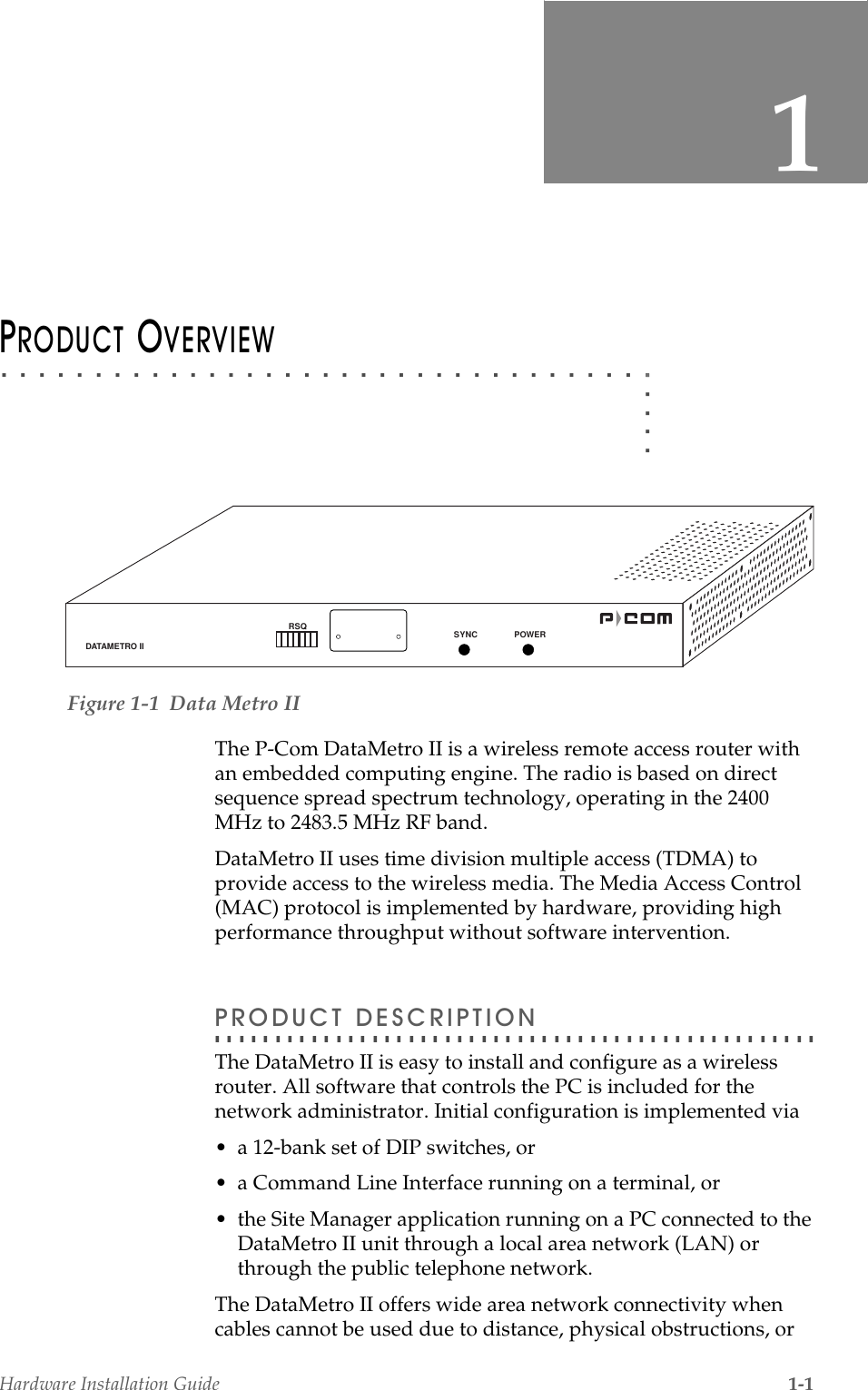
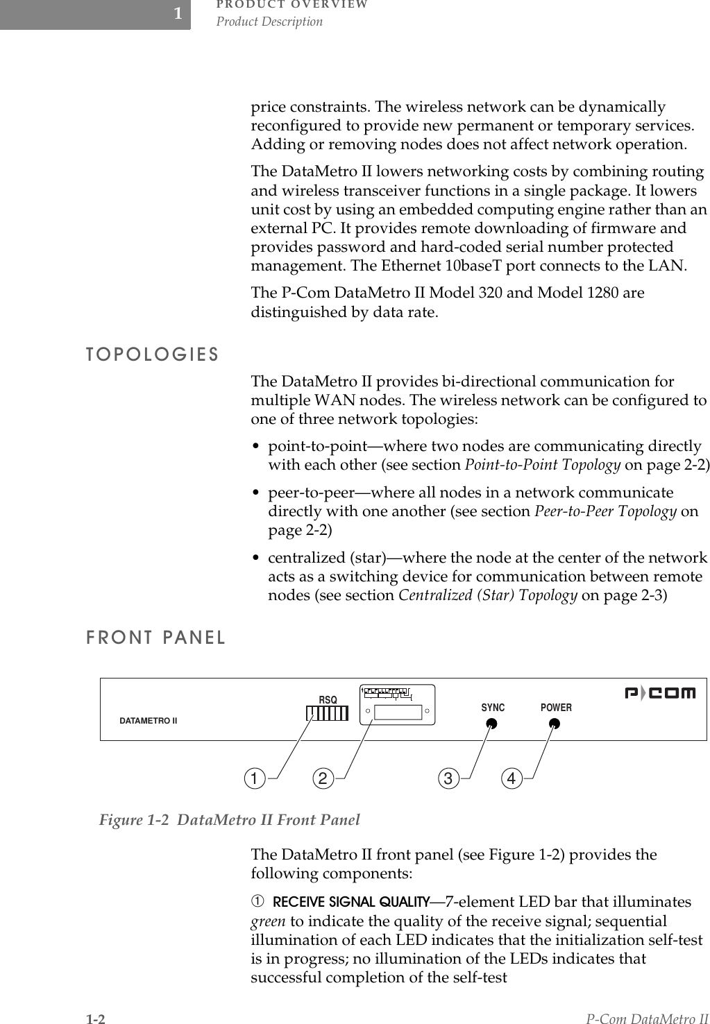
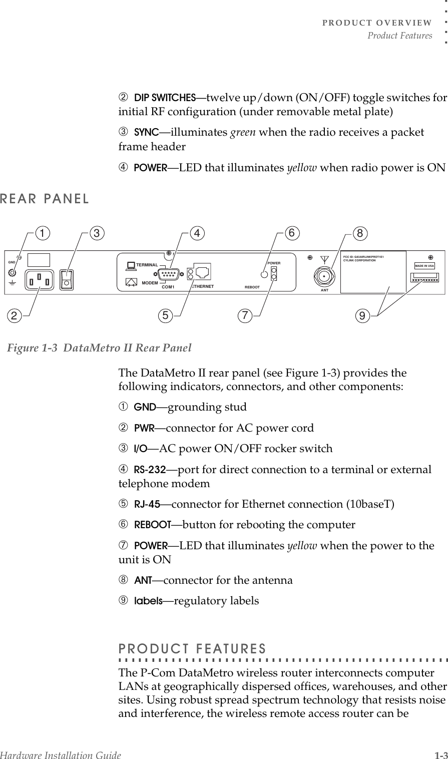
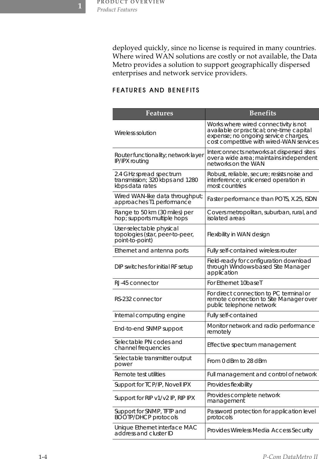
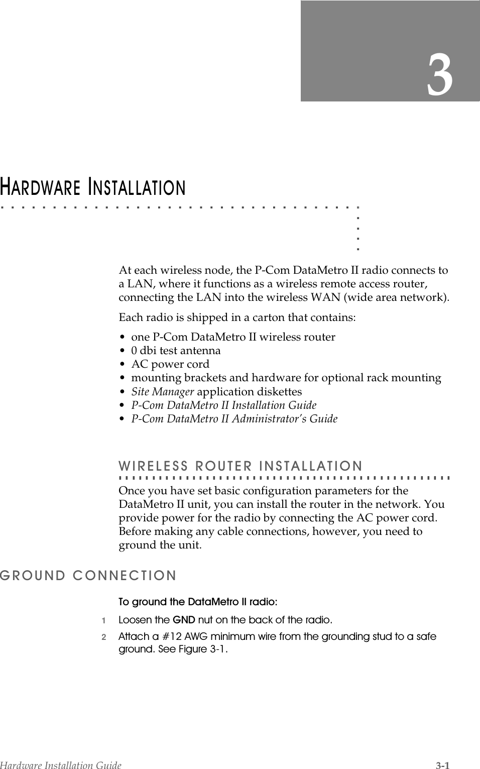
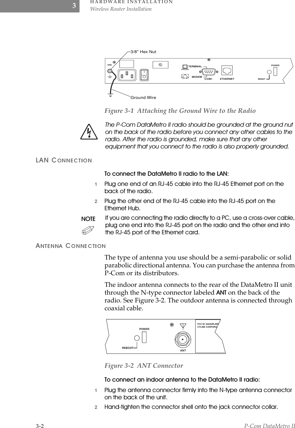
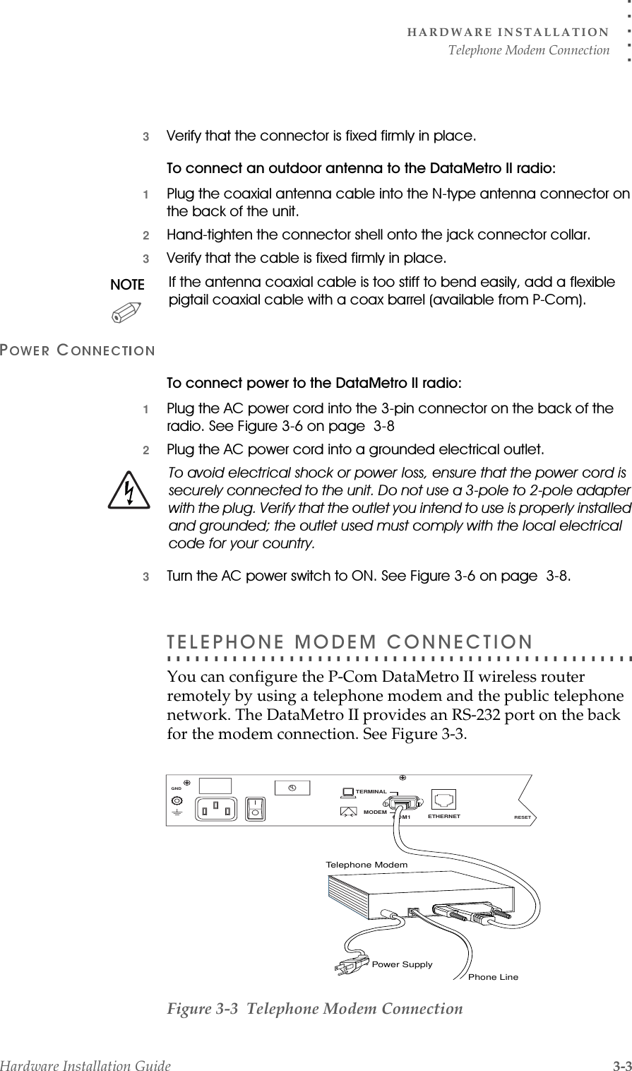
Wave Wireless DM2 Wireless Data Link User Manual
Wave Wireless Corporation Wireless Data Link
UserManual.wiki
>
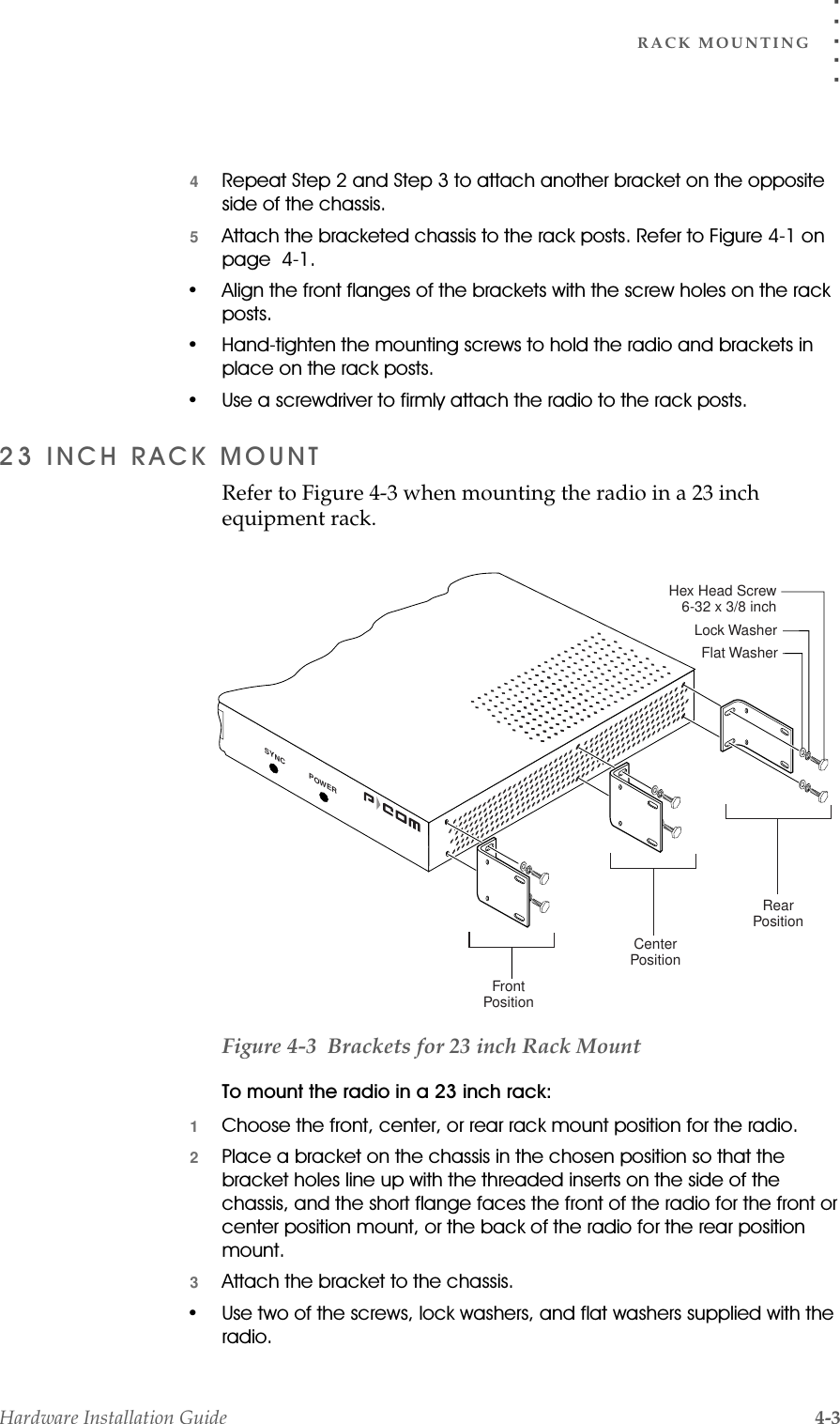
Wave Wireless
>
DM2 User Manual
>
User Manual
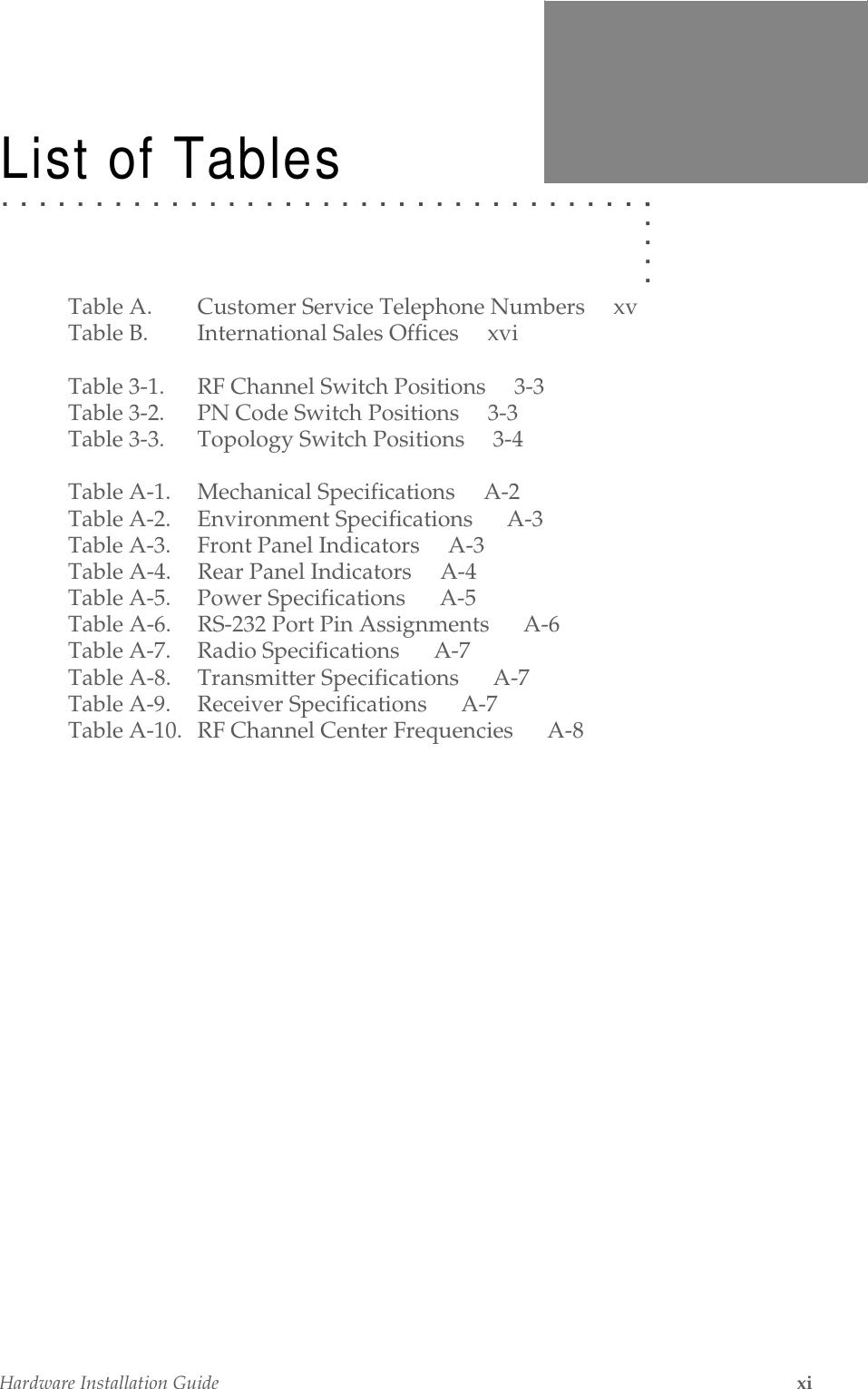
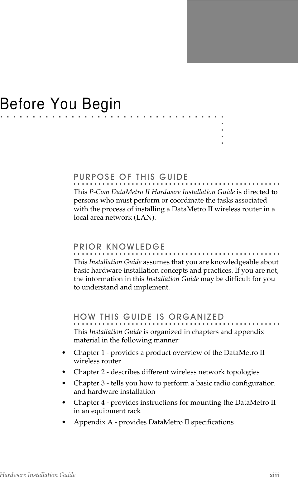
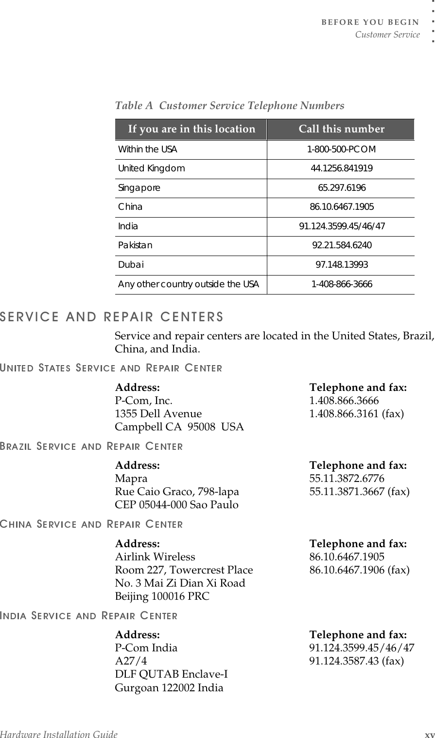
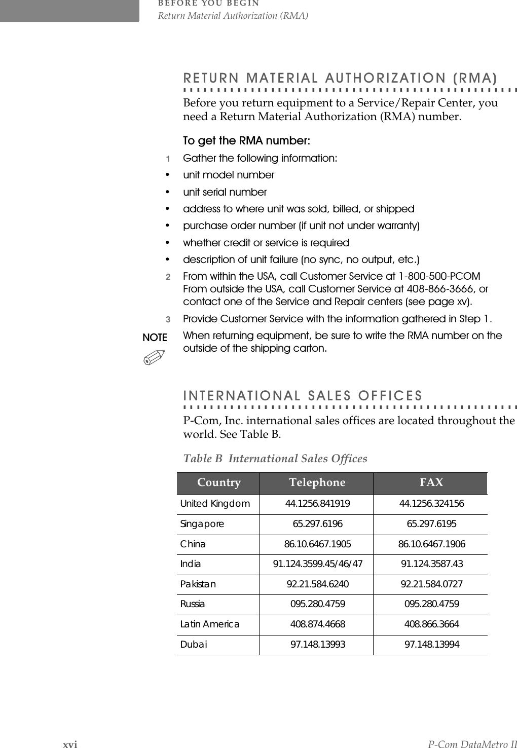
Contents
1.
Product Data Sheet
2.
User Manual
3.
Reply 6594 p2p and p2mp instructions to installer
User Manual
Navigation menu
Upload a User Manual
Namespaces
Wiki Guide
HTML
PDF
Info
Views
User Manual
Discussion / Help
Navigation