Wave Wireless DM2 Wireless Data Link User Manual
Wave Wireless Corporation Wireless Data Link
Contents
User Manual

P-Com DataMetro II
Wireless Router
Hardware Installation Guide
Rev A

© COPYRIGHT 1999 P-Com Inc. World Rights reserved.
P-Com Inc. provides this Installation Guide without warranty of any kind, either express or
implied, including, but not limited to, the implied warranties of merchantability and fitness for
a particular purpose.
P-Com Inc. may make improvements and changes to the product described in this manual
at any time and without any notice. P-Com Inc. assumes no responsibility for its use, nor any
infringements of patents or other rights of third parties that would result.
This publication may contain technical inaccuracies or typographical errors. Periodic
changes are made to the information contained herein. These changes, and mechanical
corrections, will be incorporated in subsequent revision levels of the publication.
No part of this publication may be stored in a retrieval system, transmitted, or reproduced in
any way, including but not limited to photocopy, photograph, magnetic or other records,
without the prior written permission of P-Com Inc.
DataMetro and AirLink
are trademarks of P-Com Inc.
All other brand and product names are the trademarks of their respective holders.
P/N 81170-010 Rev A
TPN 81170-00A
February 1999
STATEMENT OF WARRANTY
This product, except as stated otherwise in an applicable price list, is warranted against defects in
workmanship and material for a period of three (3) years from date of delivery as evidenced by the
manufacturer’s packing slip or other transportation receipt.
The manufacturer’s sole responsibility under this warranty shall be to either repair or replace, at its
option, any component which fails during the applicable warranty period because of a defect in
workmanship and material, provided PURCHASER has promptly reported same to the manufacturer
in writing. All replaced Products or parts shall become property of the manufacturer.
P-Com shall honor the warranty at its repair facility in Campbell, California. It is PURCHASER’s
responsibility to return, at its expense, the allegedly defective Product to the manufacturer.
PURCHASER must obtain a Return Materials Authorization (RMA) number and shipping instructions
from the manufacturer prior to returning any Product under warranty. Transportation charges for the
return of the Product to PURCHASER shall be paid by the manufacturer within the United States. For
all other locations, the warranty excludes all costs of shipping, customs clearance and other related
charges. If the manufacturer determines that the Product is not defective within the terms of the
warranty, PURCHASER shall pay to the manufacturer all costs of handling, transportation and repairs
at the then prevailing repair rates.
All the above warranties are contingent upon proper use of the Product. These warranties will not
apply (i) if adjustment, repair or parts replacement is required because of accident, unusual physical,
electrical or electromagnetic stress, negligence of PURCHASER, misuse, failure of electric power,
environmental controls, transportation, not maintained in accordance with manufacturer’s
specifications, or abuses other than ordinary use (ii) if the Product has been modified by
PURCHASER or has been repaired or altered outside the factory, unless the manufacturer
specifically authorizes such repairs or alterations; (iii) where manufacturer serial numbers, warranty
data or quality assurance decals have been removed or altered.
P-Com also reserves the right to make product improvements without incurring any obligation or
liability to make the same changes in Products previously manufactured or purchased. In no event
shall the manufacturer be liable for any breach of warranty in an amount exceeding the net selling
price of any defective Product. No person, including any dealer, agent or representative of P-Com is
authorized to assume for P-Com any other liability on its behalf except as set forth herein.
Nonpayment of any invoice rendered within the stated payment terms automatically cancels any
warranty or guarantee stated or implied. If any payment is due to the manufacturer for services
performed hereunder, it shall be subject to the same payment terms as the original purchase.
P-COM HEREBY DISCLAIMS ALL IMPLIED WARRANTIES ON PRODUCTS INCLUDING
WITHOUT LIMITATION, ALL IMPLIED WARRANTIES OF MERCHANTABILITY OR FITNESS FOR
A PARTICULAR PURPOSE. The warranties expressly stated herein are the sole obligation or liability
on the part of P-COM arising out of or in connection with the sale or performance of the products.
Products Manufactured by Others - For products not manufactured by P-COM, the original
manufacturer’s warranty shall be assigned to PURCHASER to the extent permitted and is in lieu of
any other warranty, express or implied. For warranty information on a specific product, a written
request should be made to the manufacturer.
IN NO EVENT WILL P-COM BE LIABLE TO PURCHASER FOR (i) REPROCUREMENT COSTS; (ii)
SPECIAL, INDIRECT OR CONSEQUENTIAL DAMAGES; (iii) ANY DAMAGES WHATSOEVER
RESULTING FROM LOSS OF USE, DATA OR PROFITS ARISING OUT OF OR IN CONNECTION
WITH THIS AGREEMENT, OR THE USE OR PERFORMANCE OF P-COM PRODUCTS,
REGARDLESS OF WHETHER THE CAUSE OF ACTION IS IN CONTRACT, TORT, INCLUDING
NEGLIGENCE, OR ANY OTHER FORM.
No action, whether in contract or tort, including negligence, arising out of or in connection with this
Agreement, may be brought by either party more than eighteen (18) months after the cause of action
has accrued, except that an action for nonpayment may be brought within eighteen (18) months of
the date of last payment.

PRODUCT COMPATIBILITY
While every effort has been made to verify operation of this product with many different communications
products and networks, P-Com Corporation makes no claim of compatibility between its products and other
vendors’ equipment. It is assumed that users have thoroughly evaluated this product’s performance in the
communications environment in which it will be used.
SAFETY
The following general safety precautions must be observed during all phases of operation and service of this
product. Failure to comply with these precautions or with specific warnings elsewhere in this Manual willfully
violates standards of design, manufacture, and intended use of the product. P-Com Corporation assumes no
liability for the customer’s failure to comply with these requirements.
This product must be grounded. In the event of a short circuit, grounding reduces the risk of electrical shock
by providing an escape wire for the current.
We recommend that you use preferred power—a dedicated power circuit with an assigned circuit breaker.
The product’s AC power cord ends in a three-pole grounding plug. Do not use a three-pole to two-pole adapter
with the plug. Verify that the outlet you intend to use is properly installed and grounded; the outlet used must
comply with the National Electric Code (NEC) NFPA70 (1990) in U.S.A. or other local and national or
international applicable code.
Do not install or operate this product in the presence of flammable gases or fumes. Operation of any electrical
instrument in such an environment constitutes a definite safety hazard.
No user maintained or adjustable components are present within this product. Do NOT attempt to open this
unit. Do not attempt to service this unit except under the direction of Customer Service. Only P-Com-authorized
service personnel should service this equipment. The potential for electrical shock exists within the enclosures
at all times unless they are unplugged.
Do not install substitute parts or perform any unauthorized modification to the product. Return the product to
the factory for service and repair to ensure that safety features are maintained. Prior to returning any product(s)
for repair, contact P-Com at the telephone numbers or address located in this Manual, and obtain a Return
Material Authorization (RMA) number.
Changes or modifications not expressly approved by P-Com Corporation can void the user’s authority to
operate this equipment.
SYSTEM GROUNDING
Direct grounding of the antenna, mast, and tower serves as protection from lightning strikes and static buildup.
A direct electrical connection should be made to a suitable grounding rod at the base of the tower or mast using
at least #10 AWG ground wire, or its equivalent, and non-corrosive hardware. For details and safety standards,
consult the appropriate local Electrical Codes or a similar document. Use lightning arresters in appropriate
places.
TOWER CONSTRUCTION
Compliance with local zoning and tower construction regulations is recommended when DataMetro II systems
require a tower. These regulations generally mandate that permits be obtained before any tower construction
begins. Check with local zoning and aviation authorities for more information.

FCC NOTICE TO USERS
This device complies with Part 15 of the FCC rules. Operation is subject to the following two conditions:
(1) This device may not cause harmful interference, and
(2) This device must accept any interference that may cause undesired operation.
Changes or modifications not expressly approved by P-Com Inc. can void the user’s authority to operate the
equipment.
FCC regulations require that this device be professionally installed by a person knowledgeable in electronics
and trained in the correct installation of this device.
All interface cables must be shielded.
CANADIAN DEPARTMENT OF COMMUNICATIONS COMPLIANCE
This Class B digital apparatus meets all the requirements of the Canadian Interference-Causing Equipment
Regulations. This digital apparatus does not exceed the Class B limits for radio noise from digital apparatus
as set out in the Radio Interference Regulations of the Canadian Department of Communications.
Cet appareil numérique de la classe B respecte toutes les exigences du Règlement sur le matériel brouilleur
du Canada.

Hardware Installation Guide v
. . . . .
. . . . . . . . . . . . . . . . . . . . . . . . . . . . . . . . . . .
Contents
Before You Begin
.
.
.
.
.
.
.
.
.
.
.
.
.
.
.
.
.
.
.
.
.
.
.
.
.
.
.
.
.
.
.
.
.
.
.
.
.
.
.
.
.
.
.
.
.
.
.
.
.
.
Purpose of This Guide xiii
.
.
.
.
.
.
.
.
.
.
.
.
.
.
.
.
.
.
.
.
.
.
.
.
.
.
.
.
.
.
.
.
.
.
.
.
.
.
.
.
.
.
.
.
.
.
.
.
.
.
Prior Knowledge xiii
.
.
.
.
.
.
.
.
.
.
.
.
.
.
.
.
.
.
.
.
.
.
.
.
.
.
.
.
.
.
.
.
.
.
.
.
.
.
.
.
.
.
.
.
.
.
.
.
.
.
How This Guide is Organized xiii
.
.
.
.
.
.
.
.
.
.
.
.
.
.
.
.
.
.
.
.
.
.
.
.
.
.
.
.
.
.
.
.
.
.
.
.
.
.
.
.
.
.
.
.
.
.
.
.
.
.
How to Use This Guide xiv
.
.
.
.
.
.
.
.
.
.
.
.
.
.
.
.
.
.
.
.
.
.
.
.
.
.
.
.
.
.
.
.
.
.
.
.
.
.
.
.
.
.
.
.
.
.
.
.
.
.
Typographic Conventions xiv
.
.
.
.
.
.
.
.
.
.
.
.
.
.
.
.
.
.
.
.
.
.
.
.
.
.
.
.
.
.
.
.
.
.
.
.
.
.
.
.
.
.
.
.
.
.
.
.
.
.
Customer Service xiv
E-mail Service xiv
Telephone and Fax Service xiv
Service and Repair Centers xv
United States Service and Repair Center xv
Brazil Service and Repair Center xv
China Service and Repair Center xv
India Service and Repair Center xv
.
.
.
.
.
.
.
.
.
.
.
.
.
.
.
.
.
.
.
.
.
.
.
.
.
.
.
.
.
.
.
.
.
.
.
.
.
.
.
.
.
.
.
.
.
.
.
.
.
.
Return Material Authorization (RMA) xvi
.
.
.
.
.
.
.
.
.
.
.
.
.
.
.
.
.
.
.
.
.
.
.
.
.
.
.
.
.
.
.
.
.
.
.
.
.
.
.
.
.
.
.
.
.
.
.
.
.
.
International Sales Offices xvi
Chapter 1. Product Overview
.
.
.
.
.
.
.
.
.
.
.
.
.
.
.
.
.
.
.
.
.
.
.
.
.
.
.
.
.
.
.
.
.
.
.
.
.
.
.
.
.
.
.
.
.
.
.
.
.
.
Product Description 1-1
Topologies 1-2
Front Panel 1-2
Rear Panel 1-3
.
.
.
.
.
.
.
.
.
.
.
.
.
.
.
.
.
.
.
.
.
.
.
.
.
.
.
.
.
.
.
.
.
.
.
.
.
.
.
.
.
.
.
.
.
.
.
.
.
.
Product Features 1-4

CONTENTS
vi P-Com DataMetro II
Chapter 2. Wireless Network Design
.
.
.
.
.
.
.
.
.
.
.
.
.
.
.
.
.
.
.
.
.
.
.
.
.
.
.
.
.
.
.
.
.
.
.
.
.
.
.
.
.
.
.
.
.
.
.
.
.
.
Packet-Based Networks 2-1
.
.
.
.
.
.
.
.
.
.
.
.
.
.
.
.
.
.
.
.
.
.
.
.
.
.
.
.
.
.
.
.
.
.
.
.
.
.
.
.
.
.
.
.
.
.
.
.
.
.
Point-to-Point Topology 2-2
.
.
.
.
.
.
.
.
.
.
.
.
.
.
.
.
.
.
.
.
.
.
.
.
.
.
.
.
.
.
.
.
.
.
.
.
.
.
.
.
.
.
.
.
.
.
.
.
.
.
Peer-to-Peer Topology 2-2
.
.
.
.
.
.
.
.
.
.
.
.
.
.
.
.
.
.
.
.
.
.
.
.
.
.
.
.
.
.
.
.
.
.
.
.
.
.
.
.
.
.
.
.
.
.
.
.
.
.
Centralized (Star) Topology 2-3
Chapter 3. Hardware Installation
.
.
.
.
.
.
.
.
.
.
.
.
.
.
.
.
.
.
.
.
.
.
.
.
.
.
.
.
.
.
.
.
.
.
.
.
.
.
.
.
.
.
.
.
.
.
.
.
.
.
Basic Configuration Setup 3-1
DIP Switches 3-2
Command Line Interface 3-4
Autobaud Process 3-6
Site Manager Application 3-7
.
.
.
.
.
.
.
.
.
.
.
.
.
.
.
.
.
.
.
.
.
.
.
.
.
.
.
.
.
.
.
.
.
.
.
.
.
.
.
.
.
.
.
.
.
.
.
.
.
.
Wireless Router Installation 3-7
Ground Connection 3-8
LAN Connection 3-8
Antenna Connection 3-8
Power Connection 3-9
.
.
.
.
.
.
.
.
.
.
.
.
.
.
.
.
.
.
.
.
.
.
.
.
.
.
.
.
.
.
.
.
.
.
.
.
.
.
.
.
.
.
.
.
.
.
.
.
.
.
Telephone Modem Connection 3-9
Chapter 4. Rack Mounting
19 inch Rack Mount 4-2
23 inch Rack Mount 4-3
Appendix A.Specifications
.
.
.
.
.
.
.
.
.
.
.
.
.
.
.
.
.
.
.
.
.
.
.
.
.
.
.
.
.
.
.
.
.
.
.
.
.
.
.
.
.
.
.
.
.
.
.
.
.
.
Year 2000 Compliance A-1
.
.
.
.
.
.
.
.
.
.
.
.
.
.
.
.
.
.
.
.
.
.
.
.
.
.
.
.
.
.
.
.
.
.
.
.
.
.
.
.
.
.
.
.
.
.
.
.
.
.
General Specifications A-2
LED Indicators A-3

. . . . .
CONTENTS
Hardware Installation Guide vii
DIP Switches A-4
External Connectors A-5
AC Power Connector A-5
Antenna Connector A-5
Backup/Terminal Connector A-5
Ethernet Connector A-6
.
.
.
.
.
.
.
.
.
.
.
.
.
.
.
.
.
.
.
.
.
.
.
.
.
.
.
.
.
.
.
.
.
.
.
.
.
.
.
.
.
.
.
.
.
.
.
.
.
.
Radio Specifications A-7
.
.
.
.
.
.
.
.
.
.
.
.
.
.
.
.
.
.
.
.
.
.
.
.
.
.
.
.
.
.
.
.
.
.
.
.
.
.
.
.
.
.
.
.
.
.
.
.
.
.
Center Frequencies A-8
Index

CONTENTS
viii P-Com DataMetro II

Hardware Installation Guide ix
. . . . .
. . . . . . . . . . . . . . . . . . . . . . . . . . . . . . . . . . .
List of Figures
Figure 1-1. Data Metro II 1-1
Figure 1-2. DataMetro II Front Panel 1-2
Figure 1-3. DataMetro II Rear Panel 1-3
Figure 2-1. Point-to-Point Topology 2-2
Figure 2-2. Peer-to-Peer Topology 2-3
Figure 2-3. Star Topology 2-4
Figure 3-1. DIP Switches 3-2
Figure 3-2. Connecting the Terminal or PC 3-5
Figure 3-3. Connecting the Power Cord 3-5
Figure 3-4. Attaching the Ground Wire to the Radio 3-8
Figure 3-5. ANT Connector 3-8
Figure 3-6. Telephone Modem Connection 3-10
Figure 4-1. Rack Mounted Radios 4-1
Figure 4-2. Brackets for 19 inch Rack Mount 4-2
Figure 4-3. Brackets for 23 inch Rack Mount 4-3
Figure A-1. Radio Dimensions A-2
Figure A-2. Front Panel Indicators A-3
Figure A-3. Rear Panel Indicators A-4
Figure A-4. DIP Switch Positions A-4
Figure A-5. AC Power Connector A-5
Figure A-6. Antenna Connector A-5
Figure A-7. RS-232 Backup/Terminal Connector A-5
Figure A-8. Ethernet Jack A-6

LIST OF FIGURES
xP-Com DataMetro II

Hardware Installation Guide xi
. . . . .
. . . . . . . . . . . . . . . . . . . . . . . . . . . . . . . . . . .
List of Tables
Table A. Customer Service Telephone Numbers xv
Table B. International Sales Offices xvi
Table 3-1. RF Channel Switch Positions 3-3
Table 3-2. PN Code Switch Positions 3-3
Table 3-3. Topology Switch Positions 3-4
Table A-1. Mechanical Specifications A-2
Table A-2. Environment Specifications A-3
Table A-3. Front Panel Indicators A-3
Table A-4. Rear Panel Indicators A-4
Table A-5. Power Specifications A-5
Table A-6. RS-232 Port Pin Assignments A-6
Table A-7. Radio Specifications A-7
Table A-8. Transmitter Specifications A-7
Table A-9. Receiver Specifications A-7
Table A-10. RF Channel Center Frequencies A-8

LIST OF TABLES
xii P-Com DataMetro II

Hardware Installation Guide xiii
. . . . .
. . . . . . . . . . . . . . . . . . . . . . . . . . . . . . . . . . .
Before You Begin
. . . . . . . . . . . . . . . . . . . . . . . . . . . . . . . . . . . . . . . . . . . . . . . . . .
385326(2)7+,6*8,'(
This P-Com DataMetro II Hardware Installation Guide is directed to
persons who must perform or coordinate the tasks associated
with the process of installing a DataMetro II wireless router in a
local area network (LAN).
. . . . . . . . . . . . . . . . . . . . . . . . . . . . . . . . . . . . . . . . . . . . . . . . . .
35,25.12:/('*(
This Installation Guide assumes that you are knowledgeable about
basic hardware installation concepts and practices. If you are not,
the information in this Installation Guide may be difficult for you
to understand and implement.
. . . . . . . . . . . . . . . . . . . . . . . . . . . . . . . . . . . . . . . . . . . . . . . . . .
+2:7+,6*8,'(,625*$1,=('
This Installation Guide is organized in chapters and appendix
material in the following manner:
• Chapter 1 - provides a product overview of the DataMetro II
wireless router
• Chapter 2 - describes different wireless network topologies
• Chapter 3 - tells you how to perform a basic radio configuration
and hardware installation
• Chapter 4 - provides instructions for mounting the DataMetro II
in an equipment rack
• Appendix A - provides DataMetro II specifications

BEFORE YOU BEGIN
How to Use This Guide
xiv P-Com DataMetro II
. . . . . . . . . . . . . . . . . . . . . . . . . . . . . . . . . . . . . . . . . . . . . . . . . .
+2:7286(7+,6*8,'(
Before beginning the installation process, review all the chapters
so that you have a sense of what each chapter provides. Verify
that you have selected the proper installation procedure to meet
site-specific needs.
Read through an entire procedure before you begin performing
the step-by-step instructions. By doing this, you will be prepared
with the appropriate information, equipment, or tools.
. . . . . . . . . . . . . . . . . . . . . . . . . . . . . . . . . . . . . . . . . . . . . . . . . .
7<32*5$3+,&&219(17,216
Notes, Cautions, and Warnings are shown as:
$QRWHJLYHV\RXLQIRUPDWLRQRIVSHFLDOLQWHUHVW
$FDXWLRQJLYHV\RXLQIRUPDWLRQWKDW\RXQHHGVRWKDW\RXZLOOQRW
GDPDJHWKHHTXLSPHQWRUORVHGDWD
$ZDUQLQJJLYHV\RXLQIRUPDWLRQWKDW\RXQHHGVRWKDW\RXGRQRW
FDXVHKDUPWR\RXUVHOIRUDQ\RWKHUSHUVRQDQGVRWKDW\RXGRQRW
GDPDJHRULQWHUIHUHZLWKWKHQHWZRUNDSSOLFDWLRQ
. . . . . . . . . . . . . . . . . . . . . . . . . . . . . . . . . . . . . . . . . . . . . . . . . .
&86720(56(59,&(
P-Com distributors are authorized local service providers and are
responsible for immediate customer support. If problems are not
resolved, you can contact P-Com Customer Service for assistance.
(0$,/6(59,&(
P-Com Customer Service provides the following e-mail address
for customer assistance:
FXVWRPHUBVHUYLFH#SFRPFRP
7(/(3+21($1')$;6(59,&(
P-Com Customer Service maintains a 24-hour answering service
for emergency telephone support. Customer Service responses to
emergency calls consist of over-the-phone troubleshooting and
assistance in obtaining distributor support.
See Table A for Customer Service telephone numbers.
127(
✐
. . . . .
BEFORE YOU BEGIN
Customer Service
Hardware Installation Guide xv
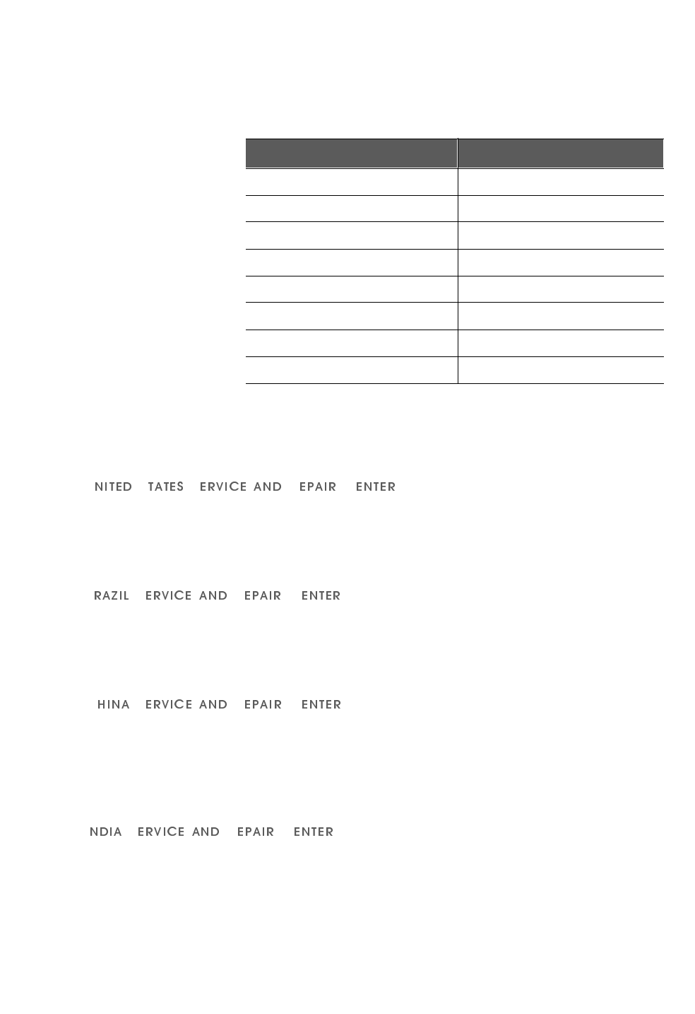
6(59,&($1'5(3$,5&(17(56
Service and repair centers are located in the United States, Brazil,
China, and India.
86 6 5 &
Address: Telephone and fax:
P-Com, Inc. 1.408.866.3666
1355 Dell Avenue 1.408.866.3161 (fax)
Campbell CA 95008 USA
%6 5 &
Address: Telephone and fax:
Mapra 55.11.3872.6776
Rue Caio Graco, 798-lapa 55.11.3871.3667 (fax)
CEP 05044-000 Sao Paulo
&6 5 &
Address: Telephone and fax:
Airlink Wireless 86.10.6467.1905
Room 227, Towercrest Place 86.10.6467.1906 (fax)
No. 3 Mai Zi Dian Xi Road
Beijing 100016 PRC
,6 5 &
Address: Telephone and fax:
P-Com India 91.124.3599.45/46/47
A27/4 91.124.3587.43 (fax)
DLF QUTAB Enclave-I
Gurgoan 122002 India
Table A Customer Service Telephone Numbers
If you are in this location Call this number
Within the USA 1-800-500-PCOM
United Kingdom 44.1256.841919
Singapore 65.297.6196
China 86.10.6467.1905
India 91.124.3599.45/46/47
Pakistan 92.21.584.6240
Dubai 97.148.13993
Any other country outside the USA 1-408-866-3666

BEFORE YOU BEGIN
Return Material Authorization (RMA)
xvi P-Com DataMetro II
. . . . . . . . . . . . . . . . . . . . . . . . . . . . . . . . . . . . . . . . . . . . . . . . . .
5(78510$7(5,$/$87+25,=$7,2150$
Before you return equipment to a Service/Repair Center, you
need a Return Material Authorization (RMA) number.
7RJHWWKH50$QXPEHU
1*DWKHUWKHIROORZLQJLQIRUPDWLRQ
XQLWPRGHOQXPEHU
XQLWVHULDOQXPEHU
DGGUHVVWRZKHUHXQLWZDVVROGELOOHGRUVKLSSHG
SXUFKDVHRUGHUQXPEHULIXQLWQRWXQGHUZDUUDQW\
ZKHWKHUFUHGLWRUVHUYLFHLVUHTXLUHG
GHVFULSWLRQRIXQLWIDLOXUHQRV\QFQRRXWSXWHWF
2)URPZLWKLQWKH86$FDOO&XVWRPHU6HUYLFHDW3&20
)URPRXWVLGHWKH86$FDOO&XVWRPHU6HUYLFHDWRU
FRQWDFWRQHRIWKH6HUYLFHDQG5HSDLUFHQWHUVVHHSDJH[Y
33URYLGH&XVWRPHU6HUYLFHZLWKWKHLQIRUPDWLRQJDWKHUHGLQ6WHS
:KHQUHWXUQLQJHTXLSPHQWEHVXUHWRZULWHWKH50$QXPEHURQWKH
RXWVLGHRIWKHVKLSSLQJFDUWRQ
. . . . . . . . . . . . . . . . . . . . . . . . . . . . . . . . . . . . . . . . . . . . . . . . . .
,17(51$7,21$/6$/(62)),&(6
P-Com, Inc. international sales offices are located throughout the
world. See Table B.
Table B International Sales Offices
Country Telephone FAX
United Kingdom 44.1256.841919 44.1256.324156
Singapore 65.297.6196 65.297.6195
China 86.10.6467.1905 86.10.6467.1906
India 91.124.3599.45/46/47 91.124.3587.43
Pakistan 92.21.584.6240 92.21.584.0727
Russia 095.280.4759 095.280.4759
Latin America 408.874.4668 408.866.3664
Dubai 97.148.13993 97.148.13994
127(
✐
Hardware Installation Guide 1-1
1
. . . . .
. . . . . . . . . . . . . . . . . . . . . . . . . . . . . . . . . . .
3
52'8&7
2
9(59,(:
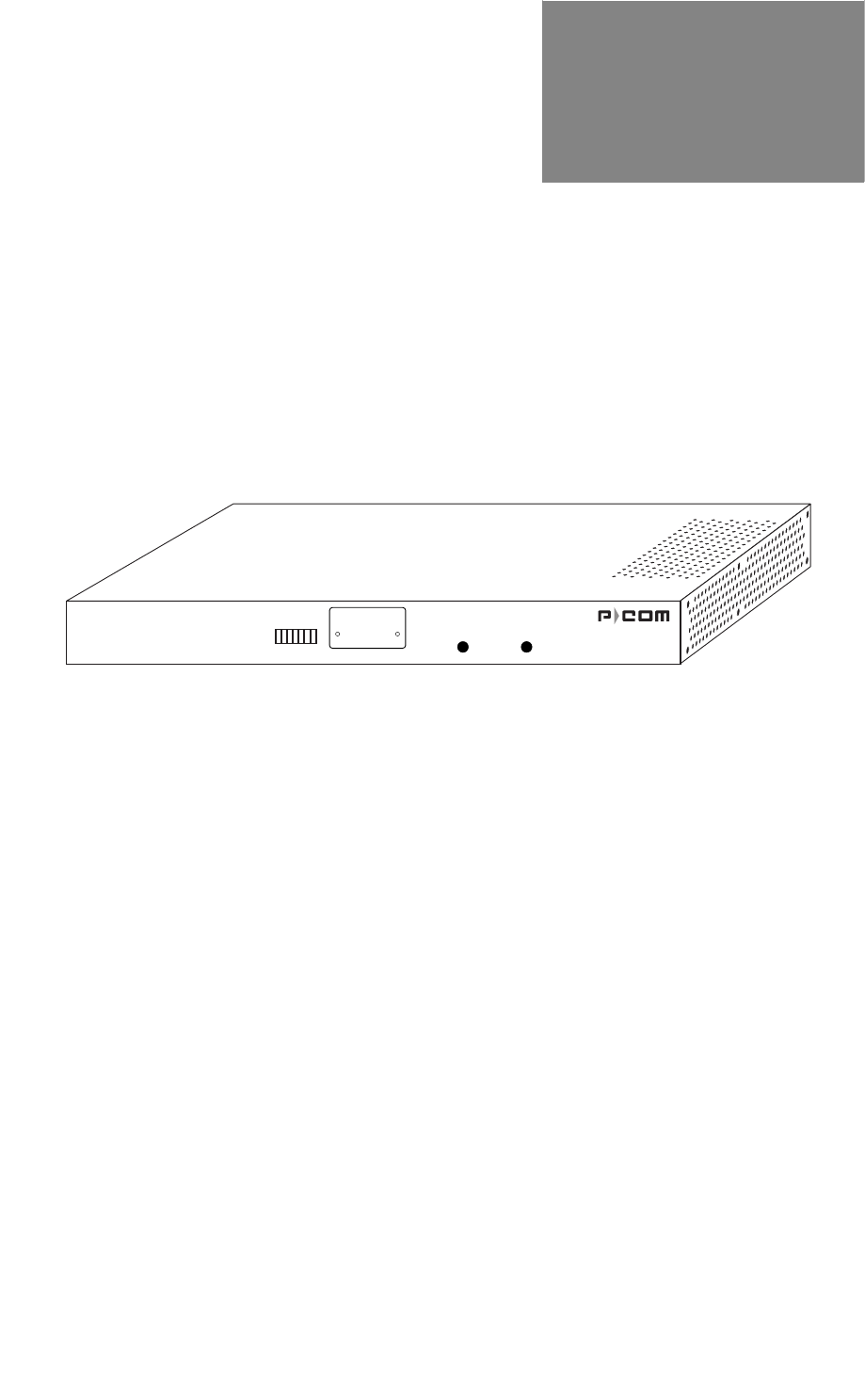
Figure 1-1 Data Metro II
The P-Com DataMetro II is a wireless remote access router with
an embedded computing engine. The radio is based on direct
sequence spread spectrum technology, operating in the 2400
MHz to 2483.5 MHz RF band.
DataMetro II uses time division multiple access (TDMA) to
provide access to the wireless media. The Media Access Control
(MAC) protocol is implemented by hardware, providing high
performance throughput without software intervention.
. . . . . . . . . . . . . . . . . . . . . . . . . . . . . . . . . . . . . . . . . . . . . . . . . .
352'8&7'(6&5,37,21
The DataMetro II is easy to install and configure as a wireless
router. All software that controls the PC is included for the
network administrator. Initial configuration is implemented via
• a 12-bank set of DIP switches, or
• a Command Line Interface running on a terminal, or
• the Site Manager application running on a PC connected to the
DataMetro II unit through a local area network (LAN) or
through the public telephone network.
The DataMetro II offers wide area network connectivity when
cables cannot be used due to distance, physical obstructions, or
DATAMETRO II
RSQ SYNC POWER
PRODUCT OVERVIEW
Product Description
1-2 P-Com DataMetro II
1
price constraints. The wireless network can be dynamically
reconfigured to provide new permanent or temporary services.
Adding or removing nodes does not affect network operation.
The DataMetro II lowers networking costs by combining routing
and wireless transceiver functions in a single package. It lowers
unit cost by using an embedded computing engine rather than an
external PC. It provides remote downloading of firmware and
provides password and hard-coded serial number protected
management. The Ethernet 10baseT port connects to the LAN.
The P-Com DataMetro II Model 320 and Model 1280 are
distinguished by data rate.
7232/2*,(6
The DataMetro II provides bi-directional communication for
multiple WAN nodes. The wireless network can be configured to
one of three network topologies:
• point-to-point—where two nodes are communicating directly
with each other (see section Point-to-Point Topology on page 2-2)
• peer-to-peer—where all nodes in a network communicate
directly with one another (see section Peer-to-Peer Topology on
page 2-2)
• centralized (star)—where the node at the center of the network
acts as a switching device for communication between remote
nodes (see section Centralized (Star) Topology on page 2-3)
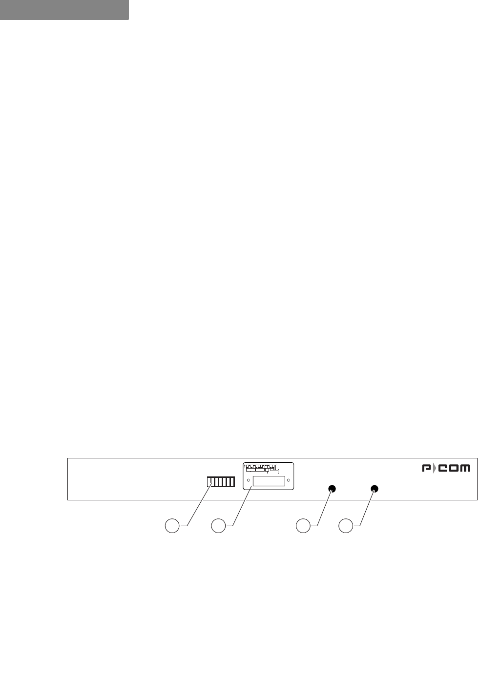
)52173$1(/
Figure 1-2 DataMetro II Front Panel
The DataMetro II front panel (see Figure 1-2) provides the
following components:
➀5(&(,9(6,*1$/48$/,7<—7-element LED bar that illuminates
green to indicate the quality of the receive signal; sequential
illumination of each LED indicates that the initialization self-test
is in progress; no illumination of the LEDs indicates that
successful completion of the self-test
DATAMETRO II
RSQ SYNC POWER
1 2 3 4
. . . . .
PRODUCT OVERVIEW
Product Features
Hardware Installation Guide 1-3
➁',36:,7&+(6³twelve up/down (ON/OFF) toggle switches for
initial RF configuration (under removable metal plate)
➂6<1&—illuminates green when the radio receives a packet
frame header
➃32:(5—LED that illuminates yellow when radio power is ON
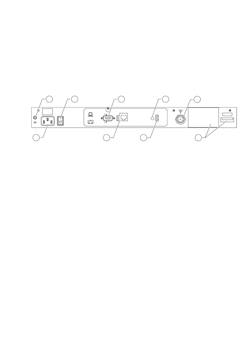
5($53$1(/
Figure 1-3 DataMetro II Rear Panel
The DataMetro II rear panel (see Figure 1-3) provides the
following indicators, connectors, and other components:
➀*1'—grounding stud
➁3:5—connector for AC power cord
➂,2—AC power ON/OFF rocker switch
➃56—port for direct connection to a terminal or external
telephone modem
➄5-—connector for Ethernet connection (10baseT)
➅5(%227—button for rebooting the computer
➆32:(5—LED that illuminates yellow when the power to the
unit is ON
➇$17—connector for the antenna
➈ODEHOV—regulatory labels
. . . . . . . . . . . . . . . . . . . . . . . . . . . . . . . . . . . . . . . . . . . . . . . . . .
352'8&7)($785(6
The P-Com DataMetro wireless router interconnects computer
LANs at geographically dispersed offices, warehouses, and other
sites. Using robust spread spectrum technology that resists noise
and interference, the wireless remote access router can be
GND
ANT
POWER
REBOOT
COM1
MODEM
TERMINAL
ETHERNET
2
31 68
xxxxxxxxxx
FCC ID: G83AIRLINKPROT1E1
CYLINK CORPORATION
MADE IN USA
9
75
4

PRODUCT OVERVIEW
Product Features
1-4 P-Com DataMetro II
1
deployed quickly, since no license is required in many countries.
Where wired WAN solutions are costly or not available, the Data
Metro provides a solution to support geographically dispersed
enterprises and network service providers.
)($785(6$1'%(1(),76
Features Benefits
Wireless solution Works where wired connectivity is not
available or practical; one-time capital
expense; no ongoing service charges,
cost competitive with wired-WAN services
Router functionality; network layer
IP/IPX routing Interconnects networks at dispersed sites
over a wide area; maintains independent
networks on the WAN
2.4 GHz spread spectrum
transmission; 320 kbps and 1280
kbps data rates
Robust, reliable, secure; resists noise and
interference; unlicensed operation in
most countries
Wired WAN-like data throughput;
approaches T1 performance Faster performance than POTS, X.25, ISDN
Range to 50 km (30 miles) per
hop; supports multiple hops Covers metropolitan, suburban, rural, and
isolated areas
User-selectable physical
topologies (star, peer-to-peer,
point-to-point) Flexibility in WAN design
Ethernet and antenna ports Fully self-contained wireless router
DIP switches for initial RF setup Field-ready for configuration download
through Windows-based Site Manager
application
RJ-45 connector For Ethernet 10baseT
RS-232 connector For direct connection to PC terminal or
remote connection to Site Manager over
public telephone network
Internal computing engine Fully self-contained
End-to-end SNMP support Monitor network and radio performance
remotely
Selectable PN codes and
channel frequencies Effective spectrum management
Selectable transmitter output
power From 0 dBm to 28 dBm
Remote test utilities Full management and control of network
Support for TCP/IP, Novell IPX Provides flexibility
Support for RIP v1/v2 IP, RIP IPX Provides complete network
management
Support for SNMP, TFTP and
BOOTP/DHCP protocols Password protection for application level
protocols
Unique Ethernet interface MAC
address and cluster ID Provides Wireless Media Access Security

Hardware Installation Guide 2-1
2
. . . . .
. . . . . . . . . . . . . . . . . . . . . . . . . . . . . . . . . . .
:
,5(/(66
1
(7:25.
'
(6,*1
The term network topology refers to the logical layout of a network.
It defines how the network elements will communicate with each
other, how the information will be transmitted, and how the
information will be routed through the network.
. . . . . . . . . . . . . . . . . . . . . . . . . . . . . . . . . . . . . . . . . . . . . . . . . .
3$&.(7%$6('1(7:25.6
Packet-based networks are most suitable for data that come in
bursts, such as networks that involve large-scale data
transmissions for multiple users at the same time. There is a
guaranteed minimum throughput for a packet-based network,
but the actual throughput realized by a packet-based network
node will depend on
• the number of users in the network, and
• how much traffic is being generated by each node at any given
time.
The advantage of a packet-based network is that multiple
transmissions can travel along the network at the same time,
using whatever path is appropriate to the routing from the source
to the destination.
The most significant characteristic of packet-based networks is
the wireless interface access protocols they use, such as
CSMA/CA (Carrier Sense Multiple Access/Collision Avoidance),
which can result in more efficient use of the aggregate bandwidth
by dynamically allocating throughput to nodes based on
demand.
P-Com DataMetro II supports Point-to-Point, Peer-to-Peer, and
Centralized (Star) packet-based network topologies. Each
topology has its own optimized wireless protocol.
WIRELESS NETWORK DESIGN
Point-to-Point Topology
2-2 P-Com DataMetro II
2
. . . . . . . . . . . . . . . . . . . . . . . . . . . . . . . . . . . . . . . . . . . . . . . . . .
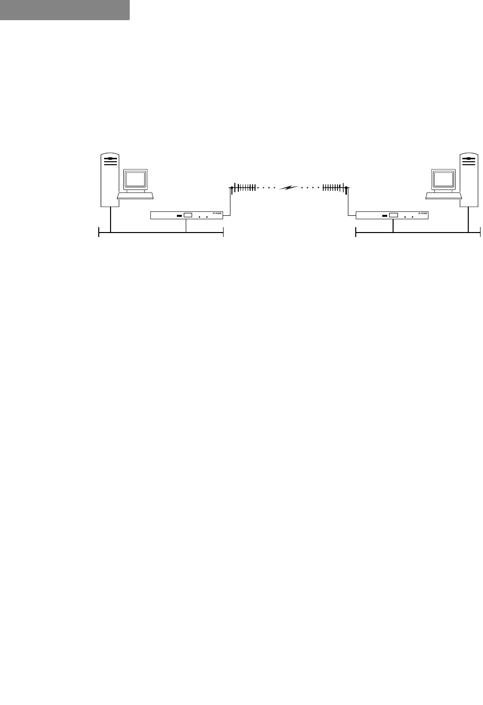
32,177232,177232/2*<
In a packet-based point-to-point topology, two nodes are linked
directly. The most common application for this topology would
be the interconnection of two LANs. In Figure 2-1, the LANs are
connected via a pair of DataMetro II routers.
Figure 2-1 Point-to-Point Topology
The range and interference immunity that can be achieved with
packet-based point-to-point topology is maximized by the use of
highly directional antennas on both sides of the link.
DataMetro II applies native modification of the CSMA/CA
protocol for the point-to-point topology. Each node sends its
frame immediately after receiving a frame, in which case the
delay value is equal to zero. The node that sent the frame will
wait for a reply. If there is no reply, it will send the next frame
using the standard CSMA/CA protocol.
. . . . . . . . . . . . . . . . . . . . . . . . . . . . . . . . . . . . . . . . . . . . . . . . . .
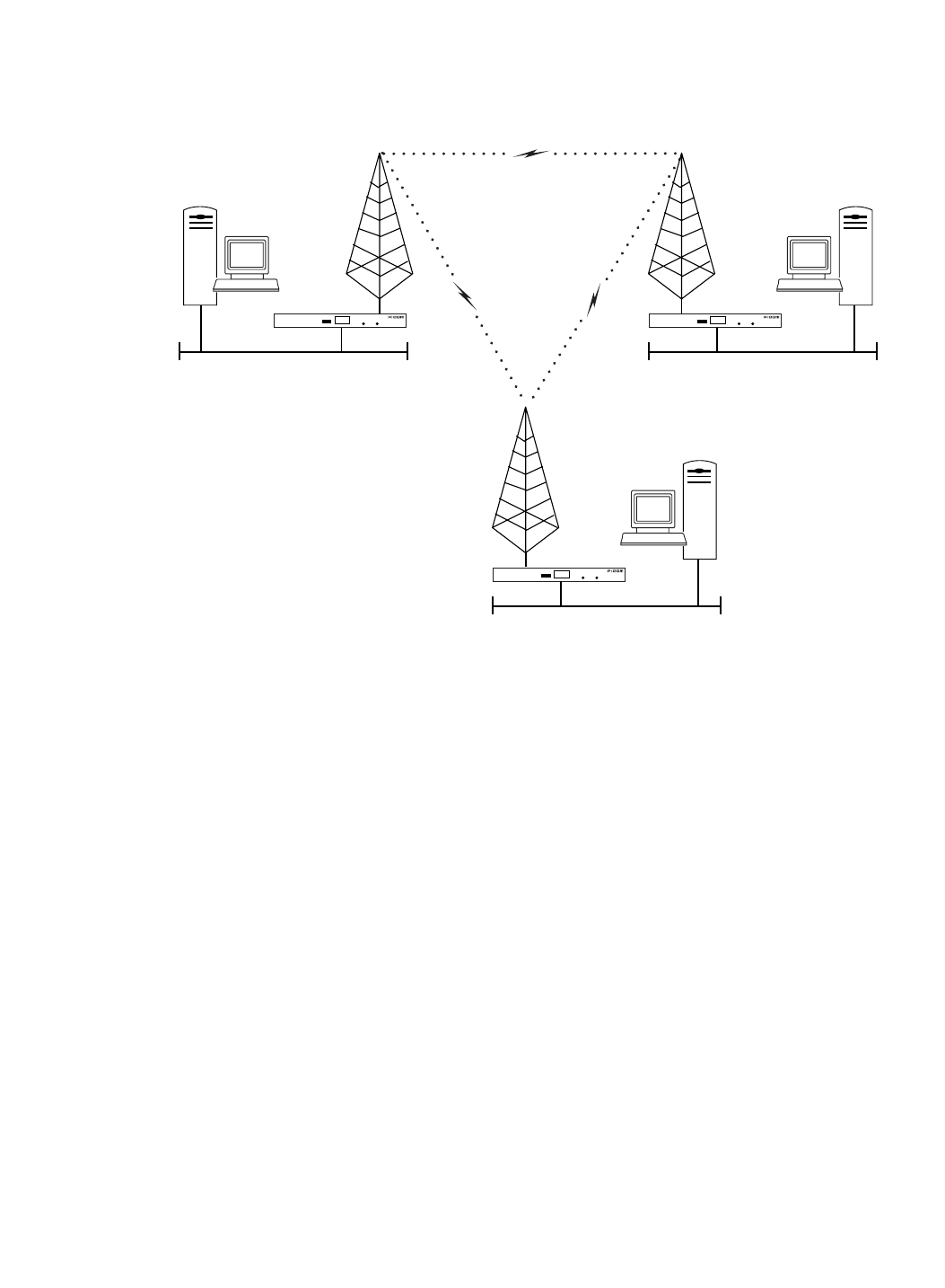
3((5723((57232/2*<
In peer-to-peer topology (unique to packet-based networks),
there are three or more nodes, any one of which can communicate
directly with any other node. Since each node has direct access to
every other node, the time delay for transferring data between
nodes is the least for this type of topology, unless WAN traffic is
very high. However, this also implies that each node must have a
clear communication path to every other node, that is, there must
be clear line of sight.
An example of a three node peer-to-peer topology is shown in
Figure 2-2 on page 2-3.
DATAMETRO II DATAMETRO II
Ethernet Ethernet
. . . . .
WIRELESS NETWORK DESIGN
Centralized (Star) Topology
Hardware Installation Guide 2-3
Figure 2-2 Peer-to-Peer Topology
In peer-to-peer topology, since all nodes need to talk to each
other, the range is dependent on the type of antennas used and
the local terrain. Longer ranges can be achieved by using
directional antennas with power splitters to connect to all sites.
. . . . . . . . . . . . . . . . . . . . . . . . . . . . . . . . . . . . . . . . . . . . . . . . . .
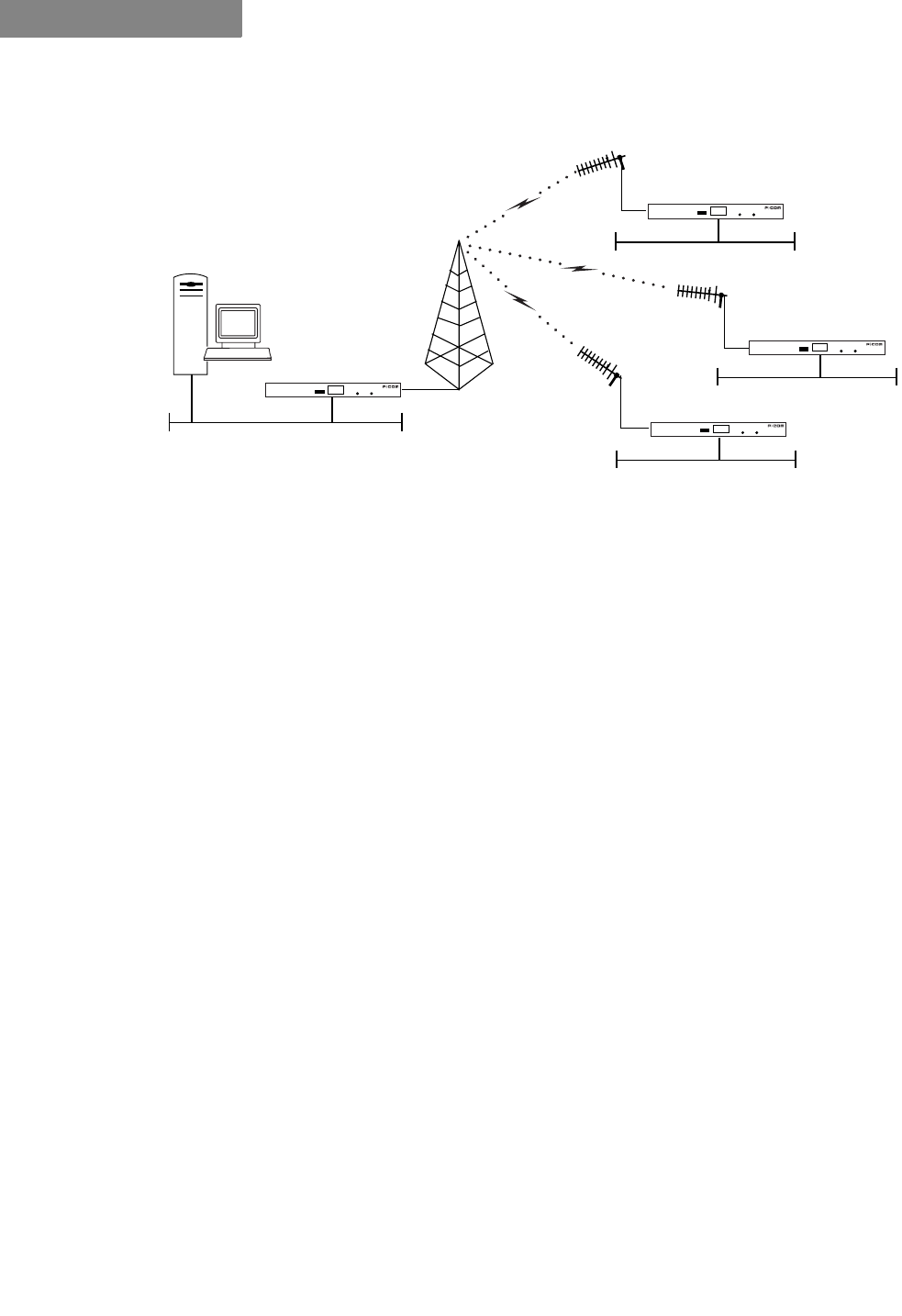
&(175$/,=('67$57232/2*<
In a Star topology, there is one radio at a central location
designated as a Base Station or Star Base, and several remotes
designated as Remote Stations or Star Remotes. The Star Base acts
as a switching device. The Star Remotes communicate with each
other through the Star Base.
A DataMetro II wireless network with centralized topology can
connect up to 127 wireless nodes. The MAC protocol used is a
combination of random and polling MAC protocols, with
positive Data Link acknowledgment that improves the reliability
of frame delivery.
Figure 2-3 on page 2-4 shows DataMetro II wireless router nodes
in a star topology.
DATAMETRO II DATAMETRO II
Ethernet Ethernet
DATAMETRO II
Ethernet
WIRELESS NETWORK DESIGN
Centralized (Star) Topology
2-4 P-Com DataMetro II
2
Figure 2-3 Star Topology
A directional antenna can be used for the central site if all of the
nodes fall in the main lobe of the antenna pattern. Since the
remote sites need only communicate with the central site,
directional, high gain antennas can be used.
The range of a Star topology network can be increased if the
remote nodes are all located within a confined sector from the
central site. Communication between two remote sites must be
relayed through the central node.
Medium access contention on the Star Base is resolved by the
specific Star Base MAC protocol. The Star Remote sends the data
frame only when it gets permission from the Star Base. Each
frame regularly transmitted by the Star Base contains the PID
(polling ID) of the wireless cluster node. If a polled Star Remote
has a frame to transmit, it explicitly sends the frame to the Star
Base. The Star Base relays this frame to the Star Remotes
indicated by the DID (destination ID) of the original frame. A
polled Star Remote does not reply on the PID if it has no frame to
transmit.
DATAMETRO II
DATAMETRO II
DATAMETRO II
DATAMETRO II
BASE STATION REMOTE STATIONS
Ethernet
Ethernet
Ethernet
Ethernet

Hardware Installation Guide 3-1
3
. . . . .
. . . . . . . . . . . . . . . . . . . . . . . . . . . . . . . . . . .
+
$5':$5(
,
167$//$7,21
At each wireless node, the P-Com DataMetro II radio connects to
a LAN, where it functions as a wireless remote access router,
connecting the LAN into the wireless WAN (wide area network).
Each radio is shipped in a carton that contains:
• one P-Com DataMetro II wireless router
• 0 dbi test antenna
• AC power cord
• mounting brackets and hardware for optional rack mounting
•Site Manager application diskettes
• P-Com DataMetro II Installation Guide
• P-Com DataMetro II Administrator’s Guide
. . . . . . . . . . . . . . . . . . . . . . . . . . . . . . . . . . . . . . . . . . . . . . . . . .
:,5(/(665287(5,167$//$7,21
Once you have set basic configuration parameters for the
DataMetro II unit, you can install the router in the network. You
provide power for the radio by connecting the AC power cord.
Before making any cable connections, however, you need to
ground the unit.
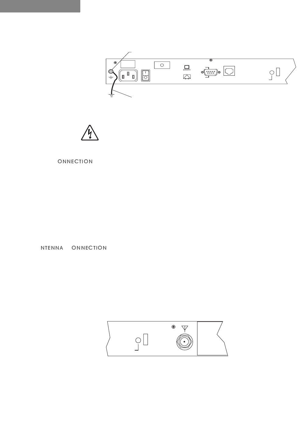
*5281'&211(&7,21
7RJURXQGWKH'DWD0HWUR,,UDGLR
1/RRVHQWKH*1'QXWRQWKHEDFNRIWKHUDGLR
2$WWDFKD$:*PLQLPXPZLUHIURPWKHJURXQGLQJVWXGWRDVDIH
JURXQG6HH)LJXUH
HARDWARE INSTALLATION
Wireless Router Installation
3-2 P-Com DataMetro II
3
Figure 3-1 Attaching the Ground Wire to the Radio
7KH3&RP'DWD0HWUR,,UDGLRVKRXOGEHJURXQGHGDWWKHJURXQGQXW
RQWKHEDFNRIWKHUDGLREHIRUH\RXFRQQHFWDQ\RWKHUFDEOHVWRWKH
UDGLR$IWHUWKHUDGLRLVJURXQGHGPDNHVXUHWKDWDQ\RWKHU
HTXLSPHQWWKDW\RXFRQQHFWWRWKHUDGLRLVDOVRSURSHUO\JURXQGHG
/$1&
7RFRQQHFWWKH'DWD0HWUR,,UDGLRWRWKH/$1
13OXJRQHHQGRIDQ5-FDEOHLQWRWKH5-(WKHUQHWSRUWRQWKH
EDFNRIWKHUDGLR
23OXJWKHRWKHUHQGRIWKH5-FDEOHLQWRWKH5-SRUWRQWKH
(WKHUQHW+XE
,I\RXDUHFRQQHFWLQJWKHUDGLRGLUHFWO\WRD3&XVHDFURVVRYHUFDEOH
SOXJRQHHQGLQWRWKH5-SRUWRQWKHUDGLRDQGWKHRWKHUHQGLQWR
WKH5-SRUWRIWKH(WKHUQHWFDUG
$&
The type of antenna you use should be a semi-parabolic or solid
parabolic directional antenna. You can purchase the antenna from
P-Com or its distributors.
The indoor antenna connects to the rear of the DataMetro II unit
through the N-type connector labeled $17 on the back of the
radio. See Figure 3-2. The outdoor antenna is connected through
coaxial cable.
Figure 3-2 ANT Connector
7RFRQQHFWDQLQGRRUDQWHQQDWRWKH'DWD0HWUR,,UDGLR
13OXJWKHDQWHQQDFRQQHFWRUILUPO\LQWRWKH1W\SHDQWHQQDFRQQHFWRU
RQWKHEDFNRIWKHXQLW
2+DQGWLJKWHQWKHFRQQHFWRUVKHOORQWRWKHMDFNFRQQHFWRUFROODU
Ground Wire
3/8" Hex Nut
GND
POWER
RESET
COM1
MODEM
TERMINAL
ETHERNET
U
L
127(
✐
ANT
POWER
REBOOT
FCC ID: G83AIRLINK
CYLINK CORPORA
. . . . .
HARDWARE INSTALLATION
Telephone Modem Connection
Hardware Installation Guide 3-3
39HULI\WKDWWKHFRQQHFWRULVIL[HGILUPO\LQSODFH
7RFRQQHFWDQRXWGRRUDQWHQQDWRWKH'DWD0HWUR,,UDGLR
13OXJWKHFRD[LDODQWHQQDFDEOHLQWRWKH1W\SHDQWHQQDFRQQHFWRURQ
WKHEDFNRIWKHXQLW
2+DQGWLJKWHQWKHFRQQHFWRUVKHOORQWRWKHMDFNFRQQHFWRUFROODU
39HULI\WKDWWKHFDEOHLVIL[HGILUPO\LQSODFH
,IWKHDQWHQQDFRD[LDOFDEOHLVWRRVWLIIWREHQGHDVLO\DGGDIOH[LEOH
SLJWDLOFRD[LDOFDEOHZLWKDFRD[EDUUHODYDLODEOHIURP3&RP
3&
7RFRQQHFWSRZHUWRWKH'DWD0HWUR,,UDGLR
13OXJWKH$&SRZHUFRUGLQWRWKHSLQFRQQHFWRURQWKHEDFNRIWKH
UDGLR6HH)LJXUHRQSDJH
23OXJWKH$&SRZHUFRUGLQWRDJURXQGHGHOHFWULFDORXWOHW
7RDYRLGHOHFWULFDOVKRFNRUSRZHUORVVHQVXUHWKDWWKHSRZHUFRUGLV
VHFXUHO\FRQQHFWHGWRWKHXQLW'RQRWXVHDSROHWRSROHDGDSWHU
ZLWKWKHSOXJ9HULI\WKDWWKHRXWOHW\RXLQWHQGWRXVHLVSURSHUO\LQVWDOOHG
DQGJURXQGHGWKHRXWOHWXVHGPXVWFRPSO\ZLWKWKHORFDOHOHFWULFDO
FRGHIRU\RXUFRXQWU\
37XUQWKH$&SRZHUVZLWFKWR216HH)LJXUHRQSDJH
. . . . . . . . . . . . . . . . . . . . . . . . . . . . . . . . . . . . . . . . . . . . . . . . . .
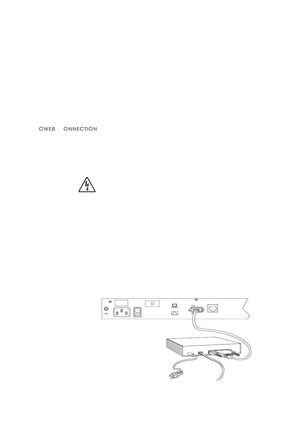
7(/(3+21(02'(0&211(&7,21
You can configure the P-Com DataMetro II wireless router
remotely by using a telephone modem and the public telephone
network. The DataMetro II provides an RS-232 port on the back
for the modem connection. See Figure 3-3.
Figure 3-3 Telephone Modem Connection
127(
✐
GND
RESET
COM1
MODEM
TERMINAL
ETHERNET
U
L
Telephone Modem
Phone Line
Power Supply

HARDWARE INSTALLATION
Basic Configuration Setup
3-4 P-Com DataMetro II
3
Telephone modems should be Hayes compatible modems, 9600
bps or faster. Refer to the modem documentation for the specific
baud rate, and for other modem configuration parameters.
7RFRQQHFWWKHWHOHSKRQHPRGHPWRWKH'DWD0HWUR,,
&RQQHFWWKHWHOHSKRQHPRGHPWRWKH56SRUWRQWKHEDFNRIWKH
'DWD0HWUR,,6HH)LJXUHRQSDJH
8VHDVWDQGDUG56PRGHPFDEOHZLWKDIHPDOH'%FRQQHFWRU
DWWKHUDGLRHQGDQGDQDSSURSULDWHFRQQHFWRUDWWKHPRGHPHQG
7RFRQQHFWWKHWHOHSKRQHPRGHPWRWKHWHUPLQDO
1&RQQHFWWKHFRPSXWHURUWHUPLQDOWRWKHWHOHSKRQHPRGHPXVLQJD
VWDQGDUG56PRGHPFDEOH
2&RQQHFWWKHWHOHSKRQHPRGHPWRWKHSKRQHOLQHXVLQJDQ
DSSURSULDWHFDEOH
. . . . . . . . . . . . . . . . . . . . . . . . . . . . . . . . . . . . . . . . . . . . . . . . . .
%$6,&&21),*85$7,216(783
Before you use a Data Metro II radio on the WAN, P-Com
recommends that you set up a basic radio configuration to make
sure the full WAN installation will proceed smoothly.
The basic configuration requires
• RF channel—all units in the WAN must use the same RF
channel. Separate WANs in the same geographic area may
need to use different channels. The DataMetro II Model 1280
provides nine channels; the Model 320 provides 14 channels.
• PN code—all units in the WAN must use the same PN code.
Different PN code sequences reduce interchannel and co-
channel interference between networks. The DataMetro II
provides eight PN codes.
• topology—the Data Metro II provides these topologies: peer-
to-peer, point-to-point, centralized (star base and star remote)
• reboot—to install the basic configuration
You can set up a basic radio configuration through one of three
methods:
• through twelve DIP switch positions
• through a terminal command line interface
• through the Site Manager software application
. . . . .
HARDWARE INSTALLATION
Basic Configuration Setup
Hardware Installation Guide 3-5
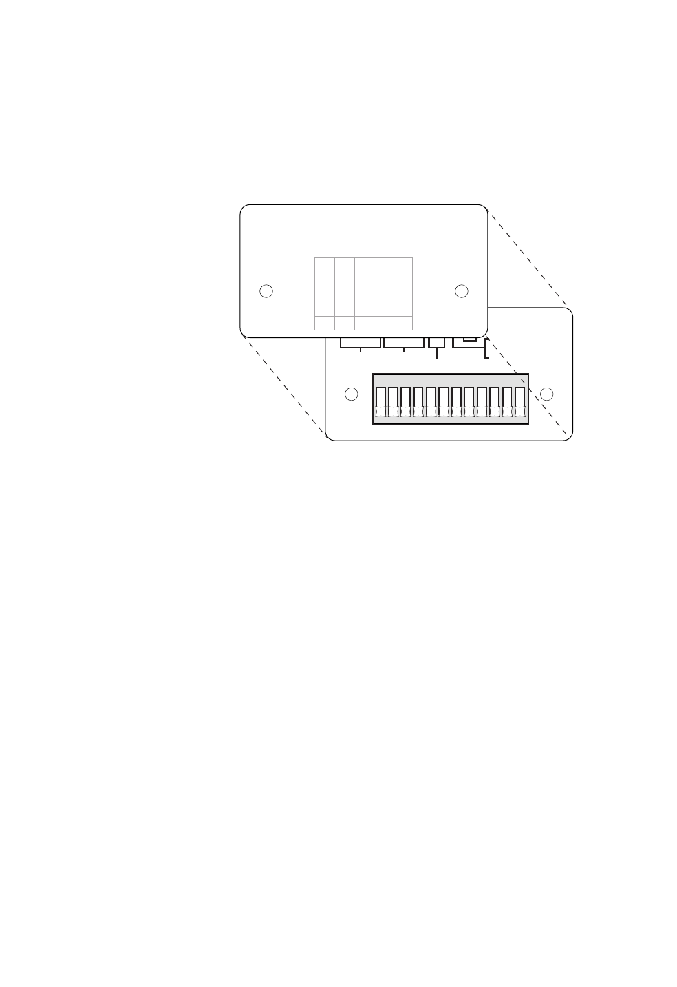
',36:,7&+(6
The P-Com Data Metro II radio can be configured through a block
of twelve OFF/ON switches (DIP switches) located on the front
of the radio behind the switch plate. See Figure 3-4.
Figure 3-4 DIP Switches
7RVHWWKHVZLWFKWRWKH21SRVLWLRQSXVKWKHVZLWFKXSWRZDUGWKHWRS
RIWKHUDGLR
7RVHWWKHVZLWFKWRWKH2))SRVLWLRQSXVKWKHVZLWFKGRZQWRZDUGWKH
ERWWRPRIWKHUDGLR
7RVHWXSDEDVLFUDGLRFRQILJXUDWLRQXVLQJWKH',3VZLWFKHV
15HPRYHWKHUDGLRIURPWKHVKLSSLQJFDUWRQ
23ODFHWKHUDGLRRQDIODWVXUIDFHVRWKDWWKHIURQWRIWKHUDGLRLVHDV\WR
UHDFK
35HPRYHWKHVZLWFKSODWHIURPWKHIURQWRIWKHUDGLR
46HWWKH',3VZLWFKHVIRUWKH5)FKDQQHOWKH31FRGHDQGWKHWRSRORJ\
5HIHUWR7DEOHVWKURXJK
123456789101112
O
N
ON-CONFIGURATION RESET
RF CHANNEL PN-CODE SEE COVER LABEL
ON-ANTENNA ALIGNMENT
MODE
OFF-NORMAL MODE
1
1
2
2
34
4
5678
812
48
9101112
RF CHANNEL AND PN CODE MUST BE SELECTED USING
BINARY FORMAT (1 - ON, 0 - OFF)
TO CONFIGURE BY SOFTWARE OR TERMINAL ALL 12
SWITCHES MUST BE OFF
STAR REMOTE
STAR BASE
PEER-TO-PEER
POINT-TO-POINT
TOPOLOGY
ON
OFF
ON
OFF
ON
ON
OFF
OFF
109

HARDWARE INSTALLATION
Basic Configuration Setup
3-6 P-Com DataMetro II
3
6HWWKH5)FKDQQHOVZLWFKHVDFFRUGLQJWR7DEOH 1RWHWKDW
&KDQQHOVWKURXJKDUHDYDLODEOHRQO\IRUWKH0RGHO
6HWWKH31FRGHDFFRUGLQJWR7DEOH
Table 3-1 RF Channel Switch Positions
Channel
Switch
1234
1 OFF OFF OFF ON
Model
1280
and
Model
320
2 OFF OFF ON OFF
3OFFOFFONON
4 OFF ON OFF OFF
5OFFONOFFON
6 OFF ON ON OFF
7 OFF ON ON ON
8 ON OFF OFF OFF
9ONOFFOFFON
10 ON OFF ON OFF
Model
320
only
11 ON OFF ON ON
12 ON ON OFF OFF
13 ON ON OFF ON
14 ON ON ON OFF
Table 3-2 PN Code Switch Positions
PN
Code
Switch
5678
1 OFF OFF OFF ON
2 OFF OFF ON OFF
3OFFOFFONON
4 OFF ON OFF OFF
5 OFF ON OFF ON
6 OFF ON ON OFF
7 OFF ON ON ON
8 ON OFF OFF OFF

. . . . .
HARDWARE INSTALLATION
Basic Configuration Setup
Hardware Installation Guide 3-7
6HWWKHWRSRORJ\DFFRUGLQJWR7DEOH
56HW6ZLWFK³$QWHQQD$OLJQPHQWWR2))
66HW6ZLWFK³5HVHW&RQILJXUDWLRQWR2))
:KHQ\RXPRYHWKH'DWD0HWUR,,XQLWIURPRQHQHWZRUNWRDQRWKHU\RX
ZLOOQHHGWRUHVHWWKHPRYHGXQLW·VFRQILJXUDWLRQE\VHWWLQJVZLWFKWR
21
&200$1'/,1(,17(5)$&(
The P-Com Data Metro II radio can be configured through a
command line interface running on a terminal (or a PC running a
terminal emulation program).
Before connecting the terminal to the radio, configure the
terminal with the following settings:
• Baud rate = 9600
•Data bits = 8
• Parity = None
• Stop bits = 1
• Flow control = Hardware
If you are using a PC or laptop computer, refer to the operating
system documentation for instructions on how to configure and
run the terminal emulation program.
7RVHWXSWKHUDGLR
15HPRYHWKHUDGLRIURPWKHVKLSSLQJFDUWRQ
25HPRYHWKHVZLWFKSODWHIURPWKHIURQWRIWKHUDGLR6HH)LJXUHRQ
SDJH
30DNHVXUH$//WKH',3VZLWFKHVRQWKHIURQWRIWKHUDGLRDUHLQWKH2))
SRVLWLRQ7KLVLVWKHPDQXIDFWXULQJGHIDXOW
7RVHWWKHVZLWFKWRWKH2))SRVLWLRQSXVKWKHVZLWFKGRZQWRZDUGWKH
ERWWRPRIWKHUDGLR
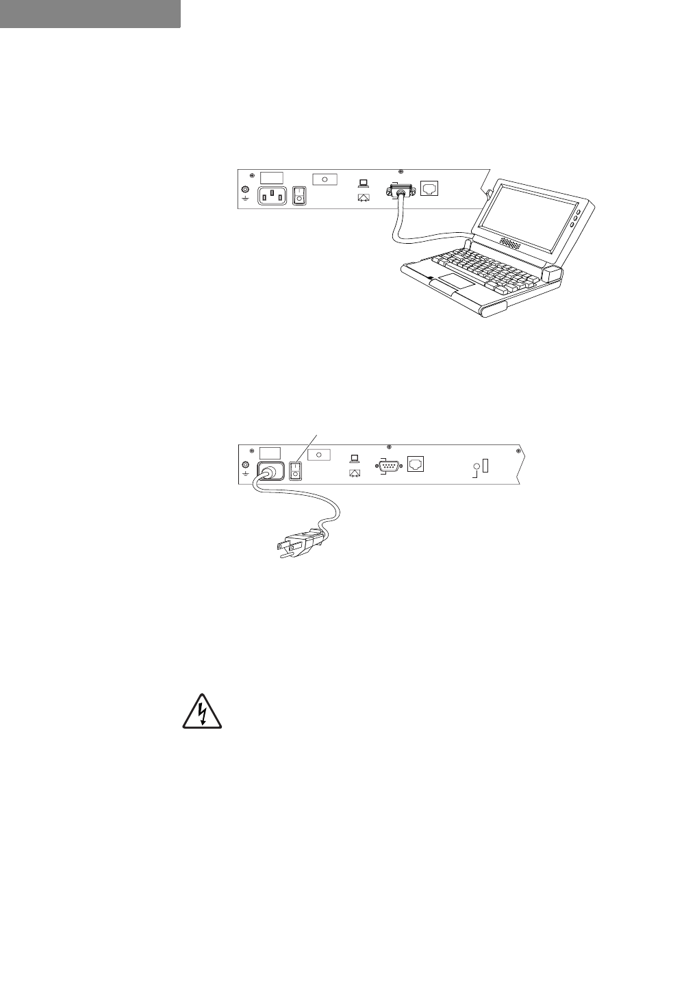
4&RQQHFWWKHWHUPLQDORU3&WRWKH'%56FRQQHFWRURQWKHEDFN
RIWKHUDGLR6HH)LJXUHRQSDJH
Table 3-3 Topology Switch Positions
Switch
Topology 910
Star Remote ON ON
Star Base ON OFF
Peer-to-Peer OFF ON
Point-to-Point OFF OFF
127(
✐
HARDWARE INSTALLATION
Basic Configuration Setup
3-8 P-Com DataMetro II
3
8VHDFURVVRYHUQXOOPRGHPFDEOHZLWKD'%PDOHFRQQHFWRURQ
RQHHQGWRFRQQHFWWRWKHUDGLRDQGDQDSSURSULDWHFRQQHFWRUDWWKH
FRPSXWHUHQG
Figure 3-5 Connecting the Terminal or PC
57XUQRQWKHWHUPLQDORUFRPSXWHUDQGVWDUWWKHWHUPLQDOVHVVLRQ
6&RQQHFWSRZHUWRWKH'DWD0HWUR,,XQLW6HH)LJXUH
Figure 3-6 Connecting the Power Cord
3OXJWKH$&SRZHUFRUGLQWRWKHSLQFRQQHFWRURQWKHEDFNRIWKH
UDGLR
3OXJWKHSURQJHQGRIWKH$&SRZHUFRUGLQWRDJURXQGHGHOHFWULFDO
RXWOHW
7RDYRLGHOHFWULFDOVKRFNRUSRZHUORVVHQVXUHWKDWWKHSRZHUFRUGLV
VHFXUHO\FRQQHFWHGWRWKHXQLW'RQRWXVHDSROHWRSROHDGDSWHU
ZLWKWKHSOXJ9HULI\WKDWWKHRXWOHW\RXLQWHQGWRXVHLVSURSHUO\LQVWDOOHG
DQGJURXQGHGWKHRXWOHWXVHGPXVWFRPSO\ZLWKWKHORFDOHOHFWULFDO
FRGHIRU\RXUFRXQWU\
7XUQWKH$&SRZHUVZLWFKWR216HH)LJXUH
After power-on the unit will run a power-on-self-test (POST).
This test takes about 40 seconds to complete. Successful
completion of the POST causes the 7-bank LEDs on the front of
the radio to flicker before going to a steady state.
If you have successfully connected to the radio, the terminal will
display the 'DWD0HWUR! prompt and an initial message.
GND
RESET
COM1
MODEM
TERMINAL
ETHERNET
U
L
GND
POWER
RESET
COM1
MODEM
TERMINAL
ETHERNET
U
L
AC Power Cord
AC Power
On/Off Switch
(| = On, O = Off)

. . . . .
HARDWARE INSTALLATION
Basic Configuration Setup
Hardware Installation Guide 3-9
7RFRQILJXUHEDVLFUDGLRFRQILJXUDWLRQSDUDPHWHUV
1&RQILJXUHWKHUDGLR
6HWWKHWRSRORJ\$WWKHSURPSWW\SH73/*Q!
ZKHUHQ! 6WDU5HPRWH6WDU%DVH3HHUWR3HHURU
3RLQWWR3RLQW
6HWWKH5)FKDQQHO$WWKHSURPSWW\SH5)Q!
ZKHUHQ! WKURXJKIRU0RGHOWKURXJKIRU0RGHO
6HWWKH31FRGH$WWKHSURPSWW\SH316Q!
ZKHUHQ! WKURXJK
2237,21$/&KHFN\RXUVHWWLQJV$WWKHSURPSWW\SH,1)27KHWHUPLQDO
ZLOOGLVSOD\LQIRUPDWLRQVLPLODUWRWKHIROORZLQJ
'DWD0HWUR,,6HWXS&RQILJXUDWLRQ
(WKHUQHW0$&$GGUHVV;;;;;;;;;;;;
7RSRORJ\6WDU5HPRWHZDVVHOHFWHG3RLQWWR3RLQWQRZVHOHFWHG
5)&KDQQHOZDVVHOHFWHG QRZVHOHFWHG
31&RGHZDVVHOHFWHG QRZVHOHFWHG
,3$GGUHVV
3&RQILUP\RXUVHWWLQJVE\UHVHWWLQJWKHFRQILJXUDWLRQ
2QWKHEDFNRIWKHUDGLRSXVKWKH5(%227EXWWRQ
$WWKHSURPSWW\SH,1)27KLVGLVSOD\VWKHFRQILJXUDWLRQ\RXVHWLQ
6WHS
'DWD0HWUR,,6HWXS&RQILJXUDWLRQ
(WKHUQHW0$&$GGUHVV;;;;;;;;;;;;
7RSRORJ\3RLQWWR3RLQW
5)&KDQQHO
31&RGH
,3$GGUHVV
6,7(0$1$*(5$33/,&$7,21
The P-Com Data Metro II radio can be configured through a
Windows-based software application call Site Manager.
Site Manager runs on an external computer connected remotely
to the DataMetro II unit over the LAN through the Ethernet port,
or over the public telephone network through the RS-232 port.
Site Manager is generally used by the network administrator for
both basic configuration of a DataMetro II unit as well as
advanced configuration of a wireless cluster of units. If you want
*In the example, XXXXXXXXXXXX is factory set and is unique to each radio.
This MAC address cannot be changed.

HARDWARE INSTALLATION
Basic Configuration Setup
3-10 P-Com DataMetro II
3
to set up the basic configuration using Site Manager, see the
Administrator’s Reference. It will tell you how to install the
application, and how to use it.
Hardware Installation Guide 4-1
4
. . . . .
. . . . . . . . . . . . . . . . . . . . . . . . . . . . . . . . . . .
5
$&.
0
2817,1*
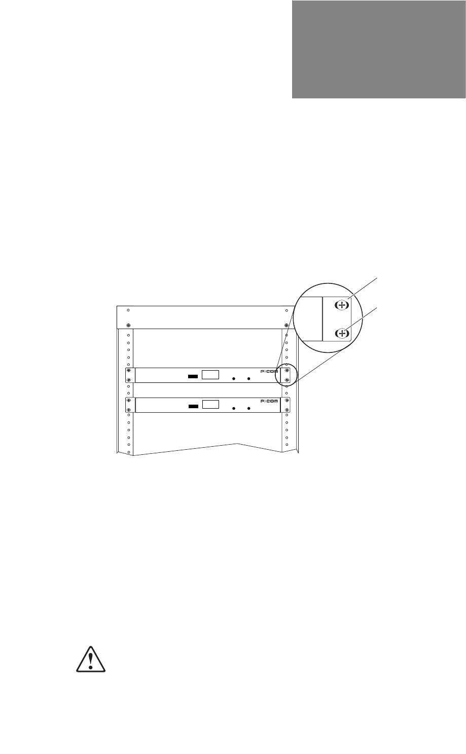
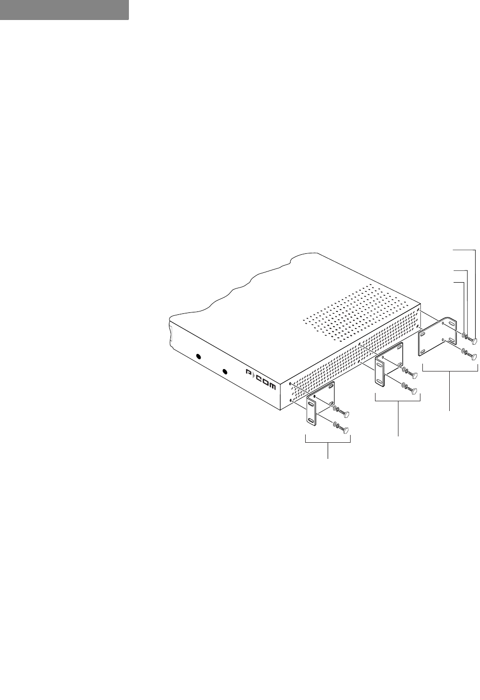
Figure 4-1 Rack Mounted Radios
The P-Com DataMetro II radio can be mounted in a standard
19 inch or 23 inch equipment rack using brackets and hardware
provided with the radio. See Figure 4-1.
The rack mounting brackets can be installed on the radio chassis
in one of three positions: front, center, or rear, depending on how
you want the chassis positioned in the rack.
For a 19 inch rack, the short bracket flanges face the front of the
radio. See Figure 4-2 on page 4-2. For a 23 inch rack, the longer
bracket flanges face the front of the radio. See Figure 4-3 on page
4-3.
:KHQLQVWDOOLQJWKHUDGLRLQDUDFNZLWKRWKHUHTXLSPHQW\RXPXVW
SURYLGHLQFKHVRIVSDFHDERYHEHORZDQGRQHDFKVLGHRIWKH
UDGLRWRDOORZIRUSURSHUYHQWLODWLRQ
Front Flange
Screws
(Supplied by
Customer)
DATAMETRO II
RSQ SYNC POWER
DATAMETRO II
RSQ SYNC POWER
RACK MOUNTING
4-2 P-Com DataMetro II
4
To mount the radio in a rack, you need:
• two rack-mount brackets (supplied)
• screws and washers to attach the brackets to the radio
(supplied)
• 1/4 inch hex nut driver or wrench
• screwdriver
,1&+5$&.02817
Refer to Figure 4-2 when mounting the radio in a 19 inch
equipment rack.
Figure 4-2 Brackets for 19 inch Rack Mount
7RPRXQWWKHUDGLRLQDLQFKUDFN
1&KRRVHWKHIURQWFHQWHURUUHDUUDFNPRXQWSRVLWLRQIRUWKHUDGLR
23ODFHDEUDFNHWRQWKHFKDVVLVLQWKHFKRVHQSRVLWLRQVRWKDWWKH
EUDFNHWKROHVOLQHXSZLWKWKHWKUHDGHGLQVHUWVRQWKHVLGHRIWKH
FKDVVLVDQGWKHVKRUWIODQJHIDFHVWKHIURQWRIWKHUDGLRIRUWKHIURQWRU
FHQWHUSRVLWLRQPRXQWRUWKHEDFNRIWKHUDGLRIRUWKHUHDUSRVLWLRQ
PRXQW
3$WWDFKWKHEUDFNHWWRWKHFKDVVLV
8VHWZRRIWKHVFUHZVORFNZDVKHUVDQGIODWZDVKHUVVXSSOLHGZLWKWKH
UDGLR
Front
Position
Center
Position
Rear
Position
Flat Washer
Lock Washer
Hex Head Screw
6-32 x 3/8 inch
SYNC POWER
. . . . .
RACK MOUNTING
Hardware Installation Guide 4-3
45HSHDW6WHSDQG6WHSWRDWWDFKDQRWKHUEUDFNHWRQWKHRSSRVLWH
VLGHRIWKHFKDVVLV
5$WWDFKWKHEUDFNHWHGFKDVVLVWRWKHUDFNSRVWV5HIHUWR)LJXUHRQ
SDJH
$OLJQWKHIURQWIODQJHVRIWKHEUDFNHWVZLWKWKHVFUHZKROHVRQWKHUDFN
SRVWV
+DQGWLJKWHQWKHPRXQWLQJVFUHZVWRKROGWKHUDGLRDQGEUDFNHWVLQ
SODFHRQWKHUDFNSRVWV
8VHDVFUHZGULYHUWRILUPO\DWWDFKWKHUDGLRWRWKHUDFNSRVWV
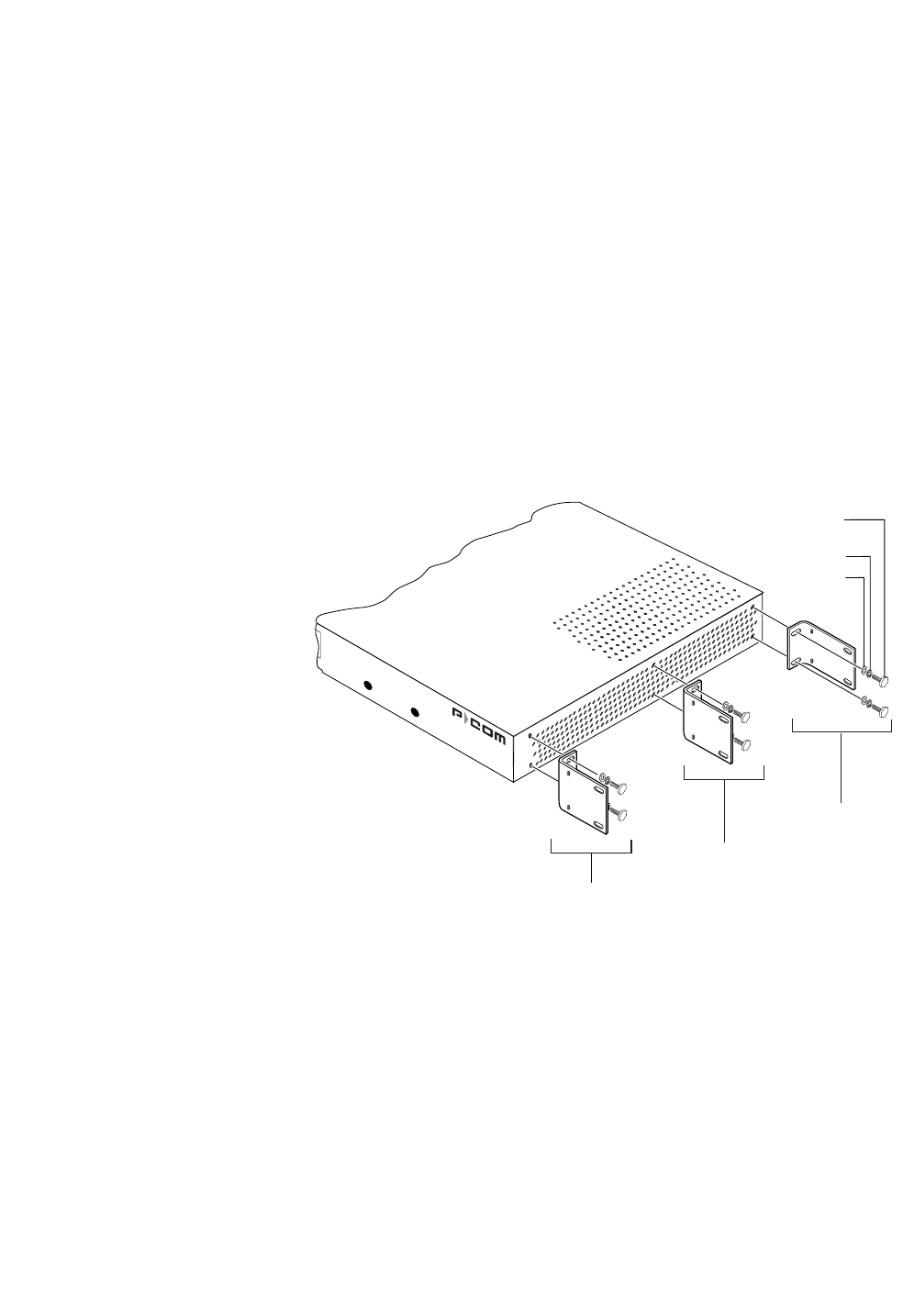
,1&+5$&.02817
Refer to Figure 4-3 when mounting the radio in a 23 inch
equipment rack.
Figure 4-3 Brackets for 23 inch Rack Mount
7RPRXQWWKHUDGLRLQDLQFKUDFN
1&KRRVHWKHIURQWFHQWHURUUHDUUDFNPRXQWSRVLWLRQIRUWKHUDGLR
23ODFHDEUDFNHWRQWKHFKDVVLVLQWKHFKRVHQSRVLWLRQVRWKDWWKH
EUDFNHWKROHVOLQHXSZLWKWKHWKUHDGHGLQVHUWVRQWKHVLGHRIWKH
FKDVVLVDQGWKHVKRUWIODQJHIDFHVWKHIURQWRIWKHUDGLRIRUWKHIURQWRU
FHQWHUSRVLWLRQPRXQWRUWKHEDFNRIWKHUDGLRIRUWKHUHDUSRVLWLRQ
PRXQW
3$WWDFKWKHEUDFNHWWRWKHFKDVVLV
8VHWZRRIWKHVFUHZVORFNZDVKHUVDQGIODWZDVKHUVVXSSOLHGZLWKWKH
UDGLR
Front
Position
Center
Position
Rear
Position
Flat Washer
Lock Washer
Hex Head Screw
6-32 x 3/8 inch
SYNC POWER

RACK MOUNTING
4-4 P-Com DataMetro II
4
45HSHDW6WHSDQG6WHSWRDWWDFKDQRWKHUEUDFNHWRQWKHRSSRVLWH
VLGHRIWKHFKDVVLV
5$WWDFKWKHEUDFNHWHGFKDVVLVWRWKHUDFNSRVWV5HIHUWR)LJXUHRQ
SDJH
$OLJQWKHIURQWIODQJHVRIWKHEUDFNHWVZLWKWKHVFUHZKROHVRQWKHUDFN
SRVWV
+DQGWLJKWHQWKHPRXQWLQJVFUHZVWRKROGWKHUDGLRDQGEUDFNHWVLQ
SODFHRQWKHUDFNSRVWV
8VHDVFUHZGULYHUWRILUPO\DWWDFKWKHUDGLRWRWKHUDFNSRVWV

Hardware Installation Guide A-1
A
. . . . .
. . . . . . . . . . . . . . . . . . . . . . . . . . . . . . . . . . .
6
3(&,),&$7,216
. . . . . . . . . . . . . . . . . . . . . . . . . . . . . . . . . . . . . . . . . . . . . . . . . .
<($5&203/,$1&(
Wireless radios manufactured by P-Com, Inc. have been tested
and found to be Year 2000 compliant. The test script and test
results are filed with the product verification records and can be
made available on request. P-Com, Inc. design procedures
require all future updates or new product offerings to meet Year
2000 compliance and to be verified by testing.
A compliant product accurately processes date data from, into
and between the 20th and 21st centuries, the years 1999 and 2000,
and leap year calculations, when used in accordance with its
product documentation, and provided all other products used in
combination with the product properly exchange data with it.
SPECIFICATIONS
General Specifications
A-2 P-Com DataMetro II
A
. . . . . . . . . . . . . . . . . . . . . . . . . . . . . . . . . . . . . . . . . . . . . . . . . .
*(1(5$/63(&,),&$7,216
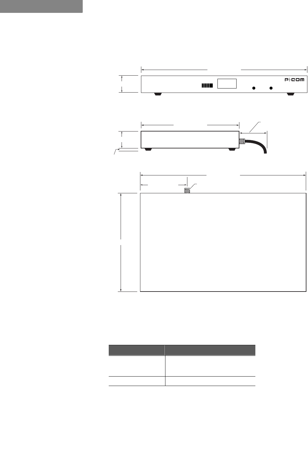
Figure A-1 Radio Dimensions
Table A-1 Mechanical Specifications
Parameter Specification
Dimensions Width: 17 inches (432 mm)
Height: 1.75 inches (44 mm)
Depth: 10 inches (254 mm)
Weight 10.3 pounds (4.7 kilograms)
front
1.75" (44 mm)
17" (432 mm)
4.55" (140 mm)
17" (432 mm)
1.75" (44 mm)
.5" (13 mm)
10" 254 mm)
10" (254 mm)
3" (76 mm)
minimum clearance
for pigtail antenna cable
Front View
Side View
Top View
Type "N"
Antenna Connector
DATAMETRO II
RSQ SYNC POWER
. . . . .
SPECIFICATIONS
General Specifications
Hardware Installation Guide A-3
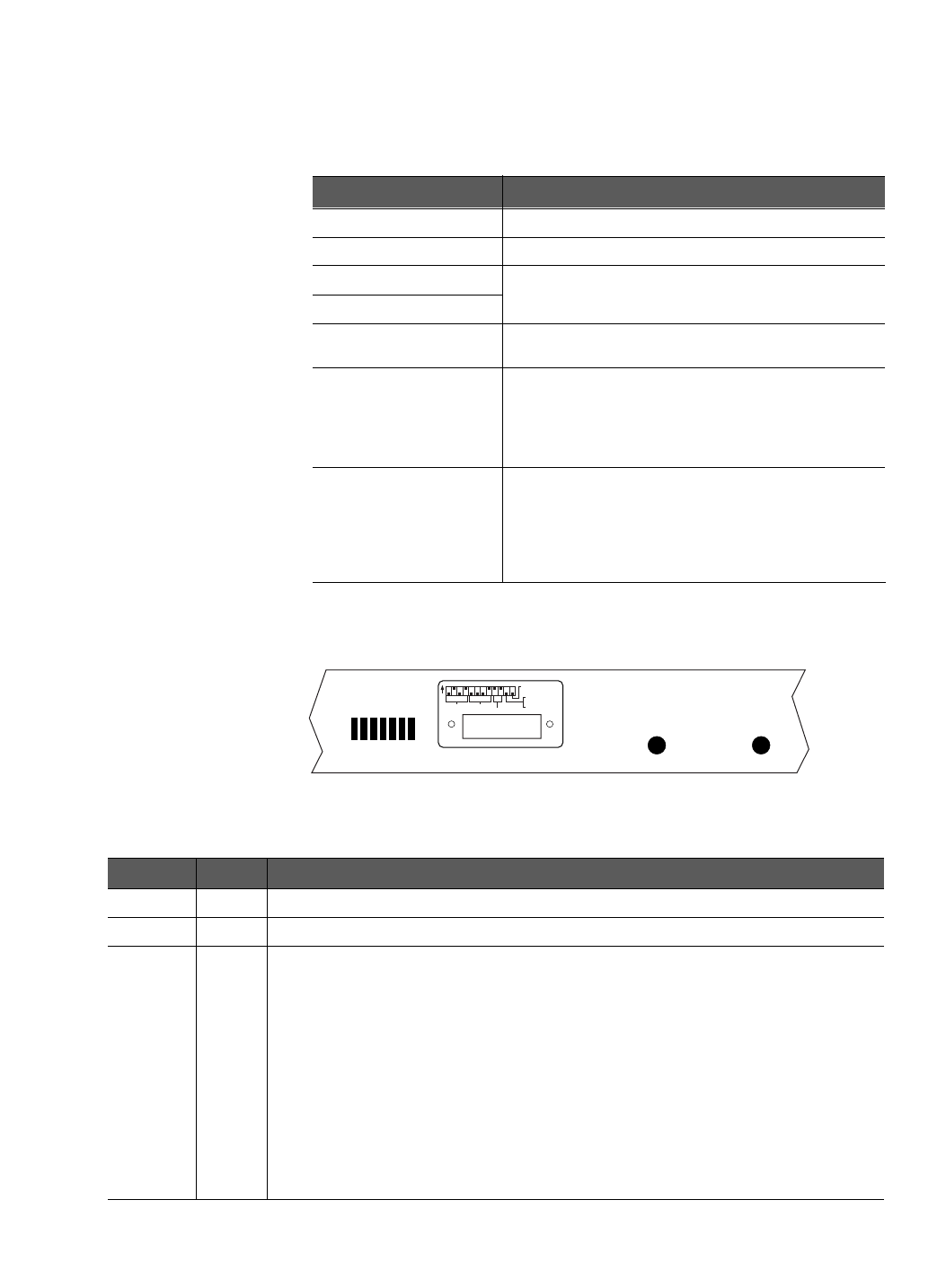
/(',1',&$7256
Figure A-2 Front Panel Indicators
Table A-2 Environment Specifications
Parameter Specification
Operating Temperature 0°C to 50°C (32°F to 122°F)
Storage Temperature –40°C to 66°C (–40°F to 150°F)
Operating Humidity 10% to 95% RH non-condensing
Storage Humidity
Elevation 200 feet (61 meters) below sea level to 13000 feet
(3943 meters) above sea level
Shock
Transportation/Handling Shock: Drop Test per NSTA
Project 2A
Operation Shock: Bellcore TR-TSY-000487, Section
5.1.4.9, Subsection IIA (Drop Tests for Unpacked
Housing Weighing 50 lb or less)
Vibration
Transportation Vibration: ASTM D 4728 Random
Vibration Testing Truck/Air Spectrum (1G, 5-200 Hz),
according to the general requirements of ASTM D
4728
Operational Vibration: Bellcore TR-TSY-000487,
Section 5.1.4.11 (Vibration Test-Low Level)
Table A-3 Front Panel Indicators
Name Color Function
32:(5 Yellow ON = power to the radio is on
6<1& Green ON = radio receiving data frame header
564 Green
Steady illumination of LEDs indicates the strongest/highest quality of the receive
signal.
Sequential illumination of all 7 LEDs indicates radio initialization self-test is in progress.
Blinking of all 7 LEDs in addition to audible alarm indicates Configuration Reset DIP
switch is ON and that the radio initial configuration and manufacturing image are
selected for next restart.
Blinking of the 1st of the 7 LEDs in addition to audible alarm indicates the wrong RF
channel is set on the DIP switches.
Blinking of the 2nd of the 7 LEDs in addition to audible alarm indicates the wrong PN
code is set on the DIP switches.
Blinking of the 3rd of the 7 LEDs in addition to audible alarm indicates that digital
board initialization has failed.
OFF while SYNC LED is illuminated indicates that the radio is not configured.
RSQ SYNC POWER
SPECIFICATIONS
General Specifications
A-4 P-Com DataMetro II
A
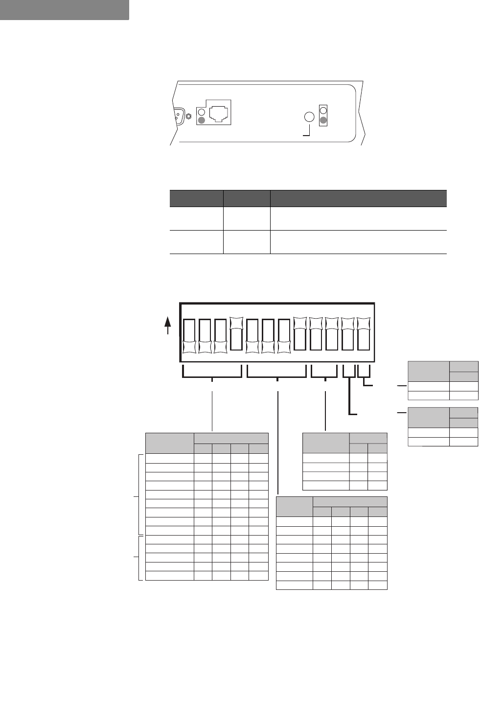
Figure A-3 Rear Panel Indicators
',36:,7&+(6
Figure A-4 DIP Switch Positions
$OO',3VZLWFKHVPXVWEHLQWKH2))SRVLWLRQZKHQXVLQJWKH&RPPDQG
/LQH,QWHUIDFHRU6LWH0DQDJHUDSSOLFDWLRQWRFRQILJXUHDUDGLR
Table A-4 Rear Panel Indicators
Name Color Function
(7+(51(7 Yellow
Green ON = no Ethernet activity
ON = radio is linked to LAN
32:(5 Yellow
Green ON = radio power is ON
non-functional
POWER
REBOOT
ETHERNET
123456789101112
O
N
RF CHANNEL
Switch
1
OFF
OFF
OFF
OFF
OFF
OFF
OFF
ON
ON
ON
ON
ON
ON
ON
OFF
OFF
OFF
ON
ON
ON
ON
OFF
OFF
OFF
OFF
ON
ON
ON
OFF
ON
ON
OFF
OFF
ON
ON
OFF
OFF
ON
ON
OFF
OFF
ON
ON
OFF
ON
OFF
ON
OFF
ON
OFF
ON
OFF
ON
OFF
ON
OFF
234
Channel
PN-CODE TOPOLOGY RESET
ANTENNA
ALIGNMENT
1
2
3
4
5
6
7
8
9
10
11
12
13
14
Switch
5
OFF
OFF
OFF
OFF
OFF
OFF
OFF
ON
OFF
OFF
OFF
ON
ON
ON
ON
OFF
OFF
ON
ON
OFF
OFF
ON
ON
OFF
ON
OFF
ON
OFF
ON
OFF
ON
OFF
678
PN
Code
1
2
3
4
5
6
7
8
Star Remote
Star Base
Peer-to-Peer
Point-to-Point
Switch
9
ON
ON
OFF
OFF
ON
OFF
ON
OFF
10
Topology
Yes
No
Switch
12
ON
OFF
Reset
Alignment
Normal
Switch
11
ON
OFF
Antenna
Alignment
Model
320
Only
Model
1280
and
Model
320
127(
✐
. . . . .
SPECIFICATIONS
General Specifications
Hardware Installation Guide A-5
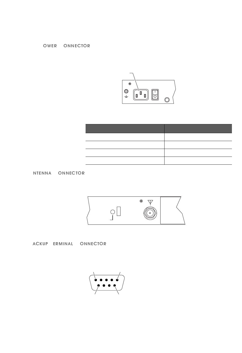
(;7(51$/&211(&7256
$&3 &
Connector Location: Rear Panel
Connector Type: 3-pin Male
Figure A-5 AC Power Connector
$&
Connector Location: Rear Panel
Connector Type: N-Type Female
Figure A-6 Antenna Connector
%7 &
Connector Location: Rear Panel
Connector Type: RS-232, DB 9-pin Male
Figure A-7 RS-232 Backup/Terminal Connector
Table A-5 Power Specifications
Parameter Specification
AC Input Voltage 90 VAC to 240 VAC
AC Input Frequency 47 Hz to 63 Hz
AC Input Current 1A to 3.5A
Maximum Power Consumption 32.25 Watts, AC Power Supply
GND
AC Power Connector
ANT
POWER
REBOOT
FCC ID: G83AIRLINK
CYLINK CORPORA
Pin 1 Pin 5
Pin 6 Pin 9
SPECIFICATIONS
General Specifications
A-6 P-Com DataMetro II
A
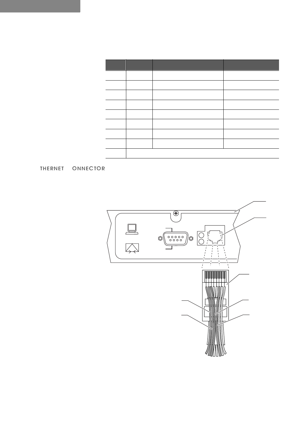
(&
Connector Location: Rear Panel
Connector Type: RJ-45 Jack
Figure A-8 Ethernet Jack
$Q\SLQQRWVKRZQLQ)LJXUH $LVQRWFRQQHFWHGLHSLQSLQ
SLQSLQ
Table A-6 RS-232 Port Pin Assignments
Pin Circuit Description Function
1 100 Received line signal detect from terminal
2 104 Received data from terminal
3 103 Transmitted data from radio
4 108/2 Data terminal ready from radio
5 102 Signal common circuit ground
6 107 Device ready from terminal
7 105 Request to send from radio
8 106 Clear to send from radio
9not used
12345678
Pin 1
TX+
Pin 2
TX–
Pin 3
RX+
COM1
MODEM
TERMINAL
ETHERNET
Rear Panel
RJ-45
10BaseT
Connector
RJ–45 Plug
(Hook Underneath)
Pin 6
RX–
127(
✐

. . . . .
SPECIFICATIONS
Radio Specifications
Hardware Installation Guide A-7
. . . . . . . . . . . . . . . . . . . . . . . . . . . . . . . . . . . . . . . . . . . . . . . . . .
5$',263(&,),&$7,216
Table A-7 Radio Specifications
Parameter Specification
Frequency Range 2400 GHz to 2483.5 GHz
Radio Technology Spread Spectrum using Direct Sequence
PN Sequence Length 32 bits
Modulation Technique BPSK
Channel Bandwidth Model 1280: 41.0 MHz
Model 320: 10.2 MHz
Sync Word Length 32 bits
Processing Gain 12 dB
Radio Protocol TDMA (Time Division Multiple Access)
Frequency Stability ±5 ppm
System Gain Model 1280: 115 dB
Model 320: 121 dB
Number of non-
overlapping channels Model 1280: 2
Model 320: 7
Table A-8 Transmitter Specifications
Parameter Specification
Load Impedance 50 ohms
Power Output 0 dBm to 28 dBm
Accuracy ±1 dB overall RF channel
±3 dB @ 0 dBm
±1 dB from 0°C to 50°C (32°F to 122°F)
Output Level Control 28 settings, 1 dBm increments
RF Port Protection None
Table A-9 Receiver Specifications
Parameter Specification
Sensitivity Model 1280: –86 dBm @ 10E-6 BER
Model 320: –92 dBm @ 10E-6 BER
Noise Figure 5 dB (RF LNA only)
Input Impedance 50 ohms
RF Input Protection None
Maximum RF Input Power –10 dBm
Dynamic Range 80 dB

SPECIFICATIONS
Center Frequencies
A-8 P-Com DataMetro II
A
. . . . . . . . . . . . . . . . . . . . . . . . . . . . . . . . . . . . . . . . . . . . . . . . . .
&(17(5)5(48(1&,(6
Table A-10 RF Channel Center Frequencies
Center
Frequency
(MHz) Model 320
RF Channel
Center
Frequency
(MHz) Model 1280
RF Channel
2407.068 1 2421.452 1
2412.268 2 2426.454 2
2417.465 3 2431.458 3
2422.665 4 2436.461 4
2427.863 5 2441.464 5
2433.063 6 2446.466 6
2438.261 7 2451.470 7
2443.461 8 2456.473 8
2448.658 9 2461.476 9
2453.858 10
2459.056 11
2464.256 12
2469.456 13
2474.653 14

Hardware Installation Guide Index-1
. . . . .
. . . . . . . . . . . . . . . . . . . . . . . . . . . . . . . . . . .
,
1'(;
1XPHULFV
19 inch rack mount 4-1, 4-2
23 inch rack mount 4-1, 4-3
$
antenna connection 3-8
antenna connector 1-3, A-5
autobaud process 3-6
%
backup connector A-5
basic configuration 3-2, 3-6
&
center frequencies A-8
Command Line Interface 1-1, 3-4
configuration
basic 3-1
'
DIP switches 1-1, 1-3, 3-2, 3-4,
A-4
(
Ethernet connector 1-3
Ethernet port 3-8
)
front panel 1-2, A-3
*
ground connection 3-8
grounding stud 1-3
/
LAN connection 3-8
0
modem configuration 3-9
1
network topologies
centralized 1-2, 2-3
configuration 3-1, 3-4, 3-6
peer-to-peer 1-2, 2-2
point-to-point 1-2, 2-2
range 2-4
star 1-2, 2-3
notes, cautions, and
warnings xiv
2
organization of Installation
Guide xiii
3
packet-based networks 2-1
pin assignments
RJ-45 A-6
RS-232 A-6
PN code 3-1, 3-3, 3-6
power connection 3-9
power connector 1-3, A-5
power indicator 1-3
power switch 1-3
product features 1-4
5
rack mount 4-1
radio dimensions A-2
rear panel 1-3
rear panel indicators A-4
reboot 3-1
RF channel 3-1, 3-3, 3-6, A-8
RJ-45 connector 1-3, 3-8, A-6
RS-232 connector A-5
RSQ 1-2
6
specifications
environment A-3
general A-2
mechanical A-2
radio A-7
radio weight A-2
receiver A-7
transmitter A-7
sync indicator 1-3
7
telephone modem 3-9, 3-10
terminal configuration 3-4
terminal connector A-5
terminal emulation program 3-4
terminal port 1-3
<
Year 2000 compliance A-1