Wavetrend Technologies LTG500 Tag SlimLine, L-TG500 User Manual
Wavetrend Technologies Limited Tag SlimLine, L-TG500
UserManual.wiki
>
Wavetrend Technologies
>
LTG500 User Manual
>
User Manual
Contents
1.
Product Information Sheet
2.
User Manual
3.
Users Guide
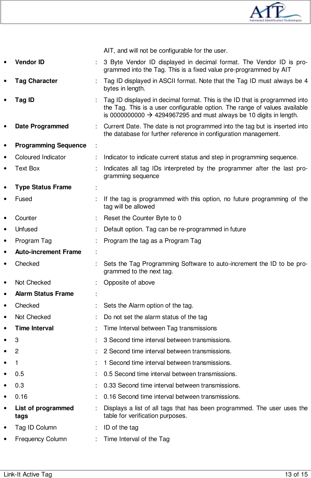
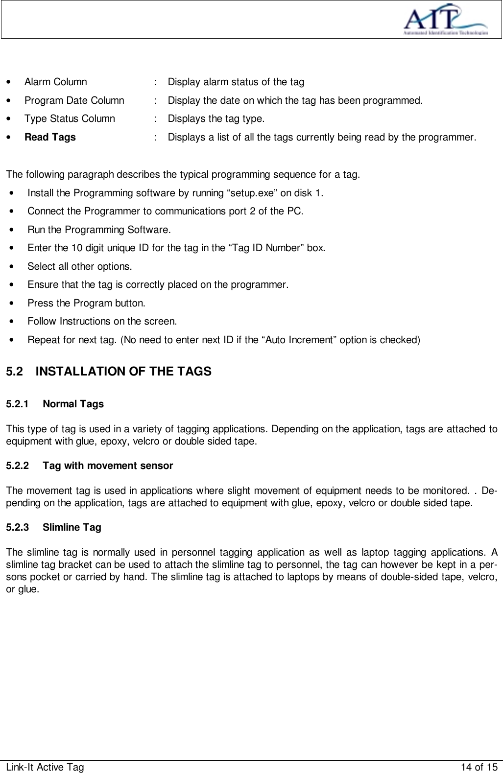
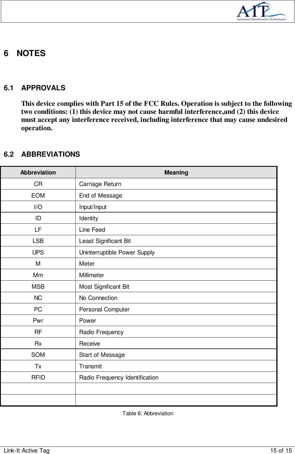
User Manual
Navigation menu
Upload a User Manual
Namespaces
Wiki Guide
HTML
PDF
Info
Views
User Manual
Discussion / Help
Navigation