Wavetrend Technologies LTG500 Tag SlimLine, L-TG500 User Manual
Wavetrend Technologies Limited Tag SlimLine, L-TG500
Contents
- 1. Product Information Sheet
- 2. User Manual
- 3. Users Guide
User Manual
Link-It Active Tag 1 of 15
User Manual for
the Link-It Active Tag
Document Number: AIT-PM-001
Client: General Product
Date: 22 August 2000
Issue: V1.0
Status: Final
Classification: Confidential
S/W File Name Tag User Manual
This document contains information relating to the patented rights of AIT. The confidentiality agreement
provisions are applicable to this document. When no longer needed for authorised purposes, this
document must be returned to AIT.
Link-It Active Tag 2 of 15
APPROVALS
Name Designation Signature Date
D. Bischoff Managing Director
T. Ashwin R&D Manager
K. Philips Operations Manager
D. Lategan Marketing Director
S. du Toit Technical Manager
Table 1: Approvals
AMENDMENT HISTORY
Issue Date Amendment Details Amended By
0.00 23 April 1999 Draft C.L. Neuhoff
1.00 22 August 00 FCC Approval H. Shrank
Table 2: Amendment History
REFERENCED DOCUMENTS
Number Title Date Rev Source
1. Info Sheet L-TG100 (Tag Information) AIT
Table 3: Referenced Documents

Link-It Active Tag 3 of 15
TABLE OF CONTENTS
1 SCOPE..................................................................................................................... 4
1.1 IDENTIFICATION.........................................................................................................................4
1.2 PRODUCT OVERVIEW ................................................................................................................4
1.3 DOCUMENT OVERVIEW..............................................................................................................4
2 PERFORMANCE PARAMETERS............................................................................. 6
2.1 OPERATIONAL DESCRIPTION....................................................................................................6
2.1.1 Tagging System....................................................................................................................6
2.1.2 Tags ....................................................................................................................................6
2.2 FUNCTIONAL CHARACTERISTICS...............................................................................................6
2.2.1 Tagging System....................................................................................................................6
2.2.2 Tags ....................................................................................................................................7
2.3 PHYSICAL CHARACTERISTICS ...................................................................................................7
2.3.1 Normal Tag and Tag with movement sensor............................................................................7
2.3.2 Slimline Tag..........................................................................................................................8
3 INTERFACE DESCRIPTION..................................................................................... 9
3.1 BASIC TAG OR TAG WITH MOVEMENT SENSOR........................................................................9
3.1.1 RF Interface .........................................................................................................................9
3.1.2 Programming Interface ..........................................................................................................9
4 TECHNICAL DESCRIPTION .................................................................................. 10
4.1 PRINCIPAL OF OPERATION......................................................................................................10
4.1.1 TAG TO READER/REPEATER COMMUNICATION............................................................... 10
5 CONFIGURING TAGS IN THE LINK-IT SYSTEM................................................... 12
5.1 PROGRAMMING OF THE TAGS ................................................................................................12
5.2 INSTALLATION OF THE TAGS................................................................................................... 14
5.2.1 Normal Tags.......................................................................................................................14
5.2.2 Tag with movement sensor ..................................................................................................14
5.2.3 Slimline Tag........................................................................................................................14
6 NOTES................................................................................................................... 15
6.1 APPROVALS ............................................................................................................................. 15
6.2 ABBREVIATIONS....................................................................................................................... 15
Link-It Active Tag 4 of 15
1 SCOPE
1.1 IDENTIFICATION
The Link-It Active Tag (Sometimes referred to as the tag) is manufactured in two different types of packages
to suite various applications. These applications include asset management, asset protection, stock monitor-
ing, fleet management, and access control for people. The system can be used in a very wide range of envi-
ronments, including workplaces, medical facilities, educational establishments, warehouses, receiving and
despatch areas, parking lots and for many security applications, depending on the interfaces required.
1.2 PRODUCT OVERVIEW
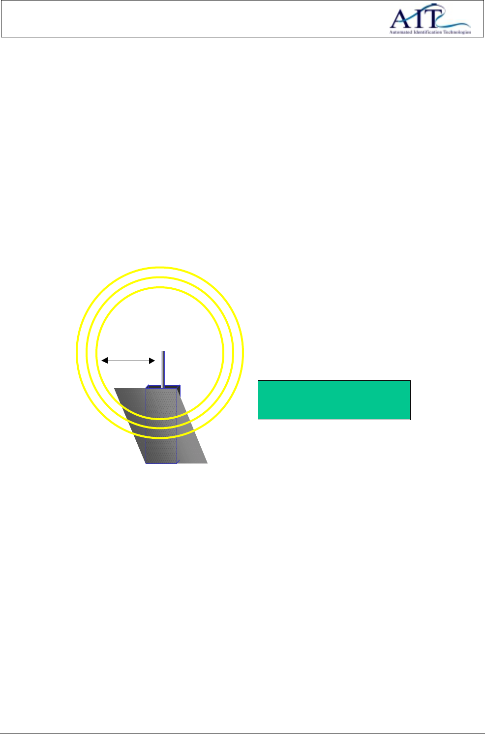
Parameters:
•Time-Interval between transmissions.
•Identification Number.
5 - 10 Meter
Figure 1: Tag Block Diagram
The tag perform the following functions:
• Transmit ID at pre-set time-intervals.
• Accepts new parameters when being reprogrammed with a tag programmer.
• Depending on the environment in which the tags are being used, and the type of tag, it can transmit up
to a range of 10 meters.
1.3 DOCUMENT OVERVIEW
This document is intended for use by users and system vendors of the Link-It Tagging System. Operational
details of the tag are described.
• Chapter 2 describes the performance parameters of the tag. Operational, functional and physical char-
acteristics of the tag are explained.
• Chapter 3 describes the interface details of the tag. Software interfaces are explained.

Link-It Active Tag 5 of 15
• Chapter 4 describes the principal of operation of the tag. Aspects such as communication between com-
ponents of the system as well as operational concepts are explained.
• Chapter 5 contains information regarding the installation procedures for the various tags. This information
will particularly useful for system integrators and solution providers.

Link-It Active Tag 6 of 15
2 PERFORMANCE PARAMETERS
2.1 OPERATIONAL DESCRIPTION
2.1.1 Tagging System
The main function of the system is to monitor and control equipment, assets and people in an area or building
in terms of position. This is done by active tags that each transmits a unique ID within a pre-set time interval.
Multifunction readers, appropriately situated in the area where position monitoring has to be conducted, inter-
pret signals transmitted by the tags. All tags interpreted by a specific reader are in fairly close proximity to the
reader; enabling the position of the tags to be established quite accurately.
The system can also monitor movement of equipment. This function is implemented by using tags designed to
sense movement.
2.1.2 Tags
2.1.2.1 Basic Tag
The basic tag can be configured to send its unique ID at a pre-set time-interval. This tag is usually used on
equipment where the position should be monitored. A Tag Programmer is used to externally configure the tag.
The tag is capable of transmitting its ID up to a distance of 5m. It must be however be emphasised that the
transmission range may vary from environment to environment.
2.1.2.2 Tag with movement sensor
The tag with movement sensor senses movement. It transmits its unique ID at pre-set intervals, but will go into
alarm mode automatically when it senses disturbance. This type of tag is generally used on assets that should
not be moved, or subjected to vibration, in normal circumstances. The tag is capable of transmitting its ID up
to a distance of 5m. It must be however be emphasised that the transmission range may vary from environ-
ment to environment.
2.1.2.3 Slimline Tag
The slimline tag can be configured to send its unique ID at a pre-set time-interval. This tag is usually used on
equipment and people where the position should be monitored. A Tag Programmer is used to externally con-
figure the tag. The tag is capable of transmitting its ID up to a distance of 10m. It must be however be em-
phasised that the transmission range may vary from environment to environment.
2.2 FUNCTIONAL CHARACTERISTICS
2.2.1 Tagging System
The system is capable of determining the relative position of tags. Tags can be attached to assets or people.
Link-It Active Tag 7 of 15
2.2.2 Tags
2.2.2.1 Normal Tag
The normal tag can be attached to assets, equipment, and people. The tag is used to perform the following
functions in the system.
• Transmit its unique pre-programmed ID at a pre-programmed time interval.
2.2.2.2 Tag with movement sensor
The tag with movement sensor can be attached to assets, equipment, and people. It is used to perform the
following functions in the system.
• Transmit its unique pre-programmed ID at a certain pre-programmed time interval.
• Transmit its unique pre-programmed ID each time that the tag senses movement.
2.2.2.3 Slimline Tag
The slimline tag can be attached to assets, equipment, and people. The tag is used to perform the following
functions in the system.
• Transmit its unique pre-programmed ID at a pre-programmed time interval.
2.3 PHYSICAL CHARACTERISTICS
2.3.1 Normal Tag and Tag with movement sensor
Both these tags have the same physical characteristics. The physical characteristics of tags are described in
the table below.
Figure 2: Active Tag
Parameter Specification
Size 61mm x 30mm x 9mm
Weight < 25gms
Type of material PVC (ultrasonically sealed) IP 65 rating
Table 4: Physical Characteristics of Normal and Movement Tags
Link-It Active Tag 8 of 15
Tag colours are described below:
• Normal tags are Light Grey
• Tags with movement sensors are Dark Grey.
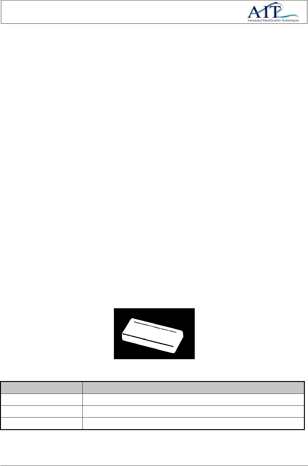
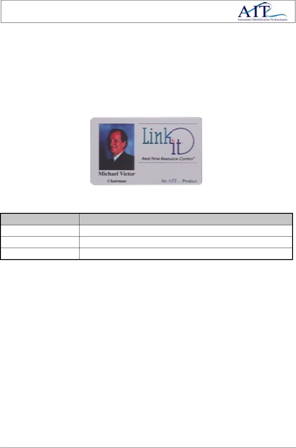
2.3.2 Slimline Tag
Slimline tags are flat and are normally used in personnel tagging and laptop tagging applications. The physical
characteristics of slimline tag are described in the table below.
Figure 3: Active Tag
Parameter Specification
Size 86mm x 54mm x 5mm
Weight < 30gms
Type of material PVC (ultrasonically sealed) IP 65 rating
Table 5: Physical Characteristics of Slimline Tags
Tag colours are described below:
• Enclosures are manufactured in light and dark grey.
• Custom labels can be printed onto the slimline tag.

Link-It Active Tag 9 of 15
3 INTERFACE DESCRIPTION
3.1 BASIC TAG OR TAG WITH MOVEMENT SENSOR
Tags basically have two data interfaces that are explained in the paragraphs below.
3.1.1 RF Interface
Tags are designed to operate in the more commonly known free-bands (403MHz, 868MHz). The typical
power output is less than 100uW.
3.1.2 Programming Interface
Each Tag has to be programmed with specific variables. These variables include time-interval of its transmis-
sions and the tags unique ID. A Tag Programmer is used for this purpose.
Link-It Active Tag 10 of 15
4 TECHNICAL DESCRIPTION
4.1 PRINCIPAL OF OPERATION
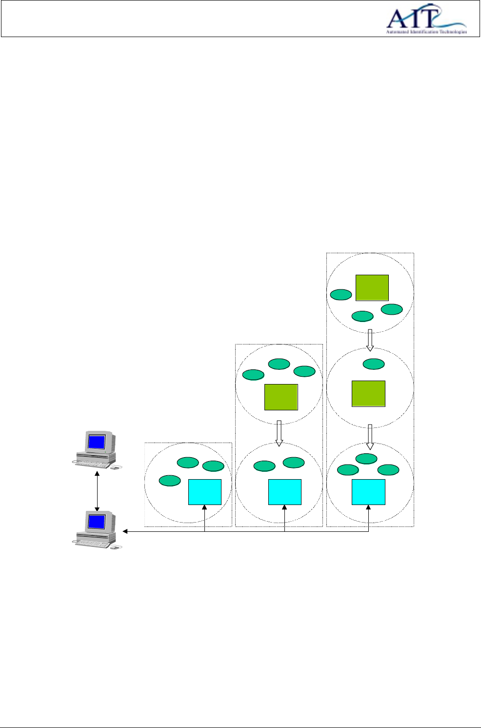
The principal of operation of the Link-It Tagging System s described in this section. A basic knowledge of the
system is essential before commencing with any installations or implementation. A basic system block dia-
gram is illustrated in Figure 4. Tags A ! N attached to assets, equipment and people are recognised and in-
terpreted by a network of Readers and Repeaters. In larger areas Repeaters are used in conjunction with
Readers to increase the area of operation. In smaller areas one reader will normally be sufficient to read all
tags in that area. Information regarding the relative tag positions is sent via cables from readers to a PC.
Large Area
Reader 1
Repeater 1
Reader 2 Reader 3
Repeater 2
Repeater 3
TagD TagE
TagC
TagB
TagA
TagM
TagN
TagLTagJ TagK
TagI
TagF
TagG
TagH
Small Area
Medium Size Area
Server
PC
TagO
Figure 4: Basic System Block Diagram
4.1.1 TAG TO READER/REPEATER COMMUNICATION
Tag to Reader/Repeater communication is done via a RF channel. The interface is described in paragraph
3.1.1. Tags transmit their pre-programmed ID’s at a certain time-interval. These ID’s are received and inter-
preted by the Reader/Repeater. Readers/repeaters can be configured filter data received from tags. This
means that only certain tags may be interpreted by the reader/repeater.
Figure 5 illustrates a configuration of two repeaters (Repeater1 and Repeater2), one reader (Reader1) and
12 tags (TagA ! TagL). Repeater2 can be configured to receive data only from tags except for TagE, TagF,
TagG and TagH. All other tags that fall within Repeater2 receive zone will be discarded. However, this type of
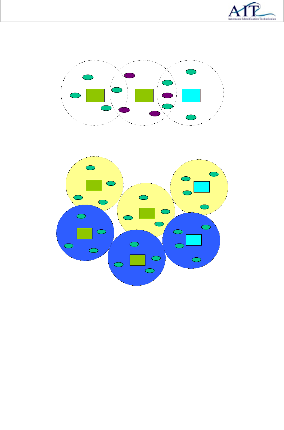
Link-It Active Tag 11 of 15
configuration is not recommended, but would rather be used in applications where two different systems are
situated in close proximity of each other as illustrated in Figure 6.
TagA
Reader1Repeater2Repeater1
TagC
TagB
TagD
TagH
TagE
TagG
TagF
TagK
TagI
TagL
TagJ
Figure 5: Tag to Reader/Repeater Communication
TagA
Reader1
Repeater2
Repeater1 TagC
TagB
TagD
TagH
TagE
TagG
TagF
TagK
TagI
TagL
TagJ
System 1
TagA
Repeater1 TagC
TagB
TagD
Repeater2
TagH
TagE
TagG
TagF
Reader1
TagK
TagI
TagL
TagJ
System 2
Figure 6: Tag to Reader/Repeater Communication of 2 Different Systems
Link-It Active Tag 12 of 15
5 CONFIGURING TAGS IN THE LINK-IT SYSTEM
5.1 PROGRAMMING OF THE TAGS
Custom Tag Programming software is supplied to each user and vendor of the Link-It Tagging System.
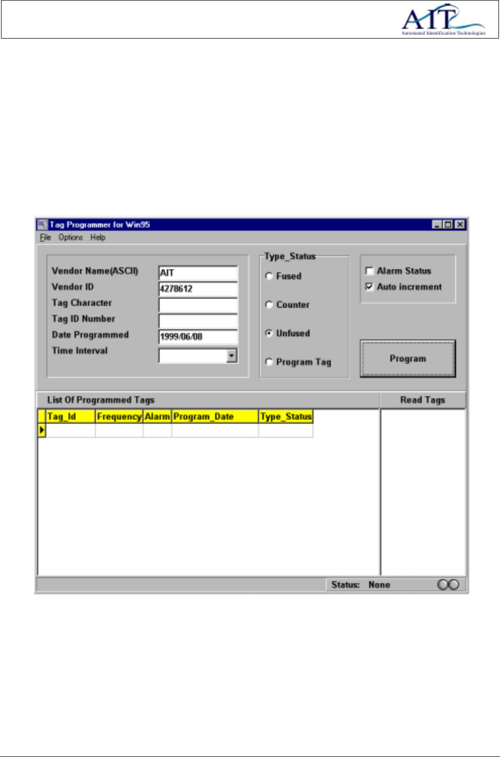
The Tag Programming Software runs on any IBM compatible PC using a Windows 95 operating system. The
program is installed by running “setup.exe” on Disk 1 of the installation disks. A snapshot of the programming
software is illustrated in Figure 7.
Figure 7: Tag Programming Software
Please insure that a Tag Programmer is connected to communications port 2 of the PC before attempting to
program tags.
The program functions are explained in the paragraph below:
• Vendor Name (ASCII) : 3 Byte Vendor ID displayed in ASCII format. Note that the ID must al-
ways be 3 bytes in length. The Vendor Name will be pre-programmed by

Link-It Active Tag 13 of 15
AIT, and will not be configurable for the user.
• Vendor ID : 3 Byte Vendor ID displayed in decimal format. The Vendor ID is pro-
grammed into the Tag. This is a fixed value pre-programmed by AIT
• Tag Character : Tag ID displayed in ASCII format. Note that the Tag ID must always be 4
bytes in length.
• Tag ID : Tag ID displayed in decimal format. This is the ID that is programmed into
the Tag. This is a user configurable option. The range of values available
is 0000000000 ! 4294967295 and must always be 10 digits in length.
• Date Programmed : Current Date. The date is not programmed into the tag but is inserted into
the database for further reference in configuration management.
• Programming Sequence :
• Coloured Indicator : Indicator to indicate current status and step in programming sequence.
• Text Box : Indicates all tag IDs interpreted by the programmer after the last pro-
gramming sequence
• Type Status Frame :
• Fused : If the tag is programmed with this option, no future programming of the
tag will be allowed
• Counter : Reset the Counter Byte to 0
• Unfused : Default option. Tag can be re-programmed in future
• Program Tag : Program the tag as a Program Tag
• Auto-increment Frame :
• Checked : Sets the Tag Programming Software to auto-increment the ID to be pro-
grammed to the next tag.
• Not Checked : Opposite of above
• Alarm Status Frame :
• Checked : Sets the Alarm option of the tag.
• Not Checked : Do not set the alarm status of the tag
• Time Interval : Time Interval between Tag transmissions
• 3 : 3 Second time interval between transmissions.
• 2 : 2 Second time interval between transmissions.
• 1 : 1 Second time interval between transmissions.
• 0.5 : 0.5 Second time interval between transmissions.
• 0.3 : 0.33 Second time interval between transmissions.
• 0.16 : 0.16 Second time interval between transmissions.
• List of programmed
tags : Displays a list of all tags that has been programmed. The user uses the
table for verification purposes.
• Tag ID Column : ID of the tag
• Frequency Column : Time Interval of the Tag

Link-It Active Tag 14 of 15
• Alarm Column : Display alarm status of the tag
• Program Date Column : Display the date on which the tag has been programmed.
• Type Status Column : Displays the tag type.
• Read Tags : Displays a list of all the tags currently being read by the programmer.
The following paragraph describes the typical programming sequence for a tag.
• Install the Programming software by running “setup.exe” on disk 1.
• Connect the Programmer to communications port 2 of the PC.
• Run the Programming Software.
• Enter the 10 digit unique ID for the tag in the “Tag ID Number” box.
• Select all other options.
• Ensure that the tag is correctly placed on the programmer.
• Press the Program button.
• Follow Instructions on the screen.
• Repeat for next tag. (No need to enter next ID if the “Auto Increment” option is checked)
5.2 INSTALLATION OF THE TAGS
5.2.1 Normal Tags
This type of tag is used in a variety of tagging applications. Depending on the application, tags are attached to
equipment with glue, epoxy, velcro or double sided tape.
5.2.2 Tag with movement sensor
The movement tag is used in applications where slight movement of equipment needs to be monitored. . De-
pending on the application, tags are attached to equipment with glue, epoxy, velcro or double sided tape.
5.2.3 Slimline Tag
The slimline tag is normally used in personnel tagging application as well as laptop tagging applications. A
slimline tag bracket can be used to attach the slimline tag to personnel, the tag can however be kept in a per-
sons pocket or carried by hand. The slimline tag is attached to laptops by means of double-sided tape, velcro,
or glue.
Link-It Active Tag 15 of 15
6 NOTES
6.1 APPROVALS
This device complies with Part 15 of the FCC Rules. Operation is subject to the following
two conditions: (1) this device may not cause harmful interference,and (2) this device
must accept any interference received, including interference that may cause undesired
operation.
6.2 ABBREVIATIONS
Abbreviation Meaning
CR Carriage Return
EOM End of Message
I/O Input/Input
ID Identity
LF Line Feed
LSB Least Significant Bit
UPS Uninterruptible Power Supply
M Meter
Mm Millimeter
MSB Most Significant Bit
NC No Connection
PC Personal Computer
Pwr Power
RF Radio Frequency
Rx Receive
SOM Start of Message
Tx Transmit
RFID Radio Frequency Identification
Table 6: Abbreviation