Wayne Fueling Systems VISTA RF ID Tag Reader User Manual 06206 10 FCC Vista
Wayne Fueling Systems LLC RF ID Tag Reader 06206 10 FCC Vista
UserManual.wiki
>
Wayne Fueling Systems
>
VISTA User Manual
>
user manual 1 of 2
Contents
1.
user manual 1 of 2
2.
user manual 2 of 2
3.
user manual statement
user manual 1 of 2
Navigation menu
Upload a User Manual
Namespaces
Wiki Guide
HTML
PDF
Info
Views
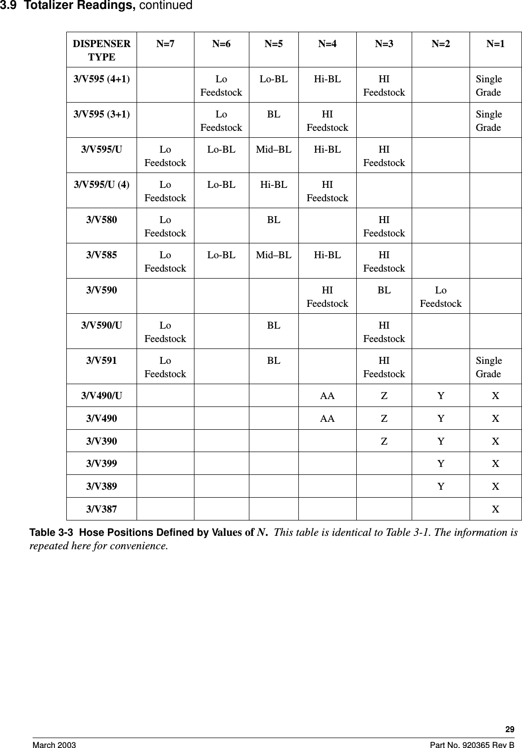
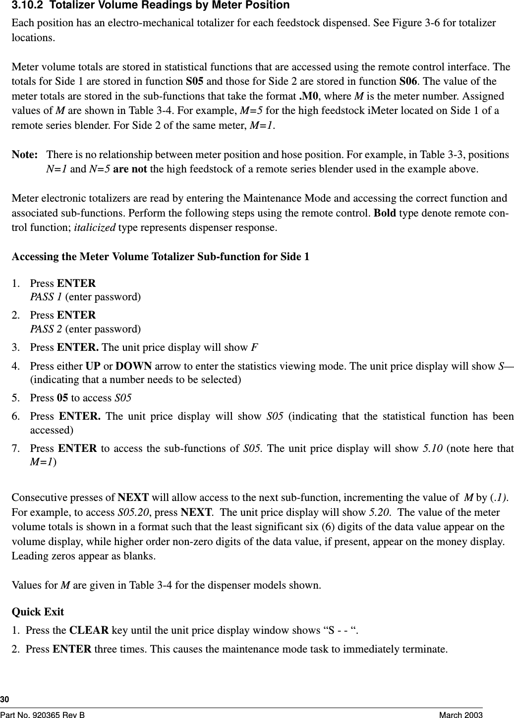
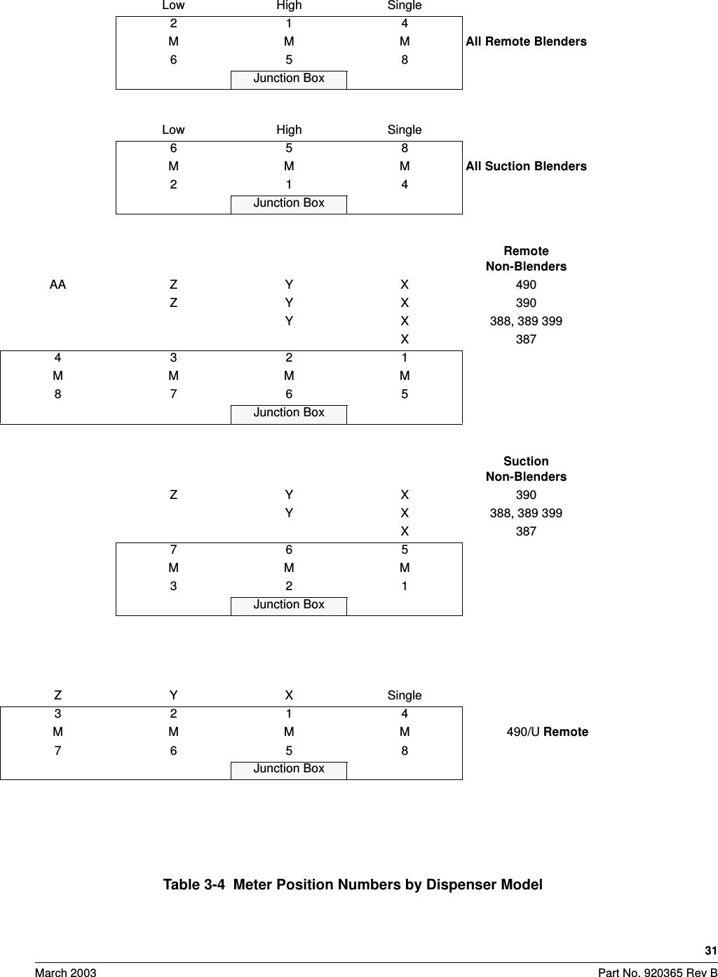
User Manual
Discussion / Help
Navigation