Wellington Drive Technologies CLICK1 Bluetooth LE transmission adaptor, SCS Click User Manual Part 2 of 2
Wellington Drive Technologies Ltd Bluetooth LE transmission adaptor, SCS Click Users Manual Part 2 of 2
Contents
- 1. Users Manual_Part 1 of 2
- 2. Users Manual_Part 2 of 2
Users Manual_Part 2 of 2
MOBILE GUI - cont
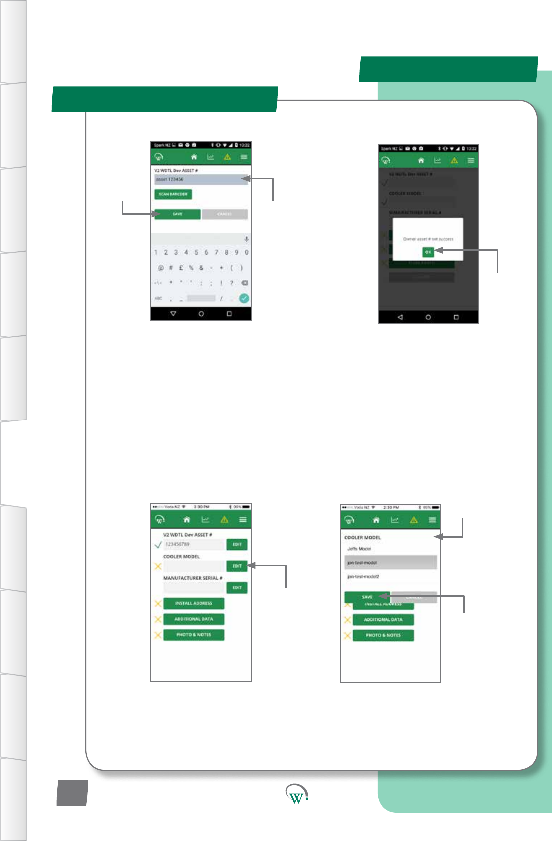
In-Field Setup
Enter Asset number manually.
Or
Barcode scan Asset number
usingthephone’scamera.
A list of available cooler
models will drop down.
Choose
SAVE to save
changes.
Choose OK
to accept.
Enter Asset
number.
Choose SAVE to
savechanges.
Choose EDIT
to edit Cooler
model.
Choose the cooler
model from the list
of available models.
TABLE OF
CONTENTS
INTRODUCTION
& WARNINGS
DESCRIPTION
& INSTALLATION
PROCESS
OVERVIEW
AUTHENTICATION IN-FIELD SET-UP UPGRADING
FIRMWARE
TECHNICAL
SPECIFICATION
GLOSSARY APPENDICES
PD0012 V1.0 – 10 Oct 2017
16
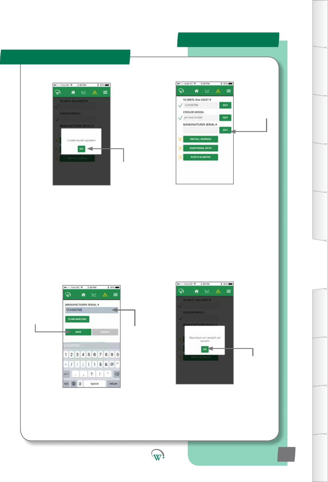
MOBILE GUI - cont
In-Field Setup
Choose EDIT to
add the cooler’s
Manufacturer
Serial Number.
Enter Serial number manually. Or
BarcodescanAssetnumberusingthe
phone’s camera.
Enter Serial
number.
Choose
SAVE to save
changes.
Choose OK
to accept.
Choose OK
to accept.
TABLE OF
CONTENTS
INTRODUCTION
& WARNINGS
DESCRIPTION
& INSTALLATION
PROCESS
OVERVIEW
AUTHENTICATION
IN-FIELD SET-UP
UPGRADING
FIRMWARE
TECHNICAL
SPECIFICATION
GLOSSARY
APPENDICES
PD0012 V1.0 – 10 Oct 2017 17
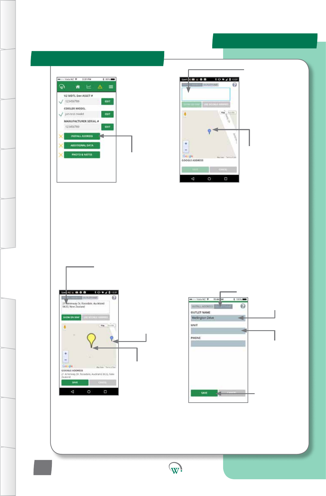
MOBILE GUI - cont
In-Field Setup
It is not necessary to
select SAVE at this
point.
IfyouchoseSAVEaercompleng
the previous step, select INSTALL
ADDRESStogetbacktothis
screen.
If GPS is turned
o,typetheoutlet
address in the
INSTALL ADDRESS
box and select SHOW
ON MAP.
Manually enter
the address if the
Googleaddressisnot
correct.
If GPS is turned
on, the phone will
automacallylocate
yourcurrentposion
(bluemarker).
Select INSTALL
ADDRESS
Enter outlet name
and other details.
TheUNITeldisfor
locaoninformaon
which is useful, but
not part of the street
address,e.g.“2nd
oor”or“unit3”.
Choose SAVE to
savechanges.
Double tap the map
screentoposionthe
cooler’sexactlocaon
with a yellow marker.
Dragtheyellow
marker around to
posionthecooler’s
exactlocaon.
SelectOUTLET/
UNIT tab.
TABLE OF
CONTENTS
INTRODUCTION
& WARNINGS
DESCRIPTION
& INSTALLATION
PROCESS
OVERVIEW
AUTHENTICATION IN-FIELD SET-UP UPGRADING
FIRMWARE
TECHNICAL
SPECIFICATION
GLOSSARY APPENDICES
PD0012 V1.0 – 10 Oct 2017
18
Note:
Itisstronglypreferabletodothisprocesswhileonline,asotherwisethereisahighchanceof
enteringanun-interpretableaddressandnotrealisingit.Ifyouarenotonlinewhiledoingthis
process,GoogleMapslookupwon’twork.Inthiscase,justtypeintheaddress.
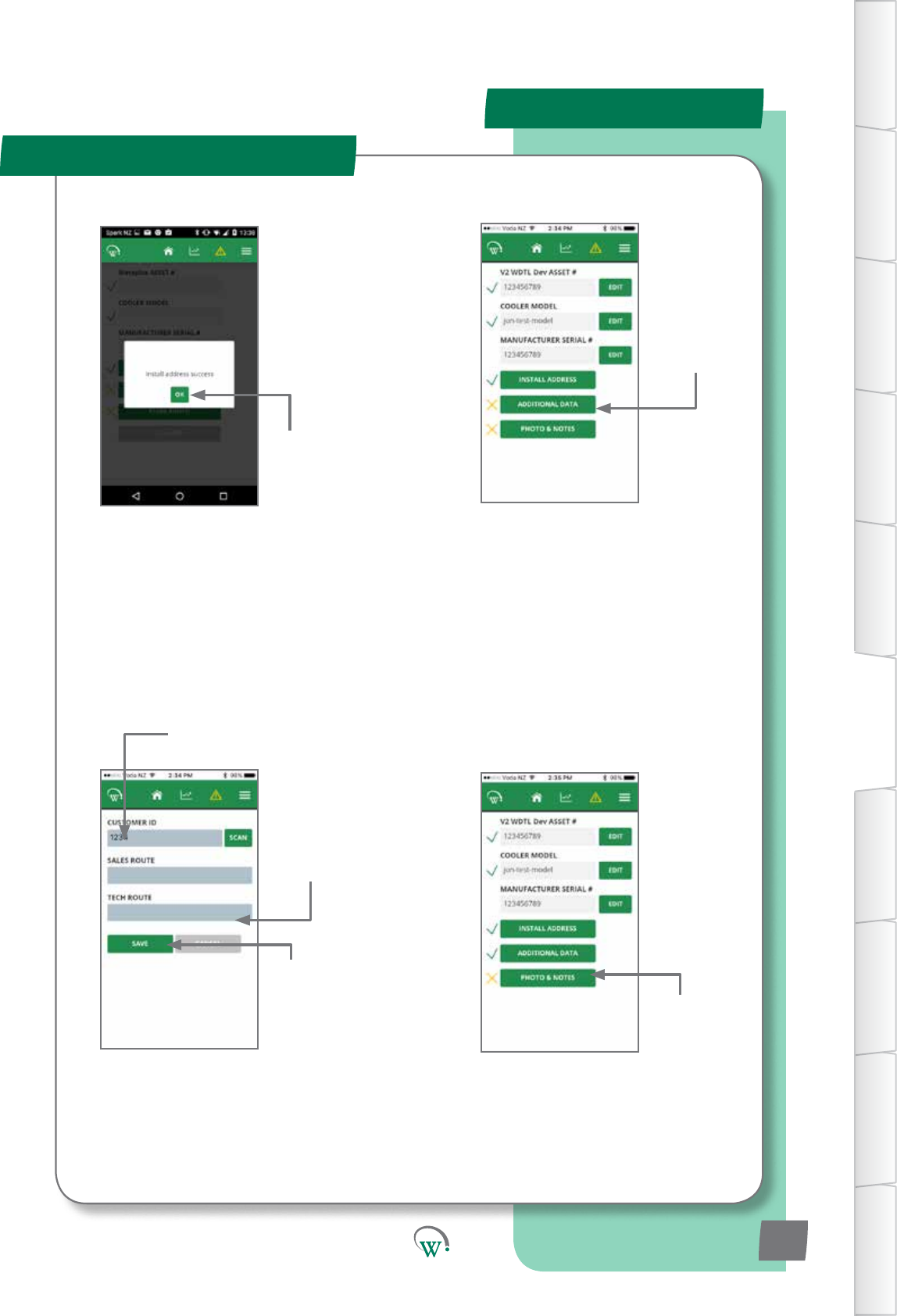
MOBILE GUI - cont
In-Field Setup
Enter Customer ID.
Select
ADDITIONAL
DATA
Enter CUSTOMER ID manually.
Or
Barcode scan Asset number
usingthephone’scamera.
Choose
SAVE to save
changes.
It is not necessary to
enteranythinginthe
SALES ROUTE and
TECHROUTEelds.
Choose OK
to accept.
Select PHOTO
&NOTES.
TABLE OF
CONTENTS
INTRODUCTION
& WARNINGS
DESCRIPTION
& INSTALLATION
PROCESS
OVERVIEW
AUTHENTICATION
IN-FIELD SET-UP
UPGRADING
FIRMWARE
TECHNICAL
SPECIFICATION
GLOSSARY
APPENDICES
PD0012 V1.0 – 10 Oct 2017 19
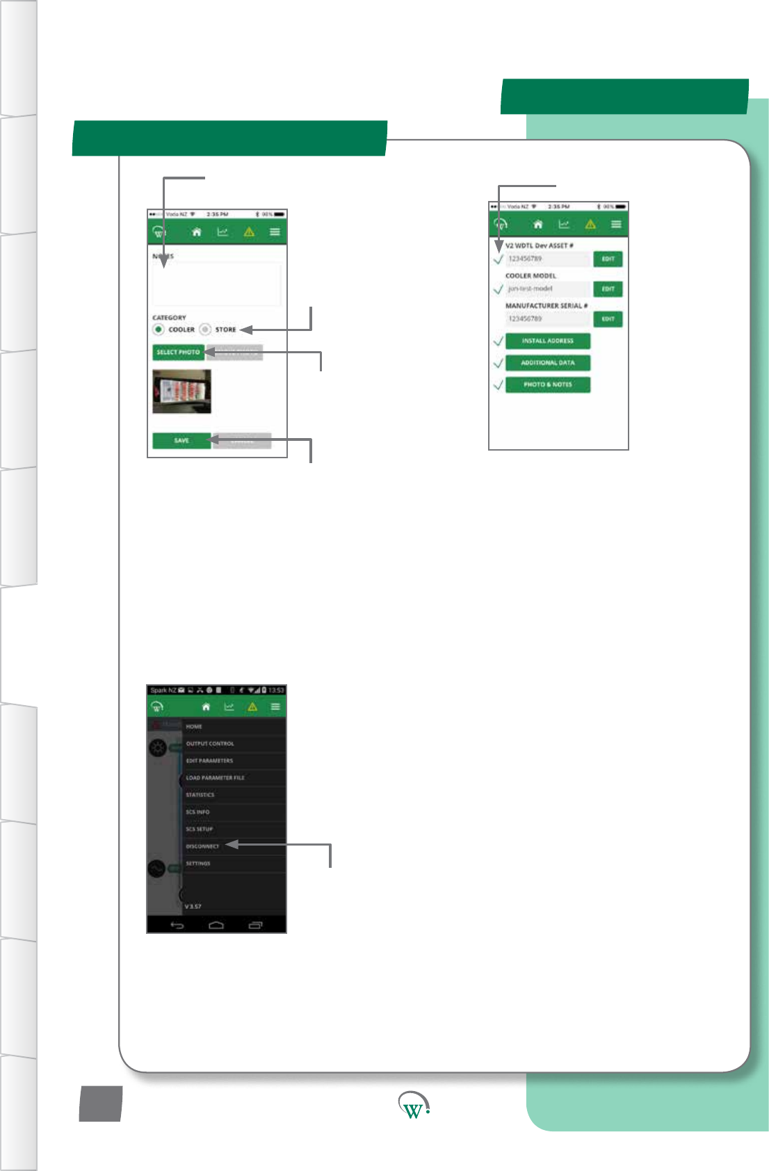
MOBILE GUI - cont
In-Field Setup
It is important to complete the disconnect
step to ensure that all asset data is
properly stored in the SCS Click.
Agreenckbesideeacheld
indicatesalltheeldsareset
andinstallaoniscomplete.
The manufacturer’s serial
numberdoesn’tgetagreenck
becausethesystemregardsthis
asoponalinformaon.
Select COOLER to
upload a cooler
photo, or STORE
to upload a store
photo.
Enter any other
informaonrelevantto
this photo.
Choose SELECT
PHOTO to upload
the photo from
yourphonegallery.
Choose SAVE to
savechanges.
Choose Disconnect
from the menu
to complete the
process.
TABLE OF
CONTENTS
INTRODUCTION
& WARNINGS
DESCRIPTION
& INSTALLATION
PROCESS
OVERVIEW
AUTHENTICATION IN-FIELD SET-UP UPGRADING
FIRMWARE
TECHNICAL
SPECIFICATION
GLOSSARY APPENDICES
PD0012 V1.0 – 10 Oct 2017
20
Note:
You can add notes without a photo, or a photo without notes. You can only add one photo at a
me.Toaddextraphotos,selectPHOTO&NOTESagainandrepeatthestepsabove.
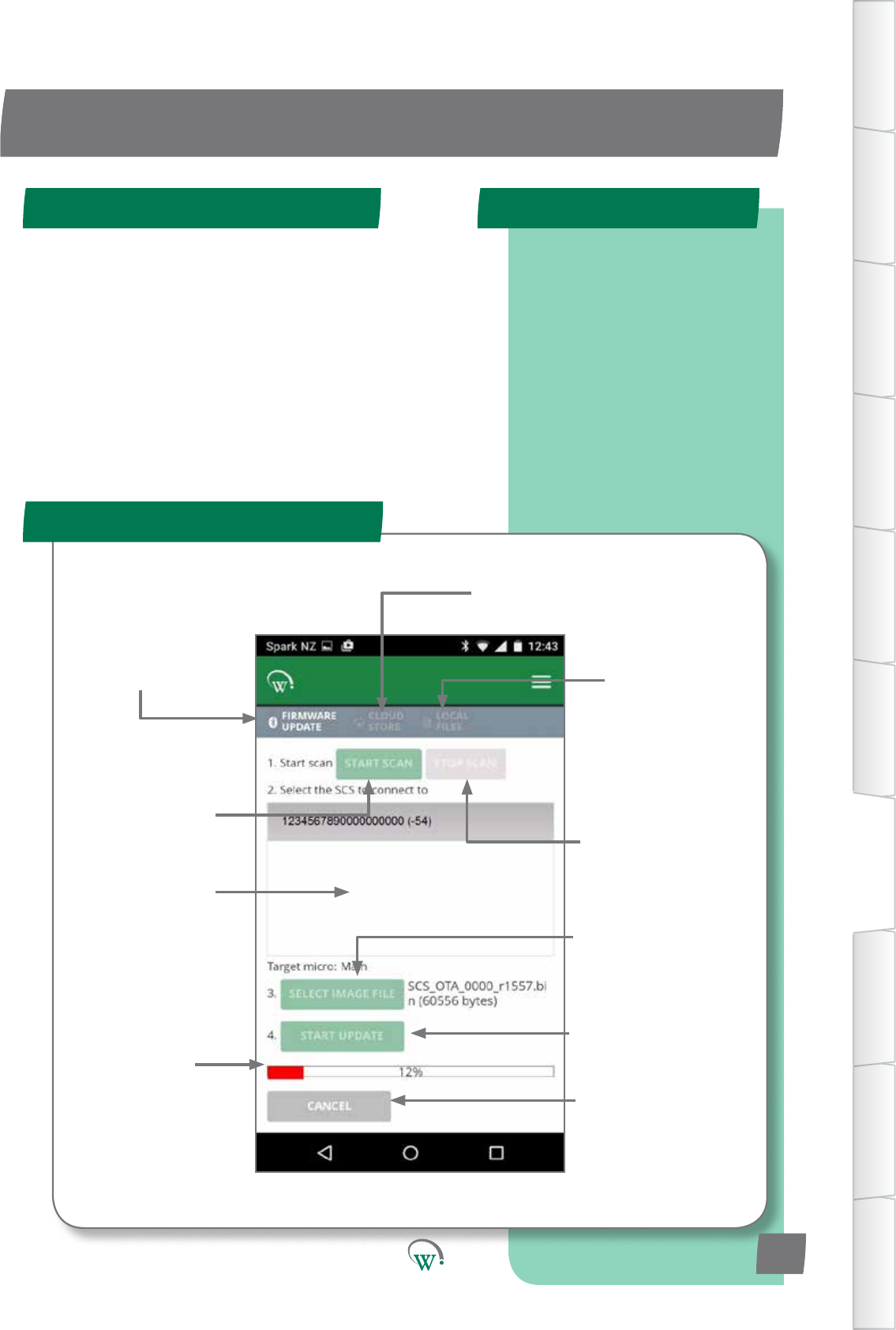
UPGRADING FIRMWARE
Quick Read
FIRMWARE UPDATE Screen
SCS Click Programming Steps
Navigatesto
this Screen
Screenforselecon
of Cloud stored
Firmware Files
Screen for
management
of locally stored
Firmware Files
IniatestheSCS
Clickscanning
process
Stops the SCS Click
scanningprocess
Windowshowing
visible SCS Click Forseleconof
rmwareletobere-
ashedontoSCSClick
Toiniatethe
reashingprocess
Reashing
Status bar
To terminate
thereashing
process
Need New Screen shot
TABLE OF
CONTENTS
INTRODUCTION
& WARNINGS
DESCRIPTION
& INSTALLATION
PROCESS
OVERVIEW
AUTHENTICATION
IN-FIELD SET-UP
UPGRADING
FIRMWARE
TECHNICAL
SPECIFICATION
GLOSSARY
APPENDICES
Step 1: Select controller.
Step 2: Select Bin File.
Step 3: Connect.
Step 4: Verify and
Program.
PD0012 V1.0 – 10 Oct 2017 21
Firmware can be updated from either the mobile or desktop
app. The steps are the same for both. Screenshots used are
from the mobile app, but look the same on the desktop app
The SCS click contains a microprocessors.
•Mainmicroresponsibleforallcontrolalgorithms.
UPDATE PROCESS
Step 1 Step 2
Step 4
Step 3
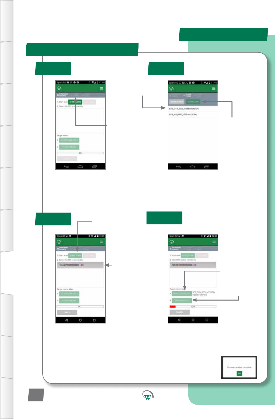
MOBILE GUI - cont
Step 3a:
Startscanning
for SCS Click to
upgrade
Step 3b:
Select SCS Click to
Upgrade
(Bluetooth Indicator will
ashonselectedSCS
Click once successfully
connected)
Step 4c:
Ensure“FirmwareUpdateComplete”is
displayedaerprogramming.Otherwise,
youwillneedtotryagain.
Step 4a:
Select Locally
Stored Firmware
leforUpgrade
Step 4b:
Starttheupgrade
Step 2a:
Selectthele
you want to use
Note:
SCSCLICK_OTAareMainmicroles.
Step 1:
Select Cloud
Stored Firmware
Files
Step 2b:
Choose
DOWNLOAD
TABLE OF
CONTENTS
INTRODUCTION
& WARNINGS
DESCRIPTION
& INSTALLATION
PROCESS
OVERVIEW
AUTHENTICATION IN-FIELD SET-UP UPGRADING
FIRMWARE
TECHNICAL
SPECIFICATION
GLOSSARY APPENDICES
PD0012 V1.0 – 10 Oct 2017
22
Need New Screen shots

POWER
Supply Voltage 5Vdc (supplied by EMS)
Power Consumption 150mW maximum
UART 5Vdc Full duplex
ENVIRONMENTAL
Operational Temperature Range -10°C to +55°C (-14°F to +131°F)
<90% RH non-condensing
Storage Temperature Range -40°C to +80°C (-40°F to +176°F)
<90% RH non-condensing
CONNECTIVITY
Bluetooth™ Capability Bluetooth™ SMART
Supported Windows O/S
for GUI module
Windows 7
Windows 8
Windows 8.1
Window 10
Supported Mobile App Devices
Android with BT 4.0 and OS 4.4.3 or above
iPhone 4S or later
iPAD 3rd Gen or later
iPAD mini
PHYSICAL
Dimensions SCS Click Overall Dimensions:
10.8mm (H) x 11.7mm (W) x 17.6mm (D)
Weight 2g (0.07oZ)
Activity Indicators LED Indicator
Housing Materials Main Housing: PC
TECHNICAL SPECIFICATIONS
Technical Specicaon Table
TABLE OF
CONTENTS
INTRODUCTION
& WARNINGS
DESCRIPTION
& INSTALLATION
PROCESS
OVERVIEW
AUTHENTICATION
IN-FIELD SET-UP
UPGRADING
FIRMWARE
TECHNICAL
SPECIFICATION
GLOSSARY
APPENDICES
PD0012 V1.0 – 10 Oct 2017 23

COMPLIANCE AND APPROVALS
Fire Rating UL94-V0
Electrical Insulation Rating Class II (when correctly installed)
Safety Compliance cUL*
Ingress Protection IP 40 (weather protection provided by EMS)
EMC
Immunity: EN6100-6-2, EN 301 489-1,
EN301 489-17
Emmissions: EN55014-1 , EN301 489-17 ,
EN300 328 V1.8.1
EN50371
FCC Part 15B and 15C EN 300 328
ICES-001, RSS-247, RSS-102
AS/NZS 4268, AS/NZS CISPR 22
European Directive: Restriction of
Hazardous Substances EU Directive 2002/95/EC (RoHS)
European Directive: Waste
Electrical and Electronic
Equipment
EU Directive 2002/96/EC (WEEE)
Bluetooth SIG BQB QDL*
Technical Specicaon Table
TABLE OF
CONTENTS
INTRODUCTION
& WARNINGS
DESCRIPTION
& INSTALLATION
PROCESS
OVERVIEW
AUTHENTICATION IN-FIELD SET-UP UPGRADING
FIRMWARE
TECHNICAL
SPECIFICATION
GLOSSARY APPENDICES
PD0012 V1.0 – 10 Oct 2017
24

FCC Declaraon
SPECIFICATIONS
TABLE OF
CONTENTS
INTRODUCTION
& WARNINGS
DESCRIPTION
& INSTALLATION
PROCESS
OVERVIEW
AUTHENTICATION
IN-FIELD SET-UP
UPGRADING
FIRMWARE
TECHNICAL
SPECIFICATION
GLOSSARY
APPENDICES
PD0012 V1.0 – 10 Oct 2017 25
CLASS B DEVICE
This device complies with Part 15 of the FCC Rules. Operation is subject to the following
two conditions:
1. This device may not cause harmful interference, and
2. This device must accept any interference received, including interference that may
cause undesired operation.
FCC Caution:
Changes or modications not expressly approved by the part responsible for compliance
could void the user’s authority to operate the equipment.
FCC Statement:
This equipment has been tested and found to comply with the limits for a Class B digital
device, pursuant to part 15 of the FCC Rules. These limits are designed to provide
reasonable protection against harmful interference in a residential installation. This
equipment generates, uses and can radiate radio frequency energy and, if not installed
and used in accordance with the instructions, may cause harmful interference to radio
communications. However, there is no guarantee that interference will not occur in a
particular installation. If this equipment does cause harmful interference to radio or
television reception, which can be determined by turning the equipment off and on,
the user is encouraged to try to correct the interference by one or more of the following
measures:
• Reorient or relocate the receiving antenna
• Increase the separation between the equipment and receiver
• Connect the equipment into an outlet on a circuit different from that to which the
receiver is connected
• Consult the dealer or an experienced radio/TV technician for help
RSS-Gen & RSS-247 statement:
This device complies with Industry Canada licence-exempt RSS standard(s).
Operation is subject to the following two conditions:
1. This device may not cause interference, and
2. This device must accept any interference, including interference that may cause
undesired operation of the device.
Le présent appareil est conforme aux CNR d’Industrie Canada applicables aux appareils
radio exempts de licence. L’exploitation est autorisée aux deux conditions suivantes :
1. l’appareil ne doit pas produire de brouillage, et
2. l’utilisateur de l’appareil doit accepter tout brouillage radioélectrique subi, même si
le brouillage est susceptible d’en compromettre le fonctionnement.
RSS-102 Statement:
This equipment complies with Industry Canada radiation exposure limits set forth for an
uncontrolled environment.
Cet équipement est conforme à l’exposition aux rayonnements Industry Canada limites
établies pour un environnement non contrôlé.

AC AlternangCurrent.
Acvity Anacvityisdenedasahumaninteraconwiththecabinet,
suchasopeningthecabinetdoortoaccesstheproductinside.
AcvitySensorState Usinginputsensorstodetermineiftherehasbeenanyacvity
orinteraconwiththecoolerunit.
Ambient Temperature Theaverageairtemperatureoutsideofthecoolerunit.
CE Mark ConformitéEuropéenne.TheCEmarksigniesthattheproduct
conformstoallapplicableEuropeanDirecvesrequiredbythe
EuropeanEconomicArea(EEA).
Cooler Unit Theunitcontainingtherefrigeraonsystemandaninsulated
spaceforstoringanddisplayingproduct.
cUL Mark ThecULMarksigniesthattheproductconformstothe
relevant safety compliance required by the USA and Canada.
DC Direct Current.
Defrost Cycle Amodewheretherefrigeraonsystemswitchesothe
compressor to defrost the evaporator coil. This may be assisted
byheangandbytheevaporatorfanblowingairacrossthe
evaporator coil.
Diagnoscs Theprocessofanalyzingdatafromthecontrollertodetermine
thecurrentfunconoftheunit,parcularlyforinialsetupand
faultnding.
Duty Cycle TheraoofCompressoronmetoome.
EUDirecve2002/95/EC(RoHS) TheEUDirecvewhichgovernstheRestriconofHazardous
Substances(RoHS)ingoods.Thisdirecveiscloselylinkedwith
theWasteElectricalandElectronicEquipmentdirecve(WEEE).
GLOSSARY
DenionTerm Used
TABLE OF
CONTENTS
INTRODUCTION
& WARNINGS
DESCRIPTION
& INSTALLATION
PROCESS
OVERVIEW
AUTHENTICATION IN-FIELD SET-UP UPGRADING
FIRMWARE
TECHNICAL
SPECIFICATION
GLOSSARY APPENDICES
PD0012 V1.0 – 10 Oct 2017
26

EUDirecve2002/96/EC(WEEE) TheWasteElectricalandElectronicEquipmentdirecve(WEEE),
whichgovernsthecollecon,recyclinganddisposalofelectrical
andelectronicgoods.Thisdirecveiscloselylinkedwiththe
RestriconofHazardousSubstancesdirecve(RoHS).
Evaporator Fan The fan which is used to blow internal air over the evaporator
coil.Theevaporatorcoiltakesheatawayfromtheair,cooling
the air down.
Evaporator Temperature The temperature detected on the outside of the evaporator coil.
GUI Graphical User Interface.
HACCP HazardAnalysis&CricalControlPointsisaprevenve
approachtofoodsafetyandstorageofmedicines,where
refrigeraoncontrolisrecognizedasacricalcontrolpoint.
HCCompable Suitableforusewithammablerefrigerantsinrefrigerators
complyingwithIEC60335-2-89.
HighVoltage Anypartoftherefrigeraonsystemwhichoperatesonvoltages
thatarehazardous.
Internal Temperature The temperature detected inside the cooler unit where the
product is placed.
IRAM Mark TheIRAMMarksigniesthattheproductconformstothe
relevantproductstandardsrequiredbyArgenna.
LED LightEmingDiode.
N.C. NotConnected',inrelaontotheHardwareSetUp.
Normal Mode Thestandardautomacrunningmode.
NSF Mark TheNSFMarksigniesthattheproductconformstothe
relevantfoodsafetyregulaonsfromtheindependentNSF
organisaon.
DenionTerm Used
TABLE OF
CONTENTS
INTRODUCTION
& WARNINGS
DESCRIPTION
& INSTALLATION
PROCESS
OVERVIEW
AUTHENTICATION
IN-FIELD SET-UP
UPGRADING
FIRMWARE
TECHNICAL
SPECIFICATION
GLOSSARY
APPENDICES
PD0012 V1.0 – 10 Oct 2017 27

OEM OriginalEquipmentManufacturer.
OverVoltage Astatewherethesupplypowervoltageishigherthanthe
designlimitsoftheequipment.
Products Productsaretheitemsbeingstoredinsidetherefrigerated
cabinet, for example chilled drinks.
RefrigeraonSystem Thecomponentscomprisingthecompleterefrigeraoncircuit,
includingcontroller,evaporator,expansionvalve,condenser,
compressor and evaporator fan.
Sensor Sensorsaredeviceswhichgenerateasignalusedtocontrol
devicesasaresultofadetectedenvironmentalchange.
Probesareakindofsensor,andthetwotermsareoenused
interchangibly.
Standby Modes Asequenceofcontrolmodesusedtosaveenergyduring
periods of lower use.
States Thestateofadevice(eg;'on'or'oFF')isusedbytheSCS
Connectcontrolertomakelogicdecisionswhencontrollingthe
device.
Thermostat Aswitchorsignaldevice,acvatedbychangesintemperature.
TransionModes Aseriesof“inbetween”modesthatcanbeusedtoadjust
set-pointandlighnglevels,withoutfullychangingbetween
Normal and Standby mode.
UL Mark TheULMarksigniesthattheproductconformstothe
relevant safety compliance standard published by Underwriters
Laboratories Inc.
UnderVoltage Astatewherethesupplypowervoltageislowerthanthe
requirements of the equipment.
VDE Mark TheVDEMarksigniesthattheproductconformstothe
relevantelectricalequipmentsafetyregulaonsfromthe
independentVDEorganisaon.
DenionTerm Used
TABLE OF
CONTENTS
INTRODUCTION
& WARNINGS
DESCRIPTION
& INSTALLATION
PROCESS
OVERVIEW
AUTHENTICATION IN-FIELD SET-UP UPGRADING
FIRMWARE
TECHNICAL
SPECIFICATION
GLOSSARY APPENDICES
PD0012 V1.0 – 10 Oct 2017
28
SERVICE CENTER CONTACT ADDRESSES
South America
North America
Australasia
Asia
Europe
North America
Australasia
Asia
Europe
© 2017 Wellington Drive Technologies Limited
21 Arrenway Drive, Rosedale, Auckland 0632, New Zealand
PO Box 302-533, North Harbour, Auckland 0751, New Zealand
Tel.: + 64 9 477 4500, Fax: + 64 9 479 5540,
E-mail: info@wdtl.com Website: www.wdtl.com