Westel Wireless Systems C100063 UHF Base Station Transceiver User Manual CHAPTER 4 OPERATING INSTRUCTIONS
Westel Wireless Systems Pty Ltd UHF Base Station Transceiver CHAPTER 4 OPERATING INSTRUCTIONS
Contents
OPERATOR MANUAL

Installation and Operator Handbook Operating Instructions
AMX-MA-00654 Issue 0.02 (USA) 1
TABLE OF CONTENTS
Page
4 OPERATING INSTRUCTIONS
4.1 INTRODUCTION....................................................................................................................................2
4.2 SWITCHES..............................................................................................................................................2
4.3 APPLYING POWER ...............................................................................................................................2
4.3.1 Initial Power-On Checklist........................................................................................................3
4.3.2 Power-On Faultfinding..............................................................................................................3
4.3.3 Fuse Replacement .....................................................................................................................4
4.3.4 Checking System Power Supply Outputs..................................................................................4
4.3.5 Replacing System Power Supply ..............................................................................................4
4.4 OPERATIONAL FAULTFINDING........................................................................................................5
4.5 CONFIGURATION.................................................................................................................................7
4.5.1 Fixed Channel Operation ..........................................................................................................7
4.5.2 Scan Channel Operation............................................................................................................7
4.6 LOCAL OPERATION.............................................................................................................................7
4.6.1 Monitoring Audio......................................................................................................................7
4.6.2 Making Calls.............................................................................................................................8
4.6.3 Changing Audio Volume ..........................................................................................................8
4.6.4 Changing Selected Channel: .....................................................................................................8
4.6.5 Squelch Adjustment ..................................................................................................................8
4.7 REMOTE OPERATION..........................................................................................................................8
LIST OF TABLES
4-1 RESET SWITCHES.......................................................................................................................................2
4-2 POWER-ON INDICATORS..........................................................................................................................3
4-3 FAULTFINDING CHART FOR POWER ON PROBLEMS........................................................................3
4-4 FAULTFINDING CHART FOR OPERATIONAL PROBLEMS.................................................................5

Installation and Operator Handbook Operating Instructions
AMX-MA-00654 Issue 0.02 (USA) 2
4 OPERATING INSTRUCTIONS
4.1 INTRODUCTION
After installation (as described in Chapter 3), normal operation of the DRB-25 is achieved by applying power
to the DRB-25 and switching on the rear panel power switch and the Power Supply Modules.
The DRB-25 Modules will perform self-test diagnostics after power is applied. Visual indicators on the
module front panels will convey the status of the DRB-25 to the Operator. If any of these visual indicators
show an error or fault code, simple faultfinding procedures may identify the problem and suggest an
immediate solution.
If operational checks reveal a fault in DRB-25 equipment, it may be necessary to replace it. Removal of
equipment is the reverse of the installation procedure described in Chapter 3. Any faulty items should be
carefully packaged and sent to an authorized repair center.
If faults are not corrected by substituting equipment at an operational level, contact the supplier or its
representative.
Additional connectors on the front and back panels of selected equipment allow maintenance personnel to
access functions for system configuration, operational statistics and faultfinding.
4.2 SWITCHES
There are two types of switches on the front panels of the DRB-25: power and reset switches.
If an AC supply is used with the DRB-25, there is a master power supply switch on the rear of the unit which
should be turned on first. The power switches on the front panel of the Power Supply Modules are switched
on next.
Recessed reset switches on the Transceiver, Controller and Interface Modules (optional) allow the equipment
to be reset. Table 4-1 describes each reset switch and its function.
Table 4-1 Reset Switches
Equipment Reset function
Interface Module Resets all modules (accessed from rear )
Controller Module Resets all modules (accessed from front)
Transceiver Module Resets the Transceiver Module (accessed from front)
4.3 APPLYING POWER
Perform the following final checks before applying power:
1. Check that the ground wires are connected to the DRB-25 primary ground from an external ground point.
2. Check that all equipment and connections are secure.
3. Ensure the power cable to the DRB-25 is plugged in securely and switch power on.
Installation and Operator Handbook Operating Instructions
AMX-MA-00654 Issue 0.02 (USA) 3
4. Switch on each Power Supply Module
Note that DC direct configurations have no power supplies or switches.
4.3.1 Initial Power-On Checklist
Refer to Table 4-2 to verify that power indications are correct. Should displays or indicators suggest a fault
condition, refer to 4.3.2 before proceeding.
The DRB-25 performs a self test and warm-up routine at power-on. During this, the Controller display
flashes while the Transceiver display remains blank. When the warm-up is complete, the Controller READY
indicator illuminates and the display changes to an oscillating pattern. The Transceiver then tunes to its
default channel and displays the channel number, and the unit is ready to operate.
At normal temperatures the Controller takes approximately one minute to warm up, however at -30°C warm-
up will take up to 10 minutes.
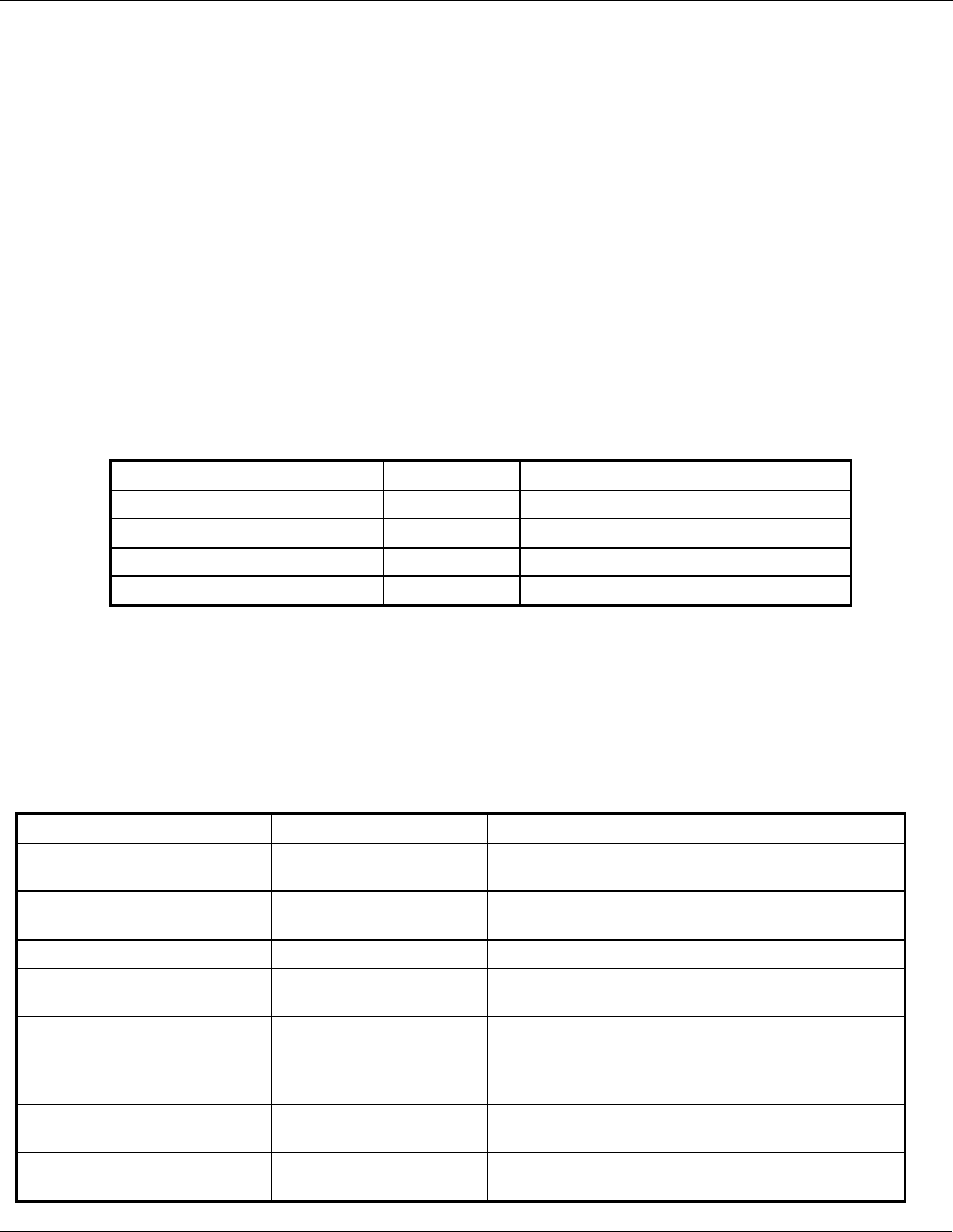
Table 4-2 Power-on Indicators
Equipment Indicator Normal Power On Indication
Power Supply Module ON Red lamp (in switch) lit
Controller Module 12 V PWR Green LED lit
Controller Module 7 V PWR Green LED lit
Transceiver Module PWR Green LED lit
4.3.2 Power-On Faultfinding
If the power-on indicators do not display normally, refer to Table 4-3 for simple faultfinding procedures.
Check each indication in sequence, proceeding to the next fault only when the previous one has been
eliminated.
Table 4-3 Faultfinding Chart for Power on Problems
Fault Probable Cause Recommended Action
Red Lamp in Power switch of
Power Supply Module not lit Poor supply connection Check all connections to the relevant equipment.
Supply faulty Check supply for correct output of 115 V, 240 VAC
or 12 / 24 VDC as appropriate.
Power fuse blown Replace fuse as detailed below.
OUTPUT lamp on Power
Supply Module not lit Power Supply Module
failure Substitute known good Power Supply Module and
re-test.
7 V PWR and/or 12 V PWR
lamps on Controller or
Transceiver Module fail to light
System Power Supply
Failure Check outputs of System Power Supply on
Backplane as detailed below. If either voltage is
absent, replace System Power Supply as detailed
below.
Controller Module Failure If Voltages are present, switch power off, substitute
known good Controller Module and re-test.
Transceiver Module
Failure If Voltages are present, switch power off, substitute
known good Transceiver Module and re-test.

Installation and Operator Handbook Operating Instructions
AMX-MA-00654 Issue 0.02 (USA) 4
Controller or Transceiver
module display error code in
the range E01 to E99
User serviceable failure
or module failure. See table B-1in Appendix B for likely cause and
recommended action
4.3.3 Fuse Replacement
AC DRB-25 units are protected by a single fuse located on the IEC connector/switch module. To check and if
required, replace the DRB-25 AC power fuse, proceed as follows:
1. Switch off all power to the DRB-25 and disconnect the Mains lead.
2. Unclip and withdraw the fuse slide immediately below the AC power connector on the IEC
connector/switch module on the rear of the cabinet.
3. Remove the fuse from the slide and check the continuity using a multimeter. If the fuse is ruptured,
replace with a new 205 size (20 x 5) 10 Amp cartridge fuse.
4. Fit the fuse to the slide and push the fuse slide firmly home.
DRB-25 units fitted with DC input are protected by fuses located adjacent to the DC power input connector.
Each Power Amplifier Module is protected by a separate fuse.To check and, if required, replace the DRB-25
DC power fuse, proceed as follows:
1. Switch off DC power to the DRB-25.
2. Unclip and withdraw the relevant fuse slide immediately below the DC power input connector on the rear
of the cabinet.
3. Remove the fuse from the slide and check the continuity using a multimeter. If the fuse is ruptured,
replace with a new ¼” x 1 ¼” 20 Amp cartridge fuse.
4. Fit the fuse to the slide and push the fuse slide firmly home.
4.3.4 Checking System Power Supply Outputs
To check the presence of 7 V and 12 VDC outputs from the System Power Supply, proceed as follows:
1. Disconnect and remove the Controller and Transceiver Modules from the front of the DRB-25 cabinet.
2. Observe the position of the backplane and identify the 12 VDC and 7 VDC test points between the
connectors for Transceiver 1 and the Controller
3. Connect the negative probe of a Multimeter to the 0 V test point or the DRB-25 system cabinet grounding
stud.
4. Using the positive lead, probe the +12 V and +7 V test points on the backplane card for the presence of the
indicated voltages ± 5%.
4.3.5 Replacing System Power Supply
If the above test indicates the lack of one or both voltage rails, replace the System Power Supply as follows:
WARNING

Installation and Operator Handbook Operating Instructions
AMX-MA-00654 Issue 0.02 (USA) 5
ENSURE ALL POWER IS SWITCHED OFF BEFORE
ATTEMPTING TO WORK ON THE DRB-25..
1. Switch off all power to the DRB-25 and disconnect the Mains lead.
2. Disconnect and remove the Interface Module from the rear of the DRB-25 cabinet.
3. Disconnect and remove the antenna system RF cables from the rear of the DRB-25.
4. Remove the four Philips head screws securing the left-hand rear panel of the DRB-25.
5. Ease the panel out from the Cabinet, disconnect the two RF cables from the inside of the bulkhead
connectors on the panel, and carefully lay the panel aside.
6. Remove the four Philips head screws from the right-hand rear panel of the DRB-25.
7. Ease the panel out from the DRB-25 Cabinet, disconnect the two RF cables from the inside of the
bulkhead connectors on the panel, and carefully lay the panel aside.
8. Locate the 4-pin DC power connector on the backplane and disconnect.
9. Locate System Power Supply DC input power leads, trace these leads to the DC power distribution
terminal block located in the area behind the right hand rear panel of the cabinet and disconnect. Note the
connection points for reference during refitting.
10. Using a 9/32 inch (7 mm) hexagonal nut driver, remove the four Nyloc nuts securing the Power Supply
Module to the studs on the rear of the left-hand panel and remove the Power Supply Module.
11. Refitting is a reversal of the removal procedure.
4.4 OPERATIONAL FAULTFINDING
If, during operation, the DRB-25 should fail to operate as expected, observe the status indicators and displays
of the modules as described in Chapter 2. Press the RESET button of the Controller Module and the
Transceiver Module and re-evaluate the condition. If this fails to clear the problem, proceed with the
faultfinding detailed in Table 4-4.
Table 4-4 Faultfinding Chart for Operational Problems
Indication Probable Cause Recommended Action
FAULT lamp on Controller
Module lit and error code
displayed
Controller Module
failure Note displayed error code on Controller Module:
see Appendix B for recommended action.
FAULT lamp on
Transceiver Module lit and
error code displayed
Transceiver Module
failure Note displayed error code on Transceiver Module:
see Appendix B for recommended action.
PA FAULT lamp on
Transceiver Module lit and
error code displayed
PA Module failure Note displayed error code on Transceiver Module:
see Appendix B for recommended action.
DRB-25 fails to transmit
SWR Error E08 Antenna System failure Check antenna system for damage and ensure
correct connections.
Power Amplifier Module
failure Switch power off, substitute known good Power
Amplifier Module and re-test.

Installation and Operator Handbook Operating Instructions
AMX-MA-00654 Issue 0.02 (USA) 6
Indication Probable Cause Recommended Action
DRB-25 fails to receive Antenna system failure Check antenna system for damage and ensure
correct connections.
Transceiver Module
failure Switch power off, substitute known good
Transceiver Module and re-test.
Failure of external
interfaces Interface Module failure Switch power off, substitute known good Interface
Module and re-test.

Installation and Operator Handbook Operating Instructions
AMX-MA-00654 Issue 0.02 (USA) 7
4.5 CONFIGURATION
If all the external indications are that the DRB-25 is operational, proceed with the configuration process using
the Transceiver Module Programmer application as described in Chapter 5. Once configuration has been
completed, the DRB-25 can be tested in its intended system environment.
Channels may be configured as fixed channels or scan channels as described in Chapter 5.
4.5.1 Fixed Channel Operation
Fixed channels will operate according to all the parameters entered in the channel settings dialog box (see
chapter 5).
4.5.2 Scan Channel Operation
Scan channels may be set up to scan between up to eight channels. The first channel selected in the scan
sequence will define the operating mode (local or remote basestation or repeater), station ID, timers,
encryption, power output and source priority during all scanning. The DRB-25 will scan between the channel
mode, spacing, talk group ID, receive configuration and transmit configuration of each selected channel.
The DRB-25 will scan sequentially through the selected channels, with a maximum scan rate of 2 channels
per second (500ms on each channel), unless a valid signal is detected on a channel. If a valid signal is detected
then the DRB-25 will remain on that channel until the call is completed, then continue scanning. The scan
channel can also be programmed with additional dwell times, such that the DRB-25 will remain on the
channel for the specified dwell time after the completion of a call, to allow for a return call.
4.6 LOCAL OPERATION
The DRB-25 may be operated locally by using a DTMF microphone and speaker connected to the front panel
handset socket of the transceiver module. Each transceiver must have a separate speaker and microphone.
4.6.1 Monitoring Audio
In single channel configurations a loudspeaker panel may be fitted to the unit to provide a speaker and volume
control (refer to 3.5.4.6). Audio may be also monitored from the Transceiver Module via an external speaker
connected to the front panel RJ45 audio connector.
The speaker will monitor audio on the selected channel of the transceiver, with receive parameters as defined
by the channel table entry in the Transceiver Module Programmer. In normal operation all traffic with a valid
NAC (digital mode) or CTCSS/CDCSS (analog mode) will be routed to the speaker. When operating as a
basestation the unit may be put into ‘monitor’ mode by keying the sequence *5* on a DTMF microphone
connected to the transceiver module audio connector. In monitor mode all traffic on the receive frequency
will be routed to the speaker irrespective of NAC or CTCSS/CDCSS. The DTMF key sequence *5* will
revert the basestation to normal squelch mode.
Note : the DTMF key # will erase any preceding (incomplete) DTMF key sequence.

Installation and Operator Handbook Operating Instructions
AMX-MA-00654 Issue 0.02 (USA) 8
4.6.2 Making Calls
Calls may be sent from the DRB-25 using a microphone connected to the transceiver module front panel RJ45
audio connector. Calls will be broadcast with the transmit NAC and Talkgroup ID (digital mode) or transmit
CTCSS/CDCSS (analog mode) of the transceiver’s current channel, as defined by the channel table entry in
the Transceiver Module Programmer.
4.6.3 Changing Audio Volume
If a loudspeaker panel is fitted, audio volume is controlled by the volume knob on the panel. If an external
speaker is connected, audio volume may be controlled using a DTMF microphone connected to the
transceiver module front panel RJ45 audio connector. The DTMF key sequence *2*nn* will set audio
volume to level ‘n’ between 00 (off) and 09 (full volume).
Note : the DTMF key # will erase any preceding (incomplete) DTMF key sequence.
4.6.4 Changing Selected Channel:
The transceiver’s current channel may be changed using a DTMF microphone connected to the transceiver
module front panel RJ45 audio connector. The DTMF key sequence *1*nnn* will change the transceiver to
channel ‘nnn’. The selected channel will be displayed on the front panel of the transceiver module.
Note : the DTMF key # will erase any preceding (incomplete) DTMF key sequence.
4.6.5 Squelch Adjustment
The receiver squelch level may be set in analog mode using a DTMF microphone connected to the transceiver
module front panel RJ45 audio connector. The DTMF key sequence *3*nn* will change the squelch level as
follows:
• *3*00* sets carrier squelch.
• *3*nn* sets squelch level to ‘nn’ dB SINAD where ‘nn’ is between 06 and 20.
• Squelch hysteresis is 2dB.
4.7 REMOTE OPERATION
The DRB-25 may be controlled remotely using any industry standard tone remote control console over two or
four wire telephone lines using leased lines or dial up, provided the DRB-25 is fitted with the corresponding
two or four wire line interface option. One line is used for each transceiver. To configure the DRB-25 for
remote operation:
1. Connect the two or four wire line(s) to the RJ45 line socket on the interface module at the rear of the
DRB-25.
2. Configure the allocation of function tones (F1 up to F12) if required (this functionality is part of the
Transceiver Module Programmer software described in chapter 5).
Connect the tone remote console to the line and operate according to the console manufacturer’s instructions.