Westel Wireless Systems C100063 UHF Base Station Transceiver User Manual 657 102
Westel Wireless Systems Pty Ltd UHF Base Station Transceiver 657 102
Contents
PROGRAMMING AND CONFIGURATION MANUAL

Installation and Operator Handbook Programming and Configuration
AMX-MA-00657 Issue: 1.02 (USA) Page 1
CONTENTS
Page
5 PROGRAMMING & CONFIGURATION ..................................................................................3
5.1 Overview......................................................................................................................................................................................3
5.2 Getting Started..........................................................................................................................................................................3
5.2.1 System Requirements ........................................................................................................................................................ 3
5.2.2 Making a Backup Copy of the DMR-25 Programmer Disk ....................................................................................... 3
5.2.3 Installing the DMR-25 Programmer Software .............................................................................................................. 3
5.2.4 Starting DMR-25 Programmer for the First Time........................................................................................................ 4
5.2.5 Connecting the Programmer to the Transceiver Module ............................................................................................ 4
5.2.6 Getting Help ........................................................................................................................................................................ 5
5.2.7 Running the DMR-25 Programmer................................................................................................................................. 5
5.2.8 Upgrading From TMP to DMR-25 ................................................................................................................................. 6
5.3 Configuring Communications ...............................................................................................................................................7
5.3.1 Serial Communications..................................................................................................................................................... 7
5.3.2 Modem Communications.................................................................................................................................................. 8
5.3.3 Exit Binary Mode............................................................................................................................................................... 8
5.4 Programming The Radio........................................................................................................................................................9
5.4.1 Radio Wide Settings.......................................................................................................................................................... 9
5.4.2 Channel Table ................................................................................................................................................................... 11
5.4.3 Tone Remote Settings ..................................................................................................................................................... 18
5.4.4 Encryption Settings.......................................................................................................................................................... 20
5.4.5 Squelch Groups ................................................................................................................................................................ 22
5.4.6 License Features............................................................................................................................................................... 24
5.4.7 Change Password ............................................................................................................................................................. 25

Installation and Operator Handbook Programming and Configuration
AMX-MA-00657 Issue: 1.02 (USA) Page 2
LIST OF FIGURES
Page
Figure 5-1 DMR-25 Programmer Main Window..........................................................................................................................4
Figure 5-2 Serial Comms Dialog Box................................................................................................................................................7
Figure 5-3 Modem Commands Dialog Box .....................................................................................................................................8
Figure 5-4 Radio Wide Settings Dialog Box....................................................................................................................................9
Figure 5-5 Channel Table Dialog Box.............................................................................................................................................11
Figure 5-6 Channel Settings Dialog Box........................................................................................................................................12
Figure 5-7 Configure Scan Channel Reference Dialog Box......................................................................................................16
Figure 5-8 Tone Remote Dialog Box...............................................................................................................................................18
Figure 5-9 Tone Remote Properties ................................................................................................................................................19
Figure 5-10 Encryption Settings Dialog Box.................................................................................................................................20
Figure 5-11 Add Key Dialog Box.....................................................................................................................................................21
Figure 5-12 Active Squelch Groups Dialog Box...........................................................................................................................22
Figure 5-13 Squelch Groups Dialog Box........................................................................................................................................23
Figure 5-14 License Features Dialog Boxes...................................................................................................................................24
Figure 5-15 Add License Dialog Boxes...........................................................................................................................................24
Figure 5-16 Change Password Dialog Box....................................................................................................................................25
LIST OF TABLES
Page
Table 5-1 System Requirements.........................................................................................................................................................3
Table 5-2 VHF Receive/Transmit Spacing ....................................................................................................................................14
Table 5-3 UHF-Lo Receive/Transmit Spacing .............................................................................................................................14
Table 5-4 Channel Parameters and Limits ...................................................................................................................................17
Table 5-5 Function Tone Frequencies ............................................................................................................................................19

Installation and Operator Handbook Programming and Configuration
AMX-MA-00657 Issue: 1.02 (USA) Page 3
5 PROGRAMMING & CONFIGURATION
5.1 Overview
Configuration of the Digital Mobile Radio is performed using the Windows-based DMR-25 Program
software application running on an IBM compatible PC connected via an RS-232 port (RJ-11) to the
DMR-25. This manual documents the procedures for installing the DMR-25 programmer and its
operation.
5.2 Getting Started
5.2.1 System Requirements
The minimum system requirements for operation of the DMR-25 Program software application are given
in Table 5-1.
Table 5-1 System Requirements
Component Minimum Recommended
Computer 80486 Intel Pentium at 100 MHz
Operating system Windows 95 Windows 95/98/NT
RAM 8 Mb 16 Mb
Hard disk free space 1.5 Mb 10 Mb
Display type VGA Super VGA
Display resolution 640 x 480 pixels 1024 x 768 pixels
5.2.2 Making a Backup Copy of the DMR-25 Programmer Disk
The DMR-25 Programmer may be supplied either on diskette or on CD ROM. To prevent accidental
erasing or overwriting of files, make a write-protected backup copy of the DMR-25 Programmer floppy
disk prior to installation if the software was provided on diskette.
5.2.3 Installing the DMR-25 Programmer Software
The following steps assume that the DMR-25 Programmer Software is being installed from a CD ROM or
a diskette drive A:\ on to a hard drive.
To install the DMR-25 Programmer Software application:
1. Start Windows.
2. If an older version (TMP) is already installed, uninstall it using the uninstall utility.
3. Place the DMR-25 Programmer distribution diskette #1 in a floppy disk drive on the PC or if the
software is supplied on CDROM, insert the CD in the CDROM drive.
Installation and Operator Handbook Programming and Configuration
AMX-MA-00657 Issue: 1.02 (USA) Page 4
4. Run Windows Explorer, and with it display the contents of the CD drive or floppy drive in which the
installation media is located.
5. Double-click on the file “setup.exe” to commence the installation. If there are multiple disk images on
the CD, it will be located in the directory labeled “Disk1”. On a floppy it will be a top-level file.
6. Follow the instructions given by the Setup dialog boxes.
If installation problems occur, contact the supplier.
5.2.4 Starting DMR-25 Programmer for the First Time
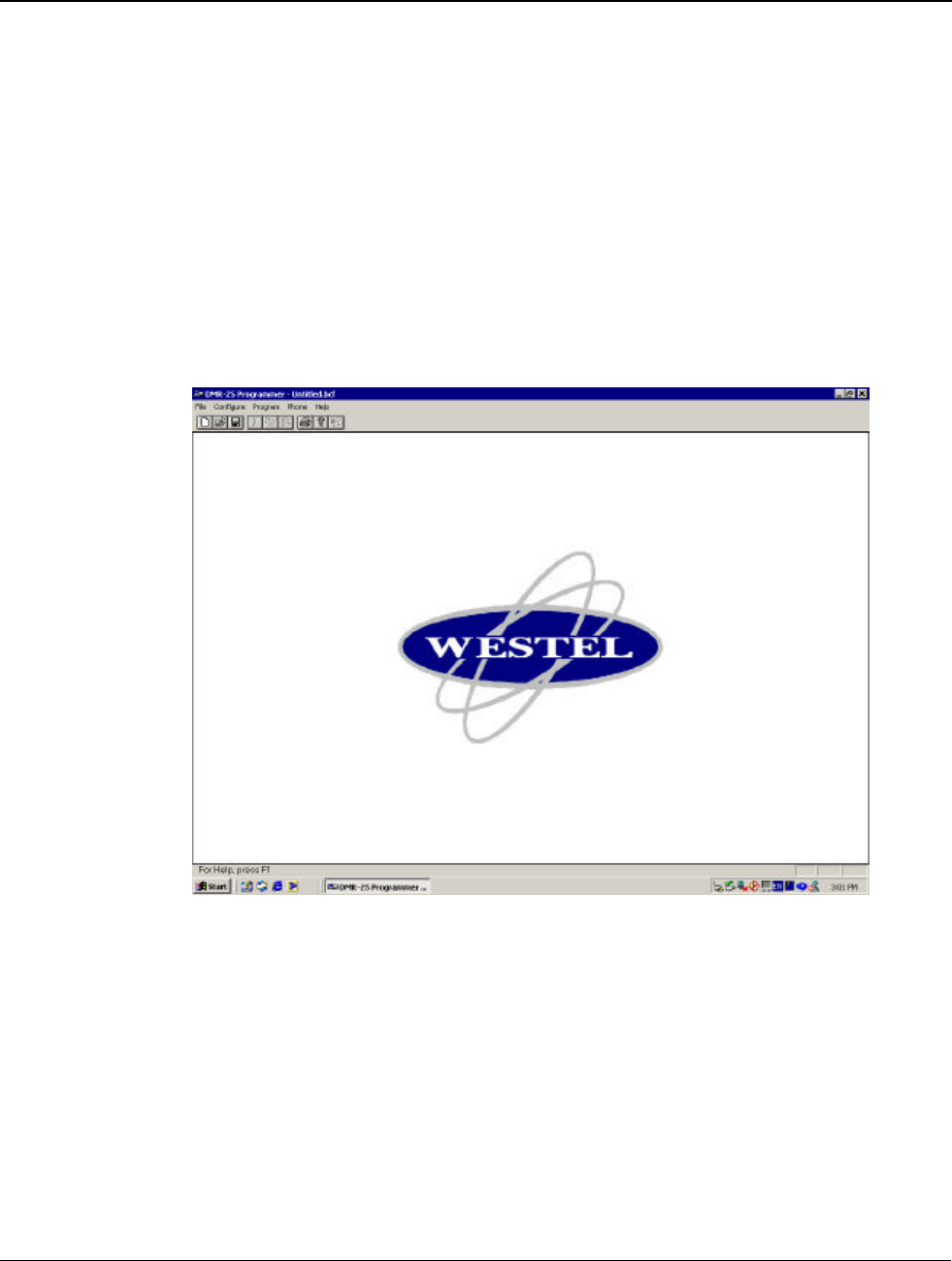
To start the DMR-25 Programmer, select the DMR-25 Programmer icon from the Start | Programs menu.
The DMR-25 Programmer main window will appear as shown in Figure 5-1.
Figure 5-1 DMR-25 Programmer Main Window
5.2.5 Connecting the Programmer to the Transceiver Module
To connect to a DMR Transceiver module:
1. A programming cable (Westel Part number CB-02272) is required. Connect the PC communications
port to be used to the required DMR-25 Transceiver Module RJ-11 serial port connector using the
programming cable.
2. Using the procedure given in Section 3.1, Serial Communications, set the PC communications port used
to connect to the DMR.

Installation and Operator Handbook Programming and Configuration
AMX-MA-00657 Issue: 1.02 (USA) Page 5
The DMR-25 Programmer is now ready to read or write data to or from the DMR-25 module.
5.2.6 Getting Help
The information contained in this manual is available as on-line help as part of the DMR-25 Programmer.
To get help on the DMR-25 Programmer, from the main menu click on the Help pull-down menu and
select Contents, Search or Index as required.
5.2.7 Running the DMR-25 Programmer
There are many configuration options available to the user, some of which depend on the hardware options
installed. Other parameters are operational such as the desired receive and transmit operating frequency
and channel number.
Once the DMR-25 Programmer is installed, the Main Screen provides access to the following dialog boxes:
• File: Generate a New file, Open an existing file, Save, and Save As. Other options allow
the user to Print, Get and Send data.
• Configure: Serial Comms for selection of Serial Port, Modem Commands and Exit Binary
Mode. See Section 3, Configuring Communications.
• Program: Allows user to edit DMR-25 transceiver data using Radio Wide Settings, Channel
Table, Tone Remote Settings, Encryption Settings, Squelch Groups, License Features and
Change Password.
• Phone: Gives the user the ability to dial up over a modem to connect to the Transceiver, and
also hang up when the programming is complete.
• Help: Supplies user with on-line help documentation through Contents, Search,
Using Help and About DMR-25 Programmer.
Initial or exis ting configuration data can be obtained in the following ways:
• File | Open: opens a previously saved file (Will prompt user to save before overwriting currently
opened file).
• File | Get: gets the current file from a DMR-25 Transceiver Module (Will prompt user to save
before overwriting open file).
• File | New: creates a new file via user input dialog boxes.
It is possible to send DMR-25 Transceiver data to the transceiver module by using the File | Send option.
Note that the DMR-25 programmer will reboot the transceiver module after sending the programming
information in order to invoke the new configuration.

Installation and Operator Handbook Programming and Configuration
AMX-MA-00657 Issue: 1.02 (USA) Page 6
5.2.8 Upgrading From TMP to DMR-25
The DMR-25 programmer has new features not available in the TMP programmer. If DMR-25 is used to
upload channel table data which was programmed into a transceiver with TMP, the data elements
describing the new features will be uninitialised, and may need manual editing afterward. By following the
procedure below you can avoid the need for manual editing when upgrading to DMR-25.
DMR-25 Upgrade procedure:
Step 1 - Transceivers with channel tables which were programmed with TMP should be read back with
TMP and the BCF file saved to disk. You can skip this step if you already have a saved BCF file.
Step 2 - Load the BCF file into DMR-25 using the File->Open menu items. When loading the file, the
DMR-25 will set the new features to the default (disabled) state. The new features, in the Channel Settings
dialog are: Channel Name, Squelch System, Squelch Group, CDCSS Invert, Autosense TX, Courtesy
Tone Tail. See section 5.4.1.
Step 3 - If you wish to use any of the new features, update their settings in the Channel Settings dialog .
Particularly check the PTT Delay setting if you enable it, because the format has changed.
Step 4 - The BCF file is now ready to be written back to the Transceiver, or saved to disk.
Installation and Operator Handbook Programming and Configuration
AMX-MA-00657 Issue: 1.02 (USA) Page 7
5.3 Configuring Communications
The Configure pull-down menu allows the DMR-25 programmer to control the PC's serial port and
interface to a modem if desired.
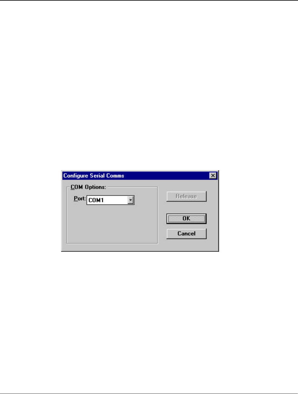
5.3.1 Serial Communications
To set or select the communications port, from the main menu activate the Configure pull-down menu and
select Serial Comms. The Serial Comms dialog box will appear as shown in Figure 5-2.
Select desired port and click OK.
There may be an instance where the serial port is required by another PC application. If so, click
RELEASE so that the other application may use the serial port, without needing to quit the DMR-25
Programmer.
NOTE
Some functions within the DMR-25 Programmer will not work correctly
without serial communications to the transceiver. If in doubt, leave the
serial communication port connected to the DMR-25 Programmer.
Figure 5-2 Serial Comms Dialog Box
Installation and Operator Handbook Programming and Configuration
AMX-MA-00657 Issue: 1.02 (USA) Page 8
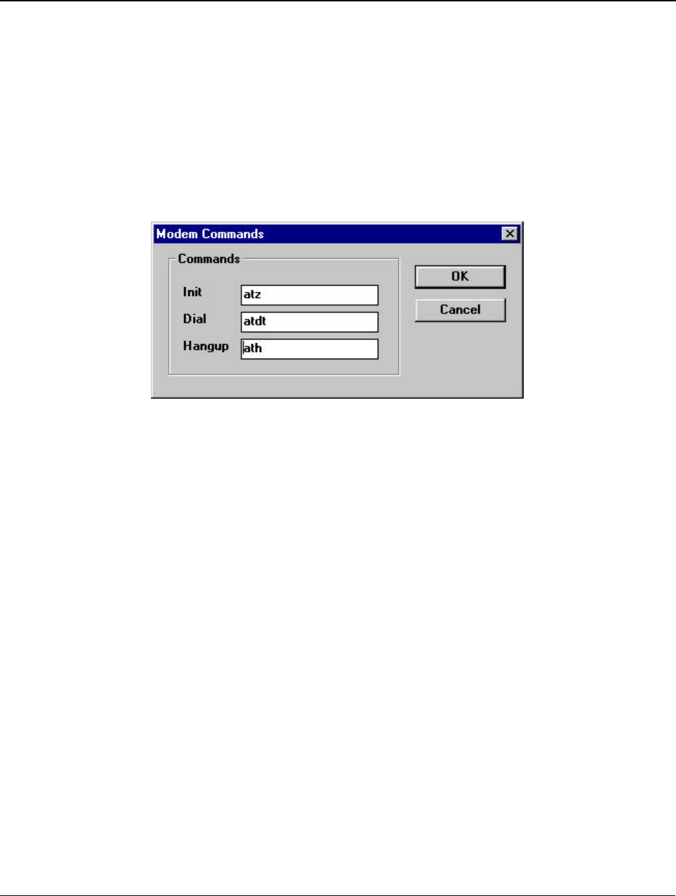
5.3.2 Modem Communications
Consult your modem manual to determine what it requires for initialisation string, dial string, and hangup
string. To set the modem commands used by the DMR-25 Programmer, select the Configure pull-down
menu and select Modem Commands. The Modem Commands dialog box will appear as shown in
Figure 5-3.
Init: The modem initialisation string stores parameters to configure the modem after power up.
Dial: The modem command required before dialing a number.
Hangup: The command required to hangup the modem.
Figure 5-3 Modem Commands Dialog Box
5.3.3 Exit Binary Mode
Configure/Exit Binary Mode: When issuing a File/Send or File/Get command, the PC to DMR-25
communication mechanism on the DMR uses a binary mode. On a failed File/Send or File/Get order, the
DMR may be left in binary mode. The Configure/Exit Binary Mode menu item will, when selected,
force
the DMR back into normal operating mode.
Installation and Operator Handbook Programming and Configuration
AMX-MA-00657 Issue: 1.02 (USA) Page 9
5.4 Programming The Radio
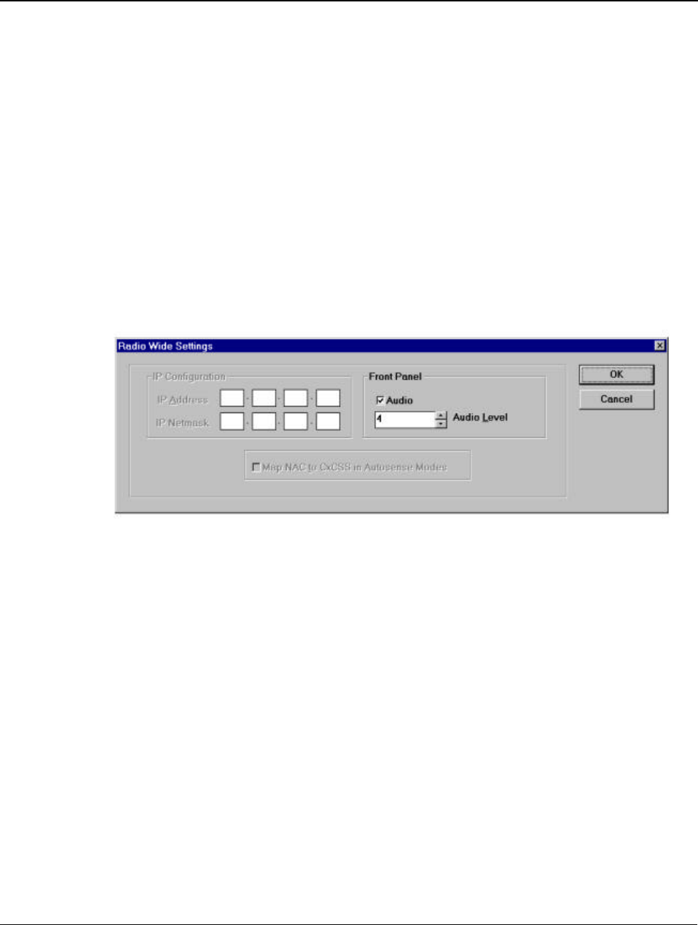
5.4.1 Radio Wide Settings
The Radio Wide Settings dialog box is accessed via Program | Radio Wide Settings. This dialog box
contains general DMR-25 Transceiver parameters as shown in Figure 5-4.
• IP address and netmask parameters for the ethernet interface (future option).
• Front panel audio enable and volume adjustment.
NOTE
This parameter adjusts the audio levels sent to the transceiver front panel RJ45 connector.
Settings made here will have no effect on audio sent to any front panel speaker that is an
integrated part of any DMR radio.
Figure 5-4 Radio Wide Settings Dialog Box
The radio wide settings of the currently open file will be displayed.
To enter IP Configuration parameters: (Future Option)
This function is not currently available but will be included in future releases of the radio software
package.
1. The IP configuration is required whenever the DMR is connected to a LAN using the ethernet facility
on the Interface Module.
2. Point the cursor to a cell where the change is required, click and enter the new parameter. The cursor in
the cell will flash when selected. The cells can be highlighted in sequence using the <Tab> key.
To enter Front Panel Audio parameters:
1. Audio On or Off. Point and click as required to enable or disable audio output to the DMR-25 front
panel audio connector.
2. Audio Level. Click the up or down buttons to select an audio volume level from 0 to 10.(maximum)

Installation and Operator Handbook Programming and Configuration
AMX-MA-00657 Issue: 1.02 (USA) Page 10
If the settings are acceptable, click OK, otherwise click Cancel to close the General Settings dialog box
and the current configuration will not be changed.
Help: Provides access to On-line help for the General Settings dialog box.
Installation and Operator Handbook Programming and Configuration
AMX-MA-00657 Issue: 1.02 (USA) Page 11
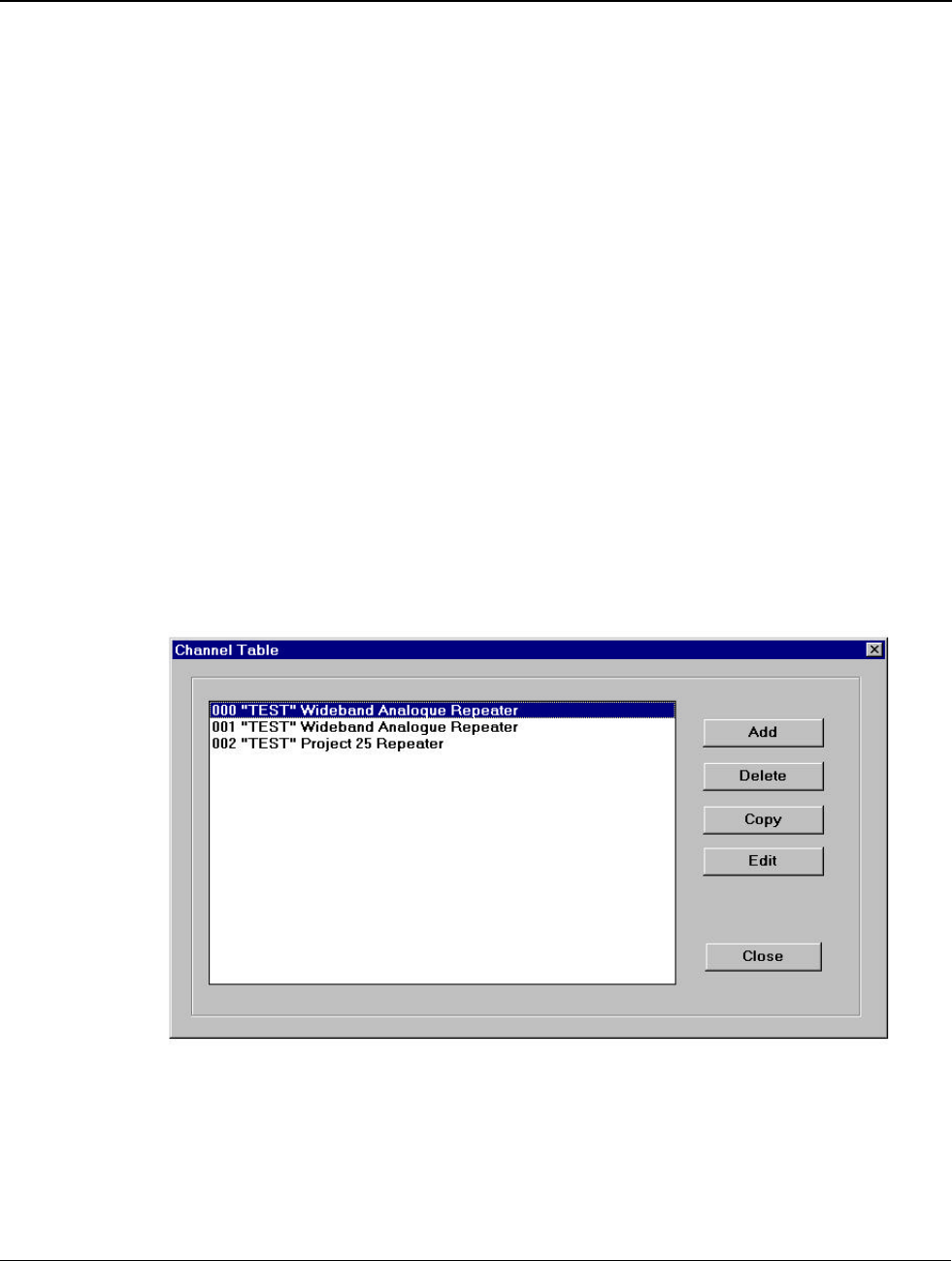
5.4.2 Channel Table
To enter the Channel Table, from the main menu activate the Program pull-down menu and select
Channel Table. The Channel Table dialog box will appear as shown in Figure 5-5.
The table window lists the currently configured channels for the DMR-25 Transceiver. These channels are
sorted in ascending order of the channel number. Listed functions are:
Add: To add a new channel configuration, click ADD and the Channel Settings Dialog Box appears.
Delete: To delete a currently configured channel, highlight the desired channel (left mouse button click on
the channel name) and click DELETE. Several channels may be deleted in one operation, if required.
Copy: To copy a configured channel, highlight the desired channel (left mouse button click on the channel
name) and click COPY. The Copy Channel Dialog Box appears. Enter the new desired channel number
and click OK. If the desired channel number already exists, a new Copy Channel Dialog Box appears
asking if you want to replace the existing configured channel. Click YES to do so. At any stage click
CANCEL to exit the Copy Channel function and return to the Channel Table Dialog Box. The new
channel appears in the Channel Table Dialog Box.
Edit: To edit an existing channel, highlight the required channel (left mouse button click on the channel
name) and click EDIT or double click the left mouse button. The Channel Settings Dialog Box appears
and the channel parameters may be changed.
Close: This closes the Channel Table and returns to the Main Entry Screen of the DMR-25 Programmer.
Figure 5-5 Channel Table Dialog Box
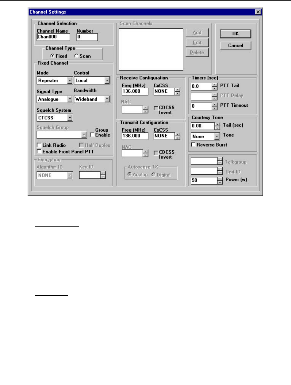
To enter the Channel Settings, either Edit an existing channel or Add a channel from the Channel Table
Window. The Channel Settings dialog box will appear as shown in Figure 5-6.
The channel settings for the selected channel will be displayed in this dialog box.
Installation and Operator Handbook Programming and Configuration
AMX-MA-00657 Issue: 1.02 (USA) Page 12
Figure 5-6 Channel Settings Dialog Box
Channel Selection
Channel Name: The name of the selected channel is shown in the Channel Name window. The channel
name can be changed by overwriting the existing name in the window. The name is limited to 8 characters
in length.
Channel Number: The channel number is displayed in the Channel Number window. When a channel is
created with the Add command, a sequential default channel number appears here and may be edited. The
channel number of established channels may not be edited.
Channel Type
A channel can function as either a Fixed Channel or a Scan Channel. A Fixed Channel is a “real” channel
used to transmit and receive voice messages. A Scan Channel holds a list of Fixed Channels through
which the radio will scan in receive mode. The channel type is selected by clicking the “Fixed” or “Scan”
radio button in the “Channel Type” box.
Fixed Channel

Installation and Operator Handbook Programming and Configuration
AMX-MA-00657 Issue: 1.02 (USA) Page 13
Mode: Click as required to select the operating mo de for the channel between basestation and
repeater. In repeater mode, all valid inbound signals are repeated on the outbound channel. In base-
station mode, valid inbound signals are not repeated.
Control: There are four functions/options that may be selected, Local control, Tone control, Line
control and None.
Local control: is via a DTMF microphone connected to the DMR-25 Transceiver Module audio
connector elsewhere this is described as the front panel connector. DTMF tones can be used to
configure/control the radio.
Tone control: is via an industry standard tone remote control unit connected to the DMR-25
Interface Module line connector. Tone remote tones are used to control the radio.
Line control: uses the rear panel audio port for control but disables tone remote signalling. When a
4-wire interface is used, control is achieved by E+M signalling. When a 2-wire interface is used,
the radio is capable of making and receiving PSTN calls. In this mode call setup, dialing and
cancellation is controlled by the subscriber radio using DTMF or Project 25 signalling.
None: no control option is active.
NOTE
Control options are only available on DMR-25 Radios fitted
with a controller module. Control options will be ignored by
radios which are fitted with the Timing Module as a
replacement for a Controller Card.
Signal Type: Select the channel mode from the list of Analog, Project 25 and Autosense modes.
Bandwidth: This setting determines the peak deviation of the transmitted signal, and the channel
bandwidth used in the receiver. Select the required channel bandwidth from the list, to set
wideband or narrowband analog or autosense operation. Wideband operation should be selected
for use with analog systems employing 25 kHz or 30 kHz channel spacing. Narrowband operation
should be selected for use with analog systems employing 12.5 kHz or 15 kHz channel spacing.
Squelch System: Select the type of analog squelch required between CTCSS and CDCSS.
Group Enable: When selected, the squelch system selection is disabled and a Squelch Group is
required.
Squelch Group: Select from a list of Squelch Groups, which are defined in Program/Squelch
Groups see section 4.5 Squelch Groups. The Squelch System will determine which analog
squelch is used in a squelch Group.
Link Radio: Select to enable the Transceiver Module for cross-band and cross-mode operation.
This selection will be disregarded by the transceiver if it is not licensed to support Link Radio. See
Section 4.6 License Features.
Enable Front Panel PTT: Select to permit transmissions to be made from the microphone
connected to the DMR-25 Transceiver Module Front Panel audio connector.
NOTE

Installation and Operator Handbook Programming and Configuration
AMX-MA-00657 Issue: 1.02 (USA) Page 14
Link Radio cannot be selected when Enable Front
Panel PTT is enabled and vice-versa.
Half Duplex: When half-duplex mode is selected, the receiver is disabled when transmitting and
vice-versa. Half-duplex operation is only available in base-station mode.
Receive/Transmit Configuration
Freq (MHz): Enter the receive and transmit frequency for the selected channel. Note that the VHF
radio frequencies can be set to 1Hz precision. However for the UHF radio, entered frequencies are
internally rounded to a multiple of 5.0 kHz or 6.25 kHz (whichever is nearer) regardless of what is
displayed or entered in the frequency dialog.
When the DMR is operated in full duplex (simultaneous reception and transmission) isolation is
required between the receive and transmit signals to ensure that the receiver is not de-sensed by the
transmitter. The isolation is generally provided by a separate antenna or external RF combining
network. Table 5-2 and Table 5-3 show the minimum and recommended isolation levels for VHF
and UHF-Lo respectively.
Table 5-2 VHF Receive/Transmit Spacing
Receive/Transmit Spacing Minimum
Isolation Recommended Isolation
<600 kHz - Not recommended
600 kHz to 1 MHz 85 dB >100 dB
1 MHz to 2.5 MHz 70 dB >80 dB
>2.5 MHz 60 dB 80 dB
Table 5-3 UHF-Lo Receive/Transmit Spacing
Receive/Transmit Spacing Minimum
Isolation Recommended Isolation
<600 kHz - Not recommended
600 kHz to 1 MHz TBA TBA
1 MHz to 2.5 MHz TBA TBA
>2.5 MHz TBA TBA
Due to harmonics of internal clocks and oscillators degradation of receiver sensitivity may be
experienced on the following specific frequencies, and these frequencies should therefore be
avoided:
140.000000 MHz, 150.000000 MHz, 157.287500 MHz, 160.000000 MHz and 170.000000 MHz.
NAC (Network Access Code). For Project 25 / Autosense operation select the NAC as required,
using hexadecimal (Hex) notation. Receive and transmit NAC may be set independently, or the
transmit NAC may be set to be the same as the received NAC (‘Same as Rx’). If analog channel
mode is selected then these boxes will be disabled. Click on the Up/Down Arrows to
increase/decrease the current NAC value.

Installation and Operator Handbook Programming and Configuration
AMX-MA-00657 Issue: 1.02 (USA) Page 15
The DMR radio can be programmed to un-mute on any NAC by entering the NAC values 0xF7E
and 0xF7F as defined in the Project 25 suite of standards.
CxCSS: Receive and transmit CxCSS may be set independently or the transmit CxCSS may be set
to be the same as the received CxCSS (‘Same as Rx’). If APCO 25 channel mode is selected then
this box will be disabled. Click on the Up/Down Arrows to increase/decrease the current CxCSS
value.
CDCSS Invert: Select to invert the CDCSS encoding string pattern for both receive and transmit.
Autosense TX: Selects the Transmit type (Analog or Digital) when a PTT from the front panel
microphone or rear panel 4w/2w interface has been asserted on a channel whose signal type has
been programmed as "Autosense".
Encryption
Algorithm ID: The DMR-25 Programmer currently supports clear transmission and DES-OFB
algorithm.
Key ID: The Key ID may be a number between 0x0000 and 0xffff.
See Section 4.4 Encryption Settings for details.
Timers
PTT Tail (sec): Enter the amount of time the DMR continues to transmit a carrier signal after the
Press To Talk is released, or click on the up/down arrows to raise or lower the Tail time in 0.1
second increments to a maximum of 9.9 seconds.
PTT Delay (msec): (Applicable to Base-station Mode only) Enter the amount of time the Tx/Rx
changeover relay is allowed to stabilize before RF power is applied, or click on the up/down arrows
to raise or lower the Delay time in 1 millisecond increments to a maximum of 99ms. Set to zero if
no changeover relay is used.
PTT Timeout (sec): Enter the maximum duration of continuous transmission in seconds, or click
on the up/down arrows to raise or lower the Timeout in 1 second increments to a maximum of 255
seconds. If no transmission length timer is required, set to zero.
Courtesy Tone
Courtesy tone is only applicable in repeater mode.
Tail (sec): Enter the desired duration of the courtesy tone to follow analogue voice transmissions
initiated from the front panel microphone or rear panel 2w/4w interface, or click on the up/down
arrows to raise or lower the Tail time in 10 millisecond increments to a maximum of 9.99s.
Tone (Hz): There are four options available, None, 400Hz, 1000Hz and 2500Hz.
Reverse Burst: Reverse Burst is a feature designed to minimise the squelch crash at the end on an
analogue transmission. If the reverse burst check box is selected in an analogue transmit mode then
at the end of a transmission the CTCSS tone phase will be inverted for CTCSS channels or the
CDCSS "turn-off" signal will be transmitted for CDCSS channels as described in TIA/EIA 603.
When this box is selected, the Courtesy Tone tail setting determines the burst length, and Tone
Installation and Operator Handbook Programming and Configuration
AMX-MA-00657 Issue: 1.02 (USA) Page 16
setting is ignored. The tail time should be selected to optimise the performance of the particular
analog mobile used in a system.
General
Talk Group ID: Select or enter the Talk Group ID for Project 25 transmissions from the DMR in
basestation mode.
Unit ID: Select Unit ID for the Base-station Unit.
Power (Watts): Enter the transmit output power for the channel or click on the up/down arrows to
raise or lower the output power in 1 W increments. Because internal communication with the PA is
slow, around 30 seconds will elapse after radio startup before this setting becomes active. During
those 30 seconds, the transmitter, if keyed, will transmit at full power.
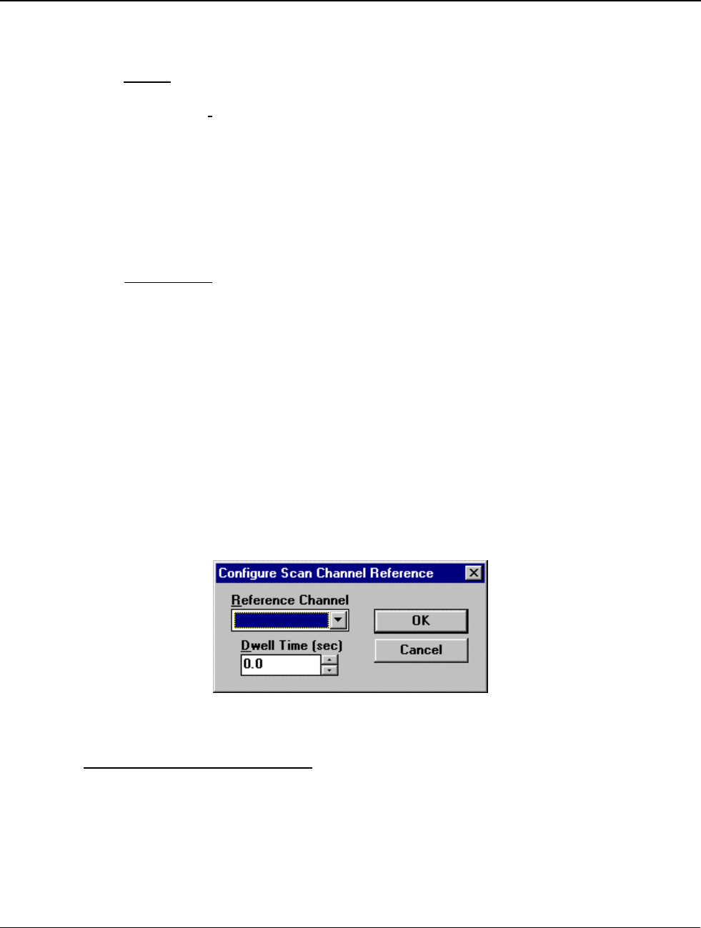
Scan Channels
A scan channel consists of two or more fixed channels. The DMR-25 will step through the list of
fixed channels until it finds one with a valid receive signal. The Channel Settings Dialog Box
displays a list of fixed channels with their dwell times. Use the Add, Edit and Delete buttons to
manage this list.
Add: Adds a reference channel to the selected scan channel list using the Configure Scan
Channel Reference Dialog Box shown in Figure 5-7. Select a fixed channel in the Reference
Channel field and nominate a Dwell Time. Dwell Time is the period, in seconds, for which the
DMR will monitor a particular reference channel given ceased activity on that channel. The selected
reference channel is then added to the scan channel when the OK button is clicked or discarded if
the Cancel button is clicked.
Edit: Changes the parameters of a preconfigured fixed channel.
Delete: Deletes the highlighted reference channel from the Scan Channel list.
Figure 5-7 Configure Scan Channel Reference Dialog Box
Channel Settings Dialog Box Controls:
OK: Returns to the Channel Table Dialog Box, updating the parameters of the selected channel.
Cancel: Returns to the Channel Table Dialog Box, without changing the parameters of the selected
channel.
Table 5-4 lists the applicable setting ranges and brief descriptions of the channel parameters.

Installation and Operator Handbook Programming and Configuration
AMX-MA-00657 Issue: 1.02 (USA) Page 17
Table 5-4 Channel Parameters and Limits
Parameter Range
Channel Selection Channel 0 to Channel 511 as defined in Program/Channel Table
Channel Type Fixed or scan
Signal Type Project 25, Analog FM (CTCSS or CDCSS), Autosense (Project 25 and Analog)
Channel Mode Basestation or Repeater.
Spacing Wide or Narrow band
Frequency in MHz VHF 136-174 MHz or UHF 400-470 MHz.
Network access code
(NAC) Receive :3 digit hexadecimal
Transmit : 3 digit hexadecimal, or ‘same as receive’
CxCSS Receive : Tones and codes according to TIA 603, or ‘any’
Transmit : Tones and codes according to TIA 603, ‘none’ or ‘same as receive’
Talk group ID 4 digit hexadecimal 0x0001 to 0xFFFF (All Talk-groups)
Encryption algorithm DES–OFB or None
Encryption key ID Up to 16 key IDs (labeled 0x0000 to 0xFFFF) as defined in Program/Encryption
Settings
Control mode Repeater, Basestation local control, Basestation tone control, Line control and
None (no control)
Disable front panel PTT
Enabled/Disabled
Link radio Enabled/Disabled
Unit ID 0 through to 0xFFFFFF
PTT Timeout 0 to 255 seconds
PTT Tail 0.0 to 9.9 seconds
PTT Delay 0.0 to 0.099 seconds
Courtesy Tail 0.00 to 9.99 seconds
Courtesy Tone None/400Hz/1000Hz/2500Hz
Power 60 W Pas : 5 to 60 W (134 – 160 MHz), 5 to 50 W (160-174 MHz)
125 W PAs : 12 to 125 W
Number of Referenced
Channels within a Scan
Channel
1 to 8 fixed channels
Dwell time 0.0 to 9.9 seconds

Installation and Operator Handbook Programming and Configuration
AMX-MA-00657 Issue: 1.02 (USA) Page 18
5.4.3 Tone Remote Settings
Using the Tone Remote Properties the following functions may be allocated to tones used by industry
standard tone remote units:
• Increase audio level
• Decrease audio level
• Change to Tone Remote controlled channel
Selecting Program/Tone Remote Settings, the Tone Remote Settings Dialog Box will appear as shown in
Figure 5-8. This box lists the currently configured tone signals with their appropriate function.
Figure 5-8 Tone Remote Dialog Box
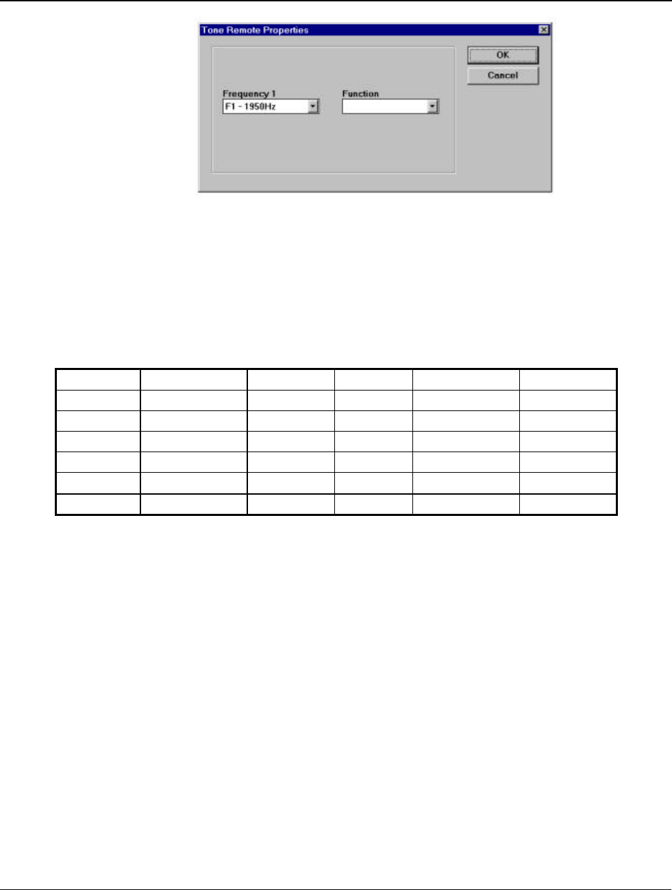
Add: When selected, the Tone Remote Properties appears as shown in Figure 5-9. Select a function tone
(F1 – F12). When assigning a function, the pull-down window lists the appropriate channels, (eg. Fixed
channels with Tone control are assigned as tone remote channels) and increase/decrease audio level
functions. Choose a function and click OK. The new function will now be displayed in the Tone Remote
Settings Dialog Box. Otherwise click CANCEL and the Tone Remote Settings will remain unchanged.
Edit: To edit a particular Tone Remote function from the Tone Remote Settings Dialog Box, either
highlight the appropriate function and click EDIT or simply double click the function. This will display
the Tone Remote Properties Dialog Box containing the functions current properties.
Delete: To delete a particular tone remote function, highlight the required function and click DELETE.
When satisfied with the tone remote function settings, click OK. Otherwise, click CANCEL to ignore
changes.
Installation and Operator Handbook Programming and Configuration
AMX-MA-00657 Issue: 1.02 (USA) Page 19
Figure 5-9 Tone Remote Properties
F1 may be allocated to Increase Audio and Change Channel. F2 may be allocated to Decrease Audio and
Change Channel. F3 – F12 may only be allocated to Change Channel functions. The DMR Tone Remote
functions are pre-programmed to detect the following industry standard tones. The function tone
frequencies are listed in Table 5-5.
Table 5-5 Function Tone Frequencies
Function Frequency (Hz) Level (dBm) Function Frequency (Hz) Level (dBm)
F1 1950 0 F2 1850 0
F3 1750 0 F4 1650 0
F5 1550 0 F6 1450 0
F7 1350 0 F8 1250 0
F9 1150 0 F10 1050 0
F11 950 0 F12 850 0
Installation and Operator Handbook Programming and Configuration
AMX-MA-00657 Issue: 1.02 (USA) Page 20
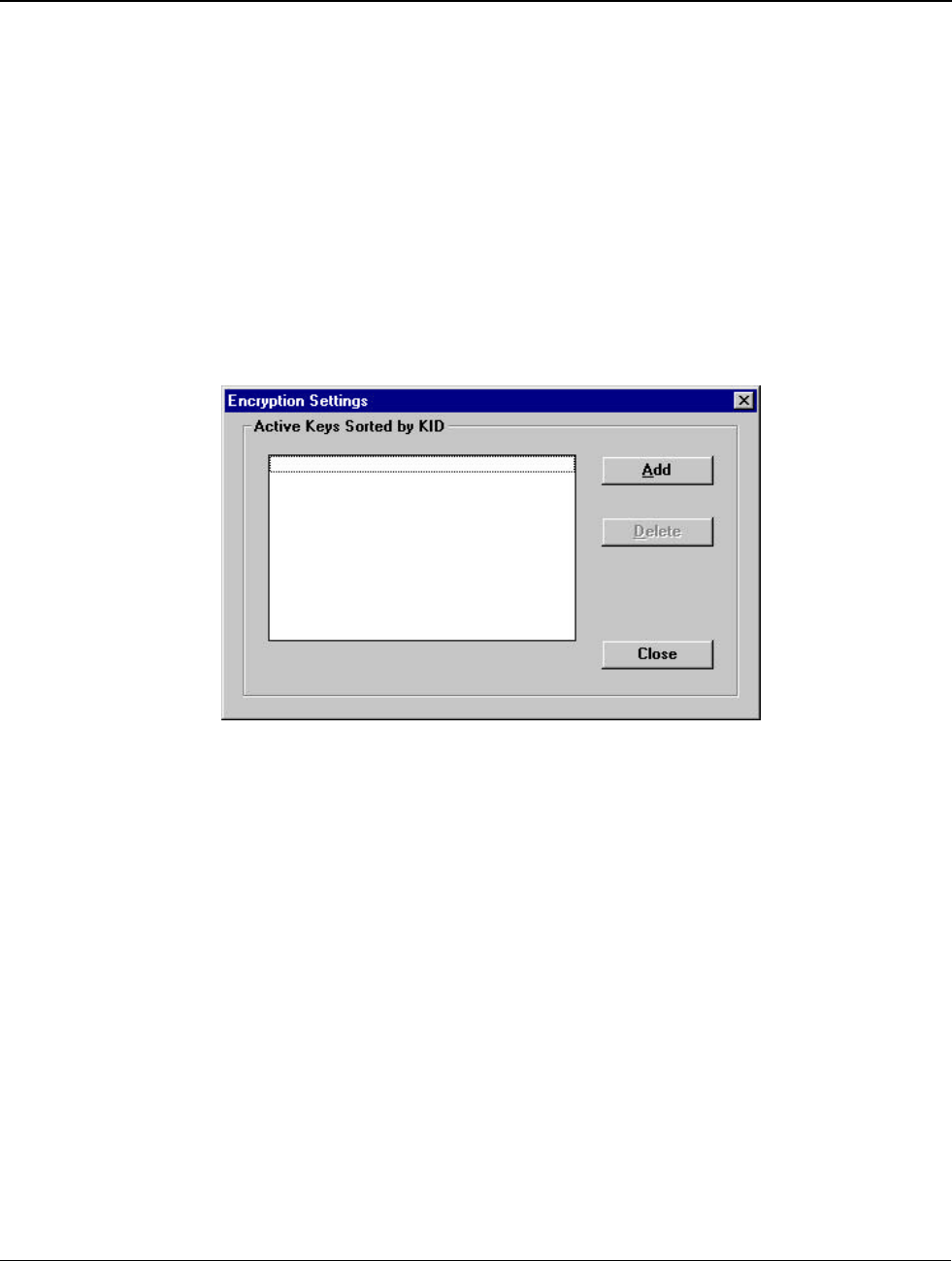
5.4.4 Encryption Settings
Program/Encryption Settings opens the Encryption Settings Dialog Box as shown in Figure 5-10 listing the
currently configured Encryption keys. If an encryption key is entered, and its Key ID matches that of an
incoming transmission, the key will be used to decrypt the transmission. Up to 16 keys can be entered, and
the transmission will automatically select the correct key which matches the incoming Key ID.
NOTES
1. Encryption Keys, once configured, cannot be reviewed.
2. If the radio is not licensed for the encryption feature, the
encryption keys will be ignored (see Section 7 License
Features).
Figure 5-10 Encryption Settings Dialog Box
To Add an Encryption Key click ADD and the Add Key Dialog Box appears as shown in Figure 5-11.
The required key is entered into the eight 2-hex-digit boxes using the Tab key to move between boxes.
Note that each 2-hex-digit code must have odd parity. The DMR-25 programmer will check and report any
errors of the entered encryption key. Next, enter a Key ID between 0x0000 and 0xFFFF. When the
desired Encryption Key and Key ID are entered, click OK and the new key will be listed in the Encryption
Settings Dialog Box.
Clear Key: In the Add Key Dialog Box, an entered key can be cleared by clicking the Clear Key button.
Generate Random Key: To add a random key, click Generate Random Key button and assign a Key ID.
At any stage, the CANCEL button can be clicked and the key will not be added to the list.
Delete: To delete an existing Encryption Key, highlight the desired key and click DELETE.
Close: When satisfied with the list of Encryption Keys, click CLOSE in the Encryption Settings Dialog
Box.

Installation and Operator Handbook Programming and Configuration
AMX-MA-00657 Issue: 1.02 (USA) Page 21
Figure 5-11 Add Key Dialog Box
Installation and Operator Handbook Programming and Configuration
AMX-MA-00657 Issue: 1.02 (USA) Page 22
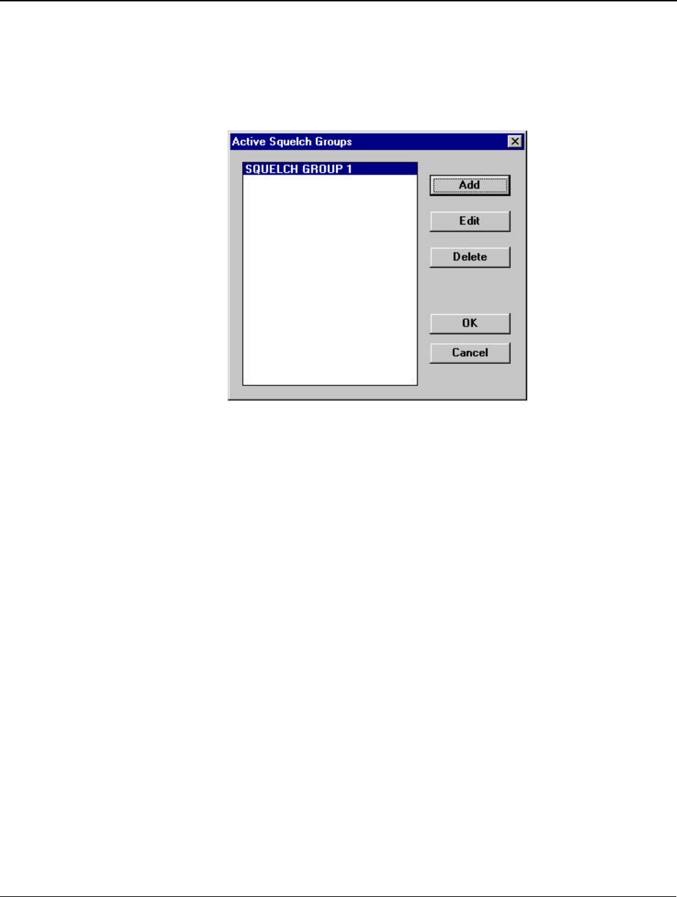
5.4.5 Squelch Groups
Program/Squelch Groups will display the Active Squelch Groups Dialog Box as shown in Figure 5-12.
This lists the currently configured Squelch Groups. Groups of squelch tones are used to allow a repeater to
retransmit a signal containing any one of a number of different squelch tones or codes.
Figure 5-12 Active Squelch Groups Dialog Box
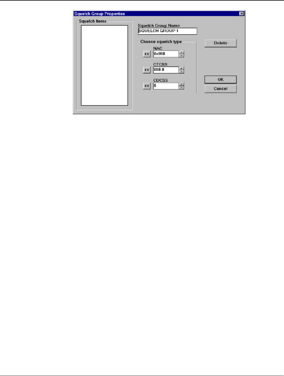
Add: To add a squelch group, click ADD and the Squelch Group Properties Dialog Box appears as
shown in Figure 5-13. Enter a name for the new squelch group in the Squelch Group Name Field. Then,
by clicking the up/down arrows, select the desired squelch value for the squelch system and click the
appropriate Left Arrow to add the selection to the list.
NOTE
Multiple values for the same squelch system, and multiple squelch
systems, with the exception of the CDCSS and CTCSS case, can co-
exist in the same squelch group. The DMR-25 radio will use the
appropriate values in the group for the selected channel.
Items within the list can be deleted by highlighting the desired item and clicking DELETE. When
satisfied with the list click OK and the new list is entered as a new squelch group and displayed in the
Active Squelch Groups Dialog Box. Alternatively, click CANCEL and all additions and/or changes are
ignored.
Edit: Squelch groups can be edited by either double clicking on the appropriate group or by highlighting
the group and clicking EDIT. The Squelch Group Properties Dialog Box displays the configuration of
the selected group where items can be added, altered or deleted as required.
Delete: Existing squelch groups can be deleted by highlighting the required group and clicking DELETE.
When the list of groups is finalised, click OK or click CANCEL and the changes will be ignored.
Installation and Operator Handbook Programming and Configuration
AMX-MA-00657 Issue: 1.02 (USA) Page 23
Figure 5-13 Squelch Groups Dialog Box
Installation and Operator Handbook Programming and Configuration
AMX-MA-00657 Issue: 1.02 (USA) Page 24
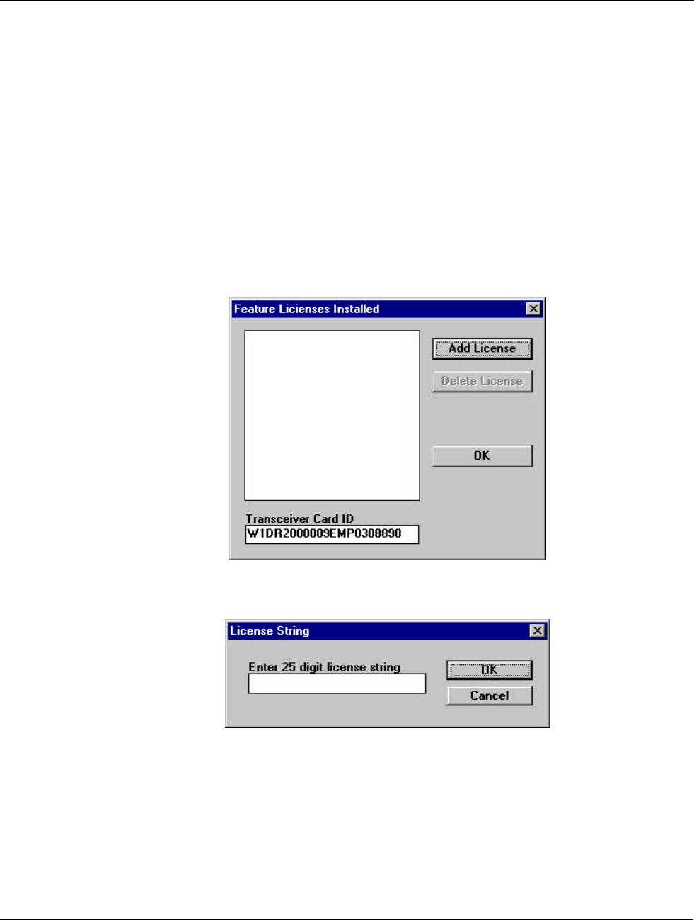
5.4.6 License Features
Although all of the software described in this manual is contained in the DMR-25 transceiver software,
some features require a license key before they become active. If no keys are present, the transceiver
software will ignore any settings made via the DMR-25 Programmer which require a license key. Current
license key features are Link (Section 5.4.2) and Encryption (Section 5.4.4).
Licenses can be displayed in Program/License Features as shown in Figure 5-14. Licenses cannot be
added or deleted "off-line". The DMR-25 Programmer must be connected to a transceiver to use this
feature. Licenses can be added by clicking Add License where a 25-digit string should be entered as
shown in Figure 5-15. The transceiver license string is updated immediately "OK" is clicked in the dialog.
Contact your supplier to obtain the license string.
Licenses can be deleted by highlighting the required license and clicking Delete License. When satisfied
with the license structure, click OK to return to the DMR-25 programmer main screen.
Figure 5-14 License Features Dialog Boxes
Figure 5-15 Add License Dialog Boxes
Installation and Operator Handbook Programming and Configuration
AMX-MA-00657 Issue: 1.02 (USA) Page 25
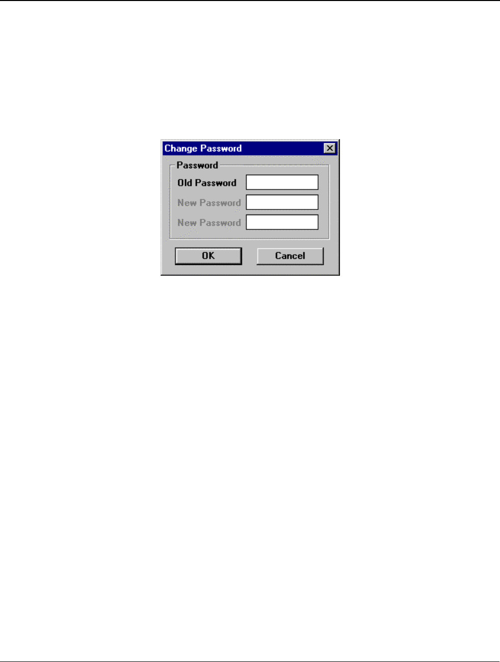
5.4.7 Change Password
The programming details of a DMR-25 Radio may be protected from unauthorised use by the inclusion of
a password. Setting a password in the radio will mean that the programming information of the radio
cannot be viewed or changed without first entering the correct password.
To change the password, from the main menu activate the Program pull-down menu and select Change
Passwords. The Change Password dialog box will appear as shown in Figure 5-16. Like license strings,
passwords can only be changed if the DMR-25 Programmer is connected to a transciever.
Figure 5-16 Change Password Dialog Box
Enter the old password, followed by the desired new one. If no password is currently set, leave the “Old
Password” field empty. Enter the new password again in the bottom field for verification and click OK.
The Tab key may be used to move between the text boxes. To remove the password from the radio, enter
the old password in the “Old Password” field and leave the “New Password” fields empty.
NOTE
Transceivers are shipped without active passwords and no password is
required for normal operation. Earlier transceivers were shipped with
the default password “1234”. If the DMR-25 prompts for a password
unexpectedly, try “1234”.
If you forget the password for a radio, contact your Westel distributor.