Westel Wireless Systems C100063 UHF Base Station Transceiver User Manual 656 002
Westel Wireless Systems Pty Ltd UHF Base Station Transceiver 656 002
Contents
MANUAL DIAGNOSTIC MONITER

Installation and Operator Handbook DRB-25 Diagnostics Monitor
AMX-MA-00656 Issue 0.02 (USA) 1
TABLE OF CONTENTS
Page
6 DRB-25 DIAGNOSTICS MONITOR 2
6.1 OVERVIEW 2
6.2 GETTING STARTED 2
6.2.1 System requirements 2
6.2.2 Making a Backup Copy of the DRB-25 Diagnostic Monitor Disk 2
6.2.3 Installing the DRB-25 Diagnostic Monitor Software 2
6.2.4 Starting DRB-25 Diagnostic Monitor for the First Time 3
6.2.5 Connecting the DRB-25 Diagnostic Monitor to the Controller Module 3
6.2.6 Getting Help 4
6.3 RUNNING THE DRB-25 DIAGNOSTIC MONITOR 4
6.3.1 Configuration 4
6.3.2 Configure Communications 4
6.3.3 Configure Polling Interval 6
6.3.4 Status/Test 6
6.3.5 Alarms 8
6.3.6 Test 9
6.3.7 Changing the Password 12
LIST OF FIGURES
6-1 DRB-25 Diagnostic Monitor Main Window..........................................................................................................................3
6-2 Configure Comms Dialog Box..................................................................................................................................................5
6-3 Polling Interval Dialog Box.......................................................................................................................................................6
6-4 Radio 1 and Radio 2 Status Dialog Box..................................................................................................................................8
6-5 Alarms Dialog Box.....................................................................................................................................................................9
6-6 Password Dialog Box..................................................................................................................................................................9
6-7 Test Radio Dialog Box.............................................................................................................................................................11
6-8 Change Password Dialog Box.................................................................................................................................................12
LIST OF TABLES
6-1 System Requirements .................................................................................................................................................................2
6-2 Communications Parameters .....................................................................................................................................................5

Installation and Operator Handbook DRB-25 Diagnostics Monitor
AMX-MA-00656 Issue 0.02 (USA) 2
6 DRB-25 DIAGNOSTICS MONITOR
6.1 OVERVIEW
DRB-25 Diagnostics Monitor is a Windows based software application running on an IBM compatible
PC connected to the front panel RS-232 port (RJ-11) on the Controller Module of the DRB-25. ZDM allows
an operator to monitor the activity and status of both transceiver modules together with the alarm status of all
DRB-25 modules.
6.2 GETTING STARTED
6.2.1 System requirements
The minimum system requirements for operation of the DRB-25 Diagnostics Monitor software application
are given in Table 6-1.
Table 6-1 System Requirements
Component Minimum Recommended
Computer 80386 Intel Pentium at 100 MHz
Operating system Windows 3.1 Windows 95 or Windows NT
RAM 4 Mb 16 Mb
Hard disc free space 1.5 Mb 10 Mb
Display type Super VGA Super VGA
Display resolution 640 x 480 pixels 1024 x 768 pixels
6.2.2 Making a Backup Copy of the DRB-25 Diagnostic Monitor Disk
To prevent accidental erasing or overwriting of files, it is recommended that a write-protected backup copy of
the DRB-25 Diagnostics Monitor program disk be made prior to installation.
6.2.3 Installing the DRB-25 Diagnostic Monitor Software
The following steps assume that the DRB-25 Diagnostic Monitor software is being installed from diskette
drive A:\ or CD ROM on to hard drive D:\. If other drives are being used, make the appropriate substitutions
in the following procedure.
To install the DRB-25 Diagnostic Monitor software application:
1. Start Windows
2. Place the DRB-25 Diagnostic Monitor distribution diskette in a floppy disk drive on the PC or if the
software was distributed on CDROM, place the CD in the CDROM drive.
3. Run File Manager (Windows 3.1) or Explorer (Windows98 and NT), and display the files on the
distribution medium.
Installation and Operator Handbook DRB-25 Diagnostics Monitor
AMX-MA-00656 Issue 0.02 (USA) 3
4. Double-click on the file “setup.exe”. For floppy disk distributions this will be a top-level file, for
CDROMS it may be located in a subdirectory named “disk1”.
5. Follow the instructions given by the Setup dialog boxes.
If installation problems occur then contact the supplier.
6.2.4 Starting DRB-25 Diagnostic Monitor for the First Time
To start the DRB-25 Diagnostic Monitor, select the ZDM icon from the Start | Programs menu.
The DRB-25 Diagnostic Monitor main window will appear as shown in Figure 6.1.
Figure 6-1 DRB-25 Diagnostic Monitor Main Window
6.2.5 Connecting the DRB-25 Diagnostic Monitor to the Controller Module
To connect to a Controller Module:
1. A DRB-25 Programming Cable (ADI Part number AMX-CB-02272) is required. Connect the PC
communications port to be used to the DRB-25 Controller Module RJ-11 serial port connector using the
cable.
2. The DRB-25 Diagnostic Monitor will attempt to automatically establish communications with the
Controller Module. If this is successful the status dialog boxes will open automatically. If not the
Configure Comms dialog box will be opened.
3. Using the procedure given in Section “Configuring Communications”, set the PC communications port
used to connect to the DRB-25, and the PC communication parameters required for the Controller Module.
Installation and Operator Handbook DRB-25 Diagnostics Monitor
AMX-MA-00656 Issue 0.02 (USA) 4
The Controller Module default communications settings are 9600 baud, 8 data bits, 1 stop bit and no parity
(8N1).
6.2.6 Getting Help
To get help on the Transceiver Module programmer, from the main menu activate the Help pull-down menu
and select Contents, Search or Index as required.
6.3 RUNNING THE DRB-25 DIAGNOSTIC MONITOR
Once DRB-25 Diagnostic Monitor is installed it will attempt establish communications with the Controller
Module and if successful the status dialog boxes will open automatically. The Main Screen provides access to
the following dialog boxes.
• File menu: The only option available is Exit.
• Configure: Dialog boxes for Configure Communications and Polling Interval.
• Status/Test: Status dialog boxes for Radio 1 Status, Radio 2 Status and Alarms; Test dialog boxes
for Radio 1 Test, Radio 2 Test and Change Test Password
• Help dialog box.
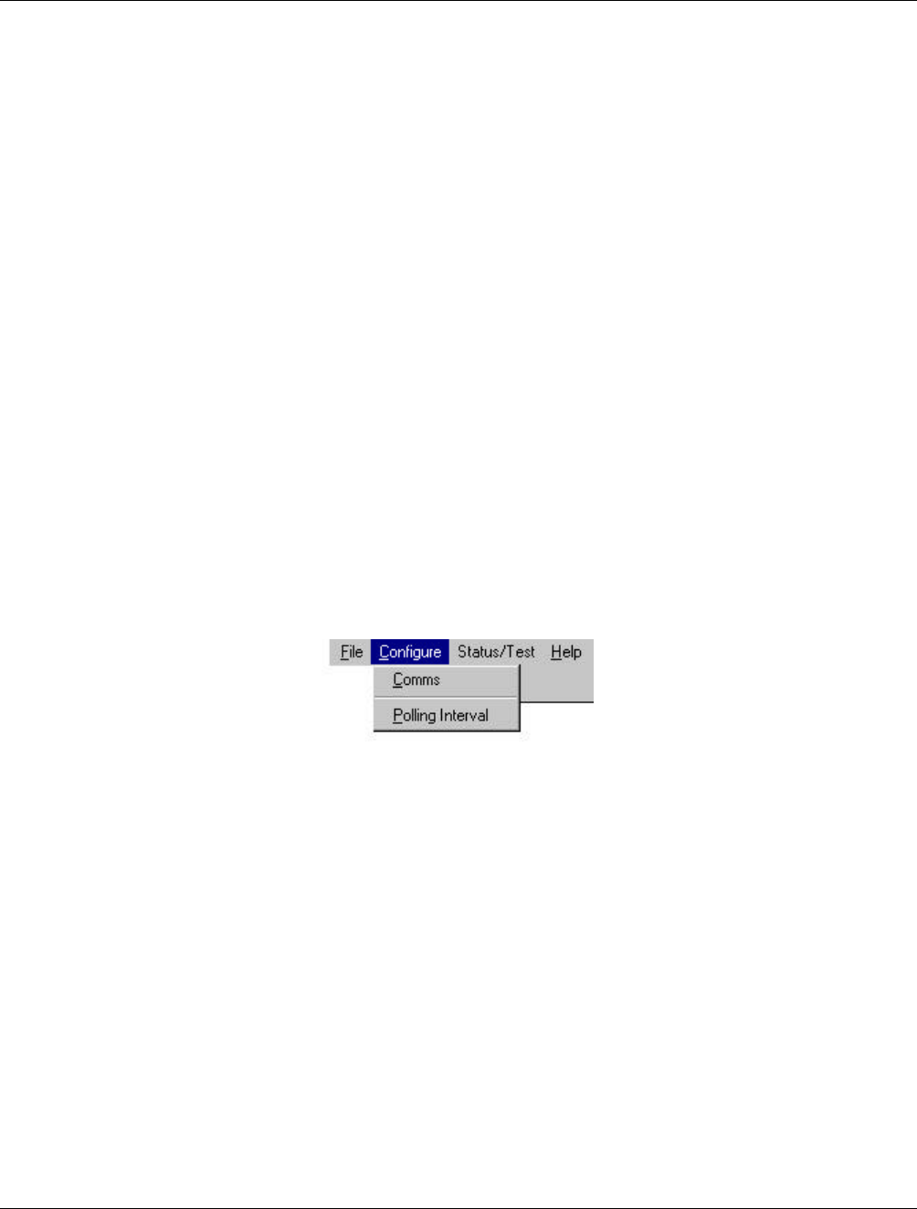
6.3.1 Configuration
From the main screen the Configure Menu gives access to configuring communication parameters and the
polling interval.
6.3.2 Configure Communications
The user will be prompted for Configure Communications dialog box if the DRB-25 Diagnostic Monitor is
unable to establish communications with the Controller Module or whenever Configure | Comms is selected
The following communications parameters may be set:
• Flow control (Xon or Xoff).
• Communications Port.
• Data Bits.
• Baud rate.
• Stop Bits.
• Parity.
Installation and Operator Handbook DRB-25 Diagnostics Monitor
AMX-MA-00656 Issue 0.02 (USA) 5
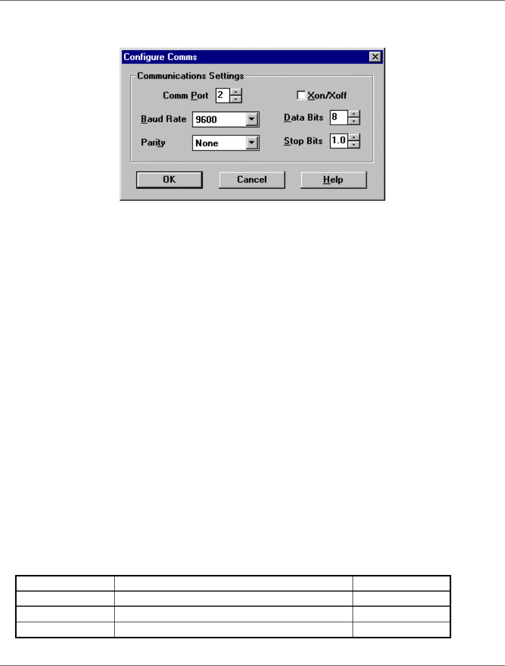
To configure communications parameters, from the main menu activate the Program pull-down menu and
select Configure Comms. The Configure Comms dialog box will appear as shown in Figure 6-2.
Figure 6-2 Configure Comms Dialog Box
The communications settings of the currently open file will be displayed. Where there is no file open, the
default settings will be displayed. Table 6-2 lists the default communications settings.
To enter parameters:
1. Place the cursor on a cell where a change is required. The cursor will flash in the cell if placed there by use
of the mouse. The cell will be highlighted if the Tab key is used.
2. Delete the existing value in the cell and enter the new parameter.
3. Click OK to update the current configuration.
OK
Closes the Configure Comms dialog box and writes any newly-entered communications data to the BP
application’s .INI file.
Cancel
Closes the Configure Comms dialog box without writing data to the .INI file..
Help
Provides access to on-line help on the Configure Comms dialog box.
Table 6-2 lists the applicable ranges and defaults for the communications parameters.
Table 6-2 Communications Parameters
Parameter Range/Description Default
Flow Control Xon or Xoff X off
Baud Rate 1200, 2400, 4800, 9600, 14400, 19200 and 28800 9600
Com Port 1,2,3 etc. 1
Installation and Operator Handbook DRB-25 Diagnostics Monitor
AMX-MA-00656 Issue 0.02 (USA) 6
Parameter Range/Description Default
Data Bits 7 to 10 8
Parity Odd, Even, None. O
Stop bits 1, 1.5, 2 1
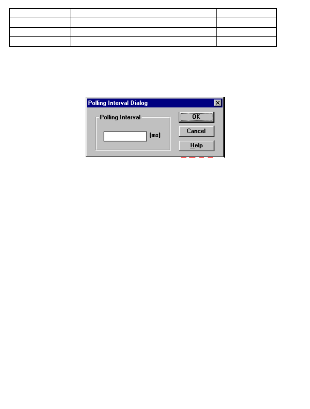
6.3.3 Configure Polling Interval
The Configure | Polling Interval dialog box enables the user to set the interval at which the DRB-25
Diagnostic Monitor polls the Controller card for status information. The default polling interval is 1000ms.
The Polling Interval Dialog box will appear as shown in Figure 6-3.
Figure 6-3 Polling Interval Dialog Box
To enter/change parameters:
1. Place the cursor in the cell
2. Delete the existing value in the cell and enter the new parameter.
3. Click OK to update the current configuration.
OK
Closes the Polling Interval dialog box and writes any newly-entered communications data to the ZDM
application’s .INI file.
Cancel
Closes the Polling Interval dialog box without writing data to the .INI file..
Help
Provides access to on-line help on the Polling Interval dialog box.
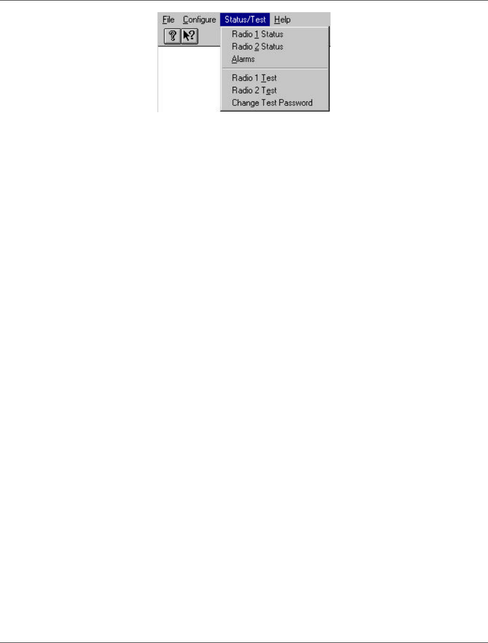
6.3.4 Status/Test
From the Main Menu the Status/Test gives access to the status dialog boxes for Radio 1, Radio 2 and Alarms
and the test dialog boxes for Radio 1, Radio 2. It also includes provision to change the password used to
access the test functions.
Installation and Operator Handbook DRB-25 Diagnostics Monitor
AMX-MA-00656 Issue 0.02 (USA) 7
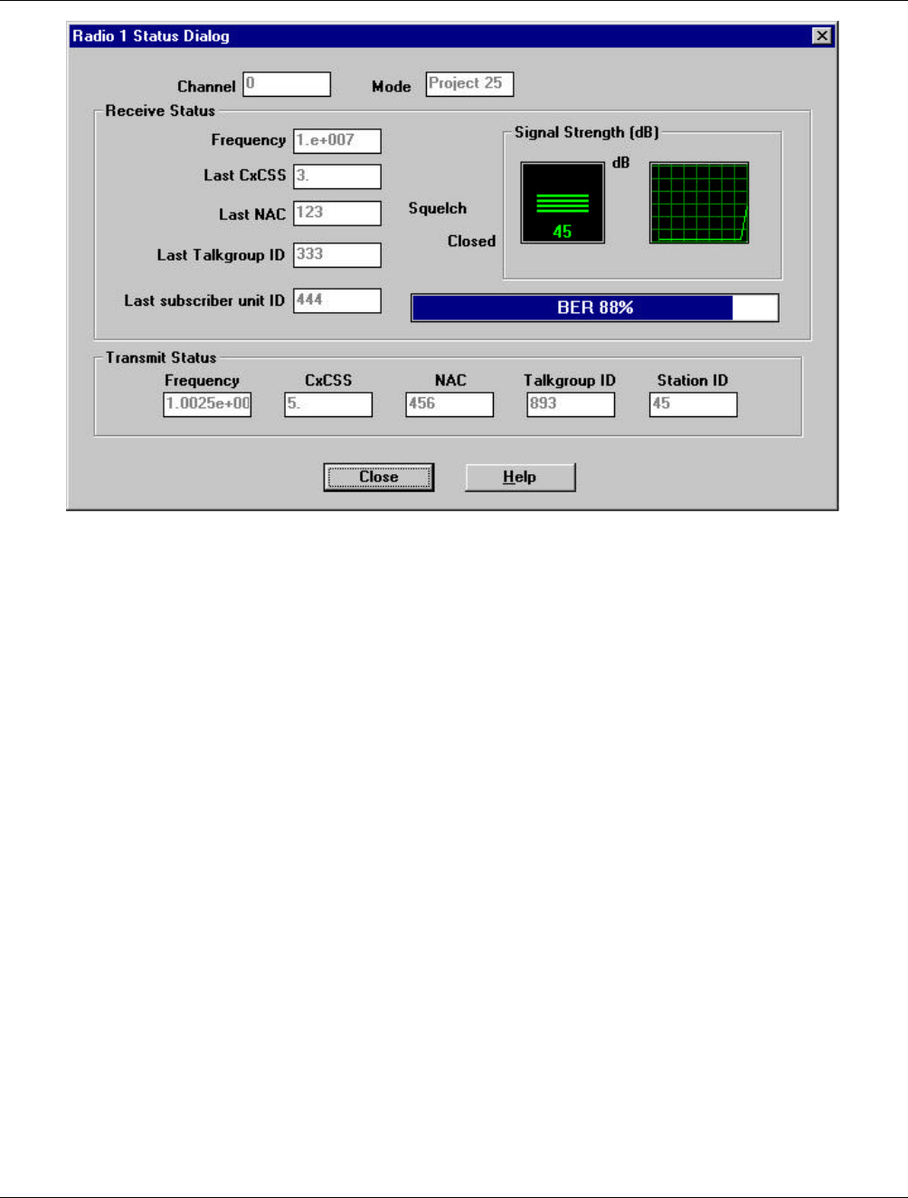
Radio Status
The status boxes for Radio 1 and Radio 2 provide identical parameters for the two DRB-25 transceiver
modules:
• Channel : The current channel in use
• Mode : the current mode
• Frequency : the current receive and transmit frequencies
• Signal Strength : the current receive signal level
• BER : for digital signals the current BER (%)
• Squelch : open/closed
• NAC : for digital signals the current transmit and receive NAC
• CxCSS : for analog signals the current CTCSS or CDCSS
• Talk Group ID : for digital signals the current receive and transmit TGID
• Station ID : the station ID/FCC callsign
• Last subscriber ID : for digital signals the identity of the last subscriber unit heard.
The Radio Status dialog box will appear as shown in Figure 6-4.
Installation and Operator Handbook DRB-25 Diagnostics Monitor
AMX-MA-00656 Issue 0.02 (USA) 8
Figure 6-4 Radio 1 and Radio 2 Status Dialog Box
The status parameters are updated at the rate specified in the Configure | Polling Interval dialog box.
Close
Closes the Radio Status dialog box.
Help
Provides access to On-line help for the Radio Status dialog box.
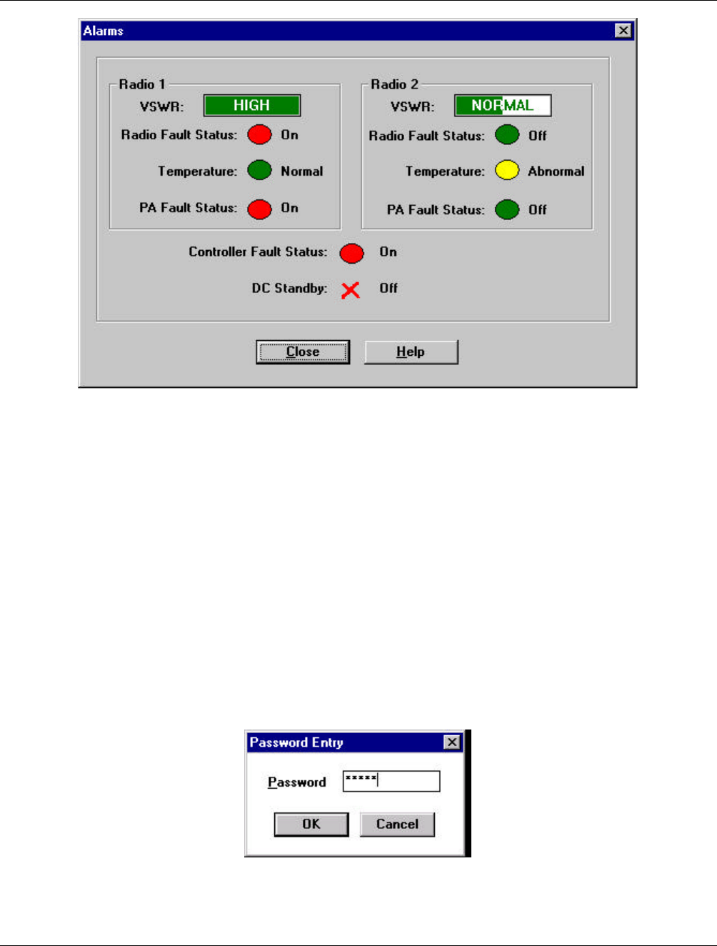
6.3.5 Alarms
The Alarms dialog box shows the status of the following DRB-25 parameters and alarms:
• VSWR hi/lo/normal
• Temperature critical/abnormal/normal
• Radio Fault Status on/off
• PA Fault on/off
• Controller Fault set/clear
• DC Standby on/off
The Alarms dialog box will appear as shown in Figure 6-5.
Installation and Operator Handbook DRB-25 Diagnostics Monitor
AMX-MA-00656 Issue 0.02 (USA) 9
Figure 6-5 Alarms Dialog Box
Close
Closes the Alarms dialog box.
Help
Provides access to on-line help on the Alarms dialog box.
6.3.6 Test
The Test dialog boxes (Test Radio 1 and Test Radio 2) enable the operator to select various APCO Project
25 digital and Analog FM test signals and conduct limited testing of the transmitter to verify the performance.
On entering the test dialog boxes the user will be prompted for a password. The Password dialog box will
appear as shown in Figure 6-6.
Figure 6-6 Password Dialog Box

Installation and Operator Handbook DRB-25 Diagnostics Monitor
AMX-MA-00656 Issue 0.02 (USA) 10
Enter the Password corresponding to the Login for the module and click OK. Password entry is case-
sensitive. Passwords are from 1 to 8 characters. The initial password is “ZDM”. For security, the password
should be changed as soon as practical to a secret password known only to the user. Procedures for password
change are in Section, 5.2.6 “Changing the Password”.
When the password has been successfully entered, the Transceiver Module programmer is now ready to read
or write data to or from the DRB-25 module.
The following APCO Project 25 digital test signals are available:
• Standard 1011 Hz Test Tone;
• Standard Silence Test Pattern;
• Hi Deviation Pattern;
• Lo Deviation Pattern, and
• PRBS sequence.
The following Analog modulation test signals are available:
• 1000 Hz test tone, deviation = 1.5 kHz (25 kHz wideband FM)
• 1000 Hz test tone, deviation = 3.0 kHz (12.5 kHz narrowband FM)
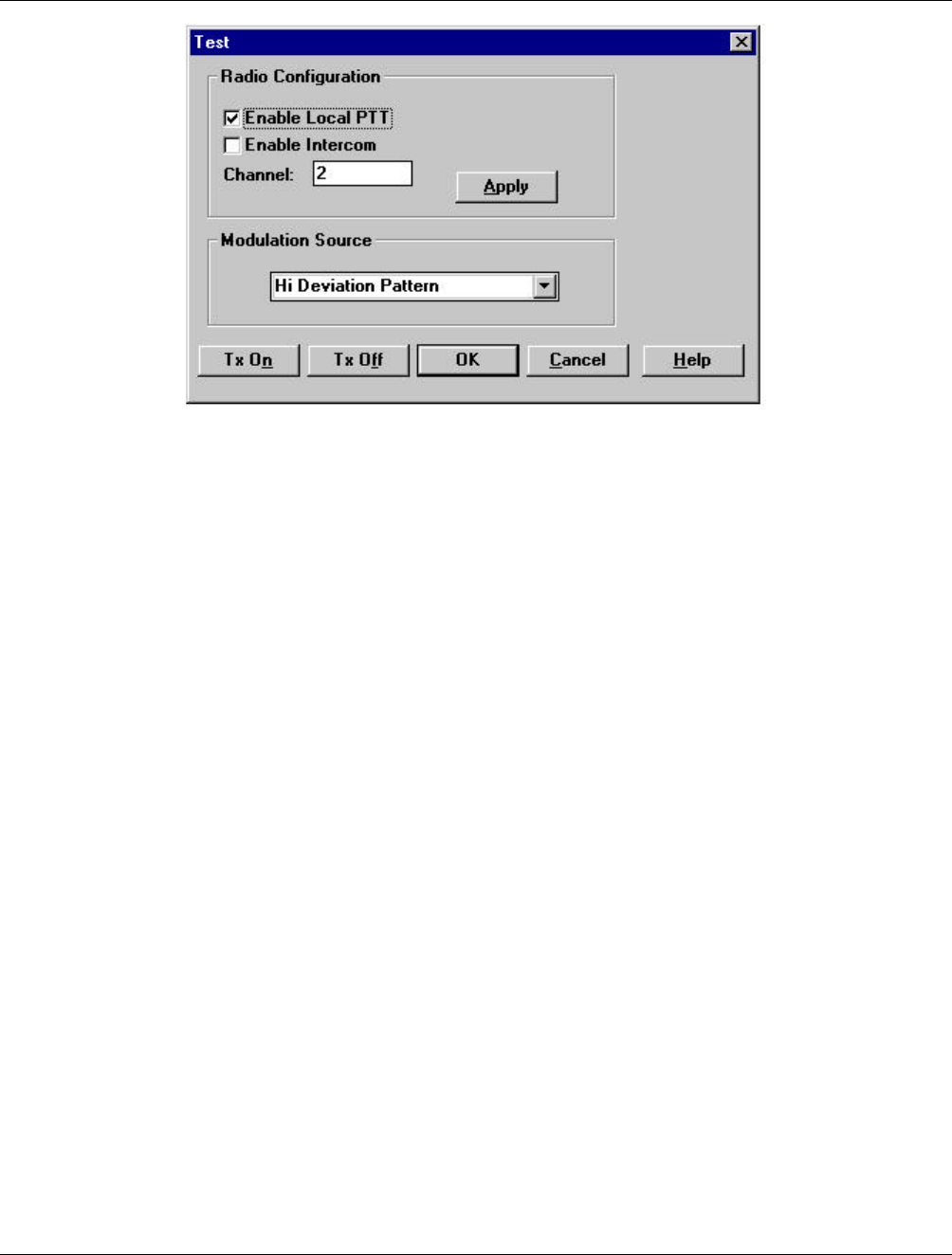
The Test Dialog boxes allows the following radio controls to be exercised:
• Enable Local PTT (on/off) check box allows the user to transmit from a front panel microphone while
the TDM is connected even if the channel in use has front panel PTT turned off.
• Enable Intercom check box shall allow the user to use a front panel microphone or handset to talk to a
tone remote or console operator via 4 W/2 W interface while the TDM is connected.
• Select Channel.
The Test Radio dialog box will appear as shown in Figure 6-7.
Installation and Operator Handbook DRB-25 Diagnostics Monitor
AMX-MA-00656 Issue 0.02 (USA) 11
Figure 6-7 Test Radio Dialog Box
Apply
The Apply button sets the Enable Local PTT, Enable Intercom and Channel. This is, however, not stored on
the Transceiver Module.
Tx On
The TDM Test dialog box Tx On button selection causes the TDM to write the factory test parameter to the
selected Transceiver Module. The transmitter is turned on using the selected test tone as the modulation
source. Note that if TDM is closed with TX On still selected then TDM will turn the transmitter off before
closing and the transceiver will revert to its normal operating mode for its current channel.
Tx Off
Turns the transmitter off.
OK
Closes the Test dialog box returns the user to the Main dialog box. The transmitter is returned to the off
state and the Enable Local PTT and Enable Intercom revert to their previous settings.
If a channel has been changed during a test session then a box will appear after the user closes the test dialog
box : ‘The current channel of Radio x has been changed during this session. Do you wish to change the radio
back to its original channel?’ Yes/No. If yes is clicked, then the channel will be changed back to the channel
in use when the TDM session was started.
Cancel
Closes the Test dialog box without writing data to the .INI file..
Help
Provides access to on-line help on the Polling Interval dialog box.
Installation and Operator Handbook DRB-25 Diagnostics Monitor
AMX-MA-00656 Issue 0.02 (USA) 12
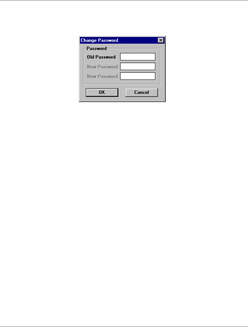
6.3.7 Changing the Password
To change the password, from the main menu activate the Status/Test pull-down menu and select Change
Passwords. The Change Password dialog box will appear as shown in figure 6-8.
Figure 6-8 Change Password Dialog Box
Enter the old password, followed by the desired new one. Enter the new password again in the bottom field
for verification and click OK. The Tab key may be used to move between the text boxes.