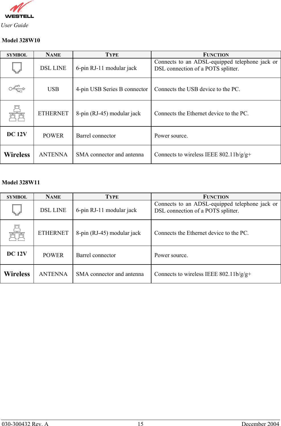
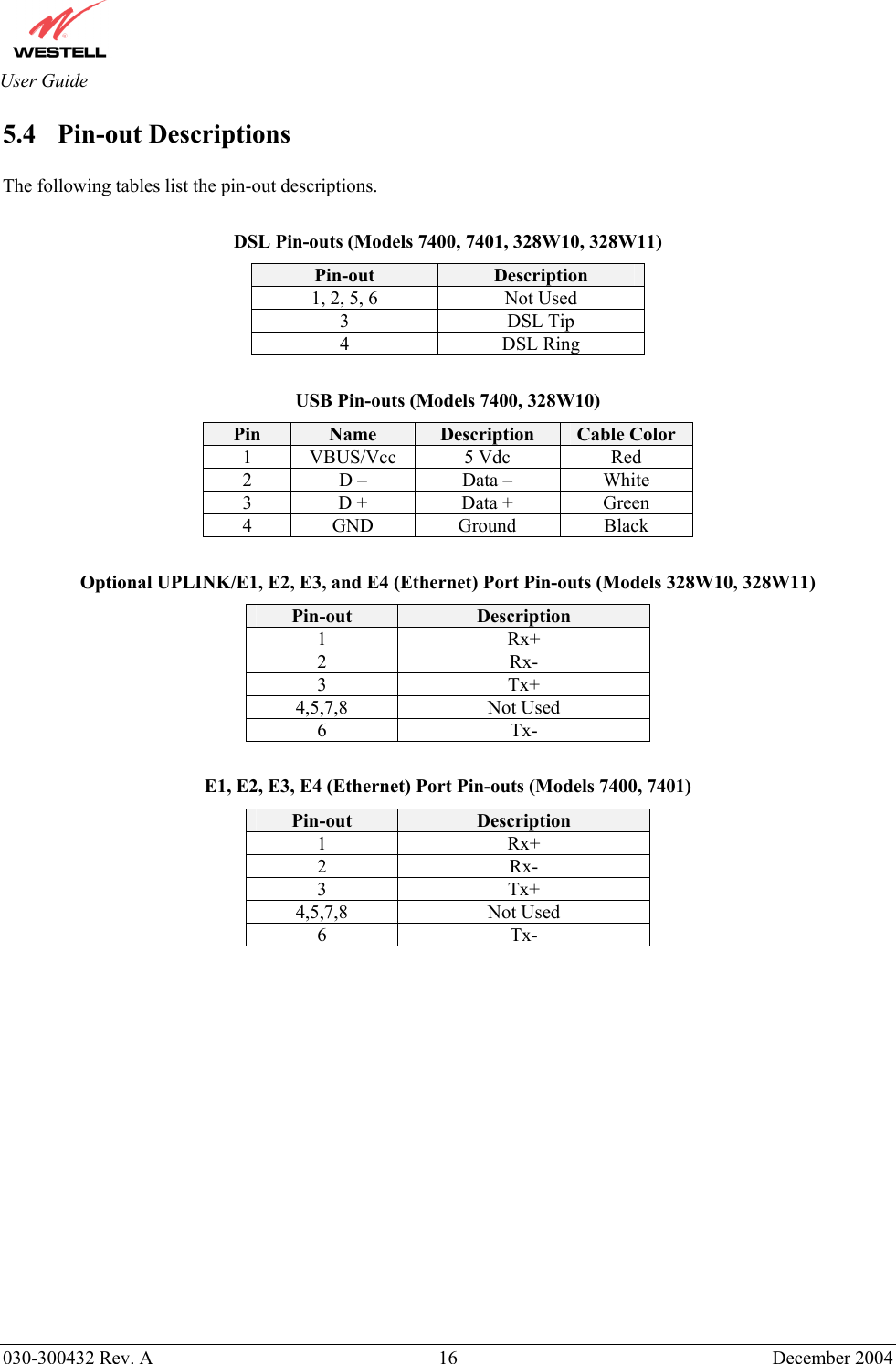
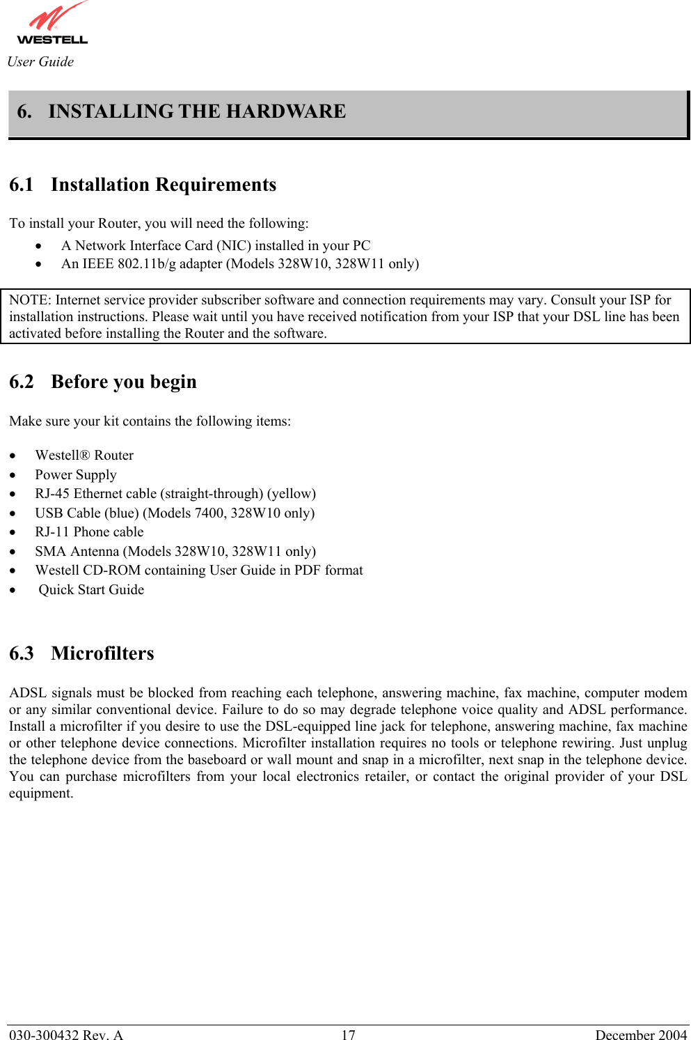
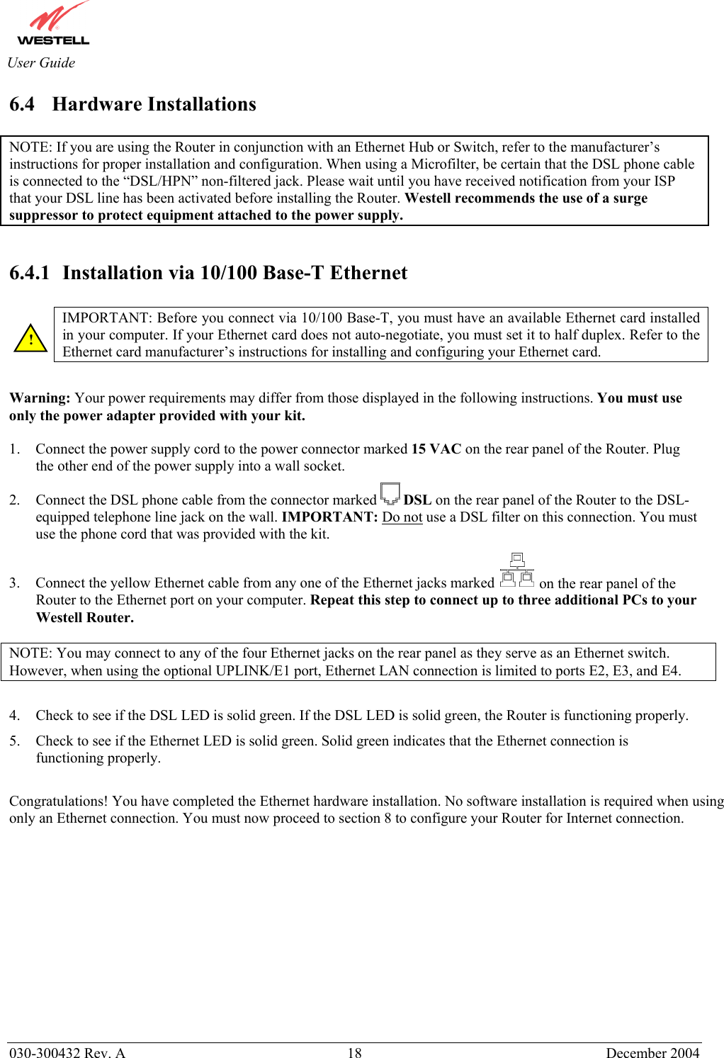
Westell A90328XX-07 Spread Spectrum Transmitter User Manual PRODUCT DESCRIPTION
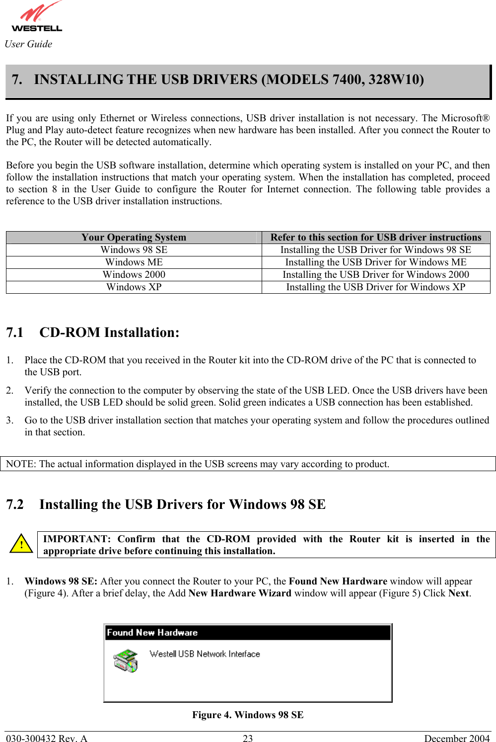
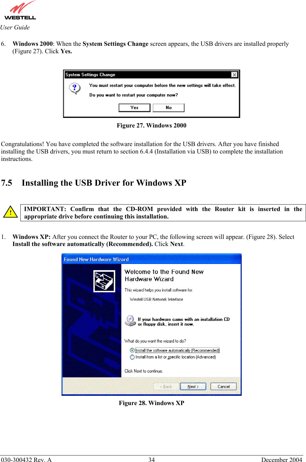
Westell Inc Spread Spectrum Transmitter PRODUCT DESCRIPTION
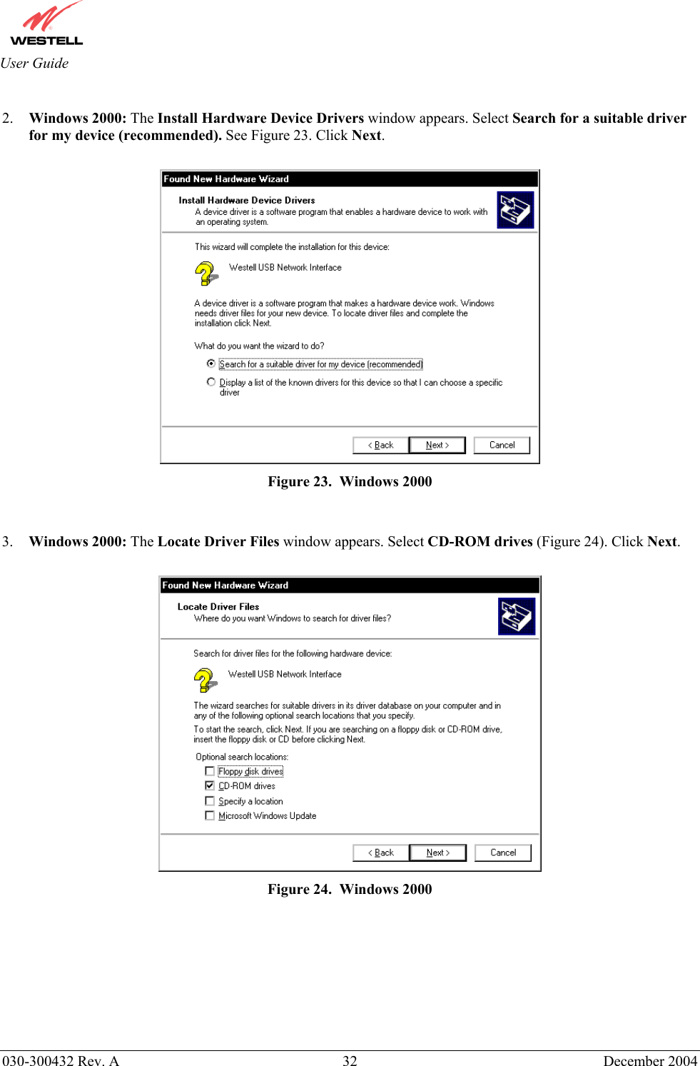
Westell >
Contents
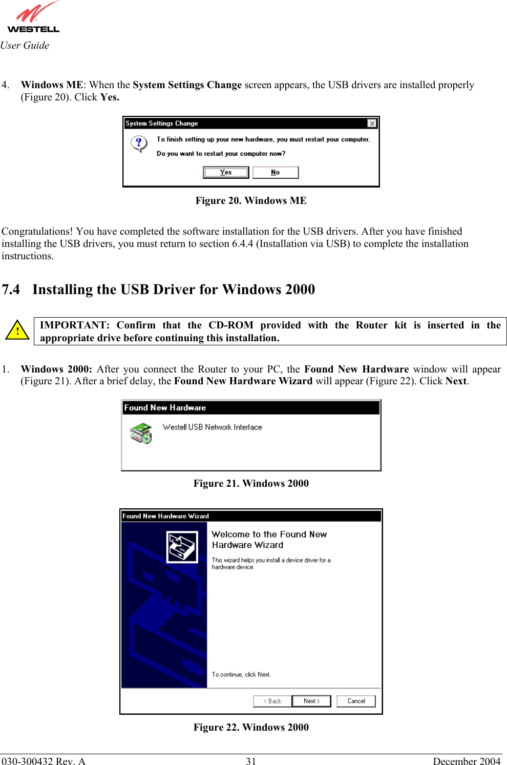
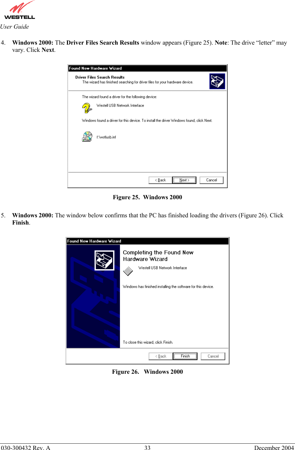
- 1. Users Manual Part1
- 2. Users Manual Part2
- 3. Users Manual Part3
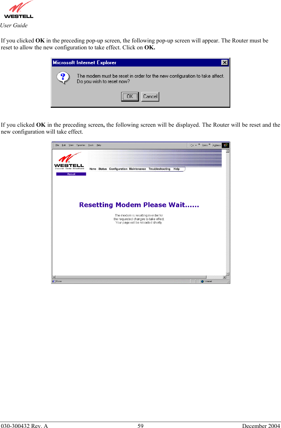
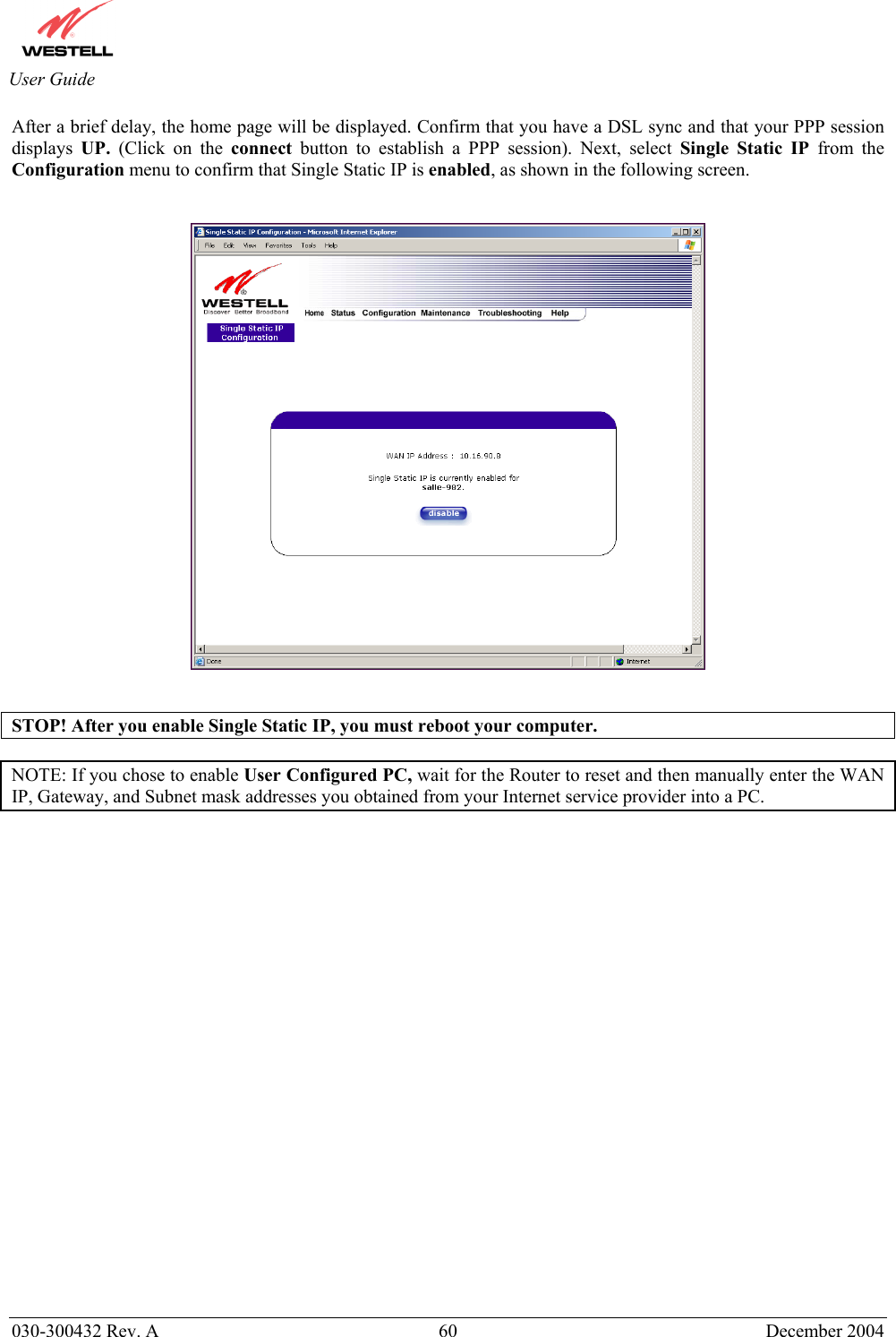
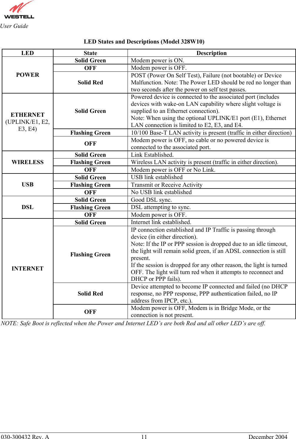
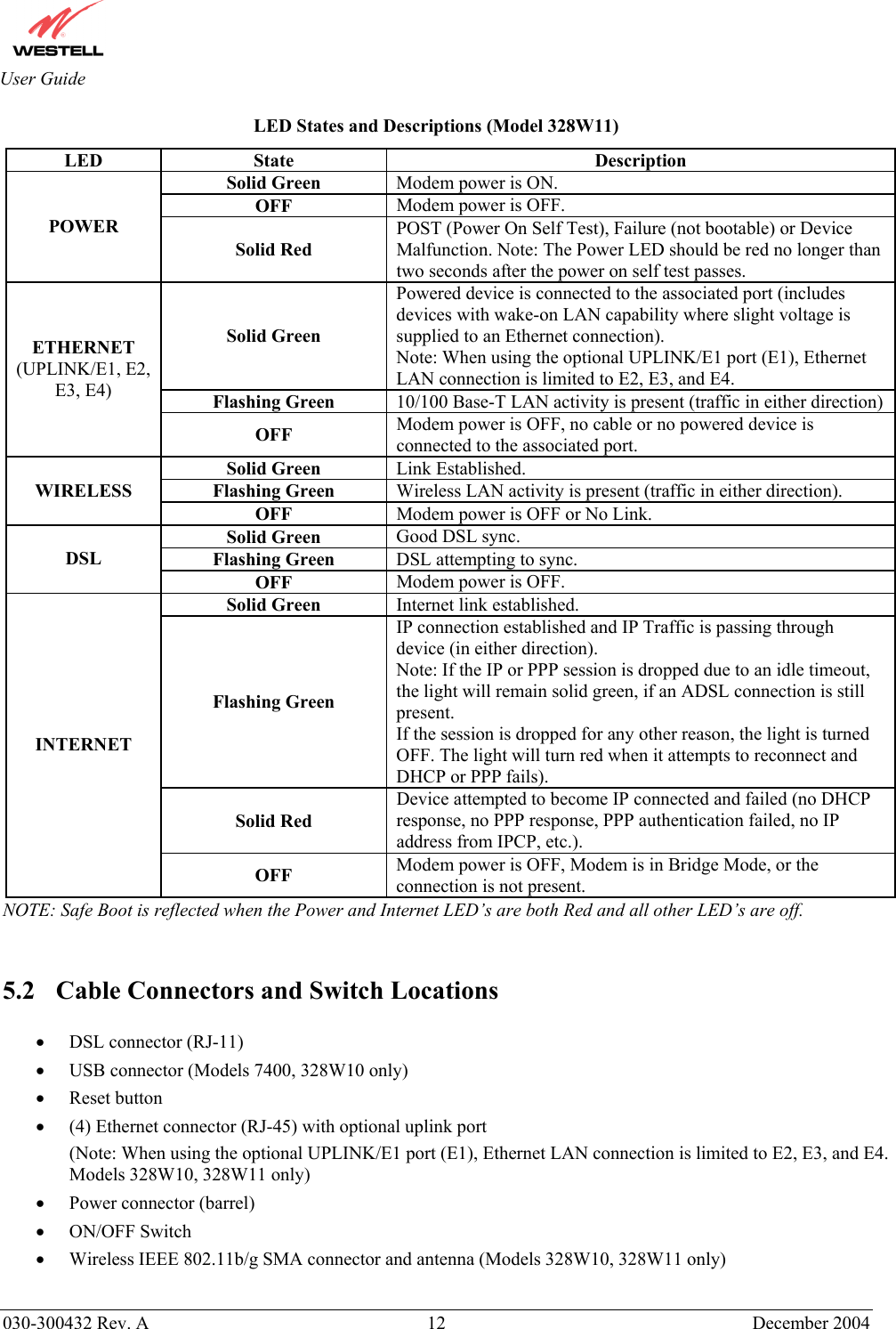
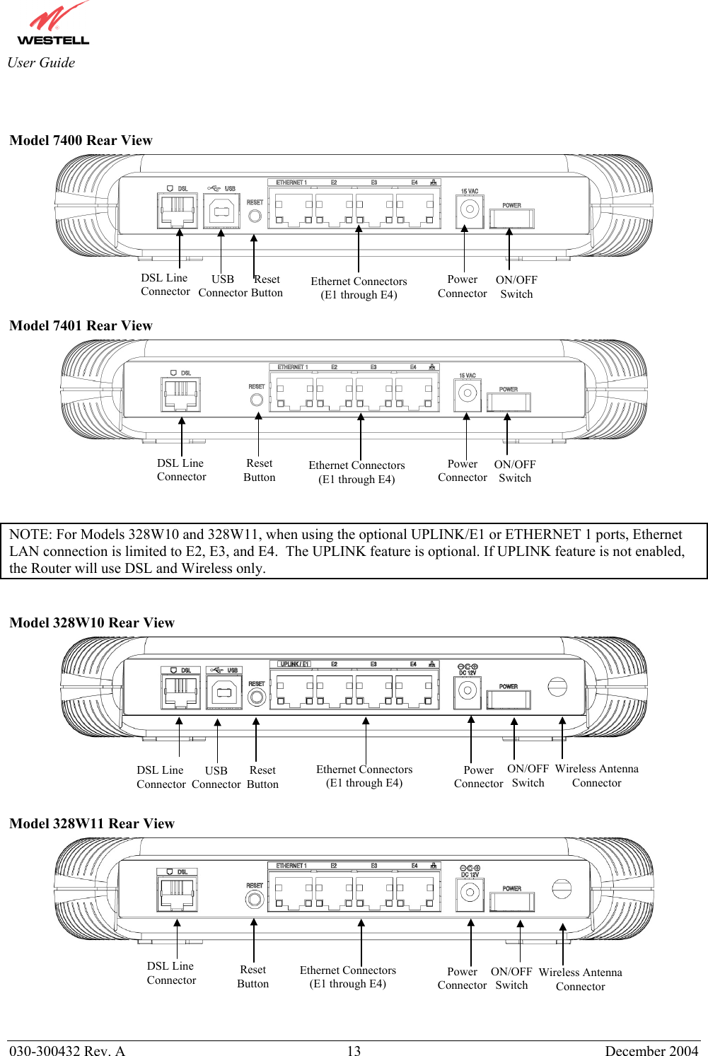
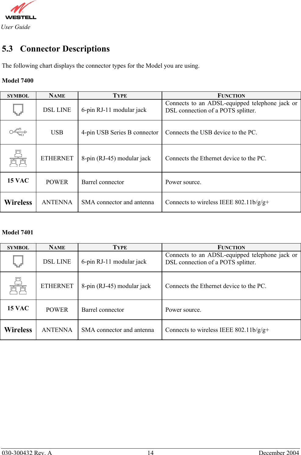
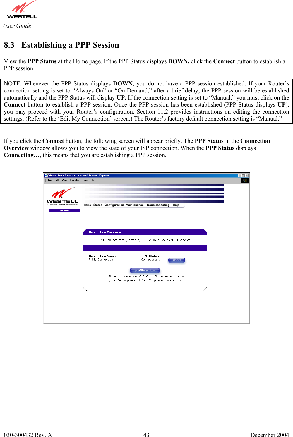
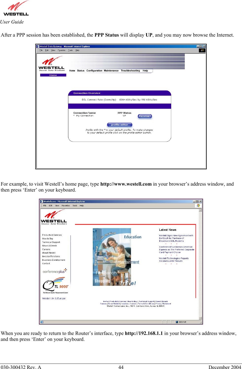
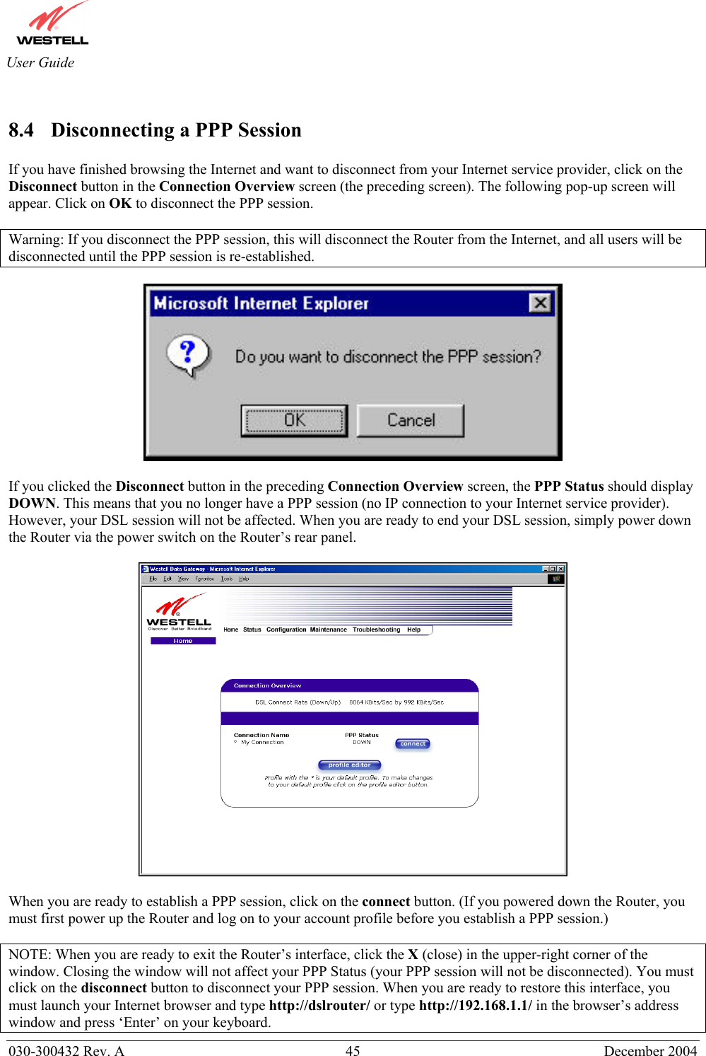
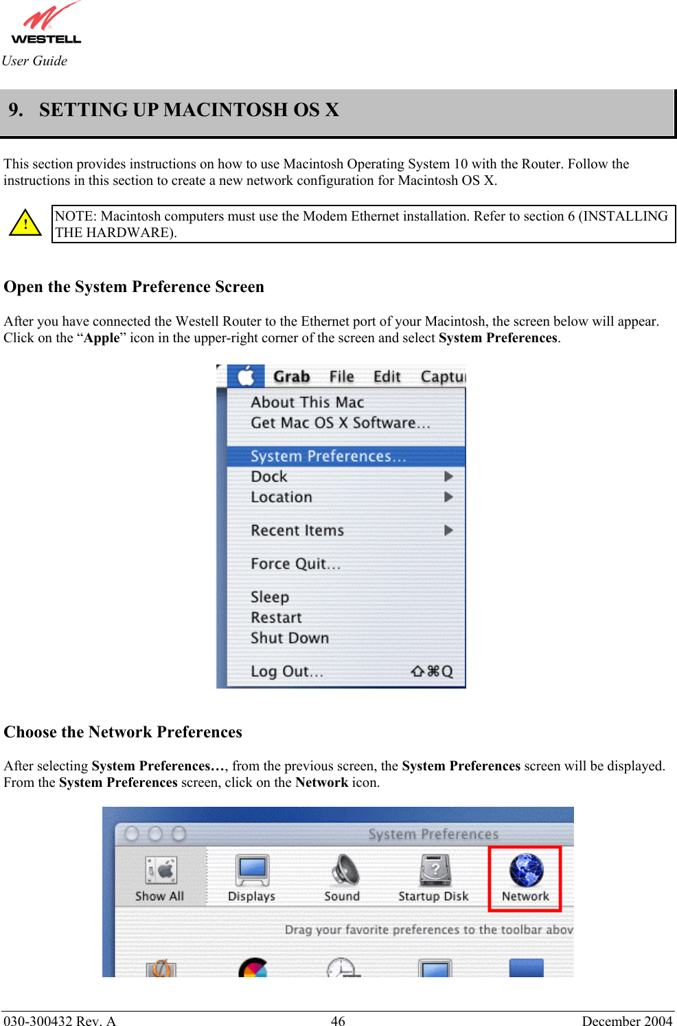
Users Manual Part1
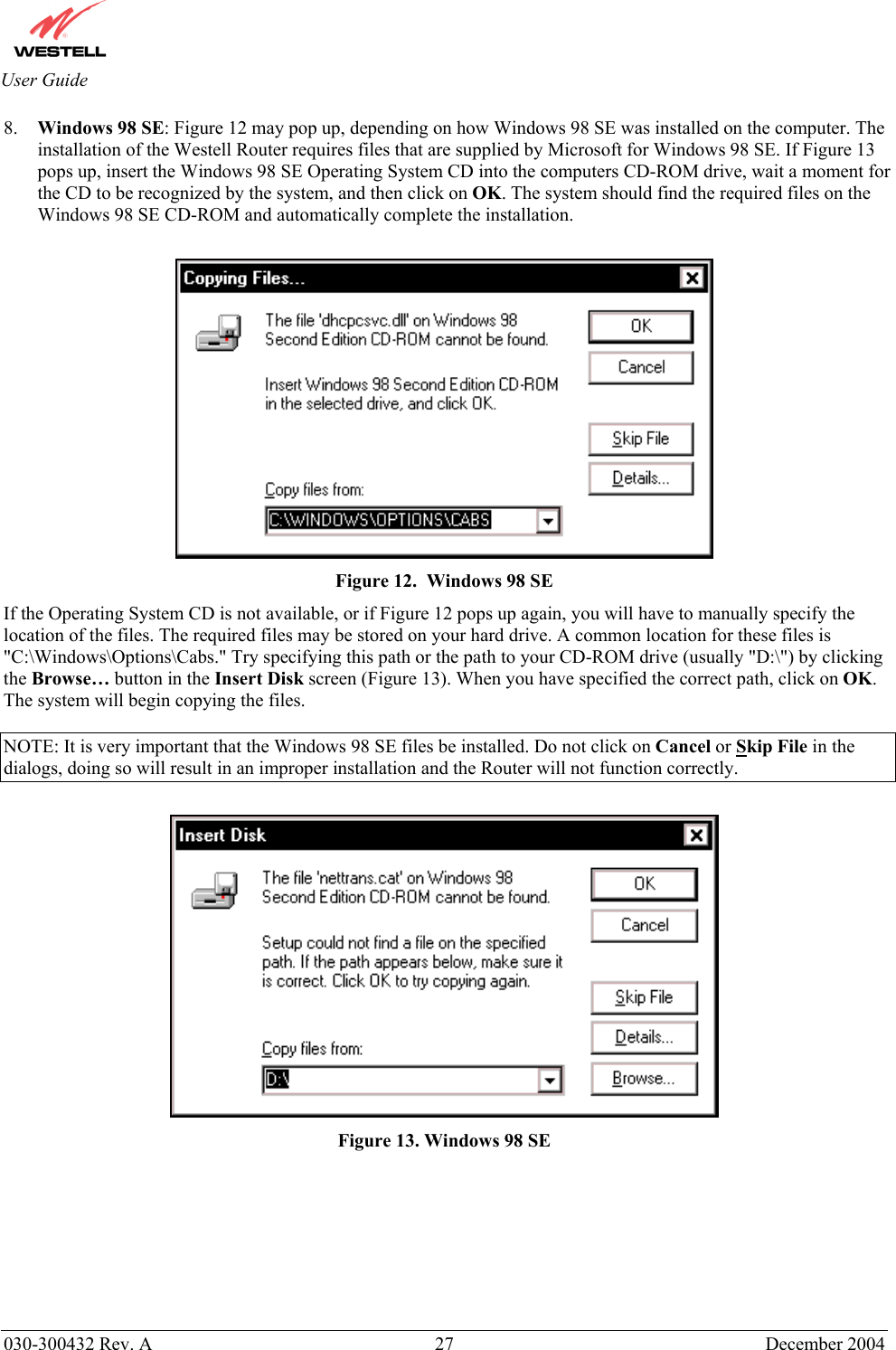
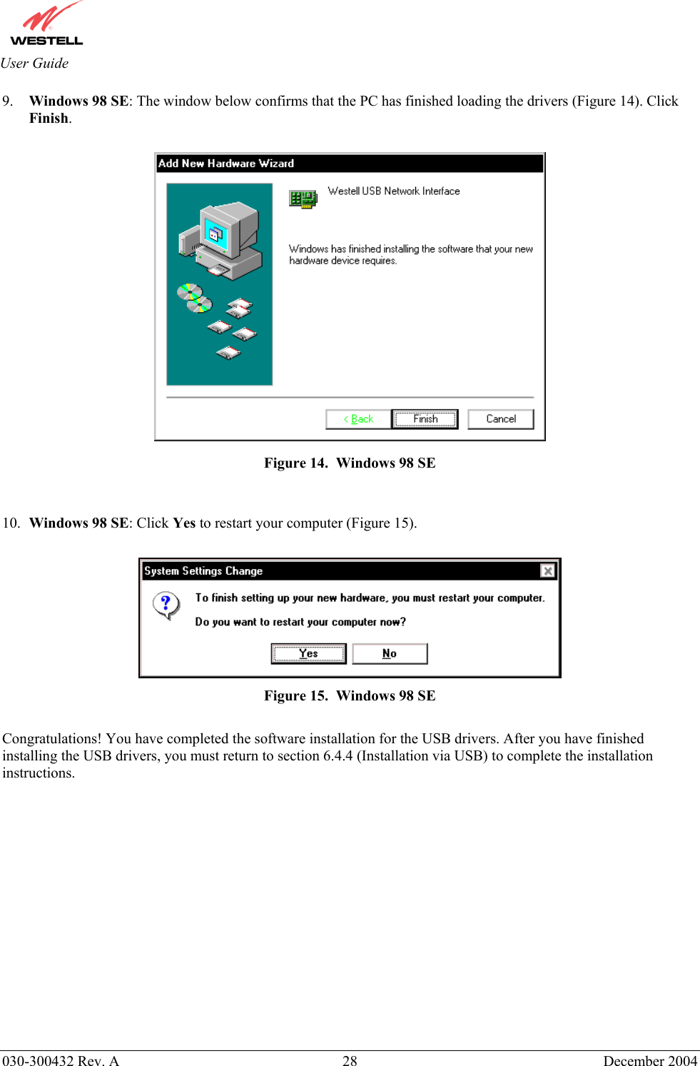
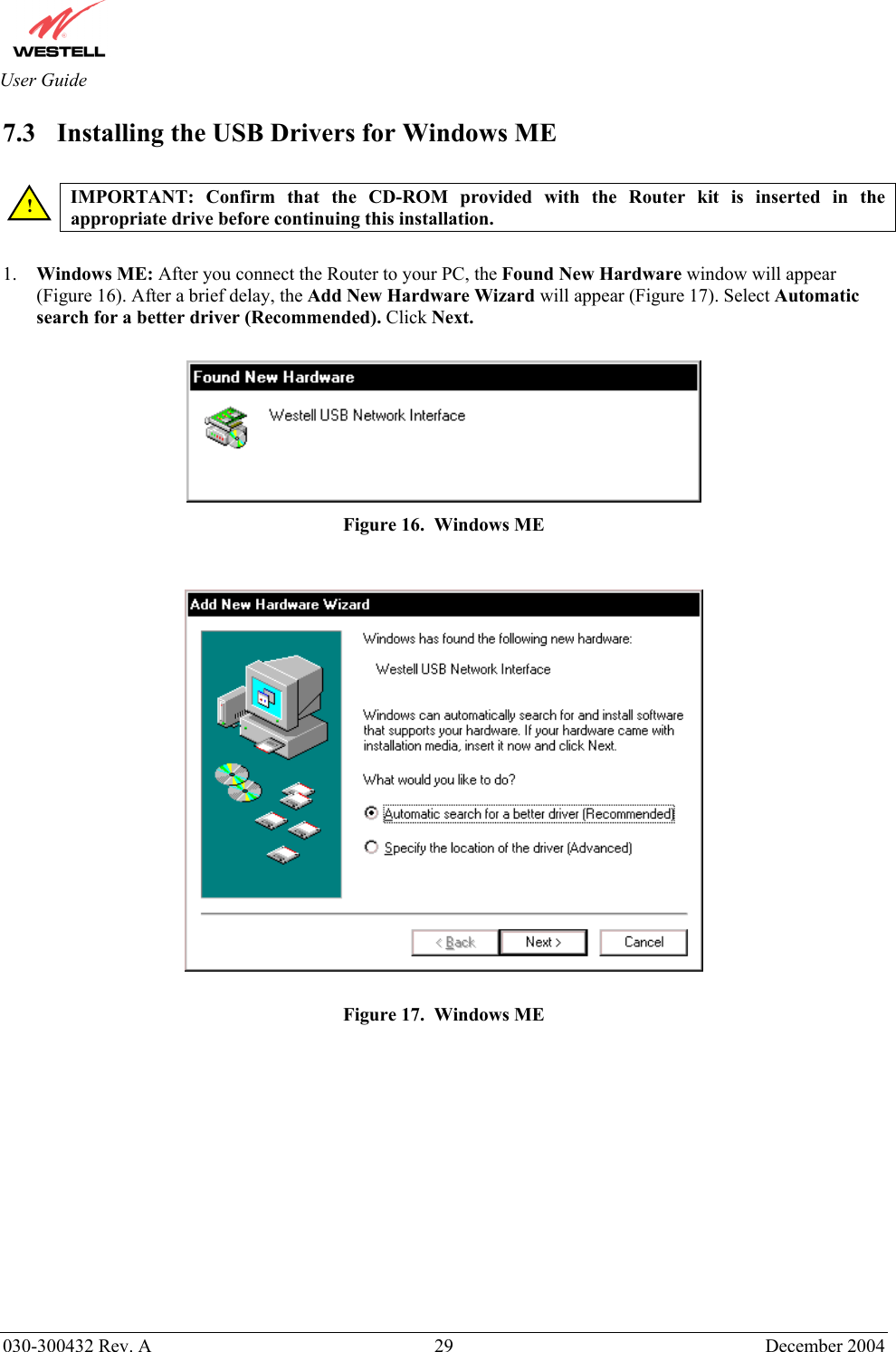
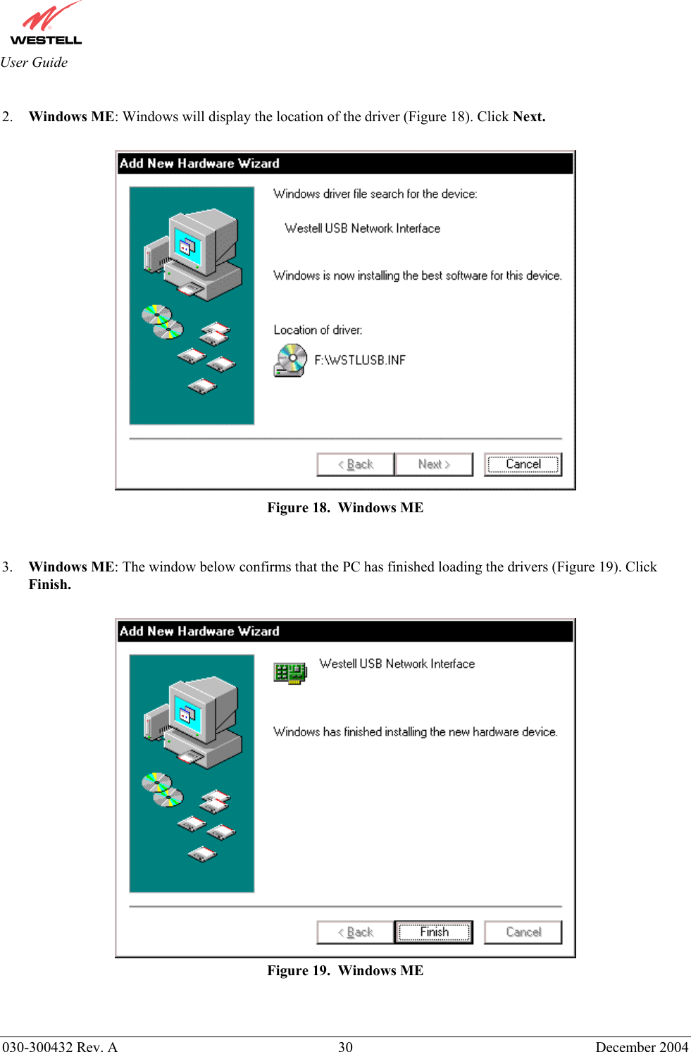
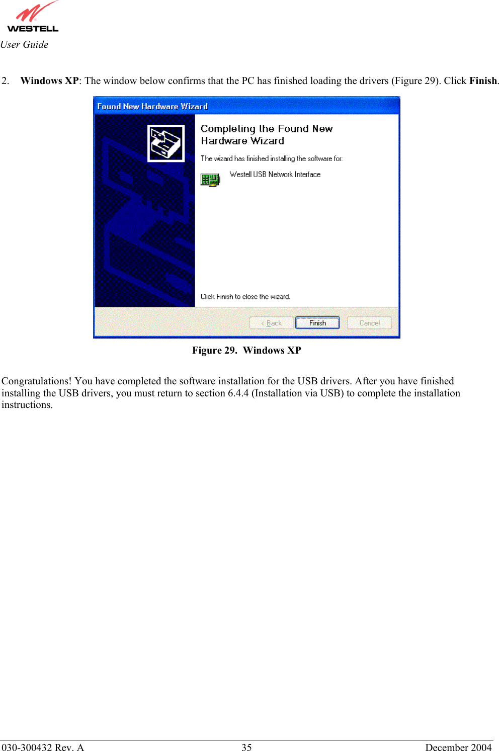
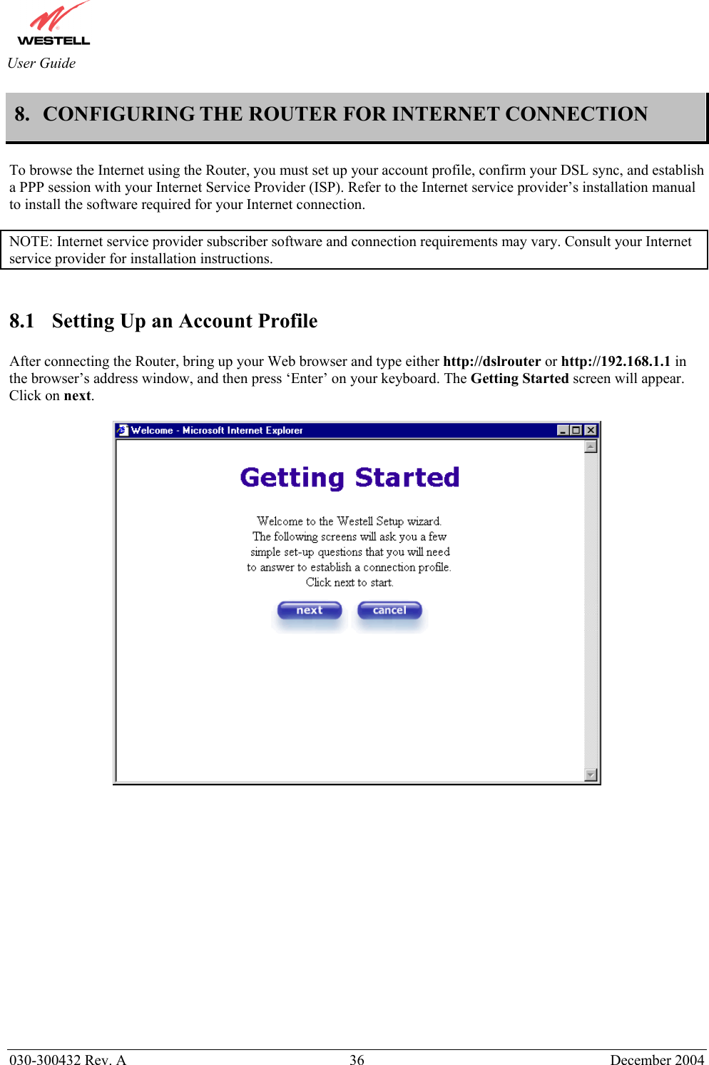
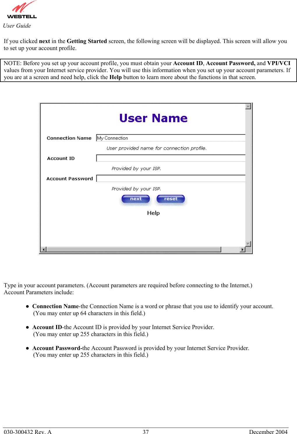
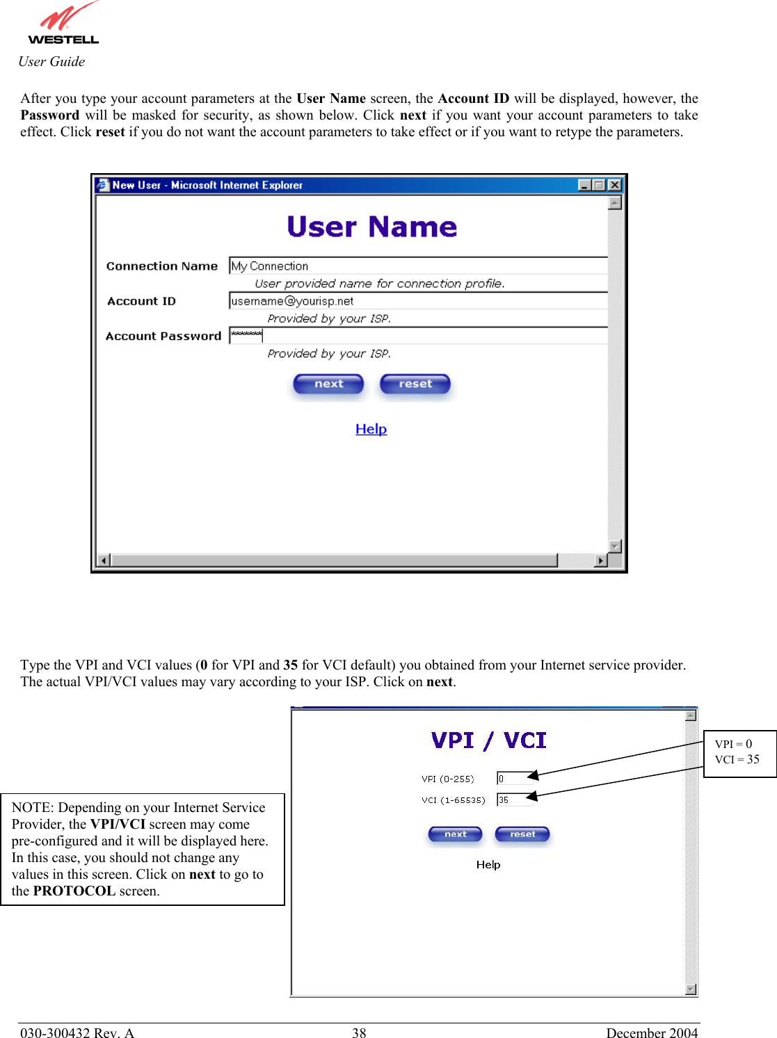
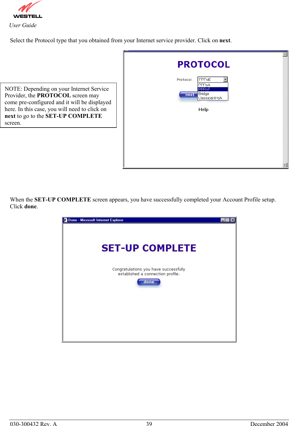
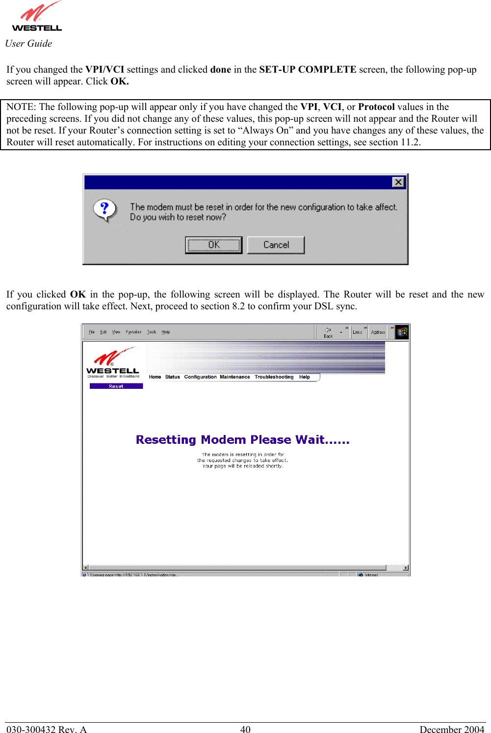
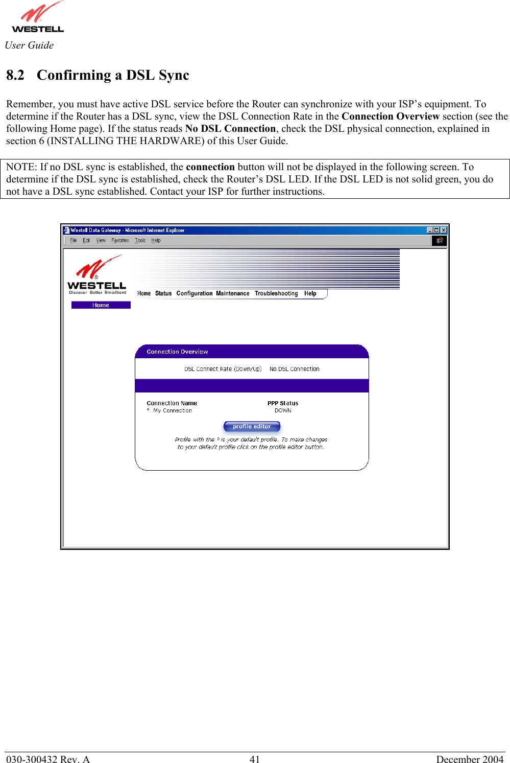
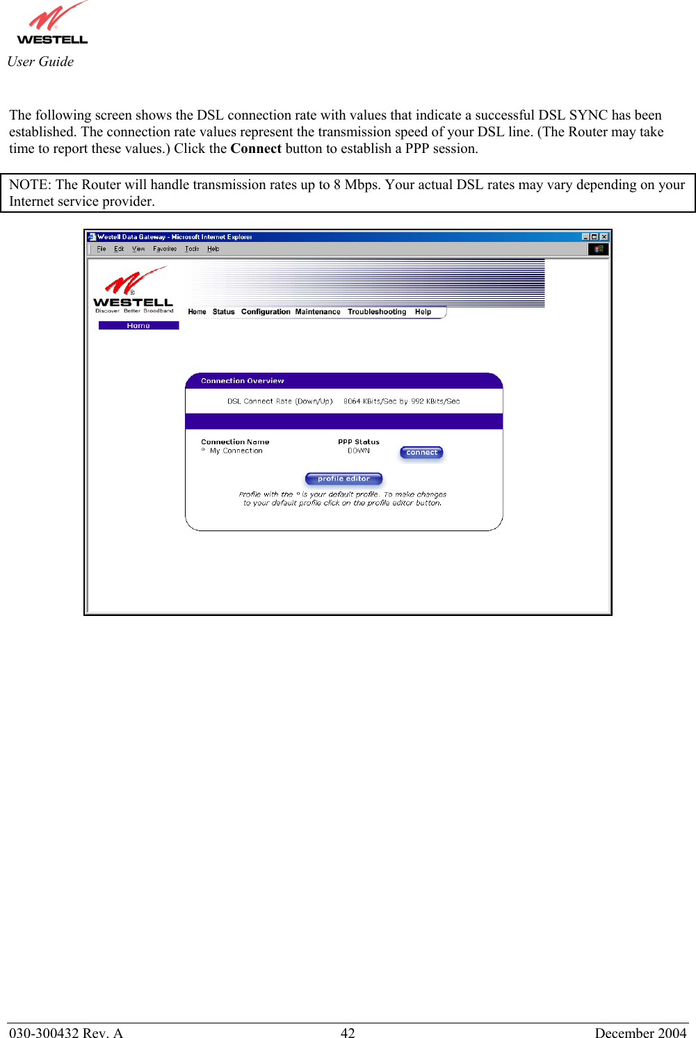
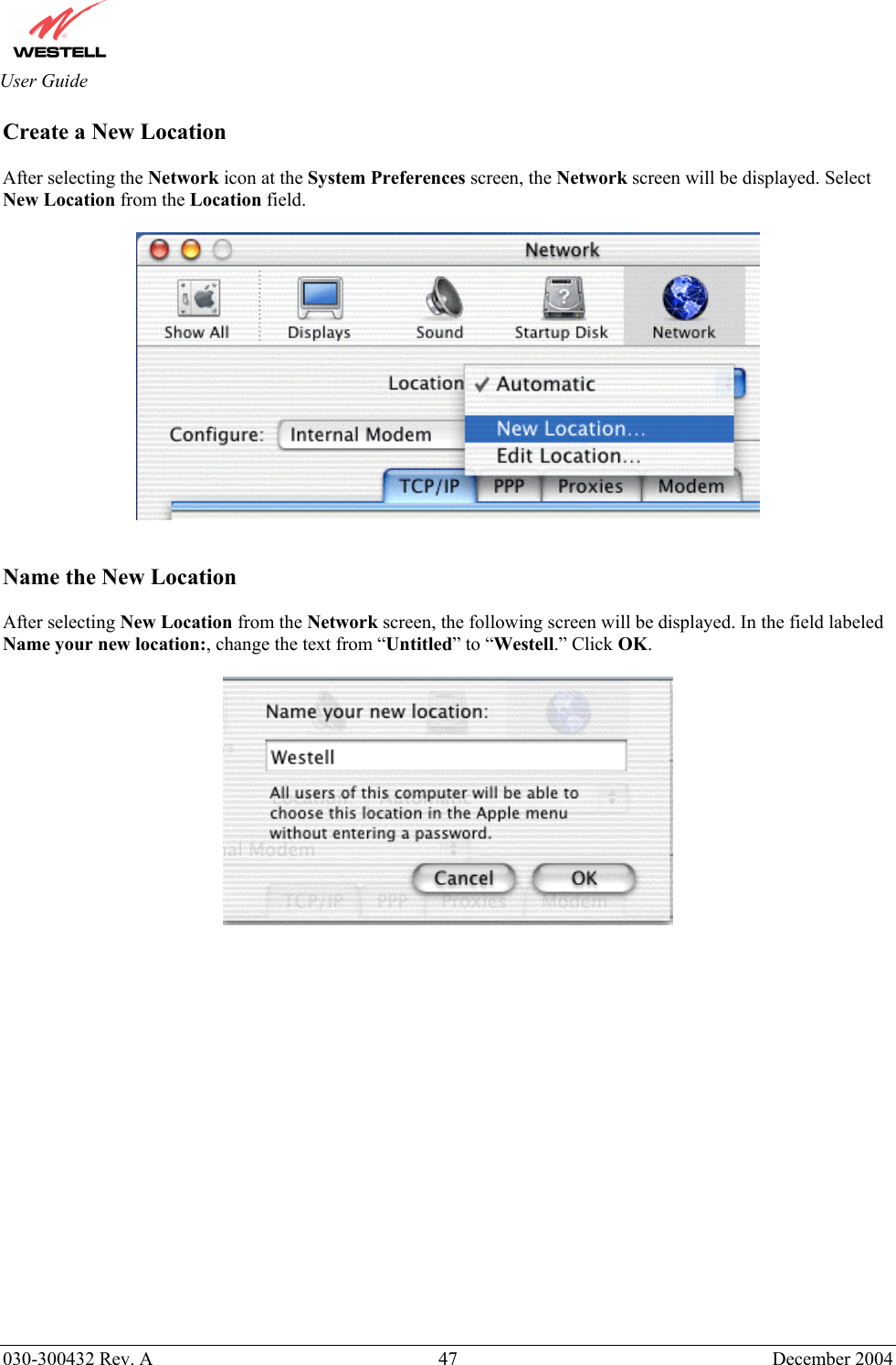
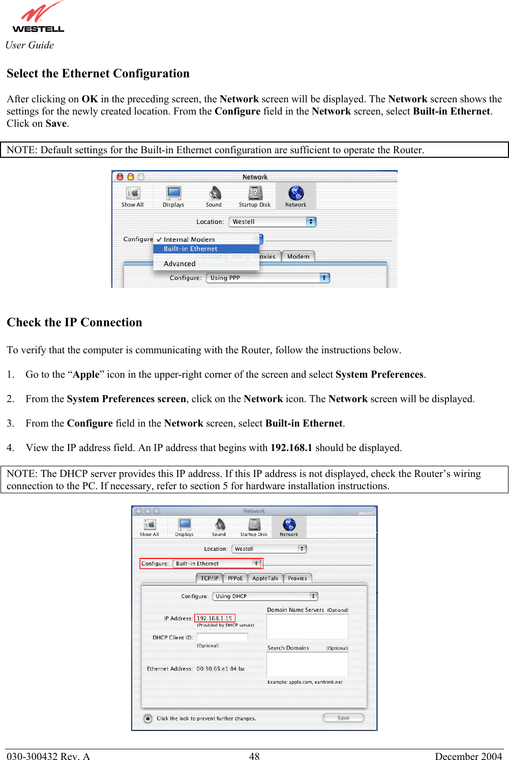
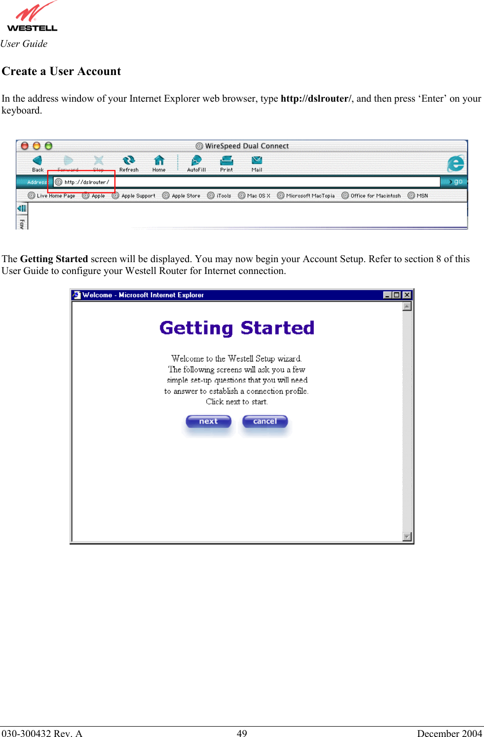
![030-300432 Rev. A 50 December 2004 User Guide The following sections explain the advanced features of your Westell Router. [This Page Intentionally Left Blank]](https://usermanual.wiki/Westell/A90328XX-07.Users-Manual-Part1/User-Guide-528325-Page-50.png)