Westell A90328XX-07 Spread Spectrum Transmitter User Manual PRODUCT DESCRIPTION
Westell Inc Spread Spectrum Transmitter PRODUCT DESCRIPTION
Westell >
Contents
- 1. Users Manual Part1
- 2. Users Manual Part2
- 3. Users Manual Part3
Users Manual Part1

Copyright © 2004 Westell, Inc. 030-300432 Rev. A
ULTRALINE (MODELS 7400/7401)
VERSALINK (MODELS 328W10/328W11)
USER GUIDE

030-300432 Rev. A 2 December 2004
User Guide Westell Router (Models 7400, 7401, 328W10, 328W11)
TABLE OF CONTENTS
1. PRODUCT DESCRIPTION ..................................................................................................................................4
2. SAFETY INSTRUCTIONS ...................................................................................................................................4
3. REGULATORY INFORMATION ........................................................................................................................5
3.1 FCC Compliance Note...............................................................................................................................5
3.2 Canada Certification Notice.......................................................................................................................6
4. NETWORKING REQUIREMENTS .....................................................................................................................8
5. HARDWARE FEATURES....................................................................................................................................9
5.1 LED Indicators...........................................................................................................................................9
5.2 Cable Connectors and Switch Locations .................................................................................................12
5.3 Connector Descriptions............................................................................................................................14
5.4 Pin-out Descriptions ................................................................................................................................16
6. INSTALLING THE HARDWARE......................................................................................................................17
6.1 Installation Requirements ........................................................................................................................17
6.2 Before you begin......................................................................................................................................17
6.3 Microfilters ..............................................................................................................................................17
6.4 Hardware Installations .............................................................................................................................18
7. INSTALLING THE USB DRIVERS (Models 7400, 328W10)...........................................................................23
7.1 CD-ROM Installation: .............................................................................................................................23
7.2 Installing the USB Drivers for Windows 98 SE ......................................................................................23
7.3 Installing the USB Drivers for Windows ME..........................................................................................29
7.4 Installing the USB Driver for Windows 2000 .........................................................................................31
7.5 Installing the USB Driver for Windows XP ............................................................................................34
8. CONFIGURING THE ROUTER FOR INTERNET CONNECTION .................................................................36
8.1 Setting Up an Account Profile .................................................................................................................36
8.2 Confirming a DSL Sync ..........................................................................................................................41
8.3 Establishing a PPP Session ......................................................................................................................43
8.4 Disconnecting a PPP Session...................................................................................................................45
9. SETTING UP Macintosh OS X............................................................................................................................46
10. SETTING UP ADVANCED CONFIGURATION ..............................................................................................51
11. HOME ..................................................................................................................................................................52
11.1 Adding Account Profiles .........................................................................................................................53
11.2 Editing Account Profiles..........................................................................................................................54
12. STATUS...............................................................................................................................................................55
12.1 Connection Summary ..............................................................................................................................55
12.2 About .......................................................................................................................................................56

030-300432 Rev. A 3 December 2004
User Guide Westell Router (Models 7400, 7401, 328W10, 328W11)
13. CONFIGURATION .............................................................................................................................................57
13.1 Single Static IP – Single IP Address PassThrough ..................................................................................57
13.2 Service Configuration..............................................................................................................................63
13.3 Firewall Configuration.............................................................................................................................74
13.4 Wireless Configuration (Models 328W10, 328W11) ..............................................................................78
13.5 Advanced LAN........................................................................................................................................85
13.6 Advanced WAN.....................................................................................................................................101
14. SETTING UP ADVANCED SERVICE CONFIGURATION...........................................................................135
14.1 Port Forwarding Ranges of Ports...........................................................................................................136
14.2 Adding Port Forwarding Ports...............................................................................................................136
14.3 Port Forwarding Trigger Ports...............................................................................................................137
14.4 Adding Local Trigger Ports ...................................................................................................................138
14.5 Static NAT.............................................................................................................................................139
14.6 Enabling Static NAT..............................................................................................................................140
14.7 Disabling Static NAT.............................................................................................................................141
15. MAINTENANCE...............................................................................................................................................143
15.1 Backup/Restore......................................................................................................................................143
15.2 Firewall Log ..........................................................................................................................................144
15.3 Administrative Password .......................................................................................................................146
15.4 Remote Access.......................................................................................................................................147
15.5 Update Device .......................................................................................................................................148
16. TROUBLESHOOTING .....................................................................................................................................154
16.1 System Self Tests...................................................................................................................................154
16.2 Diagnostic Logs.....................................................................................................................................156
16.3 Statistics.................................................................................................................................................159
16.4 Status .....................................................................................................................................................164
17. NAT SERVICES................................................................................................................................................170
18. TECHNICAL SUPPORT INFORMATION ......................................................................................................174
19. WARRANTY AND REPAIRS..........................................................................................................................174
20. SOFTWARE LICENSE AGREEMENT............................................................................................................175
21. PUBLICATION INFORMATION.....................................................................................................................177
030-300432 Rev. A 4 December 2004
User Guide Westell Router (Models 7400, 7401, 328W10, 328W11)
1. PRODUCT DESCRIPTION
Your Westell® Router provides reliable, high-speed, Internet access to your existing small office phone line. Your
ADSL connection is “always-on” ending the hassles of dial-up modems and busy signals. Installation is easy ... no
tools ... no headaches. Simply connect the hardware, apply power, and perform the simple software configuration for
Router and you are on the Internet.
The Westell® Router is capable of data rates hundreds of times faster than a traditional analog modem. But unlike
analog modems, your Westell® Router allows you to use the same phone line for simultaneous voice/fax
communications and high-speed Internet access, eliminating the need for dedicated phone lines for voice and data
needs. The Router supports a variety of networking interfaces such as wireless 802.11b/g/g+, ADSL, Ethernet and
the following optional features:
NOTE: The actual features and functions of your product may vary depending on the model you are using.
2. SAFETY INSTRUCTIONS
Never install any telephone wiring during a lightning storm.
Never install telephone jacks in wet locations unless the jack is specifically designed for wet locations.
Never touch non-insulated telephone wires or terminals unless the telephone line has been disconnected at the
network interface.
Use caution when installing or modifying telephone lines.
WARNING
Risk of electric shock. Voltages up to 140 Vdc (with reference to
ground) may be present on telecommunications circuits.

030-300432 Rev. A 5 December 2004
User Guide Westell Router (Models 7400, 7401, 328W10, 328W11)
3. REGULATORY INFORMATION
3.1 FCC Compliance Note
(FCC ID: CH8-328WXX-6)
This equipment has been tested and found to comply with the limits for a Class B digital device, pursuant to Part 15
of the Federal Communication Commission (FCC) Rules. These limits are designed to provide reasonable protection
against harmful interference in a residential installation. This equipment generates, uses, and can radiate radio
frequency energy, and if not installed and used in accordance with the instructions, may cause harmful interference
to radio communications. However, there is no guarantee that interference will not occur in a particular installation.
If this equipment does cause harmful interference to radio or television reception, which can be determined by
turning the equipment OFF and ON, the user is encouraged to try to correct the interference by one or more of the
following measures:
• Reorient or relocate the receiving antenna.
• Increase the separation between the equipment and the receiver.
• Connect the equipment to a different circuit from that to which the receiver is connected.
• Consult the dealer or an experienced radio/TV technician for help.
Modifications made to the product, unless expressly approved by Westell Inc., could void the users’ right to
operate the equipment.
RF EXPOSURE
This device has been tested and complies with FCC RF Exposure (SAR) limits in typical laptop computer
configurations and this device can be used in desktop or laptop computers with side-mounted PCMCIA slots,
which can provide 1 cm separation distance from the antenna to the body of the user or a nearby person.
Thin laptop computers may need special attention to maintain antenna spacing while operating. This device
cannot be used with handheld PDAs (personal digital assistants). Use in other configurations may not ensure
compliance with FCC RF exposure guidelines. This device and its antenna must not be co-located or operate
in conjunction with another antenna or transmitter.
PART 68 – COMPLIANCE REGISTRATION
This equipment (Models 7400, 7401, 328W10, 328W11) complies with Part 68 of the FCC rules and the
requirements adopted by the ACTA. A label on the bottom of this equipment contains, among other information, the
Ringer Equivalence Number (REN) and the product identifier. For products approved after July 23, 2001 the
product identifier is in the format US:AAAEQ##TXXXX. The digits represented by ## are the REN without a
decimal point (e.g. 03 is a REN of 0.3). The REN is used to determine the number of devices that may be connected
to a telephone line. For earlier products, the REN is separately shown on the label. If requested, this number must be
provided to the telephone company.
Excessive RENs on a telephone line may result in the devices not ringing in response to an incoming call. In most,
but not all areas, the sum of RENs should not exceed five (5.0). To be certain of the number of devices that may be
connected to a line, as determined by the total RENs, contact the local telephone company.
This equipment is designated to connect to the telephone network or premises wiring using a compatible modular
jack that is Part 68 compliant. An FCC compliant telephone cord and modular plug is provided with the equipment.
See the Installation Information section of this User Guide for details.

030-300432 Rev. A 6 December 2004
User Guide Westell Router (Models 7400, 7401, 328W10, 328W11)
A plug and jack used to connect this equipment to the premises wiring and telephone network must comply with the
applicable FCC Part 68 rules and requirements adopted by the ACTA. A compliant telephone cord and modular plug
is provided with this product. It is designed to be connected to a compatible modular jack that is also compliant. See
installation instruction for details.
If this terminal equipment (Models 7400, 7401, 328W10, 328W11) causes harm to the telephone network, the
telephone company may request you to disconnect the equipment until the problem is resolved. The telephone
company will notify you in advance if temporary discontinuance of service is required. If advance notification is not
practical, the telephone company will notify you as soon as possible. You will be advised of your right to file a
complaint with the FCC if you believe such action is necessary.
If you experience trouble with this equipment (Models 7400, 7401, 328W10, 328W11), do not try to repair the
equipment yourself. The equipment cannot be repaired in the field. Contact your ISP, or contact the original
provider of your DSL equipment.
The telephone company may make changes to their facilities, equipment, operations, or procedures that could affect
the operation of this equipment. If this happens, the telephone company will provide advance notice in order for you
to make the modifications necessary to maintain uninterrupted service.
If your home has specially wired alarm equipment connected to the telephone line, ensure that the installation of this
equipment (Models 7400, 7401, 328W10, 328W11) does not disable your alarm equipment. If you have questions
about what will disable alarm equipment, consult your telephone company or a qualified installer.
This equipment cannot be used on public coin phone service provided by the telephone company. Connection of this
equipment to party line service is subject to state tariffs.
3.2 Canada Certification Notice
The Industry Canada label identifies certified equipment. This certification means that the equipment meets certain
telecommunications network protective, operations and safety requirements as prescribed in the appropriate
Terminal Equipment Technical Requirements document(s). The department does not guarantee the equipment will
operate to the user’s satisfaction.
This equipment meets the applicable Industry Canada Terminal Equipment Technical Specification. This is
confirmed by the registration number. The abbreviation, IC, before the registration number signifies that registration
was performed based on a Declaration of Conformity indicating that Industry Canada technical specification were
met. It does not imply that Industry Canada approved the equipment. The Ringer Equivalence Number (REN) is 0.0.
The Ringer Equivalence Number that is assigned to each piece of terminal equipment provides an indication of the
maximum number of terminals allowed to be connected to a telephone interface. The termination on an interface
may consist of any combination of devices subject only to the requirement that the sum of the Ringer Equivalence
Numbers of all the devices does not exceed five.
Before installing this equipment, users should ensure that it is permissible to be connected to the facilities of the
local Telecommunication Company. The equipment must also be installed using an acceptable method of
connection. The customer should be aware that compliance with the above conditions may not prevent degradation
of service in some situations. Connection to a party line service is subject to state tariffs. Contact the state public
utility commission, public service commission, or corporation commission for information.
If your home has specially wired alarm equipment connected to the telephone line, ensure that the installation of this
equipment (Models 7400, 7401, 328W10, 328W11) does not disable your alarm equipment. If you have questions
about what will disable alarm equipment, consult your telephone company or a qualified installer.
If you experience trouble with this equipment (Models 7400, 7401, 328W10, 328W11), do not try to repair the
equipment yourself. The equipment cannot be repaired in the field and must be returned to the manufacturer. Repairs

030-300432 Rev. A 7 December 2004
User Guide Westell Router (Models 7400, 7401, 328W10, 328W11)
to certified equipment should be coordinated by a representative, and designated by the supplier. Refer to section 19
in this User Guide for further details.
The termination on an interface may consist of any combination of devices subject only to the requirement that the
sum of the Ringer Equivalence Numbers of all the devices does not exceed five.
Users should ensure, for their own protection, that the electrical ground connections of the power utility, telephone
lines, and internal, metallic water pipe system, if present, are connected together. This precaution may be
particularly important in rural areas.
CAUTION
Users should not attempt to make such connections themselves, but should contact the
appropriate electrical inspection authority, or electrician, as appropriate.

030-300432 Rev. A 8 December 2004
User Guide Westell Router (Models 7400, 7401, 328W10, 328W11)
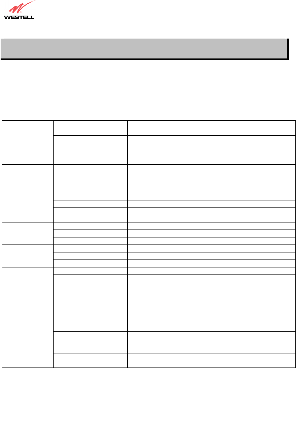
4. NETWORKING REQUIREMENTS
The following system specifications are required for optimum performance of the Router via 10/100 Base-T
Ethernet, Wireless, or USB installations.
CONNECTION
TYPE MINIMUM SYSTEM REQUIREMENTS NETWORKING
SCHEME
ETHERNET
(All Models)
• Pentium® or equivalent class machines
• Microsoft® Windows® (98 SE, ME, 2000, NT 4.0,
or XP) Macintosh® OS X, or Linux installed
• 64 MB RAM (128 MB recommended)
• 10 MB of free hard drive space
• TCP/IP Protocol stack installed
• 10/100 Base-T Network Interface Card (NIC)
• Computer Operating System CD-ROM on hand
Networking via 10/100
Base-T Ethernet
requires an available
Ethernet port with a
10/100 Base-T Network
Interface Card (NIC)
installed.
WIRELESS
IEEE 802.11g
(Models 328W10,
328W11)
• Pentium® or equivalent class machines
• Microsoft® Windows® (98 SE, ME, 2000, or XP) or
Macintosh® OS X installed
• Computer Operating System CD-ROM on hand
• Internet Explorer 4.x or Netscape Navigator 4.x or
higher
• 64 MB RAM (128 MB recommended)
• 10 MB of free hard drive space
• An available IEEE 802.11b/g/g+ PC adapter
Networking via
Wireless or other
802.11b/g/g+ capable
network adapter card.
USB
(Models 7400,
328W10)
• Pentium® or equivalent and above
• Microsoft® Windows® (98 SE, ME, 2000, or XP)
installed
• Computer operating system CD-ROM on hand
• Internet Explorer 4.x or Netscape Navigator 4.x or
higher
• 64 MB RAM (128 MB recommended)
• 10 MB of free hard drive space
• USB Version 1.0 or higher compliant bus
Networking via USB
Version 1.0 or higher
compliant bus.
030-300432 Rev. A 9 December 2004
User Guide
5. HARDWARE FEATURES
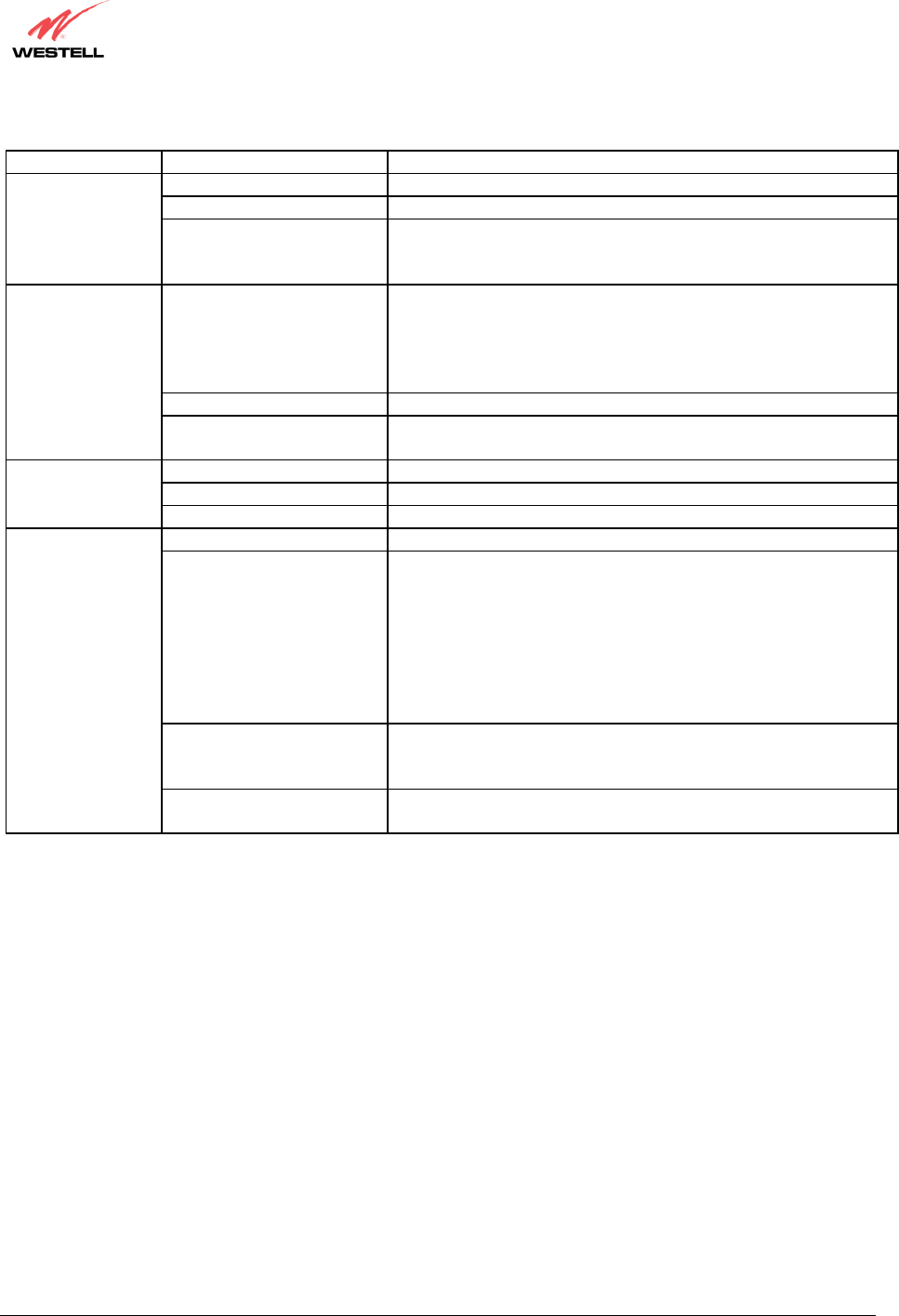
5.1 LED Indicators
This section explains the LED States and Descriptions of your Router. LED indicators are used to verify the unit’s
operation and status. Please refer to the table of the Model you are using.
LED States and Descriptions (Model 7400)
LED State Description
Solid Green Modem power is ON.
OFF Modem power is OFF.
POWER
Solid Red
POST (Power On Self Test), Failure (not bootable) or Device
Malfunction. Note: The Power LED should be red no longer than
two seconds after the power on self test passes.
Solid Green
Powered device is connected to the associated port (includes
devices with wake-on LAN capability where slight voltage is
supplied to an Ethernet connection).
Note: When using the optional UPLINK/E1 port (E1), Ethernet
LAN connection is limited to E2, E3, and E4.
Flashing Green 10/100 Base-T LAN activity is present (traffic in either direction)
ETHERNET
(E1, E2, E3, E4)
OFF Modem power is OFF, no cable or no powered device is
connected to the associated port.
Solid Green USB link established
Flashing Green Transmit or Receive Activity
USB
OFF No USB link established
Solid Green Good DSL sync.
Flashing Green DSL attempting to sync.
DSL
OFF Modem power is OFF.
Solid Green Internet link established.
Flashing Green
IP connection established and IP Traffic is passing through
device (in either direction).
Note: If the IP or PPP session is dropped due to an idle timeout,
the light will remain solid green, if an ADSL connection is still
present.
If the session is dropped for any other reason, the light is turned
OFF. The light will turn red when it attempts to reconnect and
DHCP or PPP fails).
Solid Red
Device attempted to become IP connected and failed (no DHCP
response, no PPP response, PPP authentication failed, no IP
address from IPCP, etc.).
INTERNET
OFF Modem power is OFF, Modem is in Bridge Mode, or the
connection is not present.
NOTE: Safe Boot is reflected when the Power and Internet LED’s are both Red and all other LED’s are off.
030-300432 Rev. A 10 December 2004
User Guide
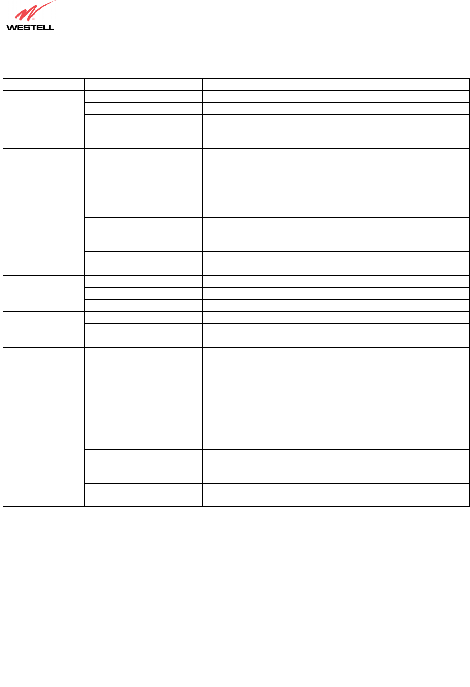
LED States and Descriptions (Model 7401)
LED State Description
Solid Green Modem power is ON.
OFF Modem power is OFF.
POWER
Solid Red
POST (Power On Self Test), Failure (not bootable) or Device
Malfunction. Note: The Power LED should be red no longer than
two seconds after the power on self test passes.
Solid Green
Powered device is connected to the associated port (includes
devices with wake-on LAN capability where slight voltage is
supplied to an Ethernet connection).
Note: When using the optional UPLINK/E1 port (E1), Ethernet
LAN connection is limited to E2, E3, and E4.
Flashing Green 10/100 Base-T LAN activity is present (traffic in either direction)
ETHERNET
(E1, E2, E3, E4)
OFF Modem power is OFF, no cable or no powered device is
connected to the associated port.
Solid Green Good DSL sync.
Flashing Green DSL attempting to sync.
DSL
OFF Modem power is OFF.
Solid Green Internet link established.
Flashing Green
IP connection established and IP Traffic is passing through
device (in either direction).
Note: If the IP or PPP session is dropped due to an idle timeout,
the light will remain solid green, if an ADSL connection is still
present.
If the session is dropped for any other reason, the light is turned
OFF. The light will turn red when it attempts to reconnect and
DHCP or PPP fails).
Solid Red
Device attempted to become IP connected and failed (no DHCP
response, no PPP response, PPP authentication failed, no IP
address from IPCP, etc.).
INTERNET
OFF Modem power is OFF, Modem is in Bridge Mode, or the
connection is not present.
NOTE: Safe Boot is reflected when the Power and Internet LED’s are both Red and all other LED’s are off.
030-300432 Rev. A 11 December 2004
User Guide
LED States and Descriptions (Model 328W10)
LED State Description
Solid Green Modem power is ON.
OFF Modem power is OFF.
POWER
Solid Red
POST (Power On Self Test), Failure (not bootable) or Device
Malfunction. Note: The Power LED should be red no longer than
two seconds after the power on self test passes.
Solid Green
Powered device is connected to the associated port (includes
devices with wake-on LAN capability where slight voltage is
supplied to an Ethernet connection).
Note: When using the optional UPLINK/E1 port (E1), Ethernet
LAN connection is limited to E2, E3, and E4.
Flashing Green 10/100 Base-T LAN activity is present (traffic in either direction)
ETHERNET
(UPLINK/E1, E2,
E3, E4)
OFF Modem power is OFF, no cable or no powered device is
connected to the associated port.
Solid Green Link Established.
Flashing Green Wireless LAN activity is present (traffic in either direction).
WIRELESS
OFF Modem power is OFF or No Link.
Solid Green USB link established
Flashing Green Transmit or Receive Activity
USB
OFF No USB link established
Solid Green Good DSL sync.
Flashing Green DSL attempting to sync.
DSL
OFF Modem power is OFF.
Solid Green Internet link established.
Flashing Green
IP connection established and IP Traffic is passing through
device (in either direction).
Note: If the IP or PPP session is dropped due to an idle timeout,
the light will remain solid green, if an ADSL connection is still
present.
If the session is dropped for any other reason, the light is turned
OFF. The light will turn red when it attempts to reconnect and
DHCP or PPP fails).
Solid Red
Device attempted to become IP connected and failed (no DHCP
response, no PPP response, PPP authentication failed, no IP
address from IPCP, etc.).
INTERNET
OFF Modem power is OFF, Modem is in Bridge Mode, or the
connection is not present.
NOTE: Safe Boot is reflected when the Power and Internet LED’s are both Red and all other LED’s are off.
030-300432 Rev. A 12 December 2004
User Guide
LED States and Descriptions (Model 328W11)
LED State Description
Solid Green Modem power is ON.
OFF Modem power is OFF.
POWER
Solid Red
POST (Power On Self Test), Failure (not bootable) or Device
Malfunction. Note: The Power LED should be red no longer than
two seconds after the power on self test passes.
Solid Green
Powered device is connected to the associated port (includes
devices with wake-on LAN capability where slight voltage is
supplied to an Ethernet connection).
Note: When using the optional UPLINK/E1 port (E1), Ethernet
LAN connection is limited to E2, E3, and E4.
Flashing Green 10/100 Base-T LAN activity is present (traffic in either direction)
ETHERNET
(UPLINK/E1, E2,
E3, E4)
OFF Modem power is OFF, no cable or no powered device is
connected to the associated port.
Solid Green Link Established.
Flashing Green Wireless LAN activity is present (traffic in either direction).
WIRELESS
OFF Modem power is OFF or No Link.
Solid Green Good DSL sync.
Flashing Green DSL attempting to sync.
DSL
OFF Modem power is OFF.
Solid Green Internet link established.
Flashing Green
IP connection established and IP Traffic is passing through
device (in either direction).
Note: If the IP or PPP session is dropped due to an idle timeout,
the light will remain solid green, if an ADSL connection is still
present.
If the session is dropped for any other reason, the light is turned
OFF. The light will turn red when it attempts to reconnect and
DHCP or PPP fails).
Solid Red
Device attempted to become IP connected and failed (no DHCP
response, no PPP response, PPP authentication failed, no IP
address from IPCP, etc.).
INTERNET
OFF Modem power is OFF, Modem is in Bridge Mode, or the
connection is not present.
NOTE: Safe Boot is reflected when the Power and Internet LED’s are both Red and all other LED’s are off.
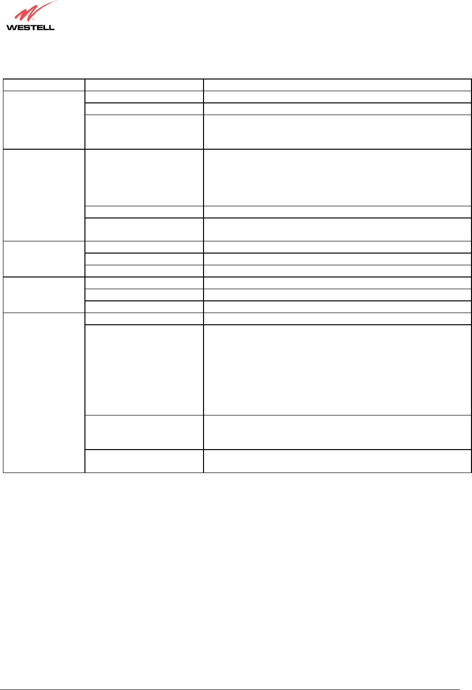
5.2 Cable Connectors and Switch Locations
• DSL connector (RJ-11)
• USB connector (Models 7400, 328W10 only)
• Reset button
• (4) Ethernet connector (RJ-45) with optional uplink port
(Note: When using the optional UPLINK/E1 port (E1), Ethernet LAN connection is limited to E2, E3, and E4.
Models 328W10, 328W11 only)
• Power connector (barrel)
• ON/OFF Switch
• Wireless IEEE 802.11b/g SMA connector and antenna (Models 328W10, 328W11 only)
030-300432 Rev. A 13 December 2004
User Guide
Model 7400 Rear View
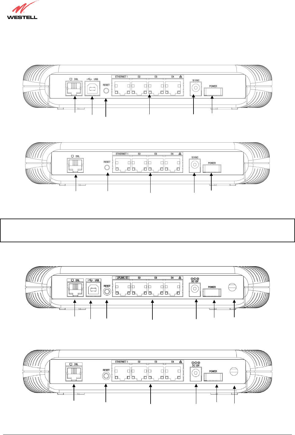
Model 7401 Rear View
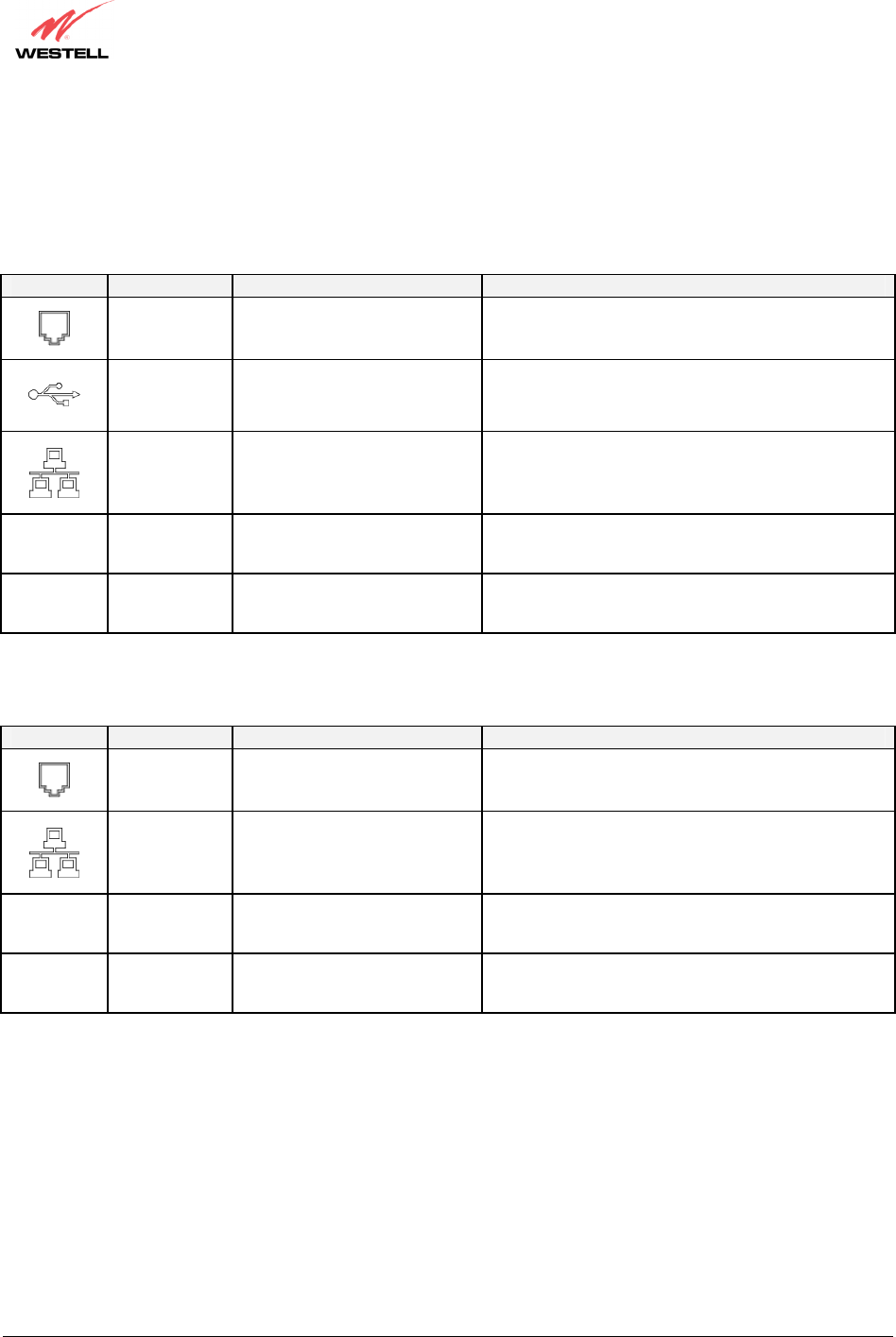
NOTE: For Models 328W10 and 328W11, when using the optional UPLINK/E1 or ETHERNET 1 ports, Ethernet
LAN connection is limited to E2, E3, and E4. The UPLINK feature is optional. If UPLINK feature is not enabled,
the Router will use DSL and Wireless only.
Model 328W10 Rear View
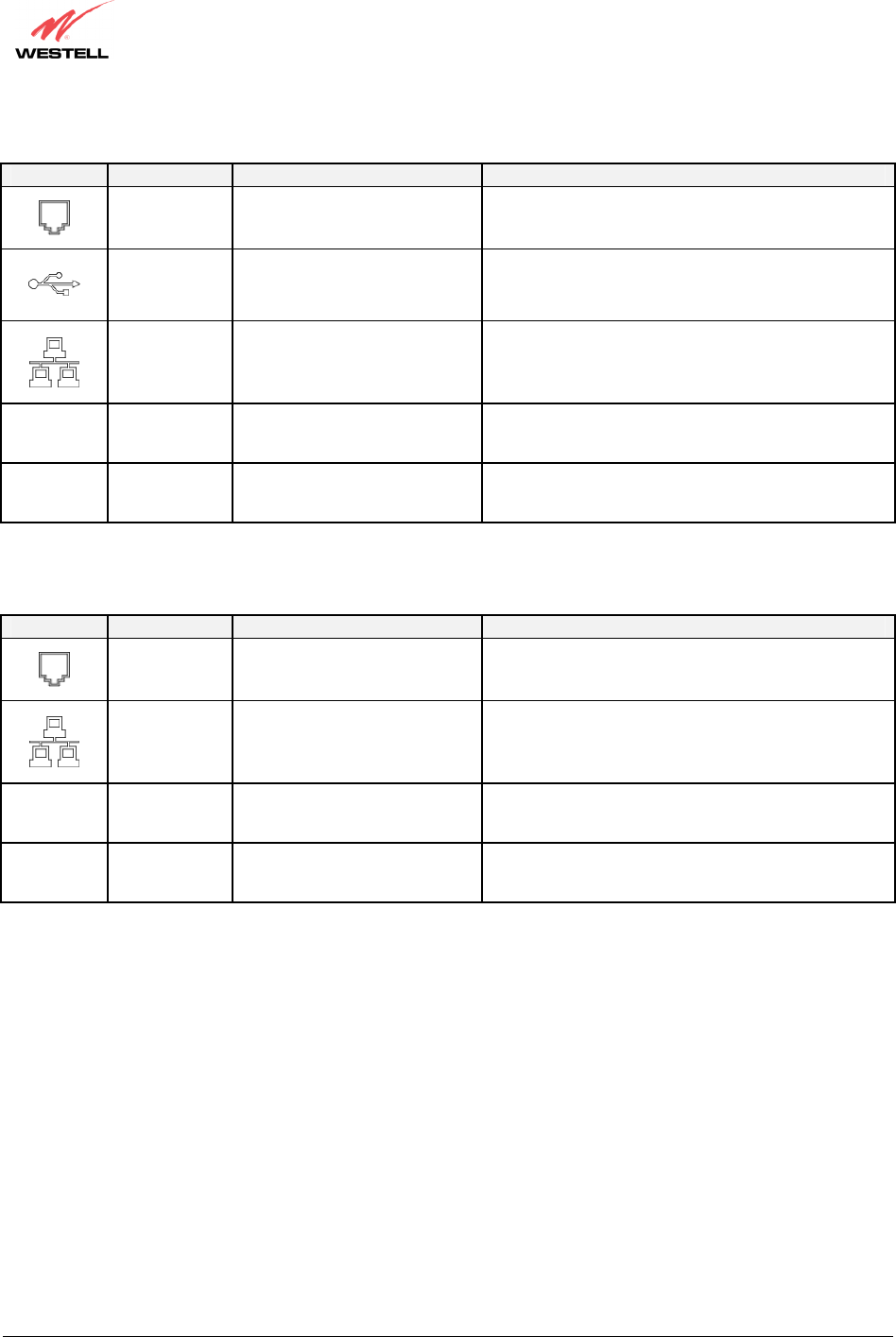
Model 328W11 Rear View
Ethernet Connectors
(E1 through E4)
DSL Line
Connector
ON/OFF
Switch
Power
Connector
Ethernet Connectors
(E1 through E4)
Reset
Button
Wireless Antenna
Connector
DSL Line
Connector
ON/OFF
Switch
Power
Connector
Ethernet Connectors
(E1 through E4)
Reset
Button
USB
Connecto
r
DSL Line
Connector
ON/OFF
Switch
Power
Connector
Ethernet Connectors
(E1 through E4)
Reset
Button
USB
Connecto
r
DSL Line
Connector ON/OFF
Switch
Power
Connector
Reset
Button Wireless Antenna
Connector
030-300432 Rev. A 14 December 2004
User Guide
5.3 Connector Descriptions
The following chart displays the connector types for the Model you are using.
Model 7400
SYMBOL NAME TYPE FUNCTION
DSL LINE 6-pin RJ-11 modular jack
Connects to an ADSL-equipped telephone jack or
DSL connection of a POTS splitter.
USB 4-pin USB Series B connector Connects the USB device to the PC.
ETHERNET 8-pin (RJ-45) modular jack Connects the Ethernet device to the PC.
15 VAC POWER Barrel connector Power source.
Wireless ANTENNA SMA connector and antenna Connects to wireless IEEE 802.11b/g/g+
Model 7401
SYMBOL NAME TYPE FUNCTION
DSL LINE 6-pin RJ-11 modular jack
Connects to an ADSL-equipped telephone jack or
DSL connection of a POTS splitter.
ETHERNET 8-pin (RJ-45) modular jack Connects the Ethernet device to the PC.
15 VAC POWER Barrel connector Power source.
Wireless ANTENNA SMA connector and antenna Connects to wireless IEEE 802.11b/g/g+
030-300432 Rev. A 15 December 2004
User Guide
Model 328W10
SYMBOL NAME TYPE FUNCTION
DSL LINE 6-pin RJ-11 modular jack
Connects to an ADSL-equipped telephone jack or
DSL connection of a POTS splitter.
USB 4-pin USB Series B connector Connects the USB device to the PC.
ETHERNET 8-pin (RJ-45) modular jack Connects the Ethernet device to the PC.
DC 12V POWER Barrel connector Power source.
Wireless ANTENNA SMA connector and antenna Connects to wireless IEEE 802.11b/g/g+
Model 328W11
SYMBOL NAME TYPE FUNCTION
DSL LINE 6-pin RJ-11 modular jack
Connects to an ADSL-equipped telephone jack or
DSL connection of a POTS splitter.
ETHERNET 8-pin (RJ-45) modular jack Connects the Ethernet device to the PC.
DC 12V POWER Barrel connector Power source.
Wireless ANTENNA SMA connector and antenna Connects to wireless IEEE 802.11b/g/g+
030-300432 Rev. A 16 December 2004
User Guide
5.4 Pin-out Descriptions
The following tables list the pin-out descriptions.
DSL Pin-outs (Models 7400, 7401, 328W10, 328W11)
Pin-out Description
1, 2, 5, 6 Not Used
3 DSL Tip
4 DSL Ring
USB Pin-outs (Models 7400, 328W10)
Pin Name Description Cable Color
1 VBUS/Vcc 5 Vdc Red
2 D – Data – White
3 D + Data + Green
4 GND Ground Black
Optional UPLINK/E1, E2, E3, and E4 (Ethernet) Port Pin-outs (Models 328W10, 328W11)
Pin-out Description
1 Rx+
2 Rx-
3 Tx+
4,5,7,8 Not Used
6 Tx-
E1, E2, E3, E4 (Ethernet) Port Pin-outs (Models 7400, 7401)
Pin-out Description
1 Rx+
2 Rx-
3 Tx+
4,5,7,8 Not Used
6 Tx-

030-300432 Rev. A 17 December 2004
User Guide
6. INSTALLING THE HARDWARE
6.1 Installation Requirements
To install your Router, you will need the following:
• A Network Interface Card (NIC) installed in your PC
• An IEEE 802.11b/g adapter (Models 328W10, 328W11 only)
NOTE: Internet service provider subscriber software and connection requirements may vary. Consult your ISP for
installation instructions. Please wait until you have received notification from your ISP that your DSL line has been
activated before installing the Router and the software.
6.2 Before you begin
Make sure your kit contains the following items:
• Westell® Router
• Power Supply
• RJ-45 Ethernet cable (straight-through) (yellow)
• USB Cable (blue) (Models 7400, 328W10 only)
• RJ-11 Phone cable
• SMA Antenna (Models 328W10, 328W11 only)
• Westell CD-ROM containing User Guide in PDF format
• Quick Start Guide
6.3 Microfilters
ADSL signals must be blocked from reaching each telephone, answering machine, fax machine, computer modem
or any similar conventional device. Failure to do so may degrade telephone voice quality and ADSL performance.
Install a microfilter if you desire to use the DSL-equipped line jack for telephone, answering machine, fax machine
or other telephone device connections. Microfilter installation requires no tools or telephone rewiring. Just unplug
the telephone device from the baseboard or wall mount and snap in a microfilter, next snap in the telephone device.
You can purchase microfilters from your local electronics retailer, or contact the original provider of your DSL
equipment.
030-300432 Rev. A 18 December 2004
User Guide
6.4 Hardware Installations
NOTE: If you are using the Router in conjunction with an Ethernet Hub or Switch, refer to the manufacturer’s
instructions for proper installation and configuration. When using a Microfilter, be certain that the DSL phone cable
is connected to the “DSL/HPN” non-filtered jack. Please wait until you have received notification from your ISP
that your DSL line has been activated before installing the Router. Westell recommends the use of a surge
suppressor to protect equipment attached to the power supply.
6.4.1 Installation via 10/100 Base-T Ethernet
IMPORTANT: Before you connect via 10/100 Base-T, you must have an available Ethernet card installed
in your computer. If your Ethernet card does not auto-negotiate, you must set it to half duplex. Refer to the
Ethernet card manufacturer’s instructions for installing and configuring your Ethernet card.
Warning: Your power requirements may differ from those displayed in the following instructions. You must use
only the power adapter provided with your kit.
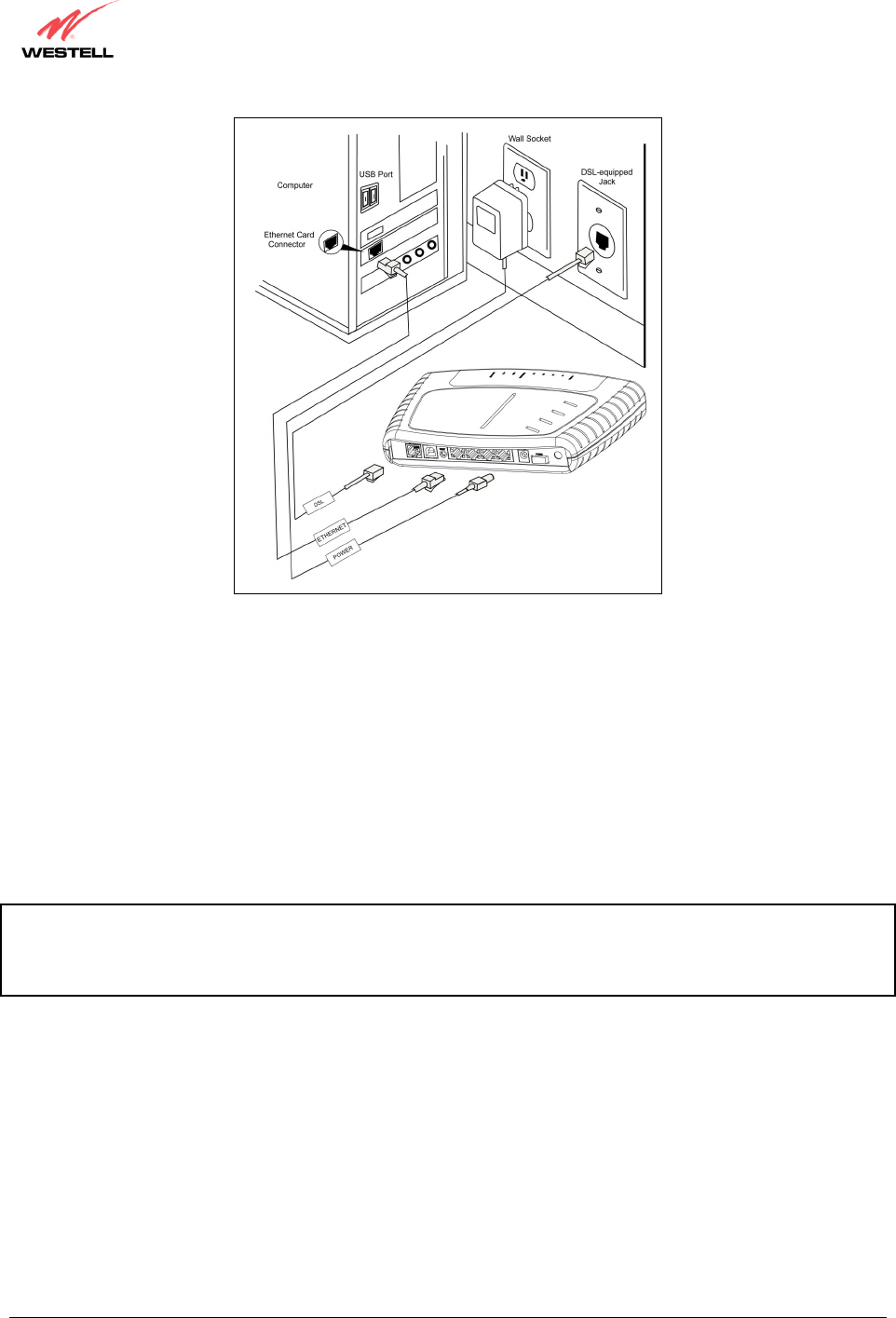
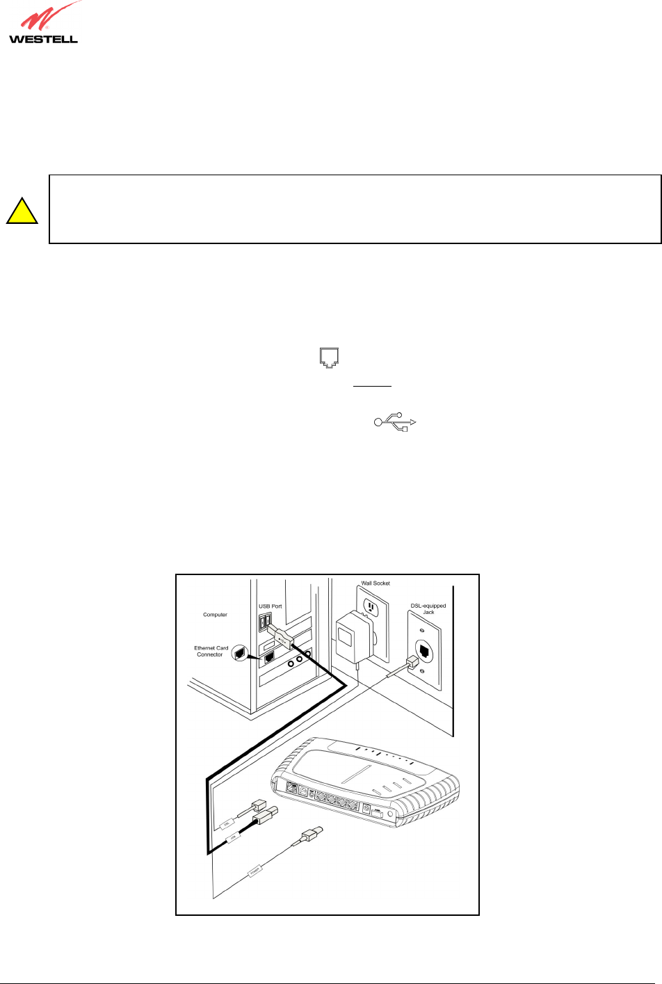
1. Connect the power supply cord to the power connector marked 15 VAC on the rear panel of the Router. Plug
the other end of the power supply into a wall socket.
2. Connect the DSL phone cable from the connector marked DSL on the rear panel of the Router to the DSL-
equipped telephone line jack on the wall. IMPORTANT: Do not use a DSL filter on this connection. You must
use the phone cord that was provided with the kit.
3. Connect the yellow Ethernet cable from any one of the Ethernet jacks marked
on the rear panel of the
Router to the Ethernet port on your computer. Repeat this step to connect up to three additional PCs to your
Westell Router.
NOTE: You may connect to any of the four Ethernet jacks on the rear panel as they serve as an Ethernet switch.
However, when using the optional UPLINK/E1 port, Ethernet LAN connection is limited to ports E2, E3, and E4.
4. Check to see if the DSL LED is solid green. If the DSL LED is solid green, the Router is functioning properly.
5. Check to see if the Ethernet LED is solid green. Solid green indicates that the Ethernet connection is
functioning properly.
Congratulations! You have completed the Ethernet hardware installation. No software installation is required when using
only an Ethernet connection. You must now proceed to section 8 to configure your Router for Internet connection.
!
030-300432 Rev. A 19 December 2004
User Guide
Figure 1. Connection via 10/100 Base-T Ethernet
6.4.2 Connecting PCs via Wireless (Models 328W10, 328W11)
IMPORTANT: If you are connecting to the Router via a wireless network adapter, the SSID must be the same for
both the Router and your PC’s wireless network adapter. The default SSID for the Router is the serial number of the
unit (located below the bar code on the bottom of the unit and also on the Westell shipping carton). Locate and run
the utility software provided with your PC’s Wireless network adapter and enter the SSID value. The PC’s wireless
network adapter must be configured with the SSID (in order to communicate with the Router) before you begin the
account setup and configuration procedures. Later, for privacy you can change the SSID by following the
procedures outlined in section 13.4 (Wireless Configuration).
IMPORTANT: Client PCs can use any Wireless Fidelity (Wi-Fi) 802.11b/g/g+ certified card to communicate with
the Router. The Wireless card and Router must use the same security code type. If you use WPA-PSK or WEP
wireless security, you must configure your computer’s wireless adapter for the security code that you use.
You can access the settings in the advanced properties of the wireless network adapter.
030-300432 Rev. A 20 December 2004
User Guide
Warning: Your power requirements may differ from those displayed in the following instructions. You must use
only the power adapter provided with your kit.
To network the Router to additional computers in your home or office using a wireless installation, you will need to
confirm the following:
1. Ensure that an 802.11b/g/g+ wireless network adapter has been installed in each PC on your wireless network.
2. Install the appropriate drivers for your Wireless IEEE802.11b or IEEE802.11g adapter.
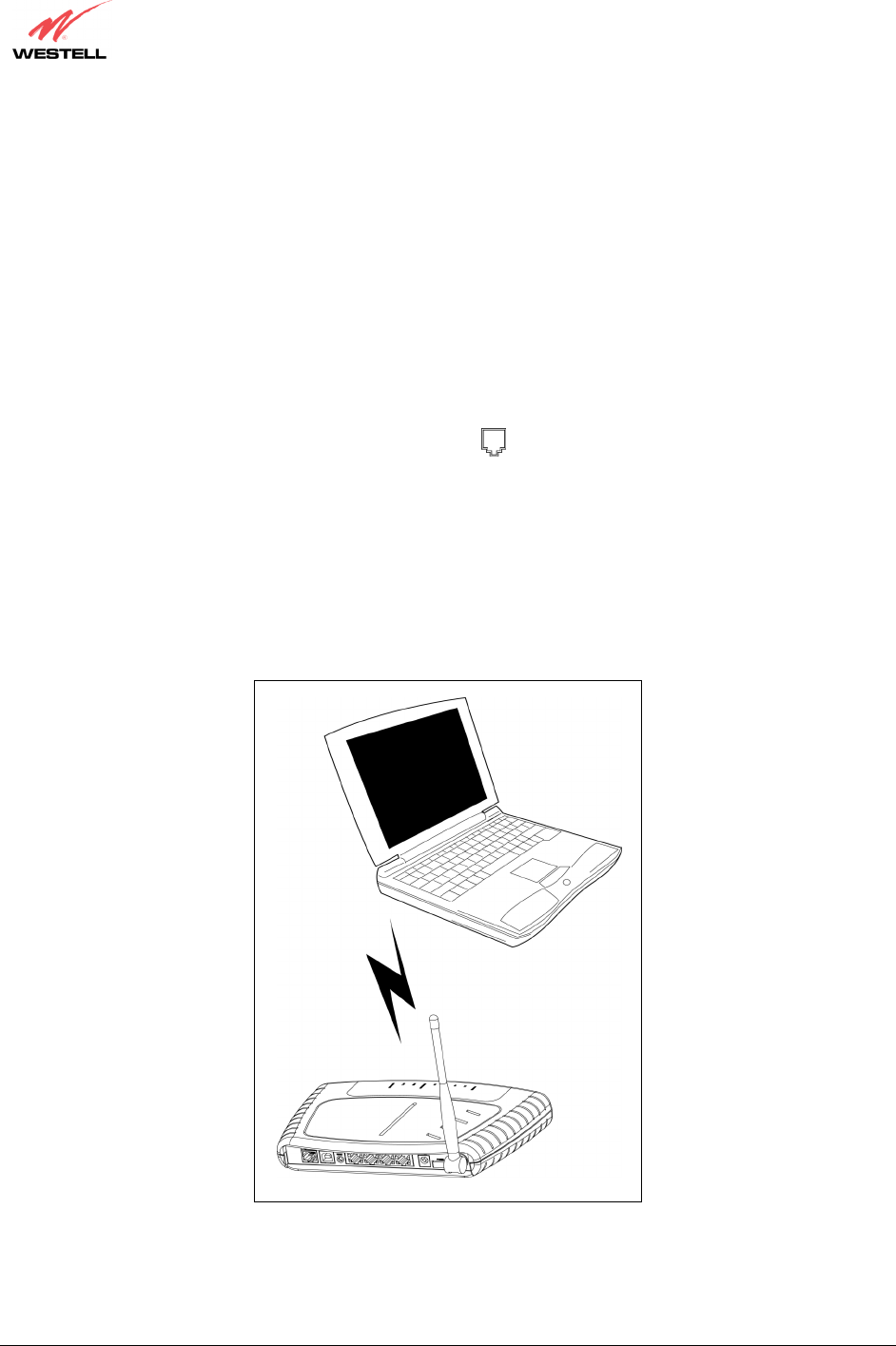
3. Make sure the SMA antenna connector is loose. Orient the antenna in the proper configuration. Then, tighten
the antenna knob to lock it into place.
4. Connect the power supply cord to the power connector marked 15 VAC on the rear panel of the Router. Plug
the other end of the power supply into a wall socket.
5. Connect the DSL phone cable from the connector marked DSL on the rear panel of the Router to the DSL-
equipped telephone line jack on the wall. IMPORTANT: Do not use a DSL filter on this connection. You must
use the phone cord that was provided with the Router kit.
6. Check to see if the DSL LED is solid Green. If the DSL LED is solid Green, the Router is functioning properly.
7. Check to see if the Router’s Wireless LED is solid Green. This means that the Wireless interface is functioning
properly.
Congratulations! You have completed the Wireless installation for the Router. You must now proceed section 8 to
configure your Router for Internet connection.
Figure 2. Connection via Wireless
030-300432 Rev. A 21 December 2004
User Guide
6.4.3 Installation via Ethernet and Wireless Combination (Models 328W10,
328W11)
The Router supports simultaneous use of 10/100 Base-T Ethernet and Wireless configurations. The following
instructions explain how to install the Router for simultaneous use of Ethernet and Wireless ports.
NOTE: Refer to Figure 1 and Figure 2 for instructions on hardware installation via Ethernet and Wireless
connections.
Warning: Your power requirements may differ from those displayed in the following instructions. You must use
only the power adapter provided with your kit.
1. Ensure that an 802.11b/g/g+ wireless network adapter has been installed in each PC on your wireless network
2. Install the appropriate drivers for your Wireless IEEE802.11b or IEEE802.11g adapter.
3. Make sure the SMA antenna connector is loose. Orient the antenna in the proper configuration. Then, tighten
the antenna knob to lock it into place.
4. Connect the power supply cord to the power connector marked 15 VAC on the rear panel of the Router. Plug
the other end of the power supply into a wall socket.
5. Connect the DSL phone cable from connector marked DSL on the rear panel of the Router to the DSL-
equipped telephone line jack on the wall. IMPORTANT: Do not use a DSL filter on this connection. You must
use the phone cord that was provided with the kit.
6. Connect the yellow Ethernet cable from any one of the Ethernet jacks marked
on the rear panel of the
Router to the Ethernet port on your computer. Repeat this step to connect up to three additional PCs to your
Westell Router.
NOTE: You may connect to any of the four Ethernet jacks on the rear panel as they serve as an Ethernet switch.
However, when using the optional UPLINK/E1 port, Ethernet LAN connection is limited to ports E2, E3, and E4.
7. Check to see if the DSL LED is solid green. If the DSL LED is solid green, the Router is functioning properly.
8. Check to see if the Ethernet LED is solid green. Solid green indicates that the Ethernet connection is
functioning properly.
9. Check to see if the Router’s Wireless LED is solid green. This means that the Wireless interface is functioning
properly.
Congratulations! You have completed the simultaneous hardware (Ethernet and Wireless) installation. You must now
proceed to section 8 to configure your Router for Internet connection.
030-300432 Rev. A 22 December 2004
User Guide
6.4.4 Installation via USB (Models 7400, 328W10)
Westell recommends using the Router via Wireless or Ethernet connections. However, if you choose to connect via
USB, you must follow the instructions in this section.
IMPORTANT: The USB installation will not function for Macintosh computers. Macintosh computers
must install via Ethernet connection. See section 6.4.1 for Ethernet installation instructions. Prior to
installing the Router via USB, confirm that the CD-ROM provided with your Router kit is inserted
in your computer’s CD-ROM drive.
Warning: Your power requirements may differ from those displayed in the following instructions. You must use
only the power adapter provided with your kit.
1. Connect the power supply cord to the power connector marked 15 VAC on the rear panel of the Router. Plug
the other end of the power supply into a wall socket.
2. Connect the DSL phone cable from the jack marked DSL on the rear panel of the Router to the DSL-
equipped telephone line jack on the wall. IMPORTANT: Do not use a DSL filter on this connection. You must
use the phone cord that was provided with the kit.
3. Connect the blue USB cable from the USB connector marked USB on the rear panel of the Router to
the USB port on the PC. You must now go to section 7 for instructions on installing the USB drivers.
4. Check to see if the DSL LED is solid green. If the DSL LED is solid green, the Router is functioning properly.
5. Check to see if the USB LED is solid green. Solid green indicates that the USB connection is functioning properly.
Congratulations! You have completed the USB hardware installation. You must now proceed to section 8 to
configure your Router for Internet connection.
Figure 3. Connection via USB
!
030-300432 Rev. A 23 December 2004
User Guide
7. INSTALLING THE USB DRIVERS (MODELS 7400, 328W10)
If you are using only Ethernet or Wireless connections, USB driver installation is not necessary. The Microsoft®
Plug and Play auto-detect feature recognizes when new hardware has been installed. After you connect the Router to
the PC, the Router will be detected automatically.
Before you begin the USB software installation, determine which operating system is installed on your PC, and then
follow the installation instructions that match your operating system. When the installation has completed, proceed
to section 8 in the User Guide to configure the Router for Internet connection. The following table provides a
reference to the USB driver installation instructions.
Your Operating System Refer to this section for USB driver instructions
Windows 98 SE Installing the USB Driver for Windows 98 SE
Windows ME Installing the USB Driver for Windows ME
Windows 2000 Installing the USB Driver for Windows 2000
Windows XP Installing the USB Driver for Windows XP
7.1 CD-ROM Installation:
1. Place the CD-ROM that you received in the Router kit into the CD-ROM drive of the PC that is connected to
the USB port.
2. Verify the connection to the computer by observing the state of the USB LED. Once the USB drivers have been
installed, the USB LED should be solid green. Solid green indicates a USB connection has been established.
3. Go to the USB driver installation section that matches your operating system and follow the procedures outlined
in that section.
NOTE: The actual information displayed in the USB screens may vary according to product.
7.2 Installing the USB Drivers for Windows 98 SE
IMPORTANT: Confirm that the CD-ROM provided with the Router kit is inserted in the
appropriate drive before continuing this installation.
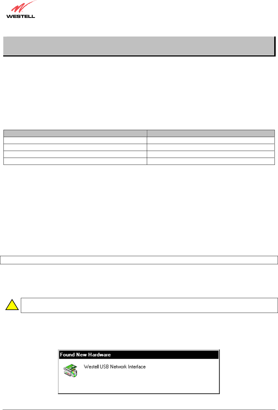
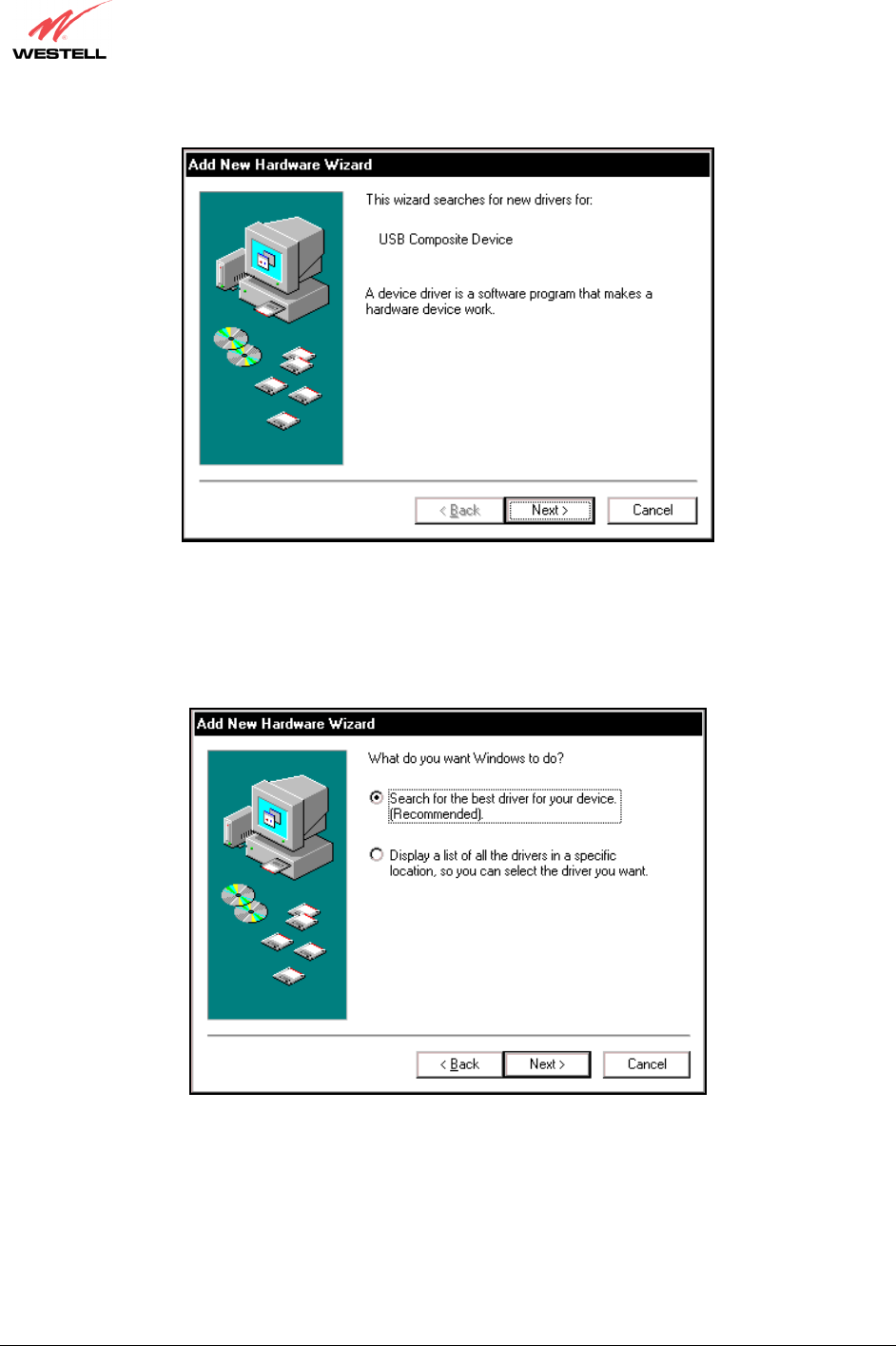
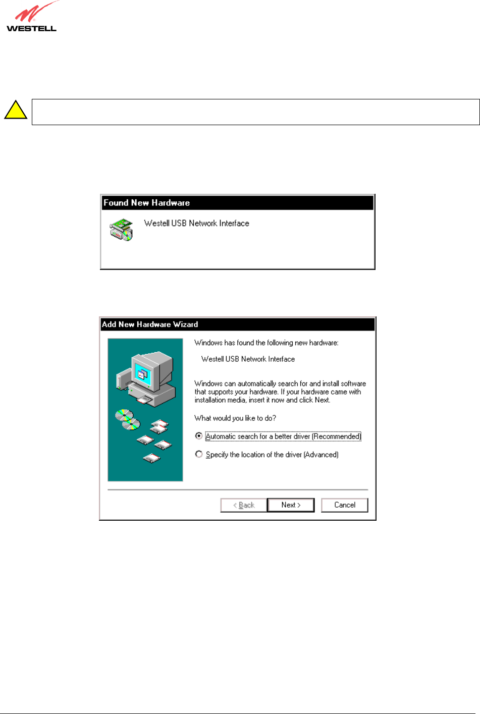
1. Windows 98 SE: After you connect the Router to your PC, the Found New Hardware window will appear
(Figure 4). After a brief delay, the Add New Hardware Wizard window will appear (Figure 5) Click Next.
Figure 4. Windows 98 SE
!
030-300432 Rev. A 25 December 2004
User Guide
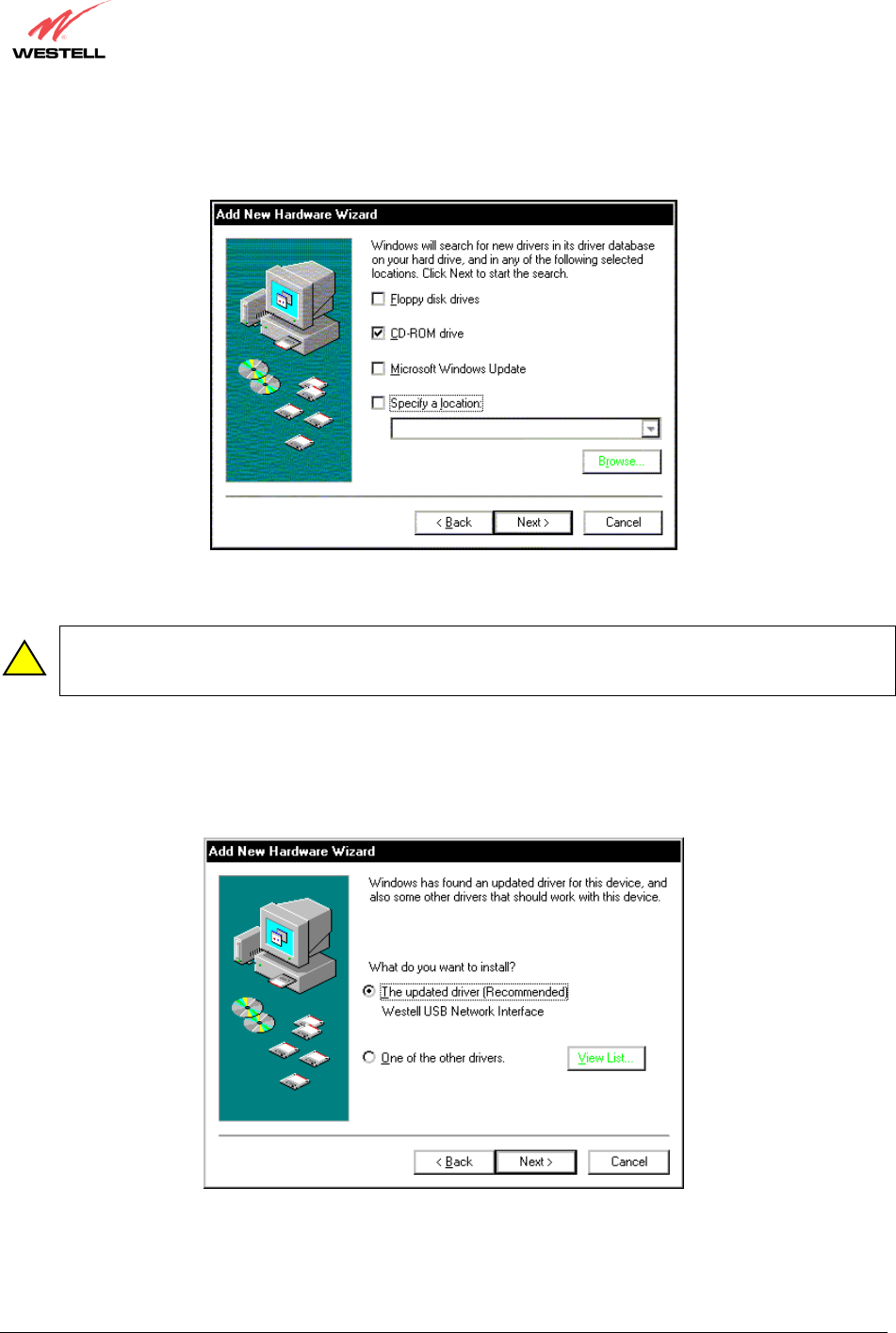
3. Windows 98 SE: Select CD-ROM drive (Figure 7). Click Next. Windows will search for the driver.
Figure 7. Windows 98 SE
Note: If Figure 7 does not appear at this step, and Figure 8 appears with the text ‘USB Composite device’,
‘C:\Windows\Inf\USB.Inf’, do not continue. Click Back to Step 3 and specify the location of the Westell
CD-ROM.
4. Windows 98 SE: Select The updated driver (Recommended) Westell USB Network Interface (Figure 8).
Click Next.
Figure 8. Windows 98 SE
!
030-300432 Rev. A 26 December 2004
User Guide
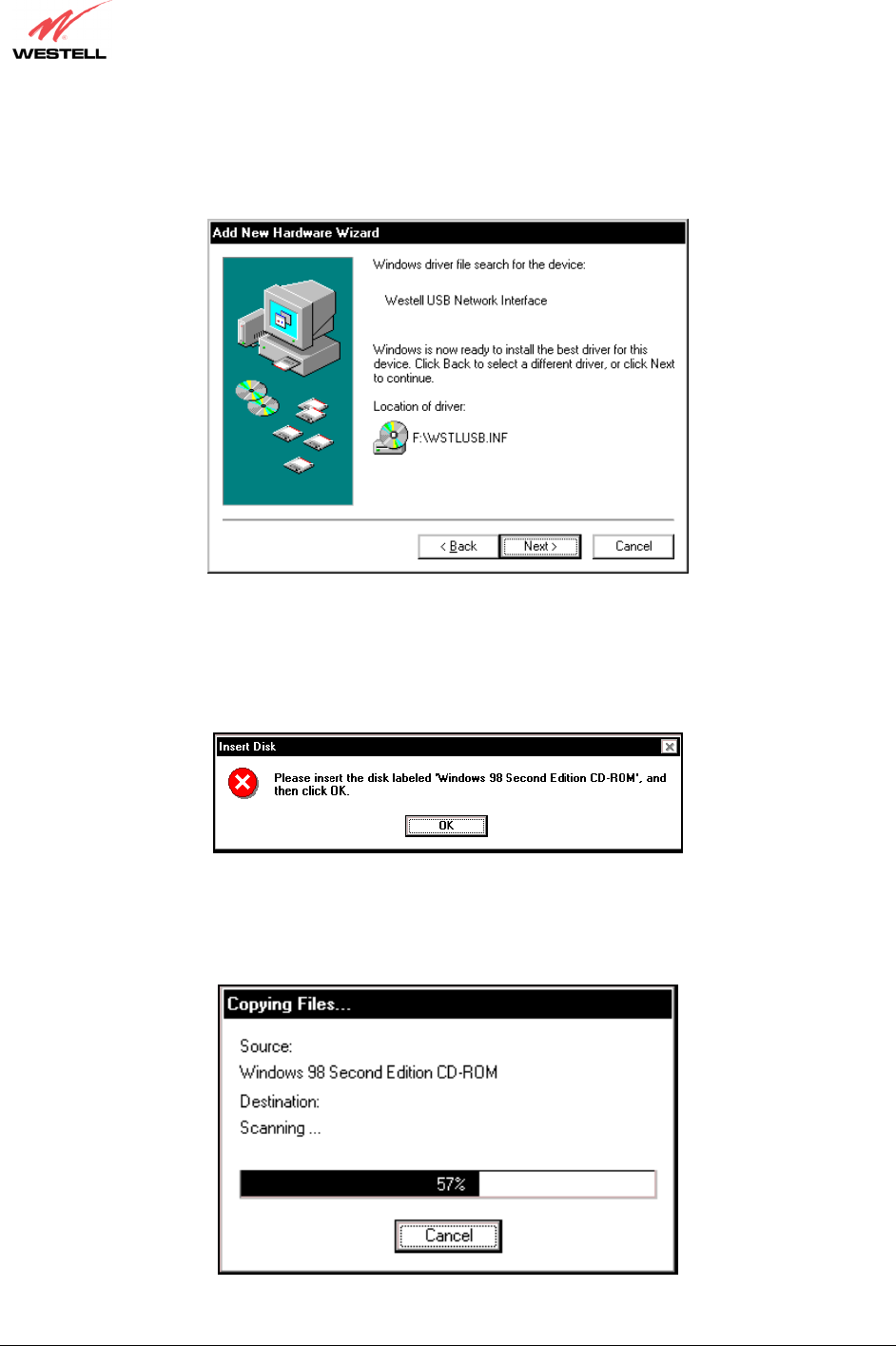
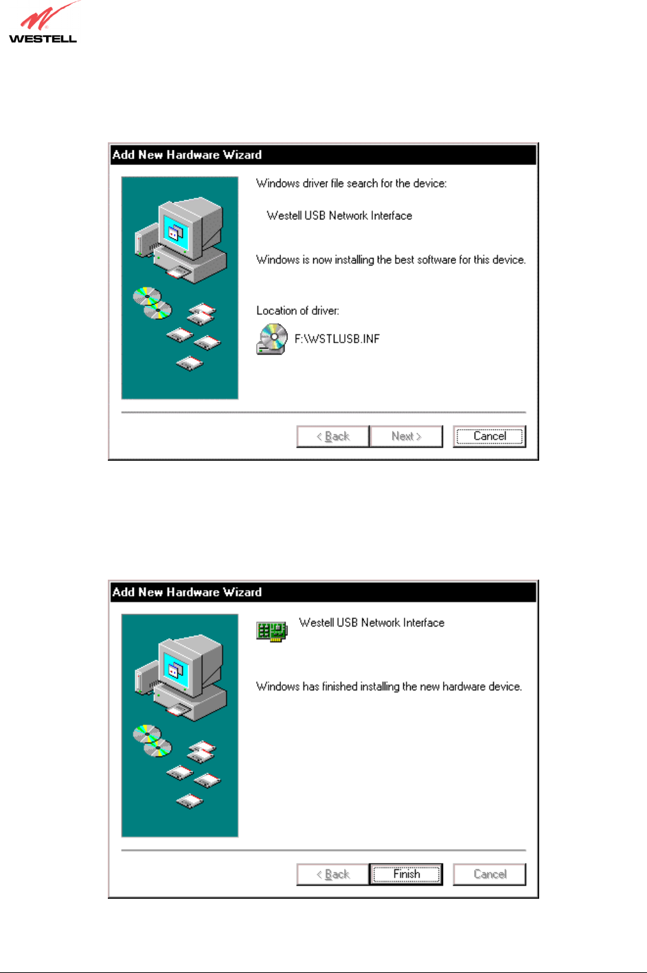
5. Windows 98 SE: Windows will display the location of the driver (Figure 9). The drive “letter” may vary. Click
Next.
Figure 9. Windows 98 SE
6. Windows 98 SE: Remove the Westell CD from the CD-ROM Drive. Next, insert the Windows operating
system CD into the CD-ROM Drive (Figure 10). Click OK.
Figure 10. Windows 98 SE
7. Windows 98 SE: The system will begin copying files (Figure 11).
Figure 11. Windows 98 SE
030-300432 Rev. A 27 December 2004
User Guide
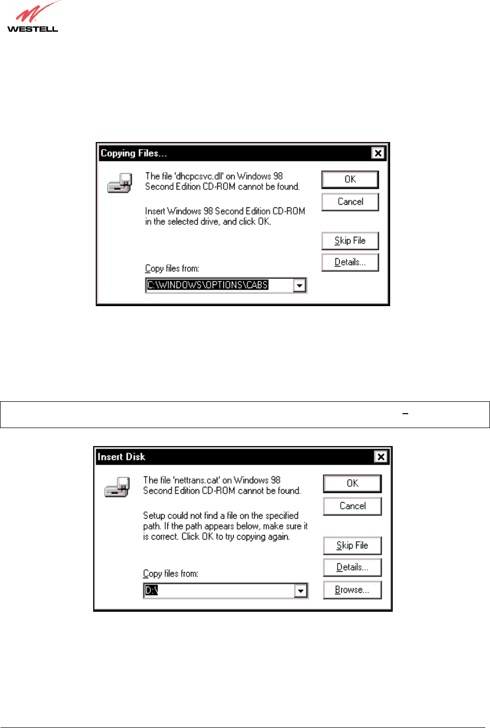
8. Windows 98 SE: Figure 12 may pop up, depending on how Windows 98 SE was installed on the computer. The
installation of the Westell Router requires files that are supplied by Microsoft for Windows 98 SE. If Figure 13
pops up, insert the Windows 98 SE Operating System CD into the computers CD-ROM drive, wait a moment for
the CD to be recognized by the system, and then click on OK. The system should find the required files on the
Windows 98 SE CD-ROM and automatically complete the installation.
Figure 12. Windows 98 SE
If the Operating System CD is not available, or if Figure 12 pops up again, you will have to manually specify the
location of the files. The required files may be stored on your hard drive. A common location for these files is
"C:\Windows\Options\Cabs." Try specifying this path or the path to your CD-ROM drive (usually "D:\") by clicking
the Browse… button in the Insert Disk screen (Figure 13). When you have specified the correct path, click on OK.
The system will begin copying the files.
NOTE: It is very important that the Windows 98 SE files be installed. Do not click on Cancel or Skip File in the
dialogs, doing so will result in an improper installation and the Router will not function correctly.
Figure 13. Windows 98 SE
030-300432 Rev. A 28 December 2004
User Guide
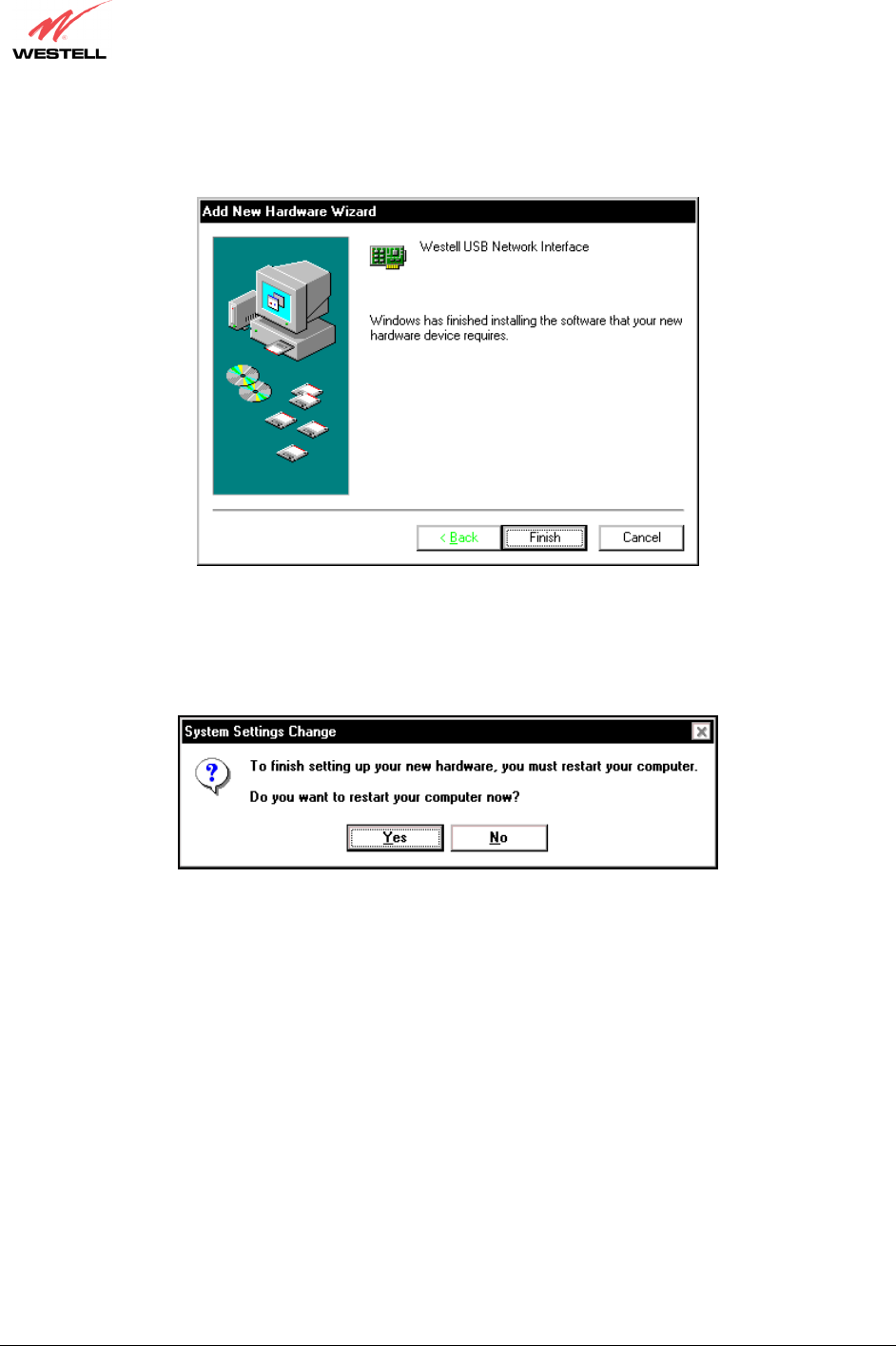
9. Windows 98 SE: The window below confirms that the PC has finished loading the drivers (Figure 14). Click
Finish.
Figure 14. Windows 98 SE
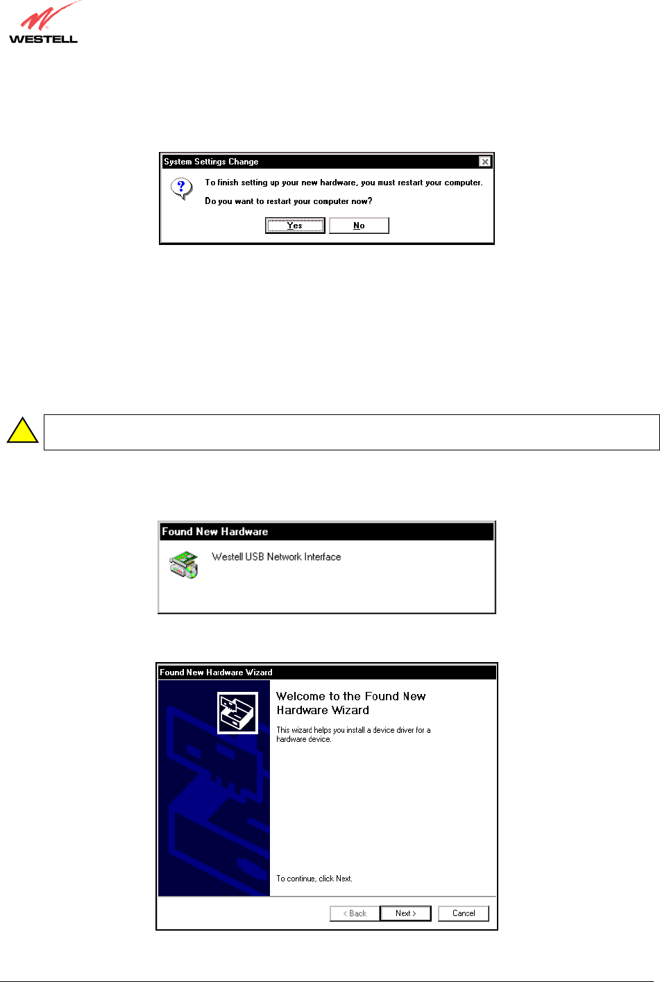
10. Windows 98 SE: Click Yes to restart your computer (Figure 15).
Figure 15. Windows 98 SE
Congratulations! You have completed the software installation for the USB drivers. After you have finished
installing the USB drivers, you must return to section 6.4.4 (Installation via USB) to complete the installation
instructions.
030-300432 Rev. A 29 December 2004
User Guide
7.3 Installing the USB Drivers for Windows ME
IMPORTANT: Confirm that the CD-ROM provided with the Router kit is inserted in the
appropriate drive before continuing this installation.
1. Windows ME: After you connect the Router to your PC, the Found New Hardware window will appear
(Figure 16). After a brief delay, the Add New Hardware Wizard will appear (Figure 17). Select Automatic
search for a better driver (Recommended). Click Next.
Figure 16. Windows ME
Figure 17. Windows ME
!
030-300432 Rev. A 31 December 2004
User Guide
4. Windows ME: When the System Settings Change screen appears, the USB drivers are installed properly
(Figure 20). Click Yes.
Figure 20. Windows ME
Congratulations! You have completed the software installation for the USB drivers. After you have finished
installing the USB drivers, you must return to section 6.4.4 (Installation via USB) to complete the installation
instructions.
7.4 Installing the USB Driver for Windows 2000
IMPORTANT: Confirm that the CD-ROM provided with the Router kit is inserted in the
appropriate drive before continuing this installation.
1. Windows 2000: After you connect the Router to your PC, the Found New Hardware window will appear
(Figure 21). After a brief delay, the Found New Hardware Wizard will appear (Figure 22). Click Next.
Figure 21. Windows 2000
Figure 22. Windows 2000
!
030-300432 Rev. A 32 December 2004
User Guide
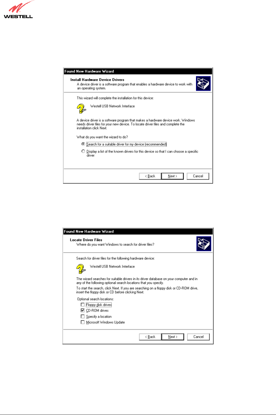
2. Windows 2000: The Install Hardware Device Drivers window appears. Select Search for a suitable driver
for my device (recommended). See Figure 23. Click Next.
Figure 23. Windows 2000
3. Windows 2000: The Locate Driver Files window appears. Select CD-ROM drives (Figure 24). Click Next.
Figure 24. Windows 2000
030-300432 Rev. A 33 December 2004
User Guide
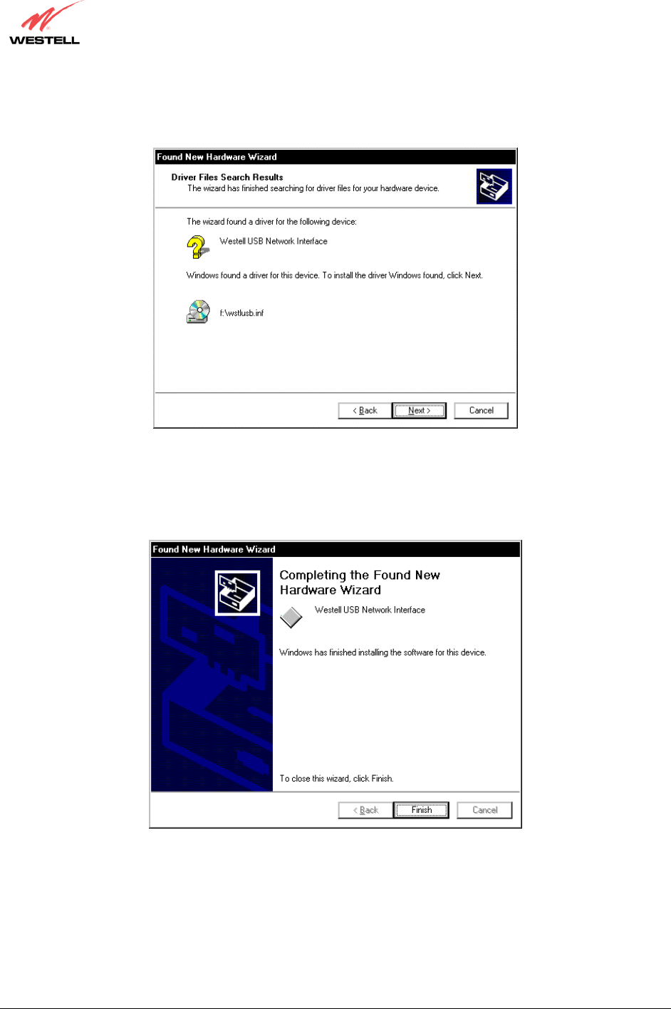
4. Windows 2000: The Driver Files Search Results window appears (Figure 25). Note: The drive “letter” may
vary. Click Next.
Figure 25. Windows 2000
5. Windows 2000: The window below confirms that the PC has finished loading the drivers (Figure 26). Click
Finish.
Figure 26. Windows 2000
030-300432 Rev. A 34 December 2004
User Guide
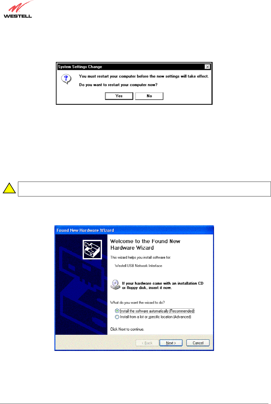
6. Windows 2000: When the System Settings Change screen appears, the USB drivers are installed properly
(Figure 27). Click Yes.
Figure 27. Windows 2000
Congratulations! You have completed the software installation for the USB drivers. After you have finished
installing the USB drivers, you must return to section 6.4.4 (Installation via USB) to complete the installation
instructions.
7.5 Installing the USB Driver for Windows XP
IMPORTANT: Confirm that the CD-ROM provided with the Router kit is inserted in the
appropriate drive before continuing this installation.
1. Windows XP: After you connect the Router to your PC, the following screen will appear. (Figure 28). Select
Install the software automatically (Recommended). Click Next.
Figure 28. Windows XP
!
030-300432 Rev. A 35 December 2004
User Guide
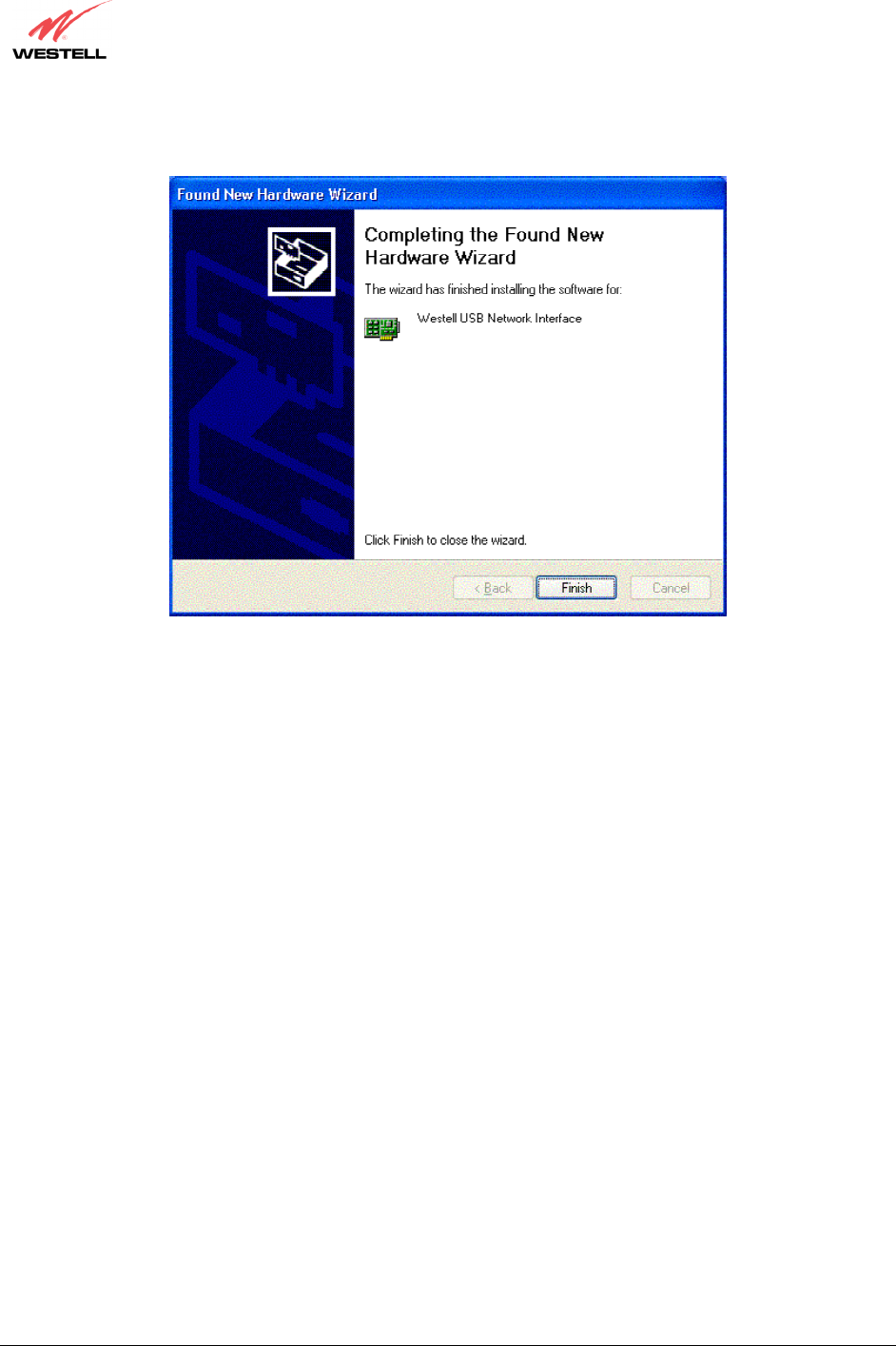
2. Windows XP: The window below confirms that the PC has finished loading the drivers (Figure 29). Click Finish.
Figure 29. Windows XP
Congratulations! You have completed the software installation for the USB drivers. After you have finished
installing the USB drivers, you must return to section 6.4.4 (Installation via USB) to complete the installation
instructions.
030-300432 Rev. A 36 December 2004
User Guide
8. CONFIGURING THE ROUTER FOR INTERNET CONNECTION
To browse the Internet using the Router, you must set up your account profile, confirm your DSL sync, and establish
a PPP session with your Internet Service Provider (ISP). Refer to the Internet service provider’s installation manual
to install the software required for your Internet connection.
NOTE: Internet service provider subscriber software and connection requirements may vary. Consult your Internet
service provider for installation instructions.
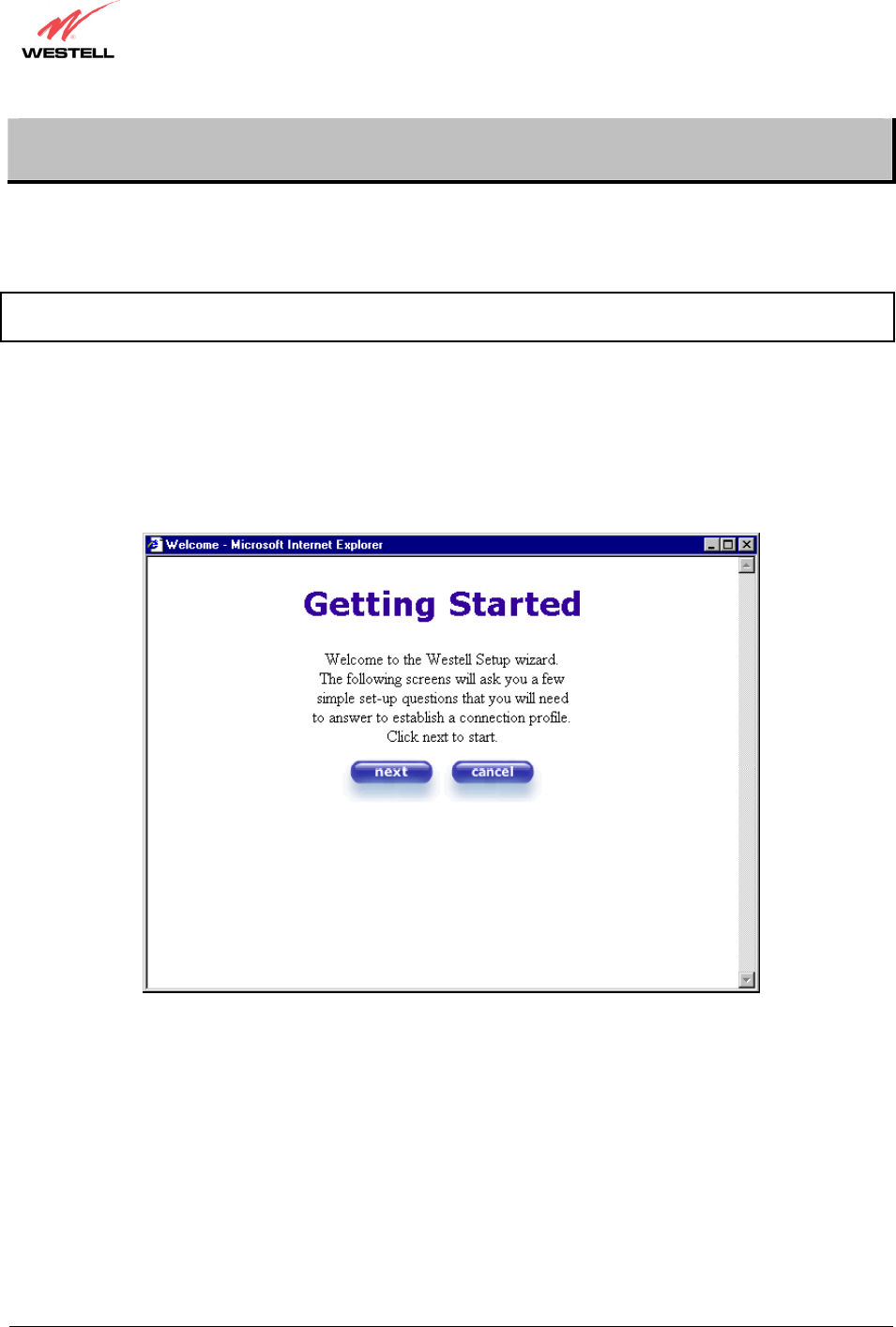
8.1 Setting Up an Account Profile
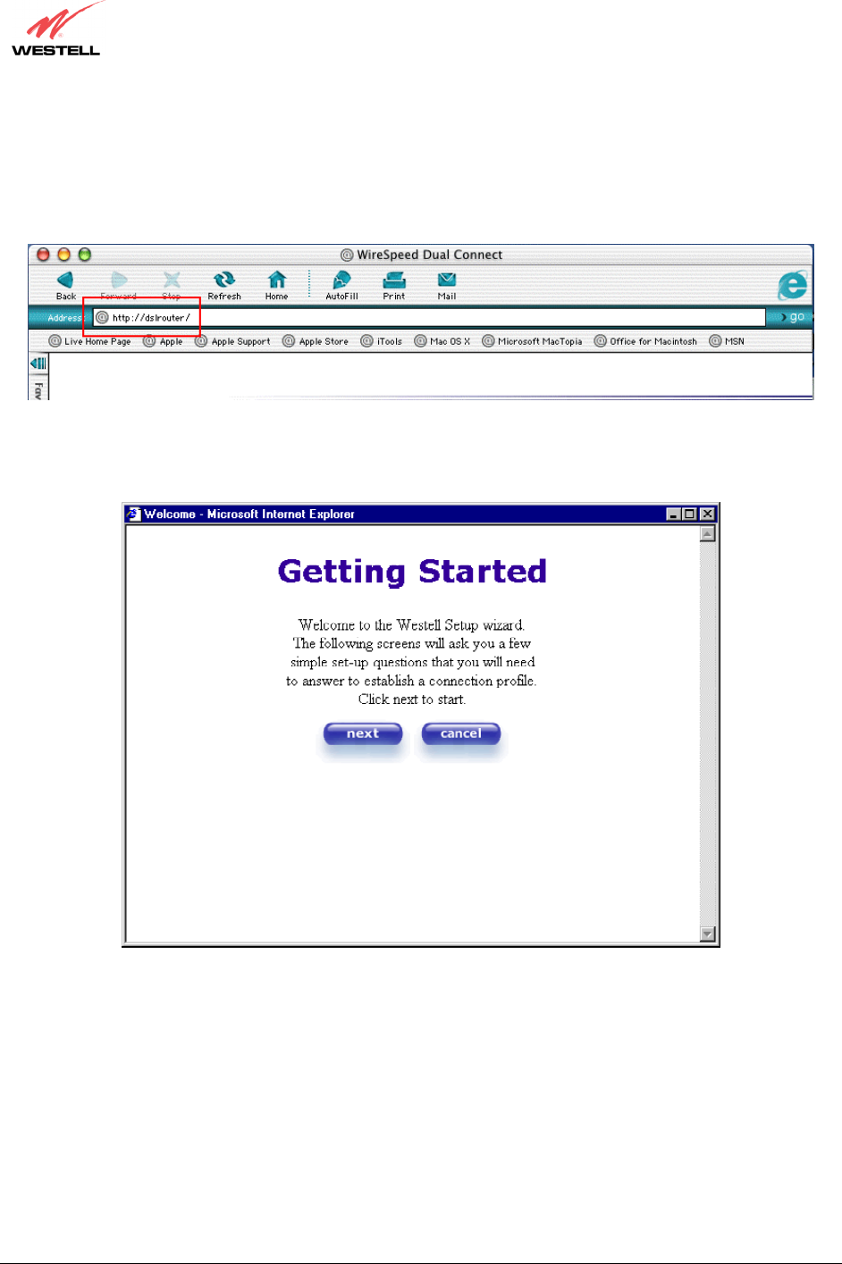
After connecting the Router, bring up your Web browser and type either http://dslrouter or http://192.168.1.1 in
the browser’s address window, and then press ‘Enter’ on your keyboard. The Getting Started screen will appear.
Click on next.
030-300432 Rev. A 37 December 2004
User Guide
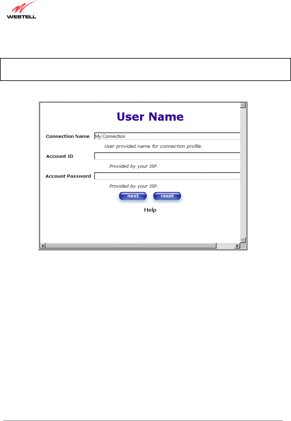
If you clicked next in the Getting Started screen, the following screen will be displayed. This screen will allow you
to set up your account profile.
NOTE: Before you set up your account profile, you must obtain your Account ID, Account Password, and VPI/VCI
values from your Internet service provider. You will use this information when you set up your account parameters. If
you are at a screen and need help, click the Help button to learn more about the functions in that screen.
Type in your account parameters. (Account parameters are required before connecting to the Internet.)
Account Parameters include:
● Connection Name-the Connection Name is a word or phrase that you use to identify your account.
(You may enter up 64 characters in this field.)
● Account ID-the Account ID is provided by your Internet Service Provider.
(You may enter up 255 characters in this field.)
● Account Password-the Account Password is provided by your Internet Service Provider.
(You may enter up 255 characters in this field.)
030-300432 Rev. A 38 December 2004
User Guide
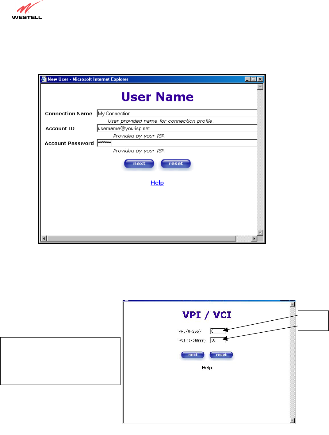
After you type your account parameters at the User Name screen, the Account ID will be displayed, however, the
Password will be masked for security, as shown below. Click next if you want your account parameters to take
effect. Click reset if you do not want the account parameters to take effect or if you want to retype the parameters.
Type the VPI and VCI values (0 for VPI and 35 for VCI default) you obtained from your Internet service provider.
The actual VPI/VCI values may vary according to your ISP. Click on next.
N
OTE: Depending on your Internet Service
Provider, the VPI/VCI screen may come
pre-configured and it will be displayed here.
In this case, you should not change any
values in this screen. Click on next to go to
the PROTOCOL screen.
VPI = 0
VCI = 35
030-300432 Rev. A 39 December 2004
User Guide
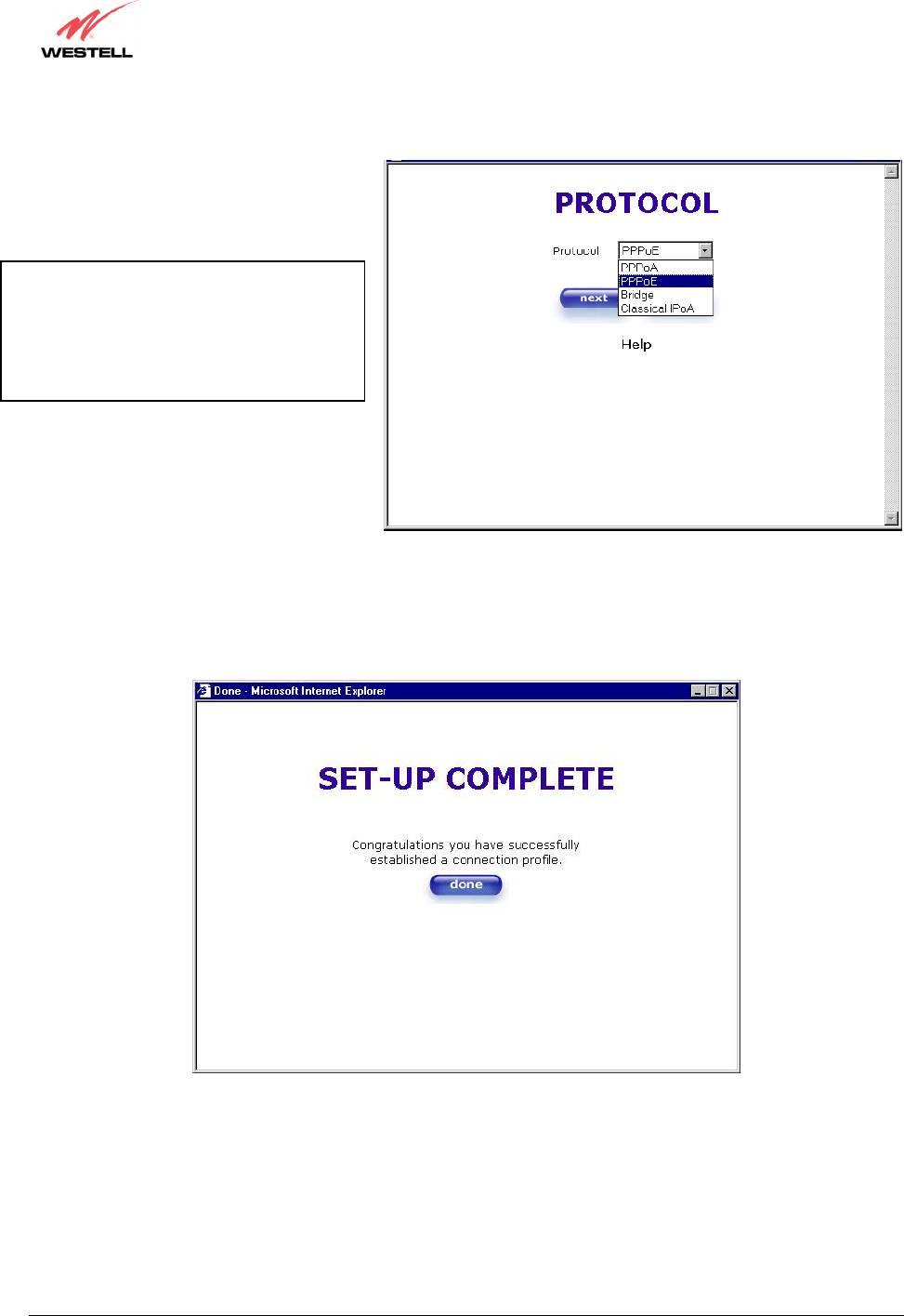
Select the Protocol type that you obtained from your Internet service provider. Click on next.
When the SET-UP COMPLETE screen appears, you have successfully completed your Account Profile setup.
Click done.
N
OTE: Depending on your Internet Service
Provider, the PROTOCOL screen may
come pre-configured and it will be displayed
here. In this case, you will need to click on
next to go to the SET-UP COMPLETE
screen.
030-300432 Rev. A 40 December 2004
User Guide
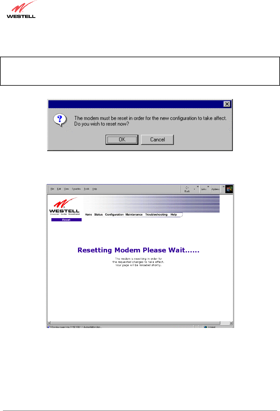
If you changed the VPI/VCI settings and clicked done in the SET-UP COMPLETE screen, the following pop-up
screen will appear. Click OK.
NOTE: The following pop-up will appear only if you have changed the VPI, VCI, or Protocol values in the
preceding screens. If you did not change any of these values, this pop-up screen will not appear and the Router will
not be reset. If your Router’s connection setting is set to “Always On” and you have changes any of these values, the
Router will reset automatically. For instructions on editing your connection settings, see section 11.2.
If you clicked OK in the pop-up, the following screen will be displayed. The Router will be reset and the new
configuration will take effect. Next, proceed to section 8.2 to confirm your DSL sync.
030-300432 Rev. A 41 December 2004
User Guide
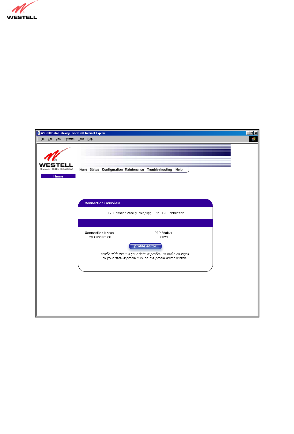
8.2 Confirming a DSL Sync
Remember, you must have active DSL service before the Router can synchronize with your ISP’s equipment. To
determine if the Router has a DSL sync, view the DSL Connection Rate in the Connection Overview section (see the
following Home page). If the status reads No DSL Connection, check the DSL physical connection, explained in
section 6 (INSTALLING THE HARDWARE) of this User Guide.
NOTE: If no DSL sync is established, the connection button will not be displayed in the following screen. To
determine if the DSL sync is established, check the Router’s DSL LED. If the DSL LED is not solid green, you do
not have a DSL sync established. Contact your ISP for further instructions.
030-300432 Rev. A 42 December 2004
User Guide
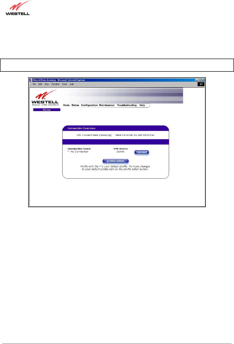
The following screen shows the DSL connection rate with values that indicate a successful DSL SYNC has been
established. The connection rate values represent the transmission speed of your DSL line. (The Router may take
time to report these values.) Click the Connect button to establish a PPP session.
NOTE: The Router will handle transmission rates up to 8 Mbps. Your actual DSL rates may vary depending on your
Internet service provider.
030-300432 Rev. A 43 December 2004
User Guide
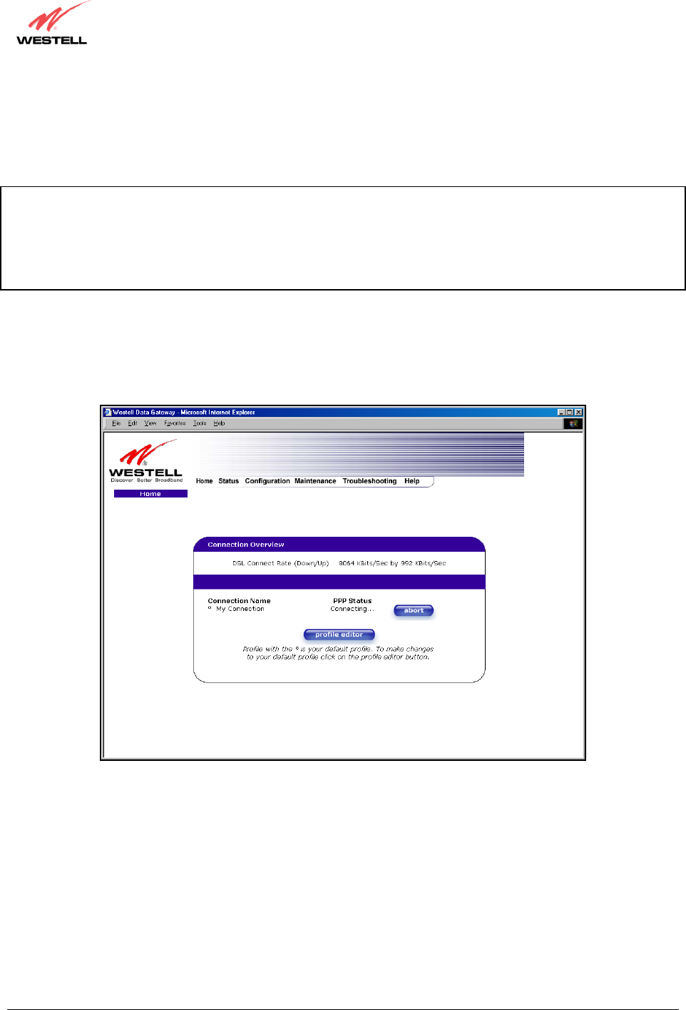
8.3 Establishing a PPP Session
View the PPP Status at the Home page. If the PPP Status displays DOWN, click the Connect button to establish a
PPP session.
NOTE: Whenever the PPP Status displays DOWN, you do not have a PPP session established. If your Router’s
connection setting is set to “Always On” or “On Demand,” after a brief delay, the PPP session will be established
automatically and the PPP Status will display UP. If the connection setting is set to “Manual,” you must click on the
Connect button to establish a PPP session. Once the PPP session has been established (PPP Status displays UP),
you may proceed with your Router’s configuration. Section 11.2 provides instructions on editing the connection
settings. (Refer to the ‘Edit My Connection’ screen.) The Router’s factory default connection setting is “Manual.”
If you click the Connect button, the following screen will appear briefly. The PPP Status in the Connection
Overview window allows you to view the state of your ISP connection. When the PPP Status displays
Connecting…, this means that you are establishing a PPP session.
030-300432 Rev. A 44 December 2004
User Guide
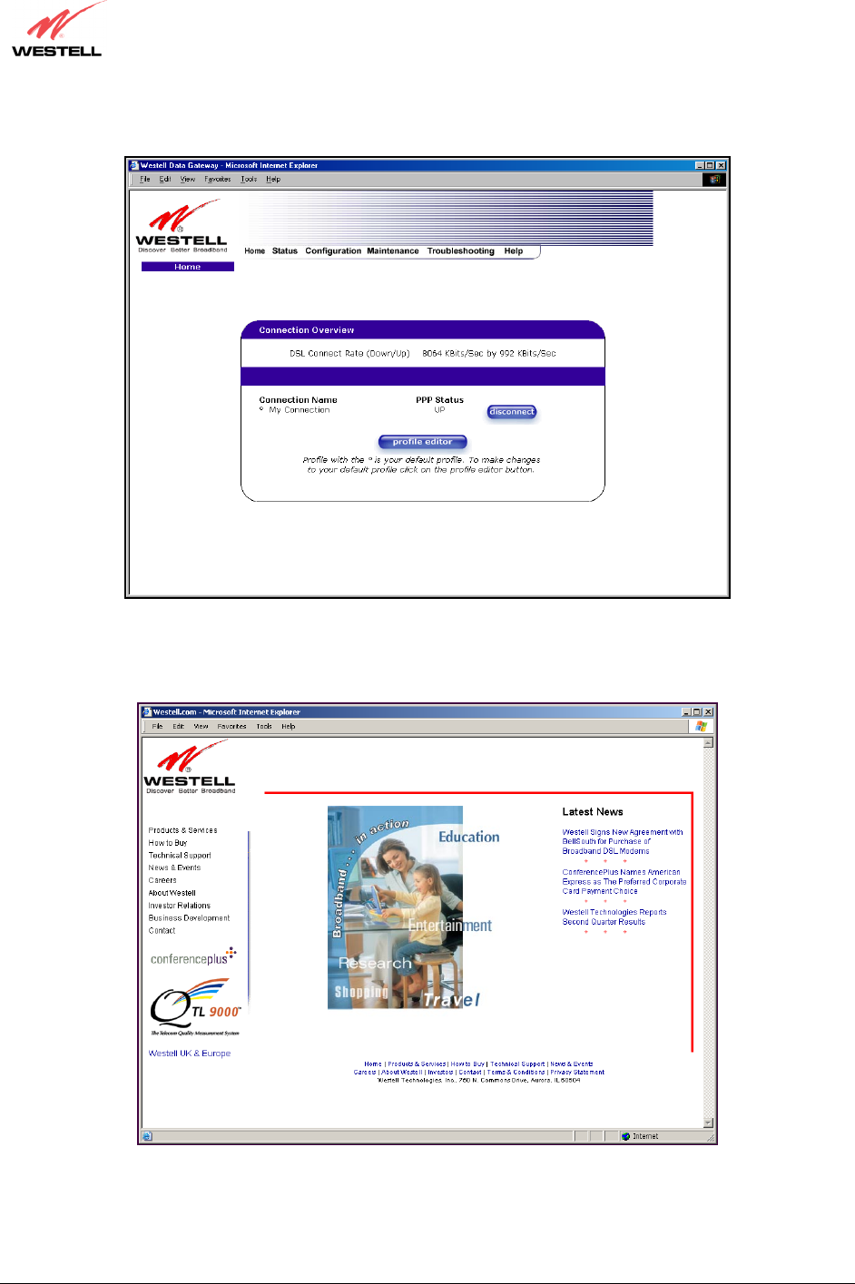
After a PPP session has been established, the PPP Status will display UP, and you may now browse the Internet.
For example, to visit Westell’s home page, type http://www.westell.com in your browser’s address window, and
then press ‘Enter’ on your keyboard.
When you are ready to return to the Router’s interface, type http://192.168.1.1 in your browser’s address window,
and then press ‘Enter’ on your keyboard.
030-300432 Rev. A 45 December 2004
User Guide
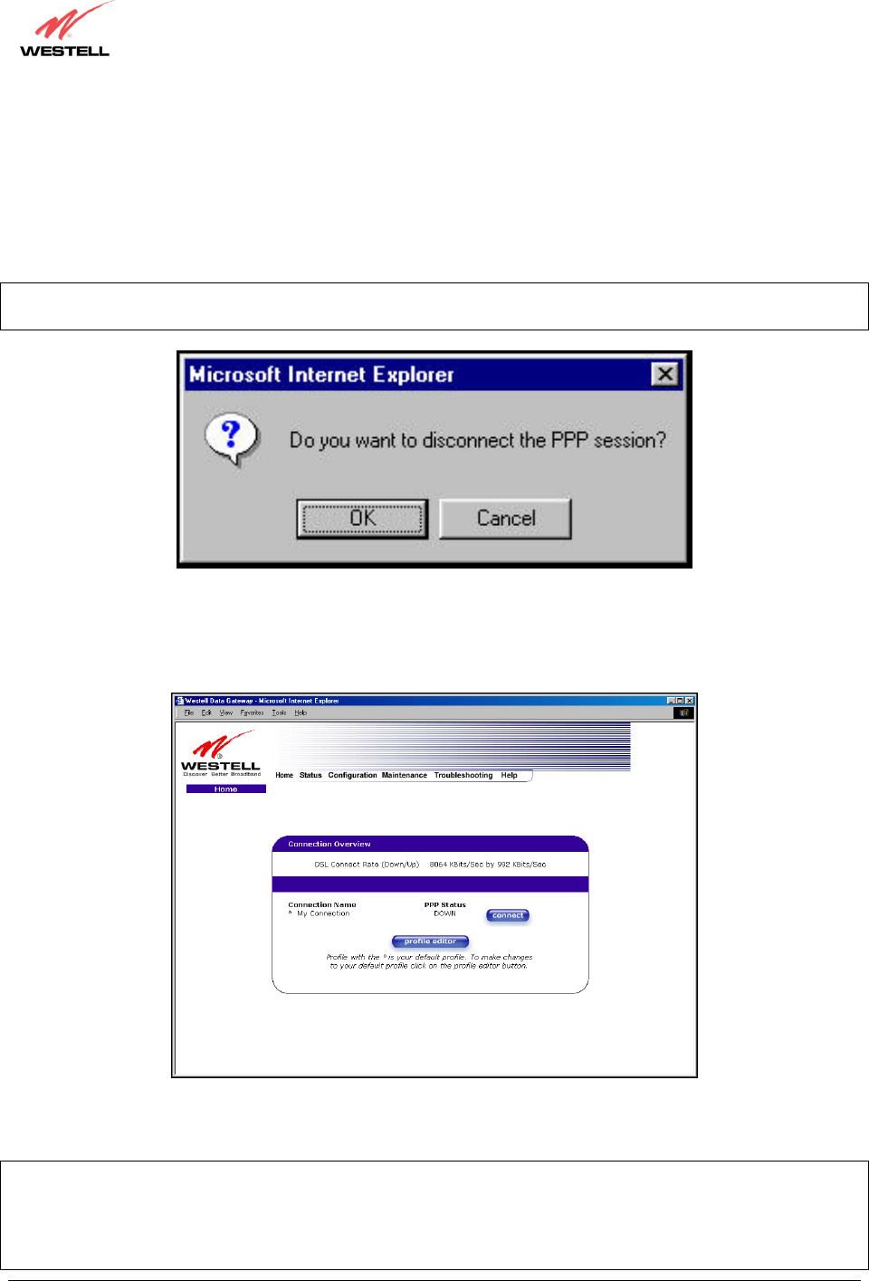
8.4 Disconnecting a PPP Session
If you have finished browsing the Internet and want to disconnect from your Internet service provider, click on the
Disconnect button in the Connection Overview screen (the preceding screen). The following pop-up screen will
appear. Click on OK to disconnect the PPP session.
Warning: If you disconnect the PPP session, this will disconnect the Router from the Internet, and all users will be
disconnected until the PPP session is re-established.
If you clicked the Disconnect button in the preceding Connection Overview screen, the PPP Status should display
DOWN. This means that you no longer have a PPP session (no IP connection to your Internet service provider).
However, your DSL session will not be affected. When you are ready to end your DSL session, simply power down
the Router via the power switch on the Router’s rear panel.
When you are ready to establish a PPP session, click on the connect button. (If you powered down the Router, you
must first power up the Router and log on to your account profile before you establish a PPP session.)
NOTE: When you are ready to exit the Router’s interface, click the X (close) in the upper-right corner of the
window. Closing the window will not affect your PPP Status (your PPP session will not be disconnected). You must
click on the disconnect button to disconnect your PPP session. When you are ready to restore this interface, you
must launch your Internet browser and type http://dslrouter/ or type http://192.168.1.1/ in the browser’s address
window and press ‘Enter’ on your keyboard.
030-300432 Rev. A 46 December 2004
User Guide
9. SETTING UP MACINTOSH OS X
This section provides instructions on how to use Macintosh Operating System 10 with the Router. Follow the
instructions in this section to create a new network configuration for Macintosh OS X.
NOTE: Macintosh computers must use the Modem Ethernet installation. Refer to section 6 (INSTALLING
THE HARDWARE).
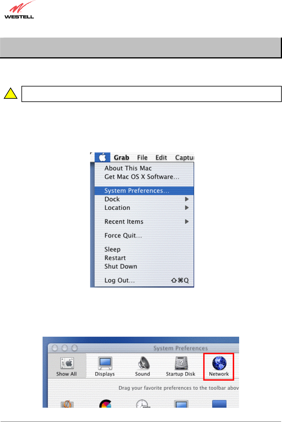
Open the System Preference Screen
After you have connected the Westell Router to the Ethernet port of your Macintosh, the screen below will appear.
Click on the “Apple” icon in the upper-right corner of the screen and select System Preferences.
Choose the Network Preferences
After selecting System Preferences…, from the previous screen, the System Preferences screen will be displayed.
From the System Preferences screen, click on the Network icon.
!
030-300432 Rev. A 47 December 2004
User Guide
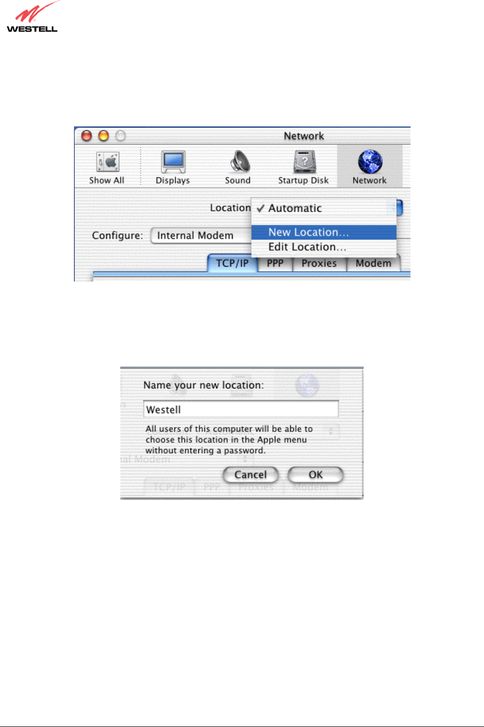
Create a New Location
After selecting the Network icon at the System Preferences screen, the Network screen will be displayed. Select
New Location from the Location field.
Name the New Location
After selecting New Location from the Network screen, the following screen will be displayed. In the field labeled
Name your new location:, change the text from “Untitled” to “Westell.” Click OK.
030-300432 Rev. A 48 December 2004
User Guide
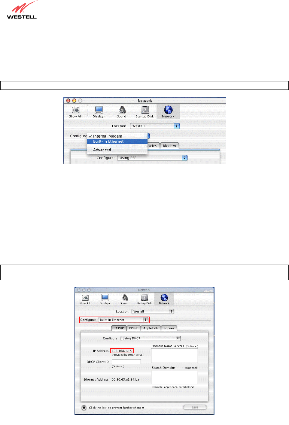
Select the Ethernet Configuration
After clicking on OK in the preceding screen, the Network screen will be displayed. The Network screen shows the
settings for the newly created location. From the Configure field in the Network screen, select Built-in Ethernet.
Click on Save.
NOTE: Default settings for the Built-in Ethernet configuration are sufficient to operate the Router.
Check the IP Connection
To verify that the computer is communicating with the Router, follow the instructions below.
1. Go to the “Apple” icon in the upper-right corner of the screen and select System Preferences.
2. From the System Preferences screen, click on the Network icon. The Network screen will be displayed.
3. From the Configure field in the Network screen, select Built-in Ethernet.
4. View the IP address field. An IP address that begins with 192.168.1 should be displayed.
NOTE: The DHCP server provides this IP address. If this IP address is not displayed, check the Router’s wiring
connection to the PC. If necessary, refer to section 5 for hardware installation instructions.
030-300432 Rev. A 49 December 2004
User Guide
Create a User Account
In the address window of your Internet Explorer web browser, type http://dslrouter/, and then press ‘Enter’ on your
keyboard.
The Getting Started screen will be displayed. You may now begin your Account Setup. Refer to section 8 of this
User Guide to configure your Westell Router for Internet connection.

030-300432 Rev. A 50 December 2004
User Guide
The following sections explain the advanced features of your Westell Router.
[This Page Intentionally Left Blank]

030-300432 Rev. A 51 December 2004
User Guide
10. SETTING UP ADVANCED CONFIGURATION
Advanced Configuration instructions are explained in Section 11 through Section 17. If you want to set up advanced
features for the Router, follow the instructions provided in sections 11 through 17.
STOP! The following sections assume that you have active DSL and Internet service.
The Router allows you to make changes to advanced features of your Router such as account profiles, routing
configurations, and firewall settings. The following sections explain each feature and show you how to make
changes to the Router’s settings. A menu is displayed at the top of each screen and will allow you to navigate you to
the various configuration options of your Router. If you are at a screen and need help, click on the Help button to
learn more about that screen.
Please note that for Models 328W10 and 328W11, the menu options displayed will vary according to the WAN
configuration you have chosen to use, DSLATM PORT or ETHERNET PORT1. However, all menu options are
displayed when the Router is enabled for DSLATM PORT. Instructions on enabling and disabling DSLATM PORT
and ETHERNET PORT 1 are explained in section 13.6.2 VC Configuration. This document was created with the
Router’s DSLATM PORT enabled. The sections explained throughout this document will indicate when a menu
item is unavailable.
030-300432 Rev. A 52 December 2004
User Guide
11. HOME
As you navigate through the various screens of the Router, the name of the active page you have selected will appear
in the upper-left corner of the screen, as shown below. Please note that the actual values may differ from the values
displayed in the screens.
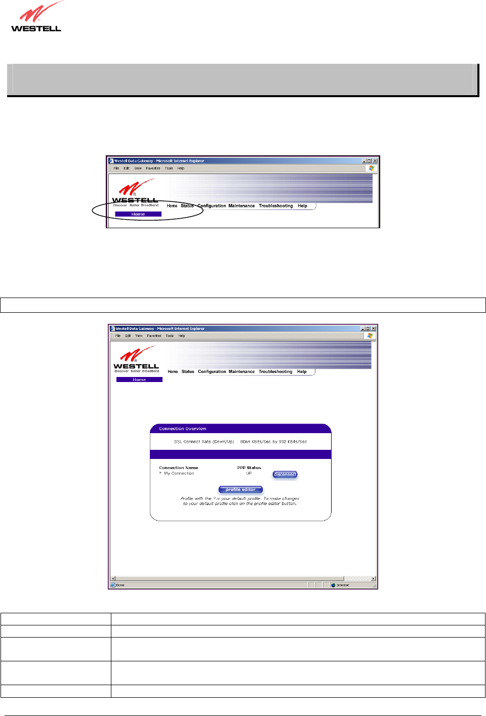
If you have set up your account profile and established your PPP session as discussed in section 8, the following
settings will be displayed when you click on your Home page. Click on profile editor to edit your connection
profile.
NOTE: If you have created multiple account profiles, select the option button for the active account profile.
Connection Overview Displays your DSL connection rate.
Connection Name This Connection Name is from the connection profile that you established in section 8.
PPP Status UP = PPP session established
DOWN = No PPP session established.
Connect/Disconnect CONNECT = Establish a PPP session
DISCONNECT = Disconnect a PPP session
Profile Editor This allows you to make changes to the profile that you created in section 8.
030-300432 Rev. A 53 December 2004
User Guide
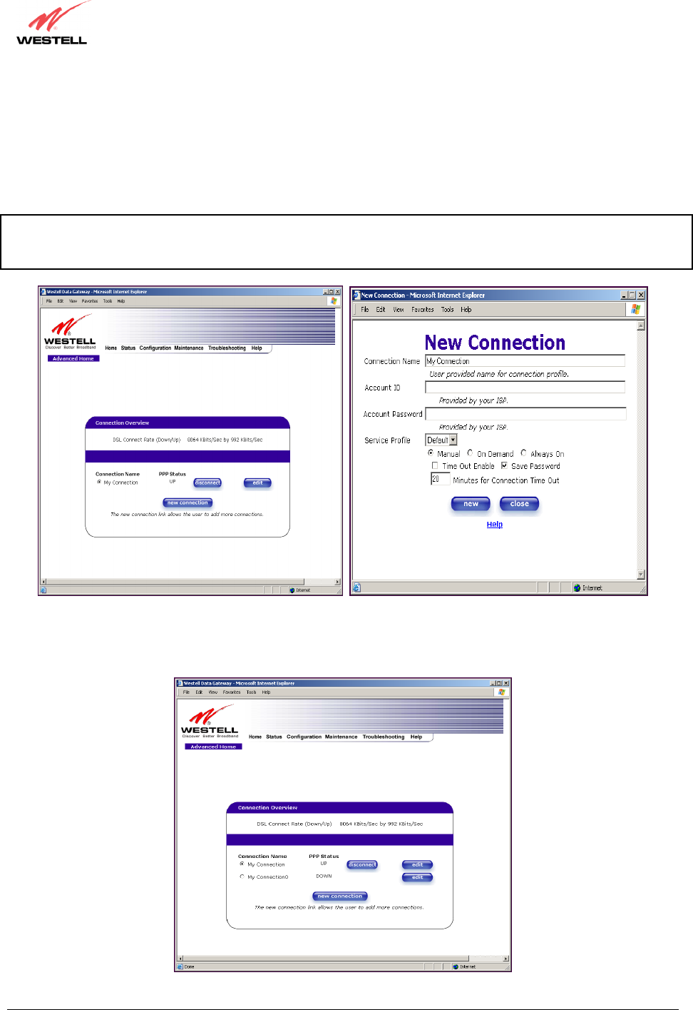
11.1 Adding Account Profiles
If you select the Profile Editor button from your Home page, the Advanced Home screen will appear, as shown
below. Click on the new connection button in the Advanced Home screen. The New Connection screen will
appear. Enter your account profile information and click on New. Next, click on OK in the pop-up screen to save
your new connection. If you do not want to add a connection profile, click on Close in the New Connection screen.
NOTE: NAT Profiles allow you to create specific service settings. A NAT Profile may be associated with a certain
connection setting, or NAT services. This allows you to customize the profile for specific users. You may store up to
eight unique user profiles in your Router. Details on the New Connection screen are located at the end of this section.
If you clicked OK in the pop-up screen, the following screen will be displayed. This screen enables you to edit a
connection profile. Select a profile name from the Connection Name field, and click the adjacent edit button.
030-300432 Rev. A 54 December 2004
User Guide
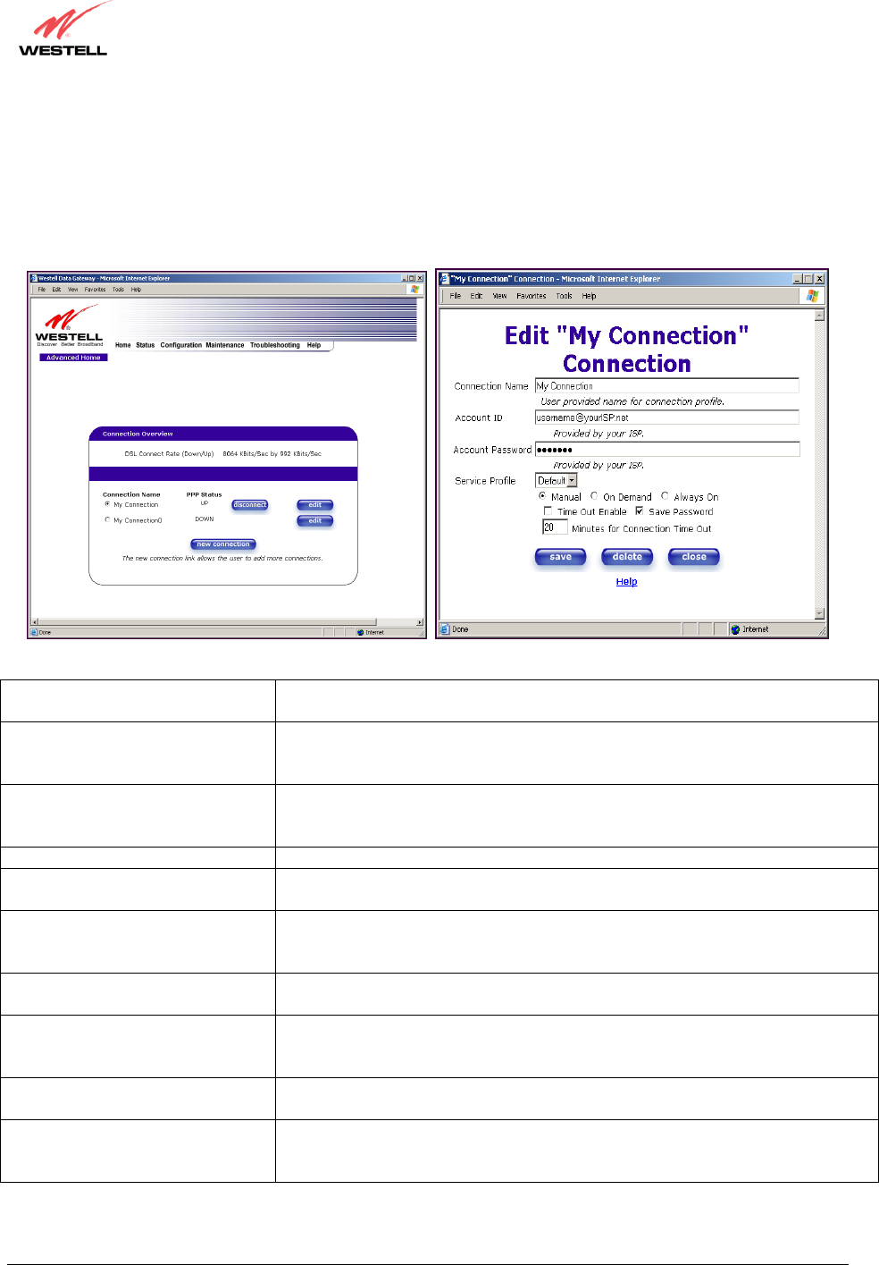
11.2 Editing Account Profiles
If you clicked Edit in the preceding screen, the Edit “My Connection” screen will appear. To change your existing
connection profile, follow the steps in the Edit “My Connection” screen. When you have finished editing your
profile, click save and then click OK in the pop-up screen. Click delete if you want to delete your connection
profile. Click close if you do not want to edit your connection profile.
Connection Name This field allows you to enter a new connection name of your choice (up to 64
characters).
Account ID The account ID that you used in section 8 if you are connecting to the same
Service Provider. If you have multiple Service Providers, you can enter this
information at this time.
Account Password The account password that you used in section 8 if you are connecting to the
same Service Provider. If you have multiple Service Providers, you can enter this
information at this time.
Service Profile Westell recommends that you use the Default parameter.
Manual Factory default = MANUAL
Selecting this feature allows you to manually establish your PPP session.
On Demand Selecting this feature allows the Router to automatically re-establish your PPP
session on demand anytime your PC requests Internet activity (for example,
browsing the Internet, email, etc.). When you have traffic, it may cause a delay.
Always On Selecting this feature allows the Router to automatically establish a PPP session
when you log on, or if the PPP session goes down.
Time Out Enable Factory Default = DISABLED
Selecting this feature allows you to enable the timeout parameter of your PPP
session, which is set to a factory default of 20 minutes.
Save Password Selecting this feature allows you to save the password for your new connection
profile in the Router so that you will not have to re-enter it in case of a re-boot.
Minutes for Connection Time Out This option allows you to specify the number of minutes that you want a PPP
session to stay active before it is disconnected due to inactivity. (This feature
works if you have selected the Time Out Enable feature explained above.)
030-300432 Rev. A 55 December 2004
User Guide
12. STATUS
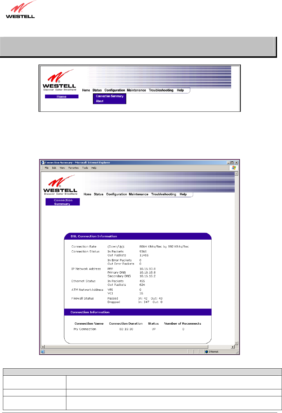
12.1 Connection Summary
The following settings will be displayed if you select Connection Summary from the Status menu.
DSL Connection Information
Connection Rate This field will indicate if you have a DSL signal and the DSL rate at which you are
connected.
Connection Status This field will show how much information was received (IN) or sent (OUT) in packets.
IP Network Address PPP = An IP address identifies your device on the Internet
Primary DNS = Provided by your Service Provider
Note: The actual values may differ from the values displayed in this screen.
030-300432 Rev. A 56 December 2004
User Guide
Secondary DNS = Provided by your Service Provider
Ethernet Status This field will display your Ethernet information that was received (IN) or sent (OUT) in
packets on your Ethernet port.
ATM Network Address This field will display your VPI and VCI values, which are provided by your ISP.
Firewall Status This field will display your firewall traffic in packets.
Passed: Monitors information traffic that was successfully received (IN) or transmitted
(OUT) in packets.
Dropped: Monitors information traffic that was not successfully received (IN) or
transmitted (OUT) due to your firewall settings.
PPP Connection Information
Connection Name This is from the connection profile that you established in section 8.
Connection Duration This field will display how long your PPP session has been connected.
Status This field will display the status of your PPP session.
UP=Connected
DOWN=Disconnected
Number of Reconnects This field will display the number of attempts that were made to establish a PPP session.
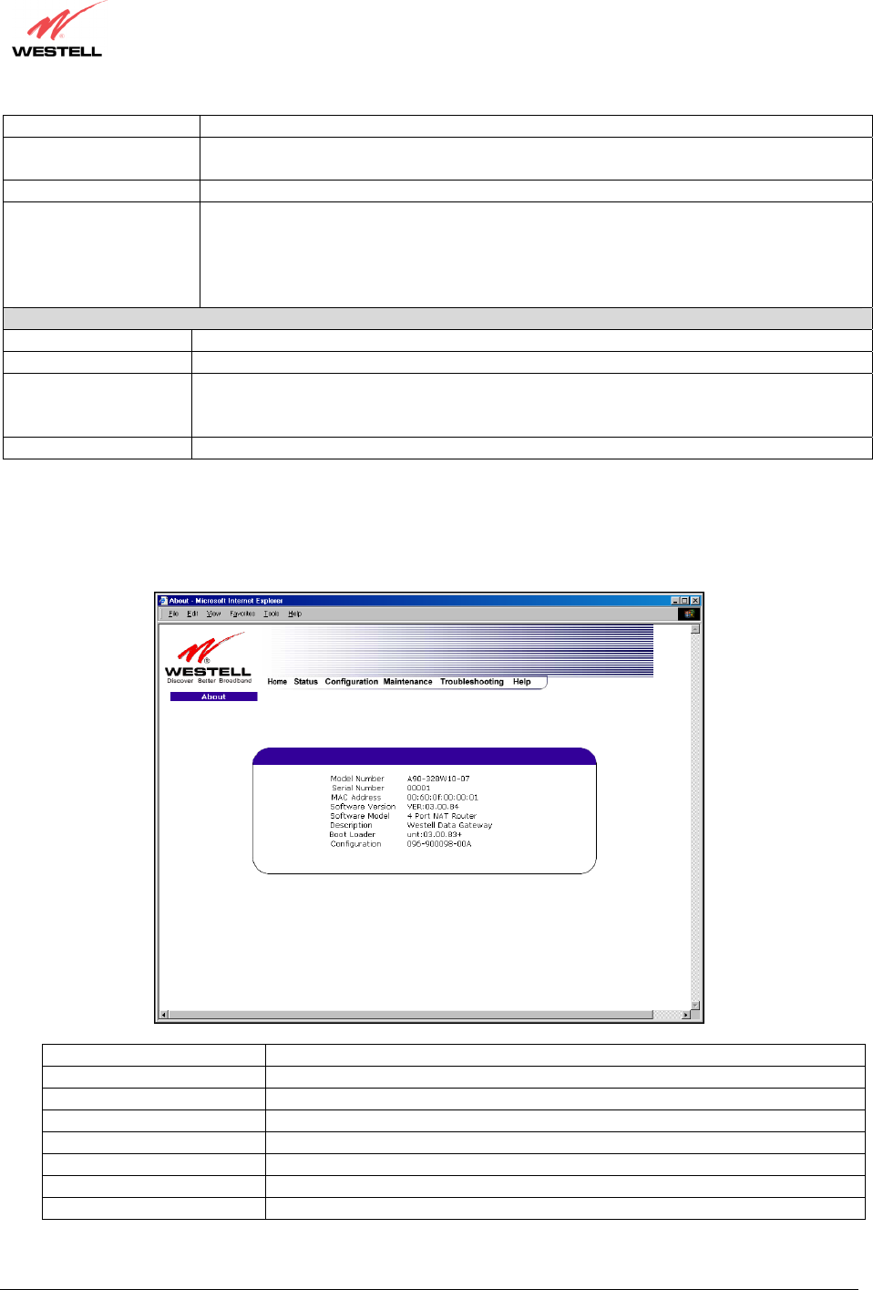
12.2 About
The following settings will be displayed if you select About from the Status menu.
Model Number The Router manufacturer’s model number.
Serial Number The Router manufacturer’s serial number.
MAC Address Media Access Controller (MAC) i.e., hardware address of this device.
Software Version Version of Application Software.
Software Model The Router application type.
Description Product description.
Boot Loader Version of boot loader software
Configuration Westell proprietary configuration of this device.
Note: The actual values ma
y
differ from the values dis
p
la
y
ed in this screen.
030-300432 Rev. A 57 December 2004
User Guide
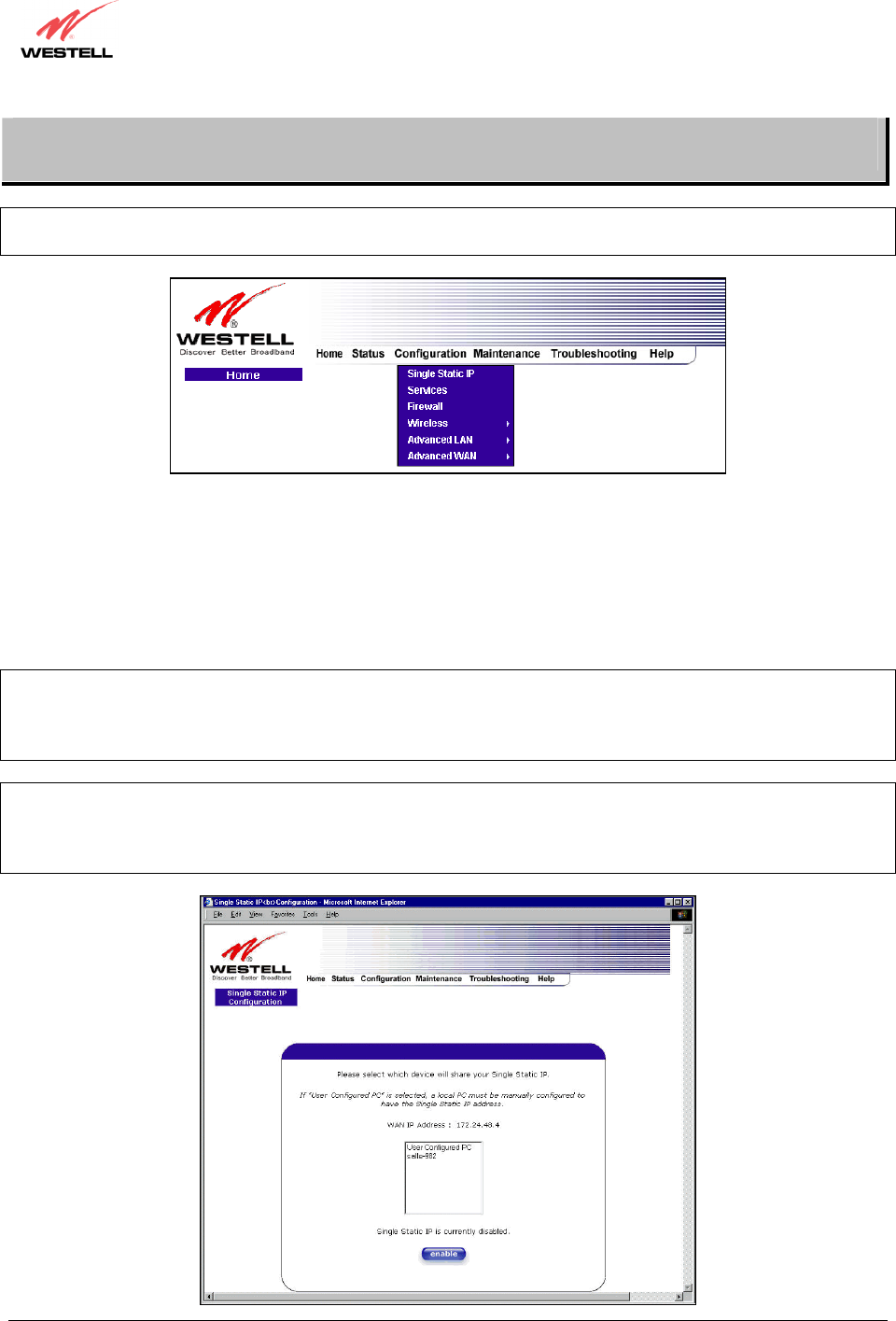
13. CONFIGURATION
NOTE: If you are using Model 7400 or 7401, the “Wireless” menu options will not be displayed in the
Configuration menu.
13.1 Single Static IP – Single IP Address PassThrough
The following settings will be displayed if you select Single Static IP from the Configuration menu. The Single
Static IP Configuration screen allows you to select the device on your LAN that will share your Single Static IP.
Before you begin this section, configure your PC settings to obtain an IP address from your Router automatically.
(Refer to your Windows Help screen for instructions.)
NOTE: Single Static IP (SSI) allows the user to share the WAN assigned IP address with one device on the LAN.
By doing this, the device with the SSI becomes visible on the Internet. Network Address Translation (NAT) and
Firewall rules do not apply to the device configured for SSI. If you are using Bridge (Routed Bridge) protocol,
Single Static IP configuration will not be available.
STOP: Static NAT must be disabled before you can enable Single Static IP. To disable Static NAT, select Services
from the Configuration menu. Next, click on the static NAT button. Select the device from the Static NAT Device
drop-down menu and click on disable. Return to Single Static IP Configuration by selecting Single Static IP
Configuration from the Configuration menu.
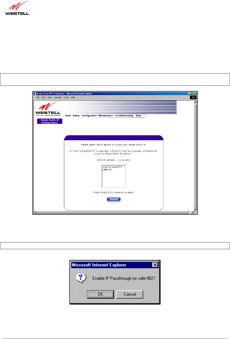
030-300432 Rev. A 58 December 2004
User Guide
13.1.1 Enabling Single Static IP – Single IP Address PassThrough
(Applicable for PPPoE Connections Only)
To enable Single Static IP, select a device that will share your Single Static IP from the options listed in the window.
Click on enable.
NOTE: The Single Static IP Configuration screen allows you to select the device on your LAN that will share your
Single Static IP.
If you select a device and clicked on enable, the following pop-up screen will appear. Click on OK to enable this
device for Single Static IP. Click on Cancel if you do not want to enable Single Static IP.
NOTE: The actual device name may differ from the name displayed in this screen.
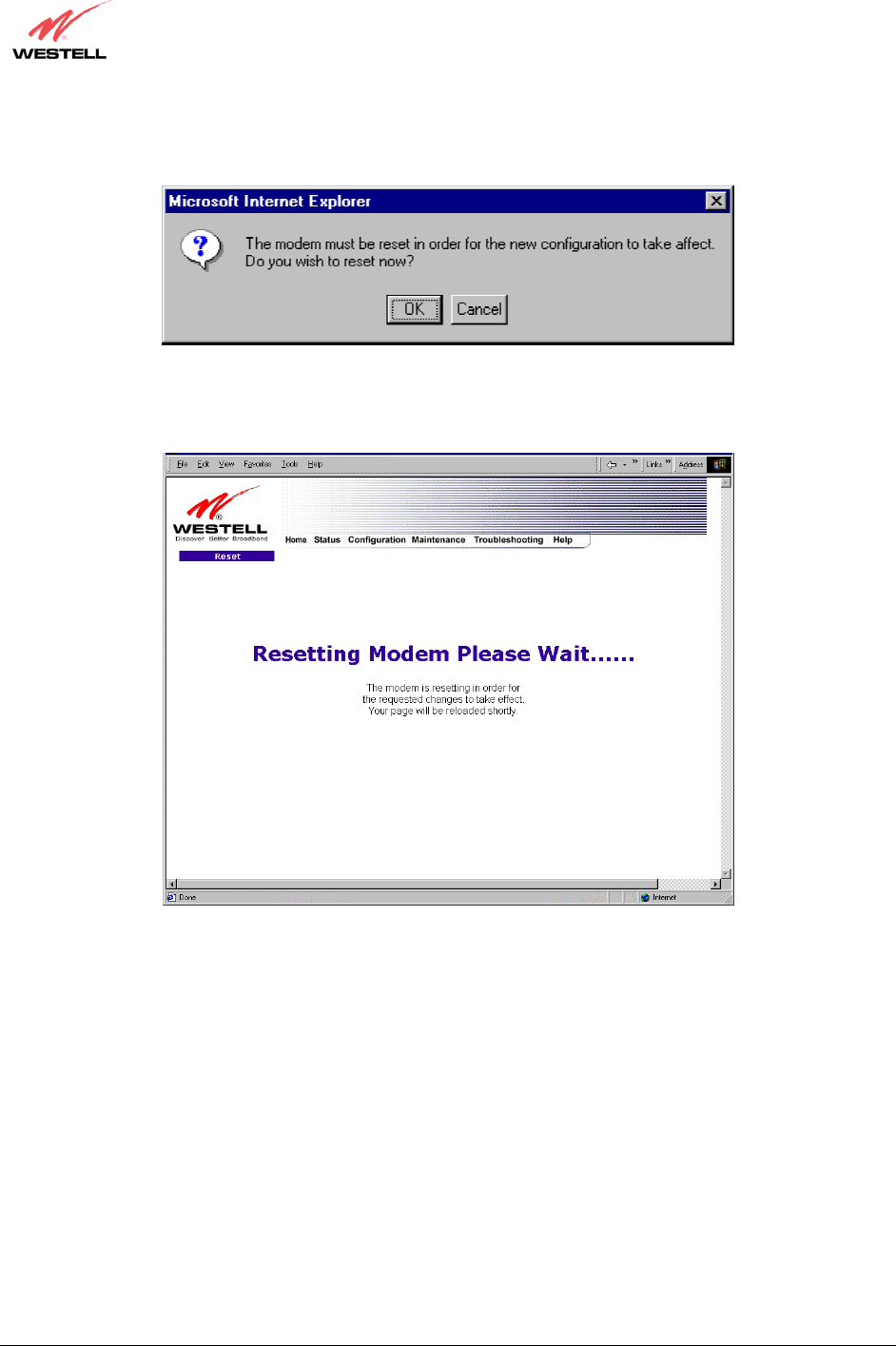
030-300432 Rev. A 59 December 2004
User Guide
If you clicked OK in the preceding pop-up screen, the following pop-up screen will appear. The Router must be
reset to allow the new configuration to take effect. Click on OK.
If you clicked OK in the preceding screen, the following screen will be displayed. The Router will be reset and the
new configuration will take effect.
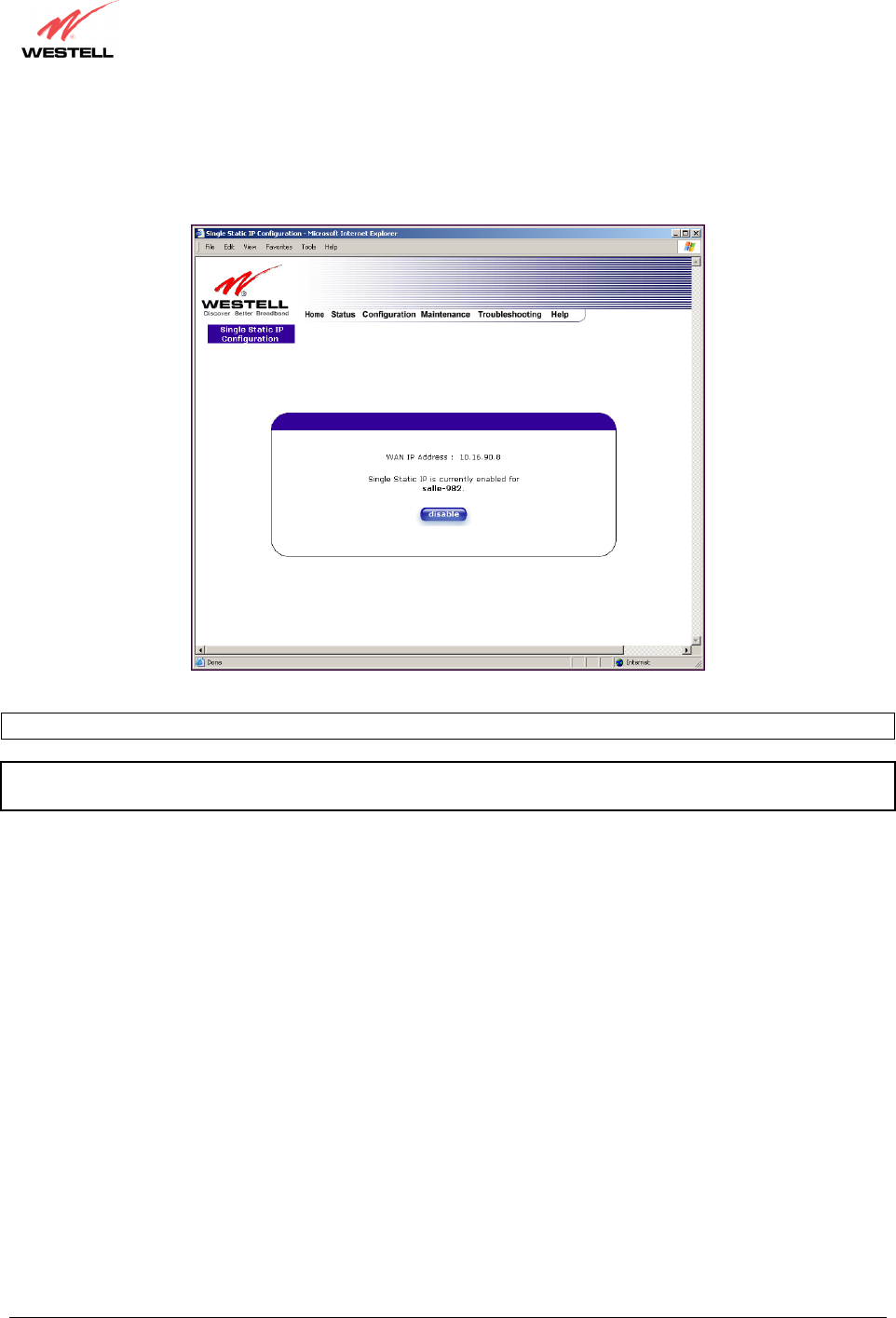
030-300432 Rev. A 60 December 2004
User Guide
After a brief delay, the home page will be displayed. Confirm that you have a DSL sync and that your PPP session
displays UP. (Click on the connect button to establish a PPP session). Next, select Single Static IP from the
Configuration menu to confirm that Single Static IP is enabled, as shown in the following screen.
STOP! After you enable Single Static IP, you must reboot your computer.
NOTE: If you chose to enable User Configured PC, wait for the Router to reset and then manually enter the WAN
IP, Gateway, and Subnet mask addresses you obtained from your Internet service provider into a PC.