Whirlpool Europe S r l COMBOEMS00 BUILT-IN MICROWAVE OVEN User Manual II
Whirlpool Europe S.r.l. BUILT-IN MICROWAVE OVEN Users Manual II
Contents
Users Manual II
If oven does not operate:
Check that circuit breaker is not tripped or
house fuse blown.
See Use and Care Guide for troubleshooting list.
If you need assistance:
If you have questions about operating, cleaning or
maintaining your oven:
Refer to Use and Care Guide.
Call the Consumer Assistance Center: Check
your Use and Care Guide for a toll-free
number to call or call the dealer from whom you
purchased this appliance. The dealer is listed in
the Yellow Pages of your phone directory under
“Appliances — Household — Major — Service
and Repair.”
Part No. 8300653
© 2001 Printed in U.S.A.
Quick Reference
Table of Contents:
Pages
Product dimensions
Cutout dimensions
Before you start
Electrical requirements
Installation steps
If you need assistance:
Check your Use and Care Guide for a toll-free number to call or call
the dealer from whom you purchased this appliance. The dealer is
listed in the Yellow Pages of your phone directory under
“Appliances — Household — Major — Service and Repair.”
Call when you:
Have questions about built-in oven installation or operation.
Need to obtain the name and number of an authorized service
company.
When you call, you will need:
The built-in oven model number.
The built-in oven serial number.
Both numbers are listed on the model/serial rating plate, located on
the microwave oven frame.
1
1
1
2
23
IMPORTANT:
Read and save these instructions.
Installation Instructions
IMPORTANT:
Installer: Leave Installation Instructions with the homeowner.
Homeowner: Keep Installation Instructions for future reference.
Save Installation Instructions for local electrical inspector's use.
Part No.
8300653
27" and 30" Electric
Built-in Microwave/
Oven Combination
If you need service:
Maintain the quality built into your built-in oven by
calling an authorized service company.
To obtain the name and number of an authorized
service company:
Contact the dealer from whom you purchased
your built-in oven; or
Look in the Yellow Pages of your telephone
directory under “Appliances — Household —
Major — Service and Repair” for an authorized
service company; or
Call the Consumer Assistance Center. The toll-
free number is listed in your Use and Care Guide.
When you call, you will need:
The built-in oven model number.
The built-in oven serial number.
Both numbers are listed on the model/serial rating
plate, located on the microwave oven frame.
Page 1
4 screws
Phillips screwdriver
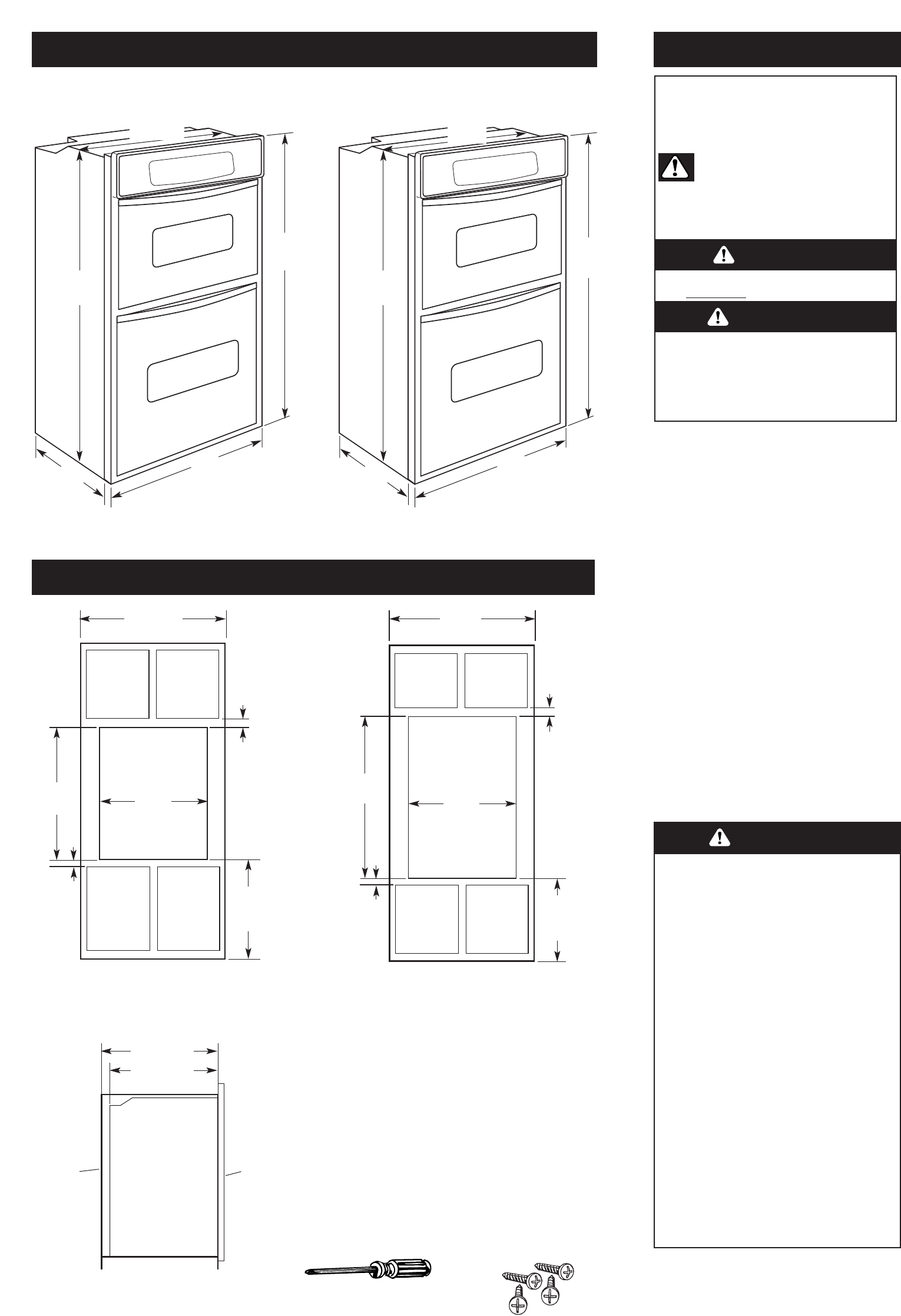
Product dimensions
Cutout dimensions
Before you start...
41"
recessed
height
42-7/16"
overall
height
25-3/8
recessed
width
23" max.
recessed
depth
27” oven
41"
recessed
height
42-7/16"
overall
height
28-3/8"
recessed
width
23" max.
recessed
depth
30” oven
30" min.
cabinet
1" top
of cutout
to bottom
of upper
cabinet door
27" min.
cabinet width
28-1/2"
cutout
width
25-1/2"
cutout
width
41-1/4"
cutout
height
19-1/4"
bottom
of cutout
to floor
1-1/2" min.
bottom of
cutout to
top of
cabinet
door
1" top of cutout
to bottom of
upper cabinet
door
1-1/2"
min.
bottom of
cutout to
top of
cabinet
door
19-1/4"
bottom of
cutout to
floor
30" oven
Cabinet side view
27" oven
41-1/4"
cutout
height
23-1/4" min.
cutout depth
23" recessed
oven depth
recessed
oven
cabinet oven
front
Important: Observe all governing codes
and ordinances.
Proper installation is your responsibility.
Have a qualified technician install this oven.
Oven location should be away from strong draft
areas, such as windows, doors and strong
heating vents.
Cabinet opening dimensions that are shown
must be used. Given dimensions provide
minimum clearance.
Recessed installation area must provide
complete enclosure around the recessed portion
of the oven.
Electrical ground is required. See “Electrical
requirements.”
Electrical supply junction box should be located
3 inches maximum below the support surface
when oven is installed in a wall cabinet. Cutout
for wiring should be in the right rear or left rear
corner. For undercounter installation, it is
recommended that the junction box be located
in the adjacent right or left cabinet. If installing
junction box on rear wall behind oven, junction
box must be recessed and located in the upper
or lower right or left corner of cabinet.
Oven support surface MUST be solid, level and
flush with bottom of cabinet cutout.
Excessive Microwave Energy Exposure
Do Not attempt to operate the microwave
oven with the door open.
Do Not tamper with or defeat the safety
interlocks.
Do Not place objects between the microwave
oven front face and door.
Do Not allow soil or cleaner residue to
accumulate on sealing surface of the
microwave oven door.
Do Not operate the microwave oven if
damaged.
Do Not operate the microwave oven if:
— door is bent.
— hinges and latches are broken or loose.
— door seals, sealing surfaces or glass are
broken.
The microwave oven door must close
properly to provide safe operation.
Have a qualified repair person adjust, repair
and check microwave oven for microwave
leakage after a repair is made.
Do Not use microwave for commercial
purposes. The microwave oven in this unit is
designed for household use only.
Failure to follow these instructions could
result in exposure to excessive microwave
energy.
Copies of the standards listed may be obtained from:
* National Fire Protection Association
Batterymarch Park
Quincy, Massachusetts 02269
Tool needed: Parts supplied:
Cabinet filler kits are available from your dealer.
Use a matching color kit if oven is smaller than your
cabinet opening.
27" oven filler height is 7-13/16"
Black — 4378950
White — 4378951
Almond — 4378952
30" oven filler height is 4-13/16"
Black — 4378944
White — 4378945
Almond — 4378946
26-3/4"
overall width
29-3/4"
overall width
It is the customer’s responsibility:
To contact a qualified electrical installer.
To assure that the electrical installation is
adequate and in conformance with National
Electrical Code, ANSI/NFPA 70 — latest edition*,
and all local codes and ordinances.
Your safety and the safety of others are
very important.
We have provided many important safety
messages in this manual and on your appliance.
Always read and obey all safety messages.
This is the safety alert symbol.
This symbol alerts you to potential hazards
that can kill or hurt you and others.
All safety messages will follow the safety alert
symbol and either the word “DANGER” or
“WARNING”. These words mean:
All safety messages will tell you what the potential
hazard is, tell you how to reduce the chance of
injury, and tell you what can happen if the
instructions are not followed.
You can be killed or seriously injured if you
don’t immediately follow instructions.
You can be killed or seriously injured if you
don’t follow instructions.
WARNING
DANGER
WARNING
Page 2
Electrical requirements
Installation Steps
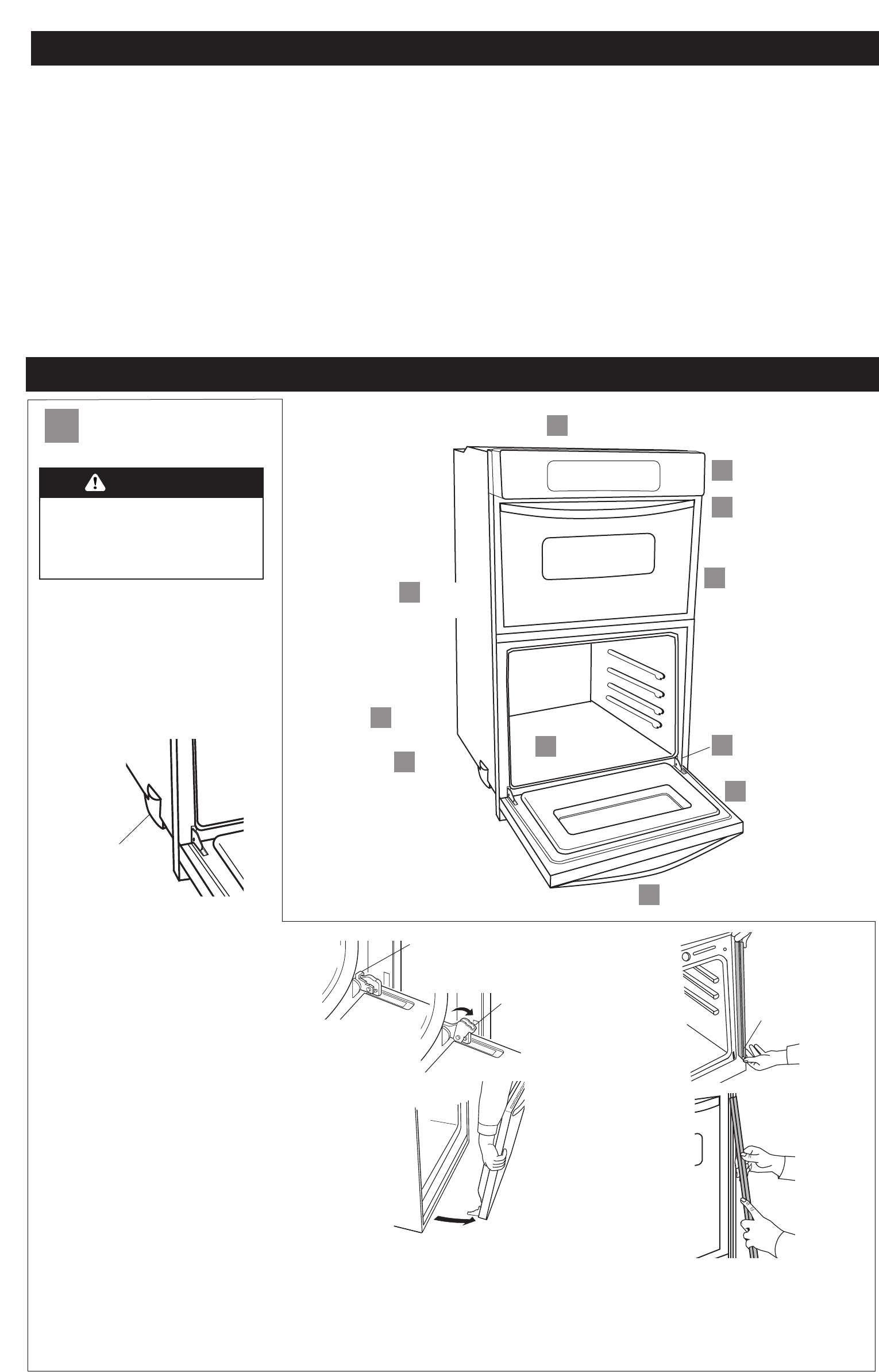
Preparation
A
ARemove
oven door.
ARemove
trim screws.
CReattach side
trim pieces.
CUse screws to attach
oven to cabinet.
ARemove
side trim
pieces.
ARemove
oven racks.
Ashipping
foot
CGrasp oven frame
to lift oven.
DCheck oven and
microwave oven operation.
CReplace
oven door.
Bpower
supply cable
3.Remove trim screws attaching right and
left side trim to oven. Grasp the bottom end of
trim and pull away from oven. Slide top end of
trim downward to remove trim from oven. Take
care not to scratch other surfaces with ends of
trim. Set trim and screws aside on protected
surface.
Remove trim screw.
Pull trim out.
Pull top of trim
down.
1. Turn power supply off. Move oven
close to final position.
• Remove and discard shipping materials,
tape and protective film from the oven. Do
Not remove shipping base or shipping feet
at the front lower corners of oven. The
shipping feet will protect the lower oven
trim until oven is inserted into cabinet.
• Remove and set aside racks and other parts
from inside oven.
Do Not
remove
shipping feet.
If codes permit and a separate grounding wire is
used, it is recommended that a qualified electrician
determine that the grounding path and wire gauge
are in accordance with local codes.
Do Not ground to a gas pipe.
Check with a qualified electrician if you are not
sure oven is properly grounded.
Do Not have a fuse in the neutral or grounding
circuit.
This oven must be connected to a grounding metal,
permanent wiring system.
below at 240 volts (5.4 kW and below at 208
volts) require a separate 30-ampere circuit.
A time-delay fuse or circuit breaker is
recommended.
Connect directly to the fused disconnect (or
circuit breaker box) through flexible, armored
or non-metallic sheathed, copper cable (with
grounding wire).
Flexible armored cable from appliance should
be connected directly to junction box.
Fuse both sides of the line.
A U.L.-listed conduit connector must be
provided at the junction box.
Do Not cut the conduit.
Wire sizes and connections must conform with the
rating of the appliance and to the requirements of
the National Electrical Code, ANSI/NFPA 70 — latest
edition (*, See Page 1) and all local codes and
ordinances.
If the house has aluminum wiring, follow the
procedure below.
a.) Connect the aluminum wiring to the copper
wire using special connectors designed and
Underwriters Laboratories-listed for joining
copper to aluminum. Follow the electrical
connector manufacturer’s recommended
procedure.
b.) Aluminum/copper connection must conform
with local codes and industry-accepted wiring
practice.
Important: Use both hands to remove oven
doors.
Do Not use handle or any portion of the front
frame or trim for lifting.
Before moving oven across floor, check that oven
is on shipping base or slide oven onto cardboard
or hardboard.
Do Not remove shipping feet at the front lower
corners of oven.
Oven must be connected to the proper electrical
voltage and frequency as specified on the
model/serial rating plate. (The model/serial rating
plate is located on the oven door or on the oven
frame.)
Models rated from 7.3 to 9.6 kW at 240 volts
(5.5 to 7.2 kW at 208 volts) require a separate
40-ampere circuit. Models rated at 7.2 kW and
Excessive Weight Hazard
Use two or more people to move and
install oven.
Failure to follow this instruction can
result in back or other injury.
WARNING
2.Completely open oven door. In both back
corners of the door you will see door latches in the
locked position. Rotate both latches forward to the
unlocked position.
Grasp outside edges of door with both hands.
• Begin closing door, at the moment the door
stops closing, lift and pull door toward you.
• Set door aside on a protective surface.
latch on the hinge
in locked position –
door free to open
and close
latch on the hinge
in unlocked
position – door
ready for removal
To get the most efficient use
from your new oven, read your
Use and Care Guide. Keep Installation
Instructions
and Guide close to oven
for easy reference.
This oven is manufactured with white (neutral)
power supply wire and a cabinet-connected bare
grounding wire twisted together.
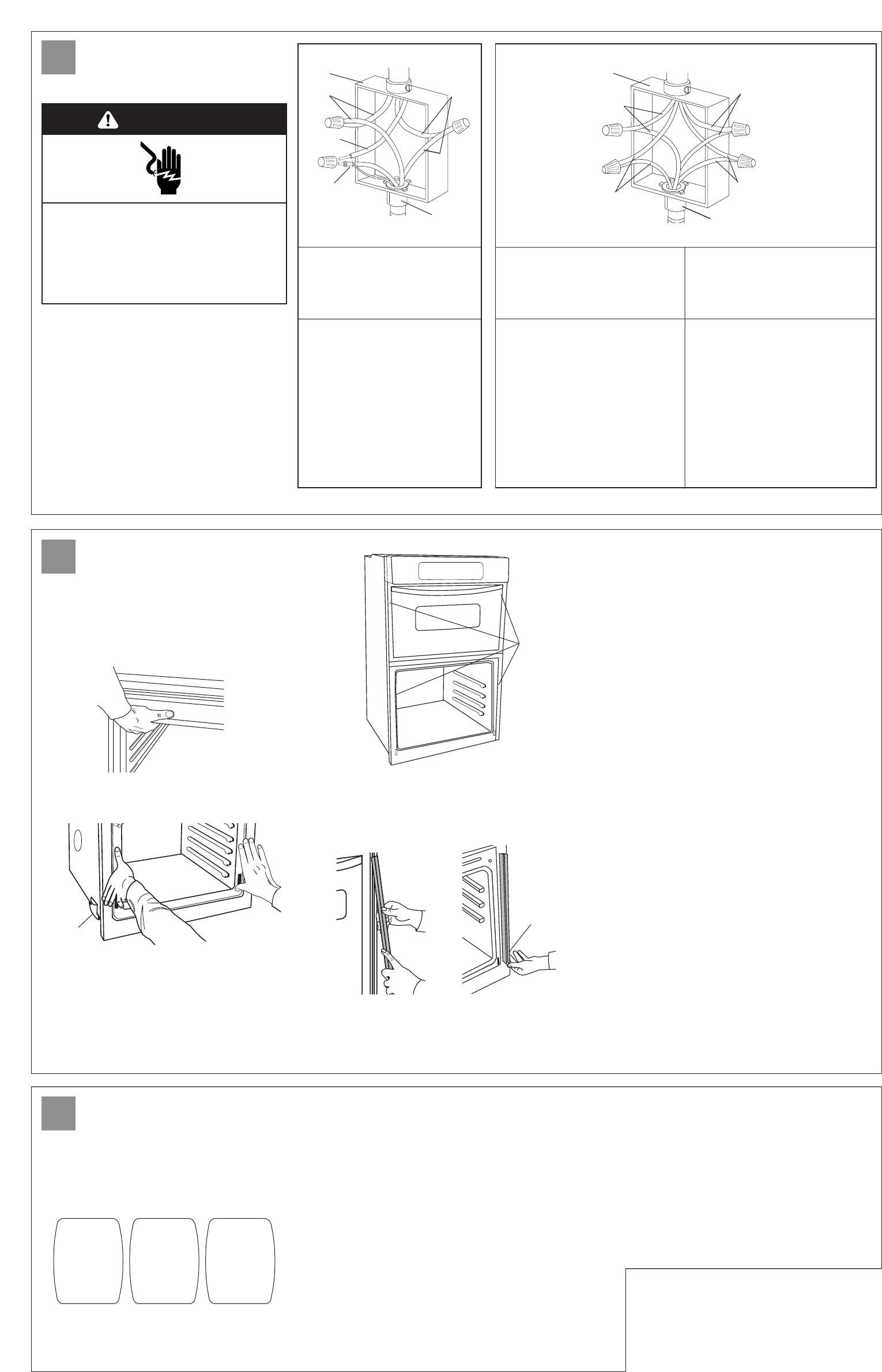
4. Feed oven cable through opening in
the cabinet. Make electrical connection
following the steps needed for your installation.
1. Disconnect the power supply.
2. Remove the junction box cover.
3. Connect oven cable to junction box through the
U.L.-listed conduit connector.
4. Connect the two black wires together with
twist-on connectors.
5. Connect the two red wires together with
twist-on connectors.
6. Complete electrical connection according to
local codes and ordinances.
Figure 1
junction
box
red
wires
white
wire
white and bare
grounding oven
cable wires —
factory crimped
cable from
power supply
black
wires
cable from
oven
U.L.-listed
conduit
connector
Figure 2
cable from
power supply
cable from
oven
junction
box
U.L.-listed conduit
connector
red
wires
white
wires
black wires
bare grounding
wires
If local codes PERMIT
connecting cabinet-grounding
conductor to neutral white
wire in junction box:
If local codes DO NOT PERMIT
connecting cabinet-grounding
conductor to neutral white
wire in junction box:
If connecting to a
four-wire electrical system:
7. Connect the factory-crimped bare
and white oven cable wires to
the neutral (white) wire in
junction box. See Figure 1.
8. Replace junction box cover.
7. Separate the factory-crimped
bare and white oven cable wires.
8. Connect white oven cable wire to
neutral (white) wire in junction
box. See Figure 2.
9. Connect the bare grounding
oven cable wire to a grounded
wire in the junction box. See
Figure 2.
10. Replace junction box cover.
7. Separate bare and white
oven cable wires.
8. Connect white oven cable wire to
neutral (white) wire in junction
box. See Figure 2.
9. Connect the bare grounding oven
cable wire to the green grounding
wire in junction box. Do Not
connect bare grounding wire to
neutral (white) wire in junction
box. See Figure 2.
10. Replace junction box cover.
Carefully push against seal area of oven front
frame when pushing oven into cabinet.
Do Not push against outside edges.
5.Lift oven into cabinet cutout using the
oven opening as an area to grip.
Page 3
Push against seal area of front frame to push
oven into cabinet until shipping feet almost
contact cabinet. Use a Phillips screwdriver to
remove screws attaching shipping feet. Remove
and discard shipping feet.
Push oven completely into cabinet and center
oven in cabinet cutout.
8.Replace oven racks.
11. Check the operation of your lower
oven. Press the “BROIL” pad. “BROIL” will
appear in the display. Press the “START” pad.
12. Check the operation of the
microwave oven.
• Fill a microwave-safe container with one cup of
water and place container inside microwave oven.
Close door firmly.
• Set microwave oven cook time to “2:00”
minutes.
• Press the “START/ENTER” pad. The interior
microwave oven light should be on and the
remaining cooking time should be displayed.
Electrical connection
B
Attachment
C
Check operation
D
Push trim
into place.
Replace
trim screw.
Slide top
of trim up.
10. Turn on power supply. The display
panel will light up briefly. “PF” should appear in
the temperature display.
Make sure the oven door is closed and the “ON”
light is shown in the display area. After 2 minutes,
partially open oven door. You should feel heat from
the oven. Press the “CANCEL” pad.
If your oven does not heat or an“F” appears in
the display, contact your dealer or check the “If
you need service...” section of this Installation
Instructions.
• When display reads “1:00,” open microwave
oven door. The microwave should stop cooking.
• Close door firmly. The interior microwave oven
light should turn off.
• Press the “START/ENTER” pad. Microwave oven
should begin cooking and the microwave oven
interior light should be on.
• Let microwave oven complete cooking time. A
tone will sound four times at end of cooking time
and microwave oven will shut off.
• Open microwave oven door and carefully remove
container. Water in container should be hot.
BAKE BROIL CLEAN
shipping
foot
6.Important: Securely fasten oven to cabinet
using the screws provided (two screws for a single
oven or four screws for a double oven). Insert the
screws through holes in mounting rails. Do Not
overtighten screws.
7. Slide top end of each trim upward onto oven
side rails. Push each trim into place at bottom of
trim. Use screws to attach each trim to oven. Take
care not to scratch other surfaces with ends of trim.
4 screws
Electrical Shock Hazard
Turn power supply off before connecting wires.
Use 8 gauge solid copper wire.
Electrically ground range.
Failure to follow these instructions can result
in death, fire, or electrical shock.
WARNING
If your house has aluminum wiring, see
“Electrical requirements”, Page 2.
9. Reinstall the oven door by inserting
ends of hinges into hinge slots in the oven
frame. Push hinges in as far as they will go.
Open the door (you will feel the door drop
into place) and rotate both hinge latches back
to the locked position.
Close and open the door to check that the
door closes and opens completely. If door
does not close or open completely, repeat
the door removal step and reinstall door as
described above.

If oven does not operate:
Check that circuit breaker is not tripped or
house fuse blown.
See Use and Care Guide for troubleshooting list.
If you need assistance:
If you have questions about operating, cleaning or
maintaining your oven:
Refer to Use and Care Guide.
Call the Consumer Assistance Center: Check
your Use and Care Guide for a toll-free
number to call or call the dealer from whom you
purchased this appliance. The dealer is listed in
the Yellow Pages of your phone directory under
“Appliances — Household — Major — Service
and Repair.”
Part No. 8300653
© 2001 Printed in U.S.A.
Quick Reference
Table of Contents:
Pages
Product dimensions
Cutout dimensions
Before you start
Electrical requirements
Installation steps
If you need assistance:
Check your Use and Care Guide for a toll-free number to call or call
the dealer from whom you purchased this appliance. The dealer is
listed in the Yellow Pages of your phone directory under
“Appliances — Household — Major — Service and Repair.”
Call when you:
Have questions about built-in oven installation or operation.
Need to obtain the name and number of an authorized service
company.
When you call, you will need:
The built-in oven model number.
The built-in oven serial number.
Both numbers are listed on the model/serial rating plate, located on
the microwave oven frame.
1
1
1
2
23
IMPORTANT:
Read and save these instructions.
Installation Instructions
IMPORTANT:
Installer: Leave Installation Instructions with the homeowner.
Homeowner: Keep Installation Instructions for future reference.
Save Installation Instructions for local electrical inspector's use.
Part No.
8300653
27" and 30" Electric
Built-in Microwave/
Oven Combination
If you need service:
Maintain the quality built into your built-in oven by
calling an authorized service company.
To obtain the name and number of an authorized
service company:
Contact the dealer from whom you purchased
your built-in oven; or
Look in the Yellow Pages of your telephone
directory under “Appliances — Household —
Major — Service and Repair” for an authorized
service company; or
Call the Consumer Assistance Center. The toll-
free number is listed in your Use and Care Guide.
When you call, you will need:
The built-in oven model number.
The built-in oven serial number.
Both numbers are listed on the model/serial rating
plate, located on the microwave oven frame.