Winnix Technologies HYM360 UHF RFID Reader Module User Manual user s manualx
Winnix Technologies Co., Limited UHF RFID Reader Module user s manualx
Manual
UHF RFID Reader Module
UHF RFID Reader Module
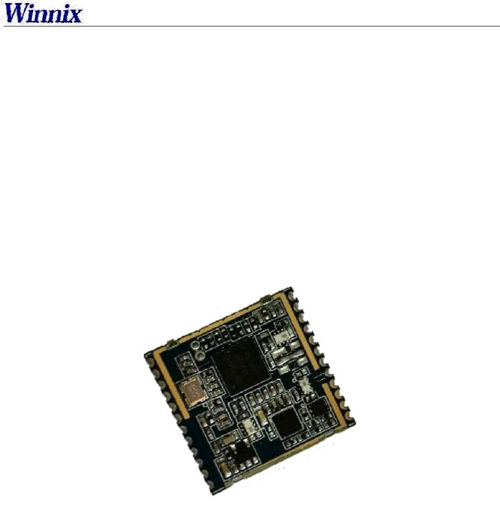
HYM360
WinnixTechnologiesCo.,Limited
UHF RFID Reader Module
Brief Introduction
HYM360 UHF Reader Module complied with EPC C1G2 Protocol, its working frequency is
902.75-927.25MHz, with standard 2dBi antenna, the reading distance can reach 2 meters. With low
power consumption, simple power supply and interface circuit, a high-performance and cost-effective
RFID system can be established. It is suitable for retail,access control, medical industry, food tracking,
anti-counterfeit and so on, especially for small size hand-held UHF RFID reader.
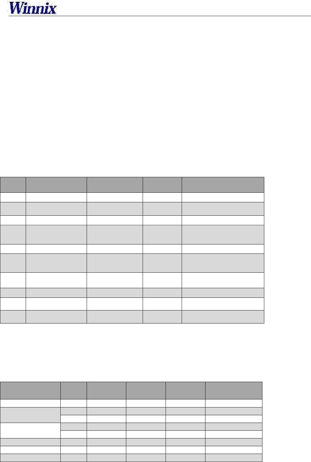
Technical Date
No. Item Technical Date Unit Remark
1 Fixed Current ≤380 mA 25dBm
2 Standby Current ≤1 mA EN Pin Low Level
3 Frequency Range 902.75-927.25 MHz
4 Default Working
Frequency
Hopping
Frequency MHz Frequency Interval 250KHz
5 Fixed Power 25 dBm Max 27dBm
6 Stepping Interval 1 dBm 10~25dBm adjustable by
soft
7 Label Protocol EPC C1G2
/ISO18000-6C
8 Starting Time ≤50 ms
9 VSWR ≤1.5
10 Max Reading Range 2 m 2dBi Antenna
Characteristics of DC
Data Min
Value Typical
Value Max
Value Unit Remark
Voltage of Power 3.3 4.2 5 V DC
Input High Level 2 3.3 3.5 V GPIO
2 - 5 V EN
Input Low Level -0.5 0 0.5 V GPIO
- - 0.18 V EN
Output High Level 2.3 - 3.3 V GPIO
Output Low Level 0 - 1 V GPIO
Enable Current 2 5 25 uA VEN≥2V
UHF RFID Reader Module
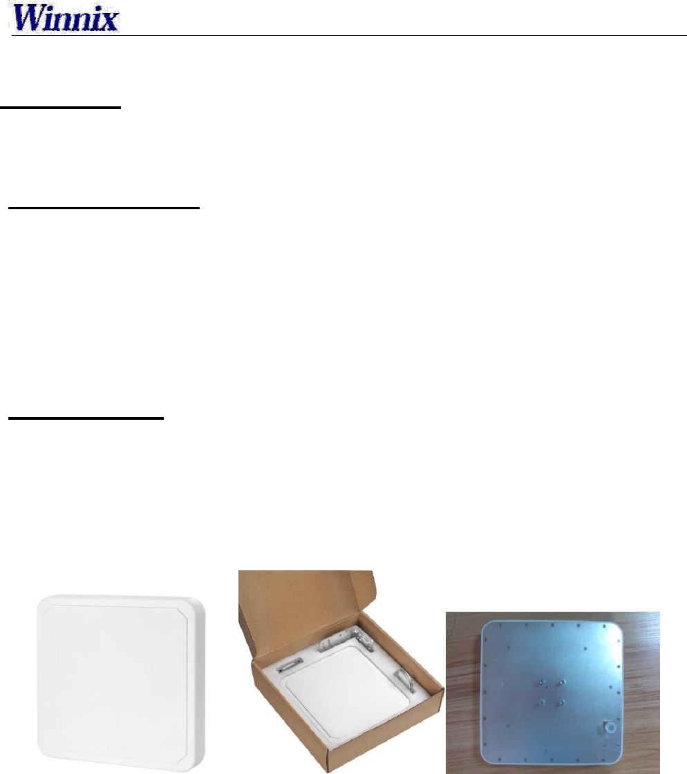
Requirement on Antenna
Product Features
Electrical Properties: It is a general antenna for UHF RFID applications with high gain and low VSWR.
Mechanical Properties: The compact and artistic antenna is suitable for all kinds of severe
environment
for its dual waterproof design with Gasket and silicone and strengthening rib of shell.
Performance Specifications
Frequency Range:860MHz~960MHz
Maximum VSWR: ≤1.3:1
Gain: > 9 dBi
H side HPBW: 70°
E side HPBW: 70°
Polarization: Circular Polarization
Relative humidity: 5%~95%
Input Impedance: 50 Ω
Antenna Connection: N-50KFD (Type N Female)
Physical specifications
Size: 258mm×258mm×56mm
Weight: 0.91kg(without bracket)
Material: Engineering Plastic ASA、Aluminums
Color: Ivory-white
Enclosure Rating: IP67
Operational Temperature: -40℃~+ 85℃
Storage Temperature: -40℃~+ 85℃
Figure 1. The photograph of the antenna
UHF RFID Reader Module
Installation guide
HYN503 antenna can be installed on steal framed structure or bracket by own antenna bracket, and
connect with reader with coaxial line. The antenna can be installed horizontally or vertically, it is
decided
by installation location, the angle can be adjusted after installation according to the real
environment.
Antenna bracket is an optional accessory, you can choose according to your special requirement.
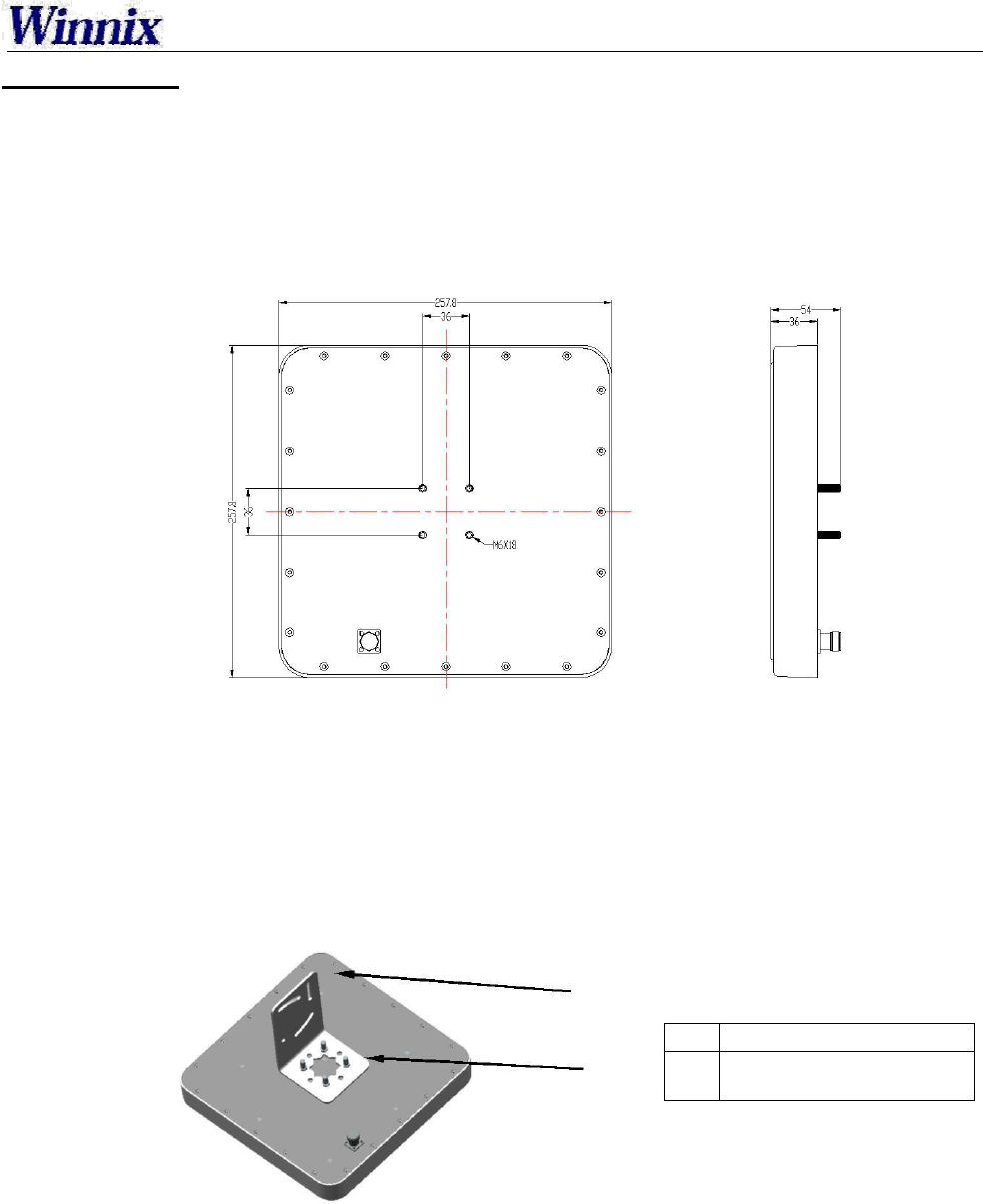
1. Installation Dimension
Figure 2 Dimension of the antenna
2. Installation Steps
2.1 Horizontal Installation
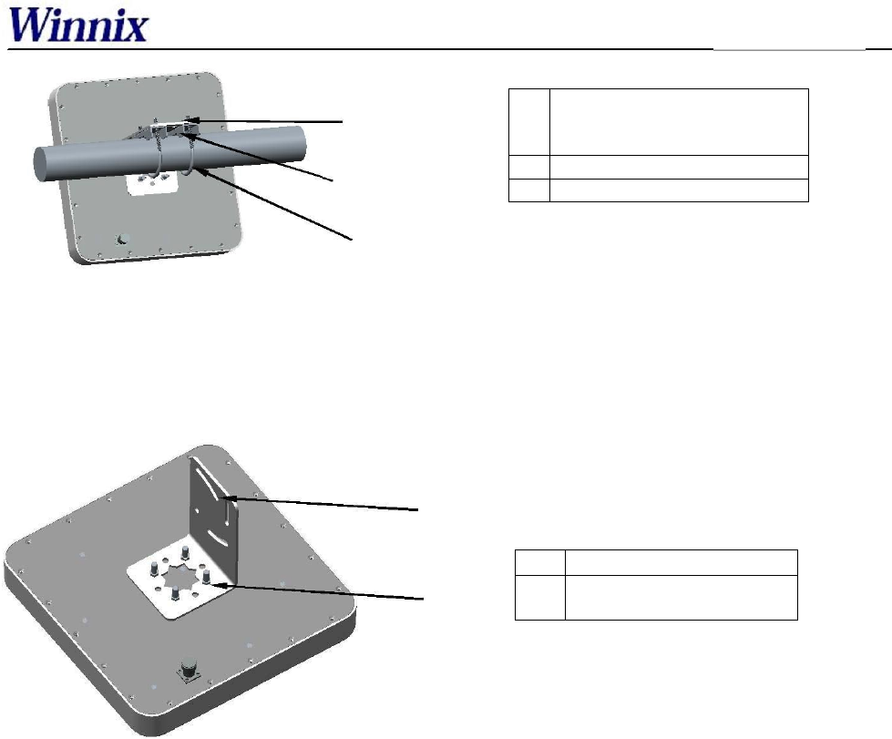
Step 1:Use M6 screw, elastic washer and plain washer, to fix the L board on the antenna, please see
Figure 3:.
Figure 3 The structure for the Step 1 in the first case
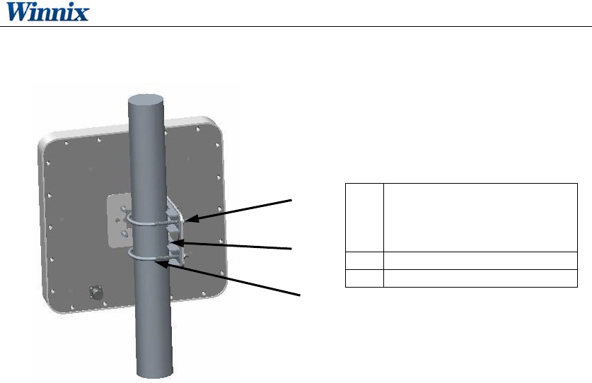
Step 2:Please use M6 screw, elastic washer and plain washer and “Dog tooth” to fix it on the
horizontal and vertical bracket, please see Figure 4.
1 L board(Bracket)
2.M6 screw, elastic
washer and plain washer
UH
F
Antenna
1 M6 screw, elastic
washer
and plain
h
2 Dog tooth
3 M6 U style screw bolt
Figure 4. The structure for the Step 2 in the first case
2.2 Vertical Installation
Step 1:Use M6 screw, elastic washer and plain washer, to fix the L board on
the antenna, as
shown in Figure 5.
Figure 5 The structure for the Step 1 in the second case
Step 2:Please use M6 screw, elastic washer and plain washer and “Dog tooth” to fix it
on the horizontal
and vertical bracket, as shown in Figure 6.
1 L board(Bracket)
2.M6 screw, elastic
washer and plain washer
UHF RFID Reader Module
6 / 9
Figure 6 The structure for the Step 2 in the second case
1 M6 screw, elastic
washer and plain
washer
2 Dog tooth
3 M6 U style screw bolt
UHF RFID Reader Module
7 / 9
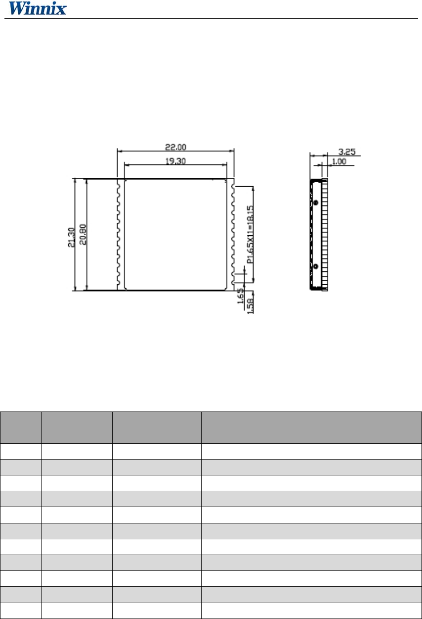
Appearance and Structure
Drawing 1 Size of Reader Module
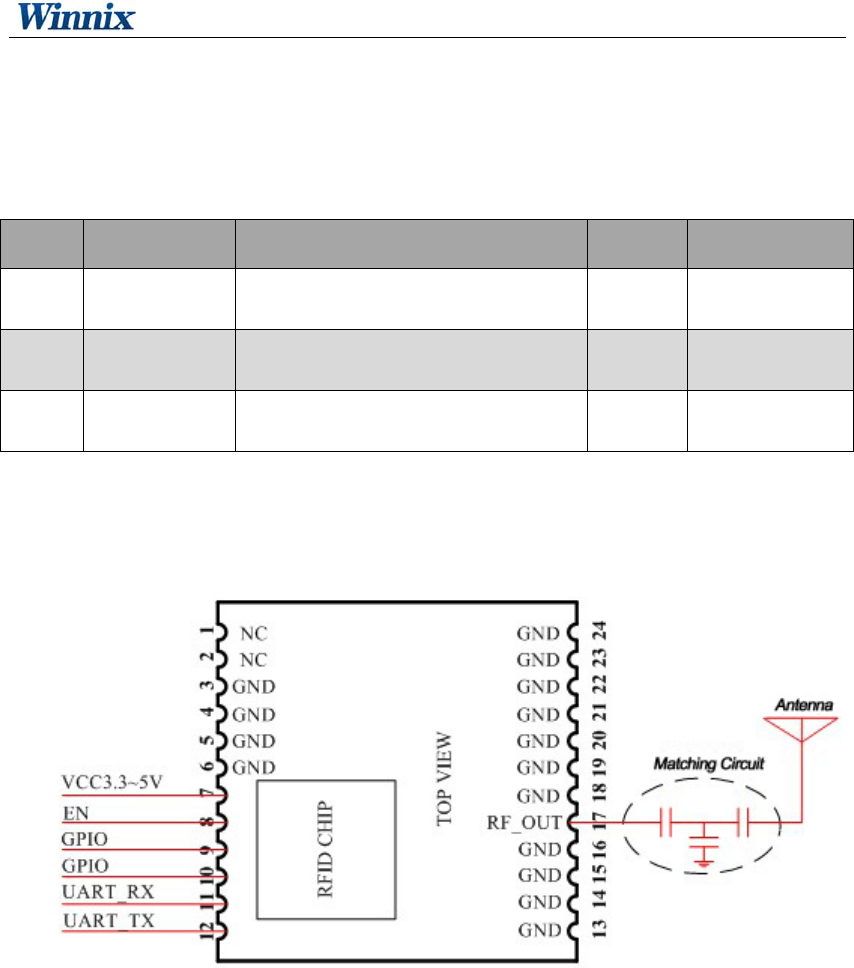
Interface Definition
PIN Signal
Name
Signal
Direction
Function/Compatibility Description
1~2 NC NC
3~6 GND - Module Connecting Ground
7 VDD Input Module Supplying power
8 EN Input Module Enabling, Highly Effective
9 GPIO Output
10 GPIO Output
11 UART_RX Input
12 UART_TX Output
13~16 GND - Module connecting ground
17 RFOUT Bidirection Module Radio frequency Input and output interface
18~24 GND - Module connecting ground
UHF RFID Reader Module
8 / 9
Environment Requirement
No. Item Technical Data Unit Remark
1 Working
temperature -20~+70 ℃
2 Storage
temperature -40~+85 ℃
3 Relative
humidity 10%~90% RH
Circuit for Reference
Drawing 2 Circuit for reference
Warning
This device complies with Part 15 of the FCC Rules. Operation is subject to the following two
conditions: (1) this device may not cause harmful interference, and (2) this device must accept
any interference received, including interference that may cause undesired operation.
changes or modifications not expressly approved by the party responsible for compliance
could void the user's authority to operate the equipment.
UHF RFID Reader Module
9 / 9
NOTE: This equipment has been tested and found to comply with the limits for a
Class B digital device, pursuant to Part 15 of the FCC Rules. These limits are
designed to provide reasonable protection against harmful interference in a
residential installation. This equipment generates, uses and can radiate radio
frequency energy and, if not installed and used in accordance with the
instructions, may cause harmful interference to radio communications. However,
there is no guarantee that interference will not occur in a particular installation.
If this equipment does cause harmful interference to radio or television reception,
which can be determined by turning the equipment off and on, the user is
encouraged to try to correct the interference by one or more of the following
measures:
-- Reorient or relocate the receiving antenna.
-- Increase the separation between the equipment and receiver.
-- Connect the equipment into an outlet on a circuit different
from that to which the receiver is connected.
-- Consult the dealer or an experienced radio/TV technician for help.
RF Exposure Statement
To maintain compliance with FCC’s RF Exposure guidelines, This equipment should be
installed and operated with minimum distance between 20cm the radiator your body: Use
only the supplied antenna.
If the FCC identification number is not visible when the module is installed inside another device,
then the outside of the device into which the module is installed must also display a label
referring to the enclosed module. This exterior label can use wording such as the following:
“Contains Transmitter Module FCC ID: RVZHYM360” or “Contains FCC ID: RVZHYM360”
Please describe the following warning to the manual.
This LMA is tested and approved as standalone configuration, additional evaluation may be
required for any system integrated this radio module.