Wireless 2000 RF and UWB Technologies 20000310 PAM 3000 Bed Sensor Panel User Manual 100 100 19 04
Wireless 2000 RF & UWB Technologies Ltd. PAM 3000 Bed Sensor Panel 100 100 19 04
Contents
- 1. Instalation and Maintenance Guide
- 2. Instructions For Use
- 3. Instruction For Use
Instalation and Maintenance Guide

Patient Assessment Monitor
PAM™3000
Installation and
Maintenance Guide
Document p/n 100.100.19.04
Page 1 of 7
Rev 04
DOCUMENT TITLE Installation and
Maintenance Guide
DOCUMENT #: 100.100.19.04
DOCUMENT REVISION #: 04
REVISION HISTORY
Revision
Date Reason For Change Author
00 09.Mar.2006 Preliminary Draft E. Gavrilovich
01 07.Apr.2008
Rev history and FCC standards added,
Environmental conditions changed as in CSA
report
Eli A
02 22.Apr.2008 P/N added to “System Hardware Installation”,
troubleshooting table added Eli A
03 29.May.2008 Grammatical and spelling errors fixed Eli A
03 14.Jul.2008 BSI&CSA logo removed, FCC notice included Eli A
Proprietary Information
This document contains proprietary information which is protected by copyright. All rights reserved. Reproduction, adaptation,
or translation without prior written permission is prohibited, except as allowed under the copyright laws.
Wireless 2000 RF & UWB Technologies Ltd.
2421 Alpha Avenue
Burnaby, BC, V5C 5L2
Canada

Patient Assessment Monitor
PAM™3000
Installation and
Maintenance Guide
Document p/n 100.100.19.04
Page 2 of 7
Rev 04
1 Introduction
This Guide provides safety information, maintenance guidelines and cleaning
instructions for the PAM™3000 Patient Assessment Monitor system.
2 System Description
PAM™3000 is for use in the US and Canada. The PAM™3000 system consists of
Bed Sensor (200.003.10.00), RBS Repeater Base Station (200.001.10.00), CBS
Central Base Station (200.002.10.00) and software.
3 System Hardware Installation
3.1 Installing the Bed Sensor
Regulatory Notice
This equipment may only be operated indoor. Operations
outdoor is in violation of 47 U.S.C. 301 and could subject the
operator to serious legal penalties
FCC information
Product Name: PAM 3000 Bed Sensor Panel
Model number: WHQ20000310
3.1.1 Step 1: Power Supply
Find the power supply in the shipping box and unpack it.
Only the approved Power Supply (Wireless2000 p/n 375.001.10.00) and
Power Cord (Wireless2000 p/n 506.001.10.00) shipped with PAM™3000
should be used.
Attach the power supply to the closest to the headboard tubular crossbar of the bed
frame with the Velcro ties as shown. Route DC output cable as shown and fasten it
with the Velcro ties to the bed frame. The DC plug should be placed near the top
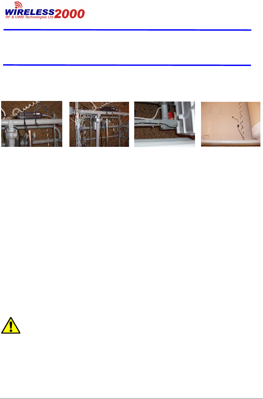
Patient Assessment Monitor
PAM™3000
Installation and
Maintenance Guide
Document p/n 100.100.19.04
Page 3 of 7
Rev 04
section of the bed surface, as shown. Route AC power cord as shown and fasten it
with the Velcro ties to the bed frame. Plug the AC power cord into the approved AC
wall outlet.
3.1.2 Step 2: Bed Sensor
Unpack the bed sensor. Record its serial number and the room number for the
location identification during the admission procedure. Pull up or slide down the bed
mattress to expose the top section of the bed. Place bed sensor on the bed 18” (46
cm) away from the headboard and ensure that bed sensor’s plastic cover is facing
up and the bed sensor’s DC power jack is oriented toward the footboard. Insert DC
plug of the power supply into the DC jack of the bed sensor and tighten the outer
ring of the plug to prevent its accidental unplugging.
3.1.3 Step 3: Calibration
To perform successful self-calibration procedure, ensure that the bed is vacant and
there is no motion within 1 meter from the bed for 10 minutes. The bed sensor is
now calibrated and ready for integration into the PAM system.
3.2 Installing the Repeater Base Station (RBS):
The locations to install the RBSs and the necessary number of RBS
units were determined during the Initial Facility Assessment (IFA).
Please consult the IFA Report.
Install the RBS up on the wall near the ceiling by using mounting screws supplied.
Attach the DC plug of the DC power adapter (supplied) to the RBS DC jack and
insert the AC plug into the nearest AC wall receptacle. Alternately, the RBS may be
mounted above the suspended ceiling.

Patient Assessment Monitor
PAM™3000
Installation and
Maintenance Guide
Document p/n 100.100.19.04
Page 4 of 7
Rev 04
3.3 Installing the Central Base Station (CBS):
The system requires only one CBS unit per facility’s floor.
Install the CBS by plugging its cable into the USB port of designated PC and placing
the unit on the desk next to PC. For proper operation ensure that the label on the
CBS enclosure is facing up. Improper orientation of the CBS may greatly decrease
system’s communication range.
4 Replacement Parts List
200.003.10.00 – Bed Sensor
200.001.10.00 – Repeater Base Station
200.002.10.00 – Central Base Station
5 Technical Information
Model:
PAM™3000
Type of protection against electric shock: Class 1
Degree of protection against electric shock: Type BF, Applied part
6 Environmental Specifications:
6.1 Operating
Ambient temperature range: 10°C to 40°C (50°F to 104°F)
Relative humidity: 30% to 75%, non-condensing
Altitude: Sea level to 3000m max (10,000 Ft)
6.2 Transport and Storage
Ambient temperature range: -10°C to +60°C (+14°F to 140°F)
Relative humidity: 5% to 95%, non-condensing
Altitude: Sea level to 12,000m (40,000 Ft)

Patient Assessment Monitor
PAM™3000
Installation and
Maintenance Guide
Document p/n 100.100.19.04
Page 5 of 7
Rev 04
6.3 Applicable Requirements:
UL 60601-1 (1
st
Edition) Medical Electrical Equipment, Part 1: General
Requirements for Safety
IEC 601-1:1988 + A1:1991 + A2:1995
Safety of Medical Electrical Equipment, Part 1: General Requirements for Safety
IEC/EN 60601-1-2 Medical Electrical Equipment, Part 1: General Requirements for
Basic Safety and Essential Performance. Collateral standard, EMC Safety
With respect to ELECTRICAL SHOCK, FIRE, MECHANICAL and OTHER
specified hazards in accordance with
CAN/CSA C22.2 No.601.1- M90
Safety of Medical Electrical Equipment, Part 1: General Requirements for Safety
CAN/CSA C22.2 No.601.1S1-94
Supplement No. 1-94 to CAN/CSA C22.2 601.1-M90
CAN/CSA C22.2 No.601.1B-98
Amendment 2 to CAN/CSA C22.2 601.1-M90
EN 61000-4, IEC 61000-4 in accordance with FCC part 15/B, 15/C, 15/F
Power Supply complies with UL60601-1, UL60950-1, CSA C22.2 601-1, CSA C22.2
60950-1, EN60601-1 and EN60950-1.
Power Supply Cord complies with UL 60601-1.
7 Maintenance Schedule
Maintenance Frequency Procedure
Inspect the power cord Daily (when not in use)
Examine the AC power
plug for damage. Make
sure that the prongs of
the plug do not move in
the casing. If damaged,
replace the Power Cord
with the appropriate
Wireless 2000 Power
Cord.
Cleaning As needed See “Cleaning
Procedure”
Safety checks according
to IEC 601-1
At least once every two
years, after any repairs
See your qualified
service personnel for

Patient Assessment Monitor
PAM™3000
Installation and
Maintenance Guide
Document p/n 100.100.19.04
Page 6 of 7
Rev 04
or as needed additional information
Functional Testing
When functional defects
in measurements are
suspected
See your qualified
service personnel for
additional information
Performance Assurance
At least once every year,
or as needed (when
functional defects in
measurements are
suspected)
See your qualified
service personnel for
additional information
8 Cleaning Procedure
Warning:
- Do not immerse the Bed Sensor, RBS or CBS in liquid or use caustic
or abrasive cleaners.
- Do not spray or pour any liquid on the Bed Sensor, RBS or CBS.
- Do not allow any liquid to penetrate connectors or openings in the Bed
sensor’s chassis.
To clean the Bed Sensor, dampen a cloth with commercial, non-abrasive cleaner
and wipe off the top and sides of the plastic cover.
If liquid is accidentally spilled on the Bed Sensor, clean and dry it thoroughly before
reuse.
If in doubt about the Bed Sensor’s safety, refer the unit to qualified service
personnel.
9 Troubleshooting
The table below will help intended user to troubleshoot possible problems without
any external help from Wireless2000’s tech-support personnel. However, if any
technical problems appeared, save the description of the problem into the log file for
the further investigation.
Problem Solution
1)
“No Data” received on GUI/ No Communication
Possible cause
a) Bed Sensor’s power
-check power adaptor to

Patient Assessment Monitor
PAM™3000
Installation and
Maintenance Guide
Document p/n 100.100.19.04
Page 7 of 7
Rev 04
unplugged
b) RBS’s power unplugged
c) RBS is not associating with
CBS
make sure power jack is
connected. If it was
disconnected, plug it in
and proceed with
calibration routine (See
System Hardware
Installation Step 3 for
reference).
-check LED indicator on
RBS. If it is “OFF” (no
light) than make sure
RBS’s Power Supply is
connected. Reconnect it in
case it was unplugged.
Otherwise, if it is
connected, call
Wireless2000’s tech-
support personnel.
-Reset the RBS by
disconnecting its power
jack and connecting again.
2)
“Error” display on the monitor (GUI)
Possible cause
d) Failed calibration of Bed
Sensor
-Unplug Bed Sensor and
plug it back. Make sure
there is no motion one
meter within the Bed
Sensor for at least 1
minute.
©Copyright 2007 Wireless 2000
All Rights Reserved
Printed in Canada