Wireless Seismic 00102 Wireless Remote Unit User Manual DeploymentGuide
Wireless Seismic, Inc. Wireless Remote Unit DeploymentGuide
Contents
- 1. Users Manual 1
- 2. Users Manual 2
Users Manual 1

5Mbps Draft
Real Time Matters
Wireless Seismic, Inc.
13100 Southwest Freeway, Suite 150
Sugar Land, TX 77478
832.532.5080
RT 1000
Deployment Guide
January 31, 2012
Part Number: 90-0004
R03.h

5Mbps Draft
To order additional copies of this document, send an email to your sales representative
requesting the following:
Part Number: 90-0004-PDF
Part Number: 90-0004-Paper
© 2010-2012 Wireless Seismic, Inc. All rights reserved.
All other brands, company names, product names, trademarks or service marks referenced in this material are the
property of their respective owners, who may or may not be affiliated with, connected to, or sponsored by Wireless
Seismic, Inc.
Wireless Seismic, Inc.'s trademarks, registered trademarks or trade dress may not be used in connection with any
product or service that is not the property of Wireless Seismic, Inc., in any manner that is likely to cause confusion
among customers, or in any manner that disparages or discredits Wireless Seismic, Inc. The products and services
described in this material may not be available in all regions.
All information supplied in this Deployment Guide regarding weights, sizes, performance, functionality and other
technical information of any kind is approximate and shall be taken as generally representing our products. We may
modify our products, discontinue products or add new products at any time and without providing an update to this
Deployment Guide.
NOTHING CONTAINED IN THIS DEPLOYMENT GUIDE SHALL BE CONSIDERED A REPRESENTATION OR WARRANTY
MADE BY WIRELESS SEISMIC, INC. (“WIRELESS SEISMIC”) CONCERNING ANY PRODUCT DESCRIBED HEREIN, OR
OTHERWISE. EXCEPT FOR THE WARRANTIES THAT MAY BE PROVIDED IN A SEPARATE AGREEMENT BETWEEN YOU
AND WIRELESS SEISMIC, WIRELESS SEISMIC MAKES NO REPRESENTATION OR WARRANTY OF ANY KIND AND NO
WARRANTY, CONDITION OR REPRESENTATION, WHETHER EXPRESS, IMPLIED, ORAL OR STATUTORY, IS PROVIDED TO
YOU OR ANY THIRD PARTY. WITHOUT LIMITING THE FOREGOING, WIRELESS SEISMIC EXPRESS EXCLUDES AND
DISCLAIMS ANY WARRANTY, CONDITION OR REPRESENTATION: (1) OF MERCHANTABILITY, FITNESS FOR A
PARTICULAR PURPOSE, TITLE, SATISFACTORY QUALITY, OR ARISING FROM A COURSE OF DEALING, USAGE, OR
TRADE PRACTICE; (2) THAT ANY PRODUCTS (INCLUDING SOFTWARE) WILL BE FREE FROM INFRINGEMENT OR
VIOLATION OF ANY RIGHTS, INCLUDING INTELLECTUAL PROPERTY RIGHTS, OF THIRD PARTIES; OR (3) THAT THE
OPERATION OF ANY PRODUCT (INCLUDING SOFTWARE) WILL BE UNINTERRUPTED OR ERROR FREE. THIS
DISCLAIMER AND EXCLUSION SHALL APPLY EVEN IF THE EXPRESS WARRANTIES HEREIN FAIL OF THEIR ESSENTIAL
PURPOSE.

5Mbps Draft
RT 1000 1.5.0 3 Deployment Guide R03.h
© 2010-2012 Wireless Seismic, Inc. All rights reserved.
Table of Contents
1.1. Overview . . . . . . . . . . . . . . . . . . . . . . . . . . . . . . . . . . . . . . . . . . 9
1.1 About this Guide . . . . . . . . . . . . . . . . . . . . . . . . . . . . . . . . . . . . . . 9
1.2 Who Should Use this Guide . . . . . . . . . . . . . . . . . . . . . . . . . . . . . . . 9
1.3 Related Documents . . . . . . . . . . . . . . . . . . . . . . . . . . . . . . . . . . . . 9
1.4 Getting Help . . . . . . . . . . . . . . . . . . . . . . . . . . . . . . . . . . . . . . . . . 9
2.2. Layout . . . . . . . . . . . . . . . . . . . . . . . . . . . . . . . . . . . . . . . . . . . .11
2.1 Prerequisites . . . . . . . . . . . . . . . . . . . . . . . . . . . . . . . . . . . . . . . . 11
2.2 Getting Ready . . . . . . . . . . . . . . . . . . . . . . . . . . . . . . . . . . . . . . . 11
2.3 Preparing the Equipment. . . . . . . . . . . . . . . . . . . . . . . . . . . . . . . . 13
2.4 Setting Up the Central Recording System . . . . . . . . . . . . . . . . . . . . 13
2.4.1 Setting up the Computer . . . . . . . . . . . . . . . . . . . . . . . . . . . . 13
2.4.2 Connecting to the Source Controller . . . . . . . . . . . . . . . . . . . . 13
2.4.3 Source Interface Cables . . . . . . . . . . . . . . . . . . . . . . . . . . . . . 20
2.4.4 Trigger Pin-Outs . . . . . . . . . . . . . . . . . . . . . . . . . . . . . . . . . . 22
2.5 Laying Out the Equipment. . . . . . . . . . . . . . . . . . . . . . . . . . . . . . . 25
2.5.1 Prerequisites. . . . . . . . . . . . . . . . . . . . . . . . . . . . . . . . . . . . . 25
2.5.2 Assembling the Ground Equipment . . . . . . . . . . . . . . . . . . . . . 26
2.5.3 Placing the WRU in the Field . . . . . . . . . . . . . . . . . . . . . . . . . . 28
2.5.4 Placing the BSU in the Field . . . . . . . . . . . . . . . . . . . . . . . . . . 30
3.3. Backhaul . . . . . . . . . . . . . . . . . . . . . . . . . . . . . . . . . . . . . . . . . .31
3.1 Overview. . . . . . . . . . . . . . . . . . . . . . . . . . . . . . . . . . . . . . . . . . . 31
3.2 Backhaul Components . . . . . . . . . . . . . . . . . . . . . . . . . . . . . . . . . 35
3.2.1 BSU Components . . . . . . . . . . . . . . . . . . . . . . . . . . . . . . . . . 35
3.2.1.1 BSU . . . . . . . . . . . . . . . . . . . . . . . . . . . . . . . . . . . . . . . 35
3.2.1.2 PoE Switch Unit . . . . . . . . . . . . . . . . . . . . . . . . . . . . . . . 36
3.2.1.3 Battery and Power Supply . . . . . . . . . . . . . . . . . . . . . . . . 37
3.2.1.4 Cables. . . . . . . . . . . . . . . . . . . . . . . . . . . . . . . . . . . . . . 38
3.2.2 Antennas . . . . . . . . . . . . . . . . . . . . . . . . . . . . . . . . . . . . . . . 39
3.2.3 Radio Kit Components . . . . . . . . . . . . . . . . . . . . . . . . . . . . . . 39
3.2.3.1 FM1100 Radio . . . . . . . . . . . . . . . . . . . . . . . . . . . . . . . . 40
3.2.3.2 FM3100 Radio . . . . . . . . . . . . . . . . . . . . . . . . . . . . . . . . 41
3.2.4 Mast Kit Components. . . . . . . . . . . . . . . . . . . . . . . . . . . . . . . 41
3.2.4.1 Mast . . . . . . . . . . . . . . . . . . . . . . . . . . . . . . . . . . . . . . . 42
3.2.4.2 Base . . . . . . . . . . . . . . . . . . . . . . . . . . . . . . . . . . . . . . . 42
3.2.4.3 Bag. . . . . . . . . . . . . . . . . . . . . . . . . . . . . . . . . . . . . . . . 45
3.2.4.4 Backpack Kit . . . . . . . . . . . . . . . . . . . . . . . . . . . . . . . . . 45

5Mbps Draft
4 RT 1000 1.5.0 Deployment Guide R03.h
© 2010-2012 Wireless Seismic, Inc. All rights reserved.
Table of Contents
3.3 Configure the Radios . . . . . . . . . . . . . . . . . . . . . . . . . . . . . . . . . . .46
3.3.1 Create a Private Network. . . . . . . . . . . . . . . . . . . . . . . . . . . . .46
3.3.2 Setting NIC Priority. . . . . . . . . . . . . . . . . . . . . . . . . . . . . . . . .54
3.3.3 Configure the Radio . . . . . . . . . . . . . . . . . . . . . . . . . . . . . . . .56
3.3.4 Restore your Network Settings. . . . . . . . . . . . . . . . . . . . . . . . .59
3.3.5 Using the Fluidmesh Interface to Scan . . . . . . . . . . . . . . . . . . .59
3.3.6 Using the Fluidmesh Interface to Ping. . . . . . . . . . . . . . . . . . . .59
3.4 Setting up the Backhaul Equipment. . . . . . . . . . . . . . . . . . . . . . . . .59
3.5 Installing Two Radios on the Mast . . . . . . . . . . . . . . . . . . . . . . . . . .63
3.6 Removing the Backhaul Equipment . . . . . . . . . . . . . . . . . . . . . . . . .64
3.7 Use Cases or Example Deployments . . . . . . . . . . . . . . . . . . . . . . . .64
4.4. Demobilization . . . . . . . . . . . . . . . . . . . . . . . . . . . . . . . . . . . . . 68
4.1 Overview . . . . . . . . . . . . . . . . . . . . . . . . . . . . . . . . . . . . . . . . . . .68
4.2 Removing the WRU from the Field. . . . . . . . . . . . . . . . . . . . . . . . . .68
4.3 Disassemble the WRU . . . . . . . . . . . . . . . . . . . . . . . . . . . . . . . . . .69
5.5. Maintaining the Equipment. . . . . . . . . . . . . . . . . . . . . . . . . . . . 71
5.1 Units . . . . . . . . . . . . . . . . . . . . . . . . . . . . . . . . . . . . . . . . . . . . . .71
5.2 Antennas . . . . . . . . . . . . . . . . . . . . . . . . . . . . . . . . . . . . . . . . . . .71
5.3 Geophones . . . . . . . . . . . . . . . . . . . . . . . . . . . . . . . . . . . . . . . . . .71
5.4 Cautions. . . . . . . . . . . . . . . . . . . . . . . . . . . . . . . . . . . . . . . . . . . .72
6.6. Troubleshooting and Tips . . . . . . . . . . . . . . . . . . . . . . . . . . . . . 73
6.1 Best Practices . . . . . . . . . . . . . . . . . . . . . . . . . . . . . . . . . . . . . . . .73
6.1.1 24 Ah Batteries . . . . . . . . . . . . . . . . . . . . . . . . . . . . . . . . . . .73
6.1.2 PoE. . . . . . . . . . . . . . . . . . . . . . . . . . . . . . . . . . . . . . . . . . . .73
6.1.3 Urban Environments . . . . . . . . . . . . . . . . . . . . . . . . . . . . . . . .73
6.1.4 Ethernet Cables . . . . . . . . . . . . . . . . . . . . . . . . . . . . . . . . . . .74
6.1.5 Antennas. . . . . . . . . . . . . . . . . . . . . . . . . . . . . . . . . . . . . . . .74
6.2 Troubleshooting . . . . . . . . . . . . . . . . . . . . . . . . . . . . . . . . . . . . . .74
6.2.1 Fluidmesh Radios . . . . . . . . . . . . . . . . . . . . . . . . . . . . . . . . . .74
7.7. Batteries. . . . . . . . . . . . . . . . . . . . . . . . . . . . . . . . . . . . . . . . . . 75
7.1 Lithium Ion Batteries . . . . . . . . . . . . . . . . . . . . . . . . . . . . . . . . . . .75
7.1.1 Specifications. . . . . . . . . . . . . . . . . . . . . . . . . . . . . . . . . . . . .75
7.1.2 Handling and Safety Guidelines . . . . . . . . . . . . . . . . . . . . . . . .76
7.1.3 Transportation . . . . . . . . . . . . . . . . . . . . . . . . . . . . . . . . . . . .77
7.1.4 Storage. . . . . . . . . . . . . . . . . . . . . . . . . . . . . . . . . . . . . . . . .78
7.2 Charging Lithium Ion Batteries . . . . . . . . . . . . . . . . . . . . . . . . . . . .79
7.2.1 Charging Precautions . . . . . . . . . . . . . . . . . . . . . . . . . . . . . . .79
7.2.2 Battery Charger . . . . . . . . . . . . . . . . . . . . . . . . . . . . . . . . . . .80
7.3 BSU Battery . . . . . . . . . . . . . . . . . . . . . . . . . . . . . . . . . . . . . . . . .81
8.8. Batteries. . . . . . . . . . . . . . . . . . . . . . . . . . . . . . . . . . . . . . . . . . 82
8.1 Batteries au lithium-ion . . . . . . . . . . . . . . . . . . . . . . . . . . . . . . . . .82
8.1.1 Spécifications. . . . . . . . . . . . . . . . . . . . . . . . . . . . . . . . . . . . .82
8.1.2 Directives en matière de manipulation et de sécurité . . . . . . . . .83
8.1.3 Transport . . . . . . . . . . . . . . . . . . . . . . . . . . . . . . . . . . . . . . .84

5Mbps Draft
R03.h RT 1000 1.5.0 Deployment Guide 5
© 2010-2012 Wireless Seismic, Inc. All rights reserved.
Table of Contents
8.1.4 Entreposage . . . . . . . . . . . . . . . . . . . . . . . . . . . . . . . . . . . . . 86
8.2 Chargement des batteries au lithium-ion. . . . . . . . . . . . . . . . . . . . . 87
8.2.1 Précautions de chargement. . . . . . . . . . . . . . . . . . . . . . . . . . . 87
8.2.2 Chargeur de batterie . . . . . . . . . . . . . . . . . . . . . . . . . . . . . . . 87
8.3 BSU de batterie . . . . . . . . . . . . . . . . . . . . . . . . . . . . . . . . . . . . . . 89
A.A. Legal Information . . . . . . . . . . . . . . . . . . . . . . . . . . . . . . . . . . .90
A.1 FCC Rules and Regulations Compliance. . . . . . . . . . . . . . . . . . . . . . 90
A.2 Industry Canada Compliance. . . . . . . . . . . . . . . . . . . . . . . . . . . . . 91
B.B. l'information juridique. . . . . . . . . . . . . . . . . . . . . . . . . . . . . . . .92
B.1 Conformité avec les règles et règlements de la FCC . . . . . . . . . . . . . 92
B.2 Industrie Canada Conformité. . . . . . . . . . . . . . . . . . . . . . . . . . . . . 93
C.C. Fluidmesh Radio Specifications . . . . . . . . . . . . . . . . . . . . . . . . .94
C.1 The Fluidmesh Mito Series. . . . . . . . . . . . . . . . . . . . . . . . . . . . . . . 94
C.2 Fluidmesh 1100 with MITO Technology. . . . . . . . . . . . . . . . . . . . . . 96
C.3 Fluidmesh 3100 with MITO Technology. . . . . . . . . . . . . . . . . . . . . . 97
C.4 MITO Series General Characteristics. . . . . . . . . . . . . . . . . . . . . . . . 98
D.D. LED Indicators. . . . . . . . . . . . . . . . . . . . . . . . . . . . . . . . . . . . .100
E.E. Weighted Mast . . . . . . . . . . . . . . . . . . . . . . . . . . . . . . . . . . . . .106
E.1 Specifications. . . . . . . . . . . . . . . . . . . . . . . . . . . . . . . . . . . . . . . 106
E.2 Hardware Supplied. . . . . . . . . . . . . . . . . . . . . . . . . . . . . . . . . . . 107
E.3 Assembly Instructions. . . . . . . . . . . . . . . . . . . . . . . . . . . . . . . . . 108
Index . . . . . . . . . . . . . . . . . . . . . . . . . . . . . . . . . . . . . . . . . . . . . . .109

5Mbps Draft
6 RT 1000 1.5.0 Deployment Guide R03.h
© 2010-2012 Wireless Seismic, Inc. All rights reserved.
List of Figures
List of Figures
Figure 2–1 Pelton Vib Pro Interface Card in Slot..................................................15
Figure 2–2 Pelton Vib Pro Interface Card............................................................15
Figure 2–3 Pelton Vib Pro Interface Card Assembly Drawing .................................16
Figure 2–4 Pelton Vib Pro Jumpers....................................................................17
Figure 2–5 Pelton Analog Output Connection ......................................................18
Figure 2–6 BSU Analog Input Connection...........................................................18
Figure 2–7 Pelton Vib Pro TimeBrk Act...............................................................19
Figure 2–8 Pelton Vib Pro StartDelay.................................................................20
Figure 2–9 PELTON SOURCE CONTROL (60-0015) Cable ......................................21
Figure 2–10 WRU .............................................................................................25
Figure 2–11 BSU ..............................................................................................25
Figure 2–12 Geophone......................................................................................25
Figure 2–13 Battery Latch .................................................................................27
Figure 2–14 Installing the Battery.......................................................................27
Figure 2–15 Installing the Geophone...................................................................28
Figure 2–16 Installing the Antenna .....................................................................28
Figure 2–17 Power on the Unit ...........................................................................29
Figure 2–18 Place the Unit.................................................................................29
Figure 3–1 Possible LTU Components.................................................................32
Figure 3–2 Central Recording Truck Components ................................................33
Figure 3–3 Single Backhaul Data Direction .........................................................34
Figure 3–4 Backhaul Components Packed for Transport........................................35
Figure 3–5 Base Station Unit (BSU)...................................................................36
Figure 3–6 PoE...............................................................................................37
Figure 3–7 Protective Battery Case....................................................................38
Figure 3–8 Protective Ethernet Connector ..........................................................38
Figure 3–9 Channel Color Example....................................................................40
Figure 3–10 FM1100 Radio ................................................................................40
Figure 3–11 FM3100 Radio ................................................................................41
Figure 3–12 Mast (55-0008) .............................................................................. 42
Figure 3–13 Base (55-0007) .............................................................................. 43
Figure 3–14 Assembled Backhaul Mast ................................................................44
Figure 3–15 Base (70-0070) .............................................................................. 45
Figure 3–16 Fluidmesh Radio Private Network ......................................................47
Figure 3–17 Control Panel, Network and Internet..................................................48
Figure 3–18 Control Panel, Network and Sharing Center ........................................49
Figure 3–19 Control Panel, Change Adapter Settings.............................................50
Figure 3–20 Control Panel, LAN Properties ...........................................................51
Figure 3–21 Control Panel, Networking Properties.................................................52
Figure 3–22 Control Panel, IP Address.................................................................53
Figure 3–23 Advanced Network Settings Menu .....................................................55
Figure 3–24 LAN Hierarchy ................................................................................55
Figure 3–25 Radio Login Window........................................................................56
Figure 3–26 Radio Home Window, Mesh End ........................................................57
Figure 3–27 Fluidmesh MeshWizard Interface.......................................................58
Figure 3–28 Mast on a Slope..............................................................................60
Figure 3–29 Base and Wind Orientation...............................................................61
Figure 3–30 Securing Lines to Large Cleat ...........................................................62
Figure 3–31 Backhaul Antenna Erected................................................................62

5Mbps Draft
R03.h RT 1000 1.5.0 Deployment Guide 7
© 2010-2012 Wireless Seismic, Inc. All rights reserved.
List of Figures
Figure 3–32 Two-Radio Installation......................................................................63
Figure 3–33 2D Single Backhaul..........................................................................65
Figure 3–34 3D Dual Backhaul, Two Root Nodes....................................................66
Figure 3–35 2D Single Backhaul, Star Configuration ..............................................67
Figure 4–1 Power Off the Unit...........................................................................68
Figure 4–2 Undeployed Unit..............................................................................69
Figure 4–3 Removing the Antenna.....................................................................70
Figure 4–4 Removing the Geophone ..................................................................70
Figure 4–5 Removing the Battery ......................................................................70
Figure 7–1 Example Battery Shipping Label ........................................................78
Figure 7–2 Battery Charger ..............................................................................80
Figure 7–3 Serial Number Label and LED Indicator...............................................81
Figure E–1 Weighted Mast..............................................................................107
Figure E–2 Tripod Assembly – Front View .........................................................108

5Mbps Draft
8 RT 1000 1.5.0 Deployment Guide R03.h
© 2010-2012 Wireless Seismic, Inc. All rights reserved.
List of Tables
List of Tables
Table 2–1 PELTON SOURCE CONTROL (60-0015) Cable Pin List ...........................20
Table 2–2 BSU DATA-POWER (60-0007) Cable Pin List........................................ 22
Table 2–3 SIU Source Control (60-0004) Cable Pin List....................................... 23
Table 2–4 BSU at Recording Truck (60-0012) Cable Pin List ................................24
Table 3–1 Base Station Unit Kit .......................................................................35
Table 3–2 Antenna Specifications.....................................................................39
Table 3–3 Radio Kit........................................................................................39
Table 3–4 Mast Kit.........................................................................................41
Table 3–5 Fluidmesh Radio LEDs......................................................................47
Table 6–1 Troubleshooting Fluidmesh Radios.....................................................74
Table 7–1 Lithium Ion Battery Specifications .....................................................75
Table A–1 Antenna Specifications.....................................................................90
Table D–1 WRU LED Status Indications........................................................... 100
Table D–2 WRU LED Error Indications............................................................. 102
Table D–3 BSU LED Discipline Indications........................................................ 103

5Mbps Draft
RT 1000 1.5.0 9 Deployment Guide R03.h
© 2010-2012 Wireless Seismic, Inc. All rights reserved.
1
1. Overview
1.1 About this Guide
This document provides information on how to deploy the RT 1000 in the field.
1.2 Who Should Use this Guide
The expected users of this document are as follows:
Crew (Layout/Troubleshooters)
Technician (LTU)
Bosses (Line Crew)
1.3 Related Documents
RT 1000-related documents are as follows:
“RT 1000 Documents Guide” (90-0001) – Lists all of the RT 1000
documents with a brief description of each.
“RT 1000 Glossary” (90-0012) – Lists and defines RT 1000 terms and
acronyms. Includes some general seismic and geologic terms and
acronyms.
Installation Guide (90-0003) – TBD
1.4 Getting Help
To get help on the RT 1000 Central Recording System, consult the online help.
You can find the help documents by clicking the help icon in the user interface,
or by navigating to the following directory:
C:\wsi\rt1000\vx.y\server\help\index.htm
Where vx.y is the version number (for example, v1.3).
To get help on the RT 1000 deployment, consult this document.

5Mbps Draft
10 RT 1000 1.5.0 Deployment Guide R03.h
© 2010-2012 Wireless Seismic, Inc. All rights reserved.
1. Overview
Getting Help
If you cannot find the answers you need, please contact Wireless Seismic, Inc.
Customer Support at:
13100 Southwest Freeway, Suite 150
Sugar Land, TX 77478
(832) 532-5048
support@wirelessseismic.com

5Mbps Draft
RT 1000 1.5.0 11 Deployment Guide R03.h
© 2010-2012 Wireless Seismic, Inc. All rights reserved.
2
2. Layout
This chapter describes how to prepare (mobilization) and layout (install) the
ground electronics.
2.1 Prerequisites
In preparation for mobilization, define the following:
Survey
Backhaul plan
TBD
2.2 Getting Ready
Collect all of the following:
RT 1000 ground equipment (05-0002):
●1 Mbps WRUs (10-0001)
●5 Mbps WRUs (10-0017)
●LTUs (see “3. Backhaul” on page 31)
NOTE
Please refer to “Antenna Specifications” on page 90 for the list of
supported antennas. Use of accessories other than those specified in
this document is not supported or warrantied.
NOTE
You cannot mix 1Mpbs WRUs and 5Mbps WRUs in the same spread. You
must use all of the same type.

5Mbps Draft
12 RT 1000 1.5.0 Deployment Guide R03.h
© 2010-2012 Wireless Seismic, Inc. All rights reserved.
2. Layout
Getting Ready
●One of the following antennas:
►9 dBi antenna (65-0067)
►7 dBi antenna (6060-001-01)
►5 dBi antenna (65-0023)
►2 dBi antenna (65-0025)
●Geophones
●WRU Batteries (0400-001-01)
●WRU Dummy Batteries (55-0009)
●Battery Charging System (10-0008)
●Battery Charger Shelf (10-0011) (optional)
●Antenna Extenders
●Fiber Backhaul
●Tools
●Manuals
●Consumables
●Spares (15-0003)
►Mast Parts
►Base Parts
►Guy Lines
►Antennas
►Batteries
►Cables
►Connectors
Non-RT 1000 ground equipment:
●Recording truck:
►Power source (diesel, benzene or other type of fueled generator)
►Heating, cooling and ventilation system
►Antenna masts for voice radio, Data telemetry, source control, and
possibly satellite phone and/or internet
NOTE
The LTU includes the Base Station Unit (BSU), the Power over Ethernet
(PoE), the battery, the backhaul, and the mast.
NOTE
The batteries (when fully discharged) require 8 hours of continuous
charging in the battery charger connected to an AC source; therefore,
the battery charger will be located at the staging area or in town.

5Mbps Draft
R03.h RT 1000 1.5.0 Deployment Guide 13
© 2010-2012 Wireless Seismic, Inc. All rights reserved.
2. Layout
Preparing the Equipment
►Shock-mounted rack for PC, displays, servers, network devices, output
devices, and so on
►Thermal plotter or equivalent
►Desk, chairs, small refrigerator, and coffeepot
►Computer, monitors, keyboard, mice, and so on
►External interfaces for installing and testing
●Safety equipment (vests, hard hats, and so on)
●Source controllers/Source Interface Unit (SIU)
●Any other third-party equipment
●Any other shot-related equipment
●Two-way radios
2.3 Preparing the Equipment
Ensure that the central recording system has the latest software available installed
(see in the RT 1000 Release Notes).
Ensure that the ground equipment has the latest firmware available installed (see
in the RT 1000 Release Notes).
Ensure that the industry standard best practices are followed for securing the
equipment for transport.
2.4 Setting Up the Central Recording System
You can prepare the Central Recording System (CRS) hardware and software while
the ground equipment is being placed in the field.
Set up the computer and peripheral equipment in the central recording system
truck or trailer.
2.4.1 Setting up the Computer
Set up the CRS computer according to the instructions in the RT 1000 Installation
Guide.
2.4.2 Connecting to the Source Controller
This section describes how to connect a source controller or Source Interface Unit
(SIU) to the CRS. This release uses a Pelton Vib Pro™ source encoder/decoder.
See “Central Recording Truck Components” on page 33 for an illustration of the
connected components.
You must configure the following items on the Pelton Vib Pro:

5Mbps Draft
14 RT 1000 1.5.0 Deployment Guide R03.h
© 2010-2012 Wireless Seismic, Inc. All rights reserved.
2. Layout
Setting Up the Central Recording System
Interface card jumpers
●Isolated remote start (J3, J4)
●Negative-edge timebreak (J5, J6)
Menu settings
●Start Delay = 1000
●TimeBrk Act = LOW
●Make a note of the VibratorID. It must be entered as a parameter in the
CSS. (MAIN MENU → 1. JOB PROFILE → 7. VibratorID)
To connect and configure the Pelton Vib Pro:
1Prerequisites:
●The central recording system computer is installed
●The CSS software is running
●The Vib Pro is powered down
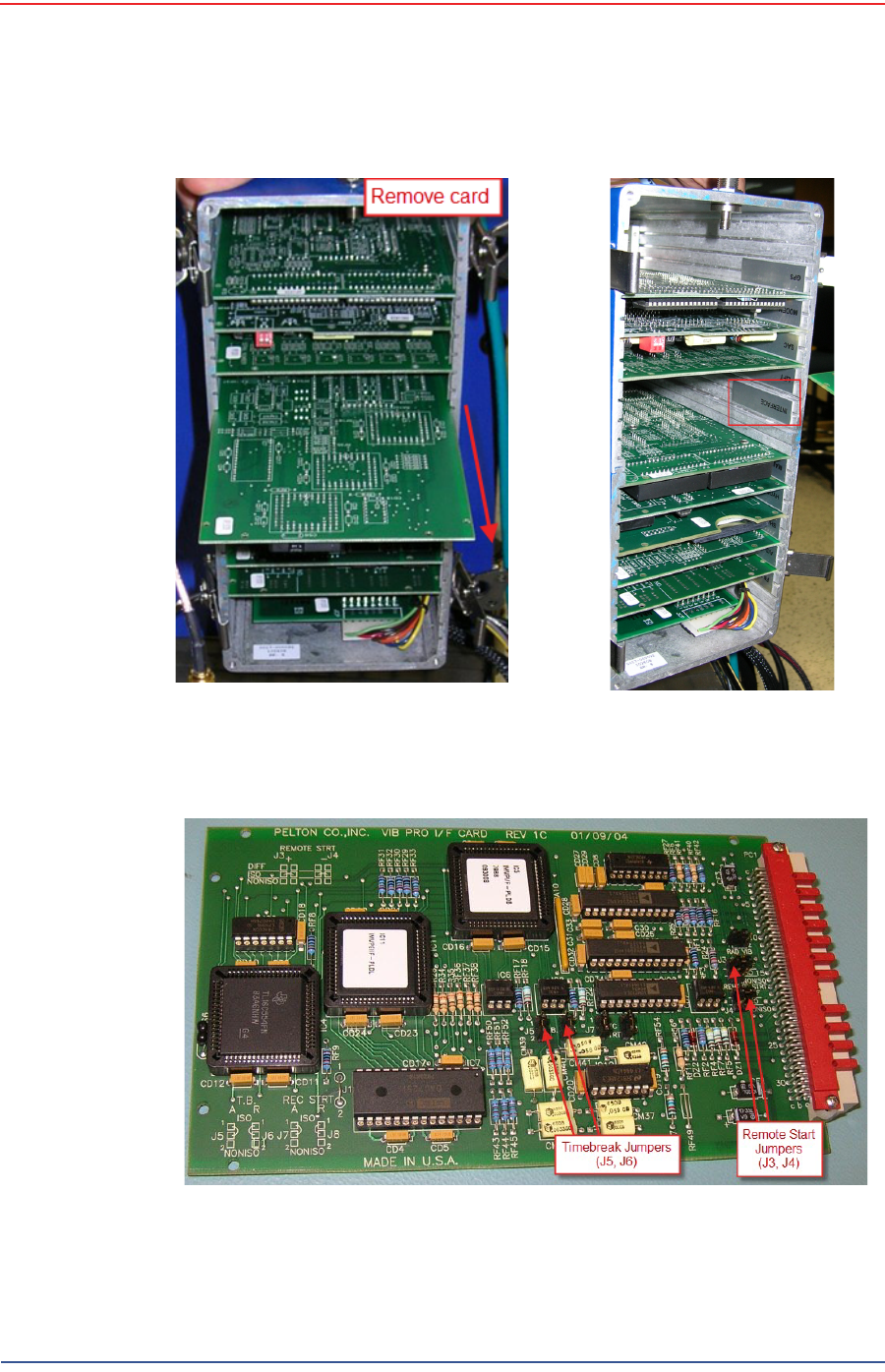
2Open the back of the Vib Pro and remove the interface card. Use proper anti-
static precautions.Refer to the Pelton documentation as necessary.
NOTE
Detailed instructions on using the Pelton Vib Pro are beyond the scope
of this document.
5Mbps Draft
R03.h RT 1000 1.5.0 Deployment Guide 15
© 2010-2012 Wireless Seismic, Inc. All rights reserved.
2. Layout
Setting Up the Central Recording System
Figure 2–1 Pelton Vib Pro Interface Card in Slot
Figure 2–2 Pelton Vib Pro Interface Card
5Mbps Draft
16 RT 1000 1.5.0 Deployment Guide R03.h
© 2010-2012 Wireless Seismic, Inc. All rights reserved.
2. Layout
Setting Up the Central Recording System
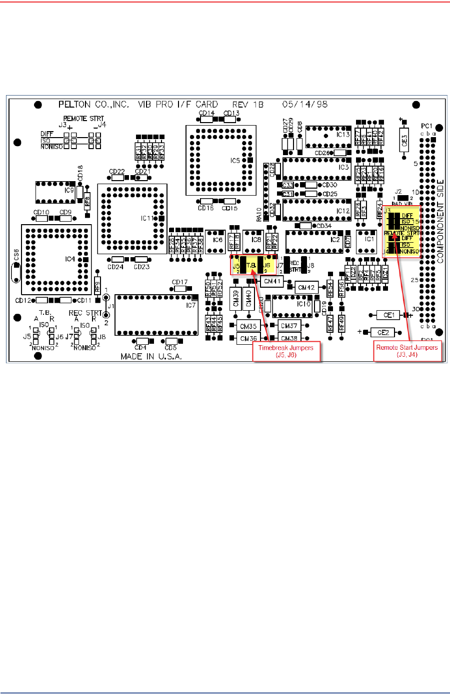
3Connect the Timebreak and Remote Start jumpers as shown in the following
figure:
Figure 2–3 Pelton Vib Pro Interface Card Assembly Drawing
5Mbps Draft
R03.h RT 1000 1.5.0 Deployment Guide 17
© 2010-2012 Wireless Seismic, Inc. All rights reserved.
2. Layout
Setting Up the Central Recording System
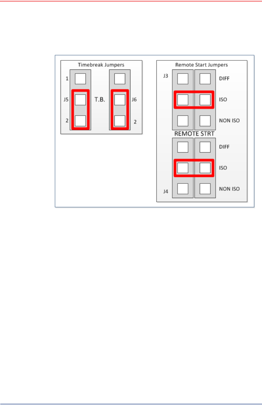
4Slide the interface card into the Pelton Vib Pro and close the case.
5Connect the Pelton analog output (JF: 27-pin connector) to the WRU’s analog
input (geophone connector) as shown in the following figures:
Figure 2–4 Pelton Vib Pro Jumpers
5Mbps Draft
18 RT 1000 1.5.0 Deployment Guide R03.h
© 2010-2012 Wireless Seismic, Inc. All rights reserved.
2. Layout
Setting Up the Central Recording System
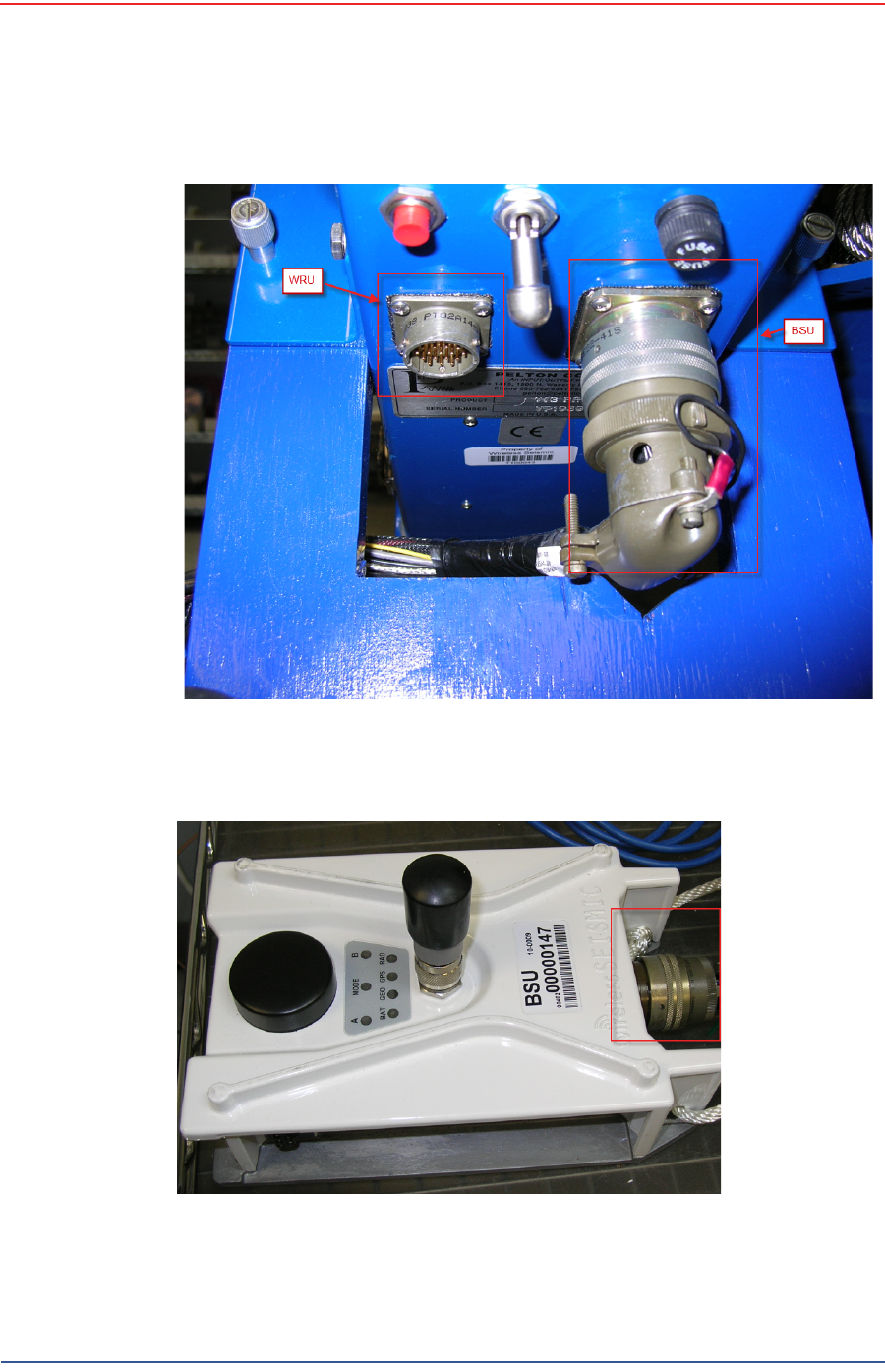
Figure 2–5 Pelton Analog Output Connection
Figure 2–6 BSU Analog Input Connection
5Mbps Draft
R03.h RT 1000 1.5.0 Deployment Guide 19
© 2010-2012 Wireless Seismic, Inc. All rights reserved.
2. Layout
Setting Up the Central Recording System
6Connect the Pelton Vib Pro JE Connector to the WRU analog input (geophone
connector).
7Power on the Pelton Vib Pro.
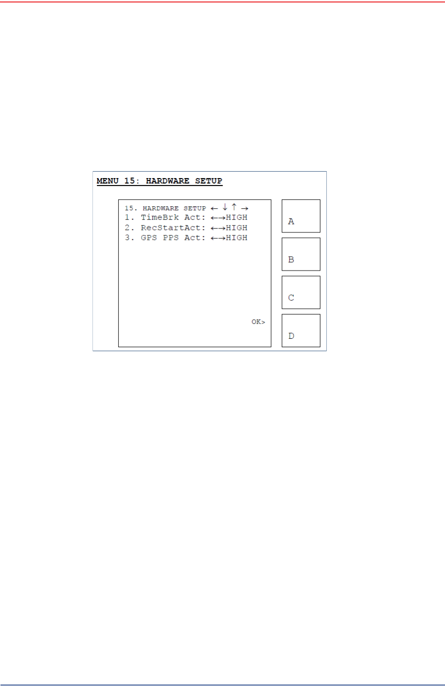
8Set TimeBrk Act=LOW
(Start → Menu (B) → MORE → 15. HARDWARE SETUP → 1. TimeBrk Act :
HIGH).
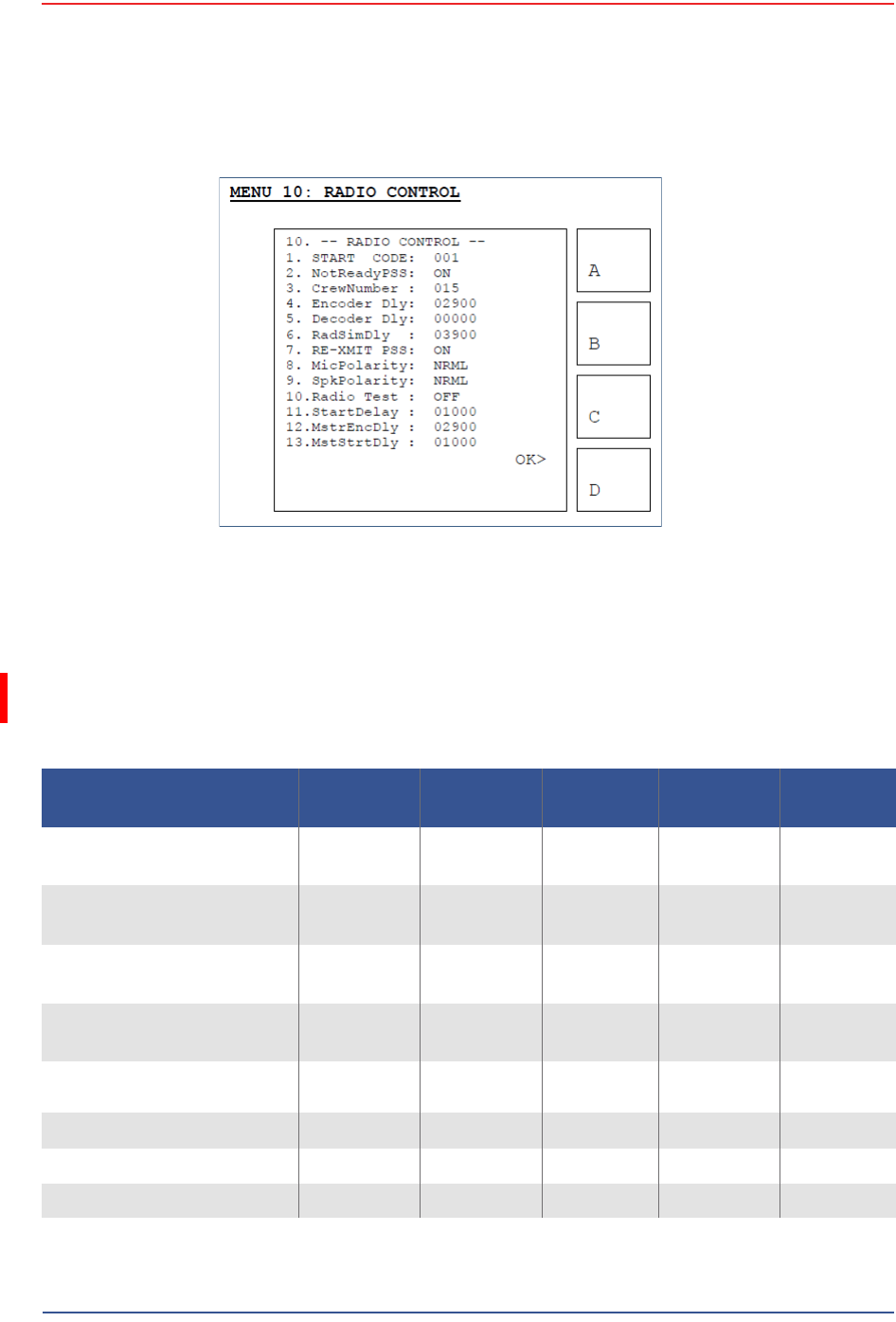
9Set the Start Delay=1000
(Start → Menu (B) → MORE → 10. RADIO → 11. StartDelay : 01000).
Figure 2–7 Pelton Vib Pro TimeBrk Act
5Mbps Draft
20 RT 1000 1.5.0 Deployment Guide R03.h
© 2010-2012 Wireless Seismic, Inc. All rights reserved.
2. Layout
Setting Up the Central Recording System
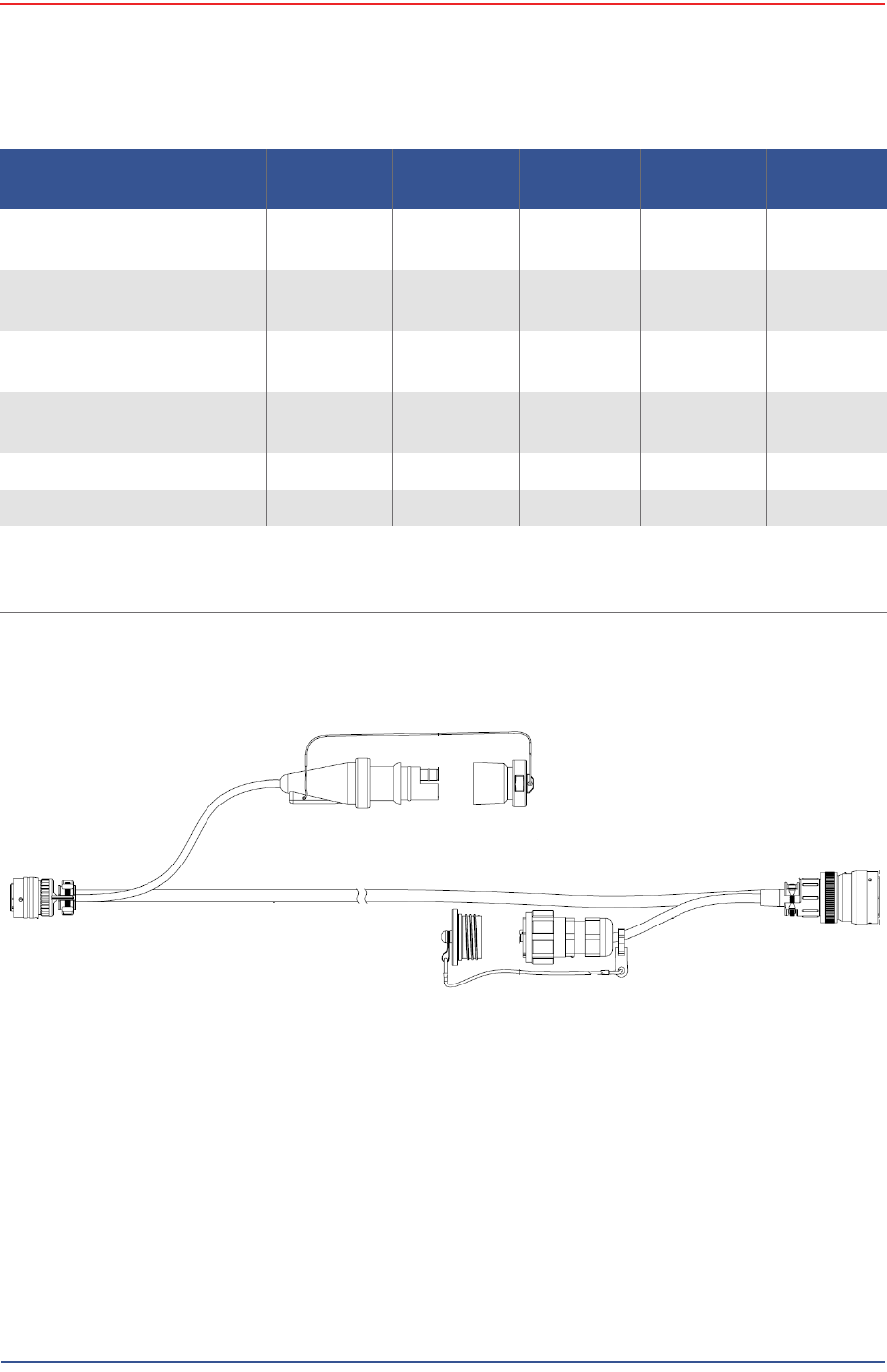
2.4.3 Source Interface Cables
The following table and figure show the cable used to connect the Pelton Vib Pro to
the BSU and WRU.
Figure 2–8 Pelton Vib Pro StartDelay
Table 2–1 PELTON SOURCE CONTROL (60-0015) Cable Pin List
Signal Name Wire Color 27-Pin
Connector RJ45 Plug 18-Pin
Connector 2-Pin
Connector
TX+ WHT/ORG *
(WHT/GRN) R1——
TX- ORG *
(GRN) P 2 — —
RX+ WHT/GRN *
(WHT/ORG) N3——
RX- GRN *
(ORG) M 6 — —
5V EXTERNAL NON ISO
START BLU B — J —
EXTERNAL START RETURN GRN A — K —
5V TRIGGER IN 1 BRN K — G —
TRIGGER 1 RETURN WHT X — H —
5Mbps Draft
R03.h RT 1000 1.5.0 Deployment Guide 21
© 2010-2012 Wireless Seismic, Inc. All rights reserved.
2. Layout
Setting Up the Central Recording System
PWR WHT/BLU
(WHT/BLU) b5——
PWR BLU
(BLU) c 4 — —
GND WHT/BRN
(WHT/BRN) a7——
GND BRN
(BRN) d 8 — —
INPUT + RED — — — N
INPUT - BLU — — — U or A
WHT = White, ORG = Orange, GRN = Green, BLU = Blue, BRN = Brown, BLK= Black, YEL = Yellow
* Connect per Pin Numbers
Wire colors in parenthesis are for Ethernet cable wired per T-586A standard.
Table 2–1 PELTON SOURCE CONTROL (60-0015) Cable Pin List (cont.)
Signal Name Wire Color 27-Pin
Connector RJ45 Plug 18-Pin
Connector 2-Pin
Connector
Figure 2–9 PELTON SOURCE CONTROL (60-0015) Cable

5Mbps Draft
22 RT 1000 1.5.0 Deployment Guide R03.h
© 2010-2012 Wireless Seismic, Inc. All rights reserved.
2. Layout
Setting Up the Central Recording System
2.4.4 Trigger Pin-Outs
The following tables show the signals on each pin for the three possible cables
used to connect a trigger to the CSS computer:
The following cable (60-0004) has not yet been implemented.
Table 2–2 BSU DATA-POWER (60-0007) Cable Pin List
Signal Name Wire Color 27-Pin
Connector Twisted
Pair
TX+ WHT/ORG *
(WHT/GRN) R
Twisted Pair
TX- ORG *
(GRN) P
RX+ WHT/GRN *
(WHT/ORG) N
Twisted Pair
RX- GRN *
(ORG) M
5V EXTERNAL NON ISO START RED B
Twisted Pair
EXTERNAL START RETURN BLK A
EXT START ISO OUT BLU E
Twisted Pair
EXT START ISO RETURN BLK U
5V TRIGGER IN 1 RED K
Twisted Pair
TRIGGER 1 RETURN WHT X
PWR RED b
PWR RED c
GND BLK a
GND BLK d
WHT = White, ORG = Orange, GRN = Green, BLU = Blue, BRN = Brown, BLK= Black,
YEL = Yellow
* Connect per Pin Numbers
Wire colors in parenthesis are for Ethernet cable wired per T-586A standard.

5Mbps Draft
R03.h RT 1000 1.5.0 Deployment Guide 23
© 2010-2012 Wireless Seismic, Inc. All rights reserved.
2. Layout
Setting Up the Central Recording System
Table 2–3 SIU Source Control (60-0004) Cable Pin List
Signal Name Wire Color 27-Pin
Connector
5V0 EXTERNAL START RED B
EXT. START RETURN BLK A
RS232 TX OUT WHT C
RX/TX RETURNS BLK S
RS232 RX IN GRN D
RX/TX RETURNS BLK T
EXT START ISO OUT BLU E
EXT START ISO RETURN BLK U
GND DIG (JUMPTRACK NO) YEL F
GND DIG (JUMPTRACK NO) BLK G
5V0 TRIGGER IN 3 BRN H
TRIGGER RETURN BLK V
5V0 TRIGGER IN 2 ORG J
TRIGGER RETURN BLK W
5V0 TRIGGER IN 1 RED K
TRIGGER RETURN WHT X
——L
TX+ WHT/ORG*
(WHT/GRN) R
TXN ORG*
(GRN/WHT) P
RX+ WHT/GRN*
(WHT/ORG) N
RXY GRN*
(ORG/WHT) M
— — Y
——Z
PWR RED c
PWR RED b

5Mbps Draft
24 RT 1000 1.5.0 Deployment Guide R03.h
© 2010-2012 Wireless Seismic, Inc. All rights reserved.
2. Layout
Setting Up the Central Recording System
The following cable (60-0012) has not yet been implemented.
GND BLK a
GND BLK d
WHT = White, ORG = Orange, GRN = Green, BLU = Blue, BRN = Brown, BLK=
Black, YEL = Yellow
* Connect per Pin Numbers
Wire colors in parenthesis are for Ethernet cable wired per T-586A standard.
Table 2–4 BSU at Recording Truck (60-0012) Cable Pin List
Signal Name Wire Color 27-Pin
Connector
TX+ WHT/ORG *
(WHT/GRN) R
TX- ORG *
(GRN/WHT) P
RX+ WHT/GRN *
(WHT/ORG) N
RX- GRN *
(ORG/WHT) M
PWR WHT/BLU
(WHT/BLU) b
PWR BLU
(BLU) c
GND WHT/BRN
(WHT/BRN) a
GND BRN
(BRN) d
Free Leads
5V EXTERNAL NON ISO START BLU B
RETURN EXTERNAL NON ISO START GRN A
5V TRIGGER IN 1 BRN K
TRIGGER 1 RETURN WHT X
Table 2–3 SIU Source Control (60-0004) Cable Pin List (cont.)
Signal Name Wire Color 27-Pin
Connector

5Mbps Draft
R03.h RT 1000 1.5.0 Deployment Guide 25
© 2010-2012 Wireless Seismic, Inc. All rights reserved.
2. Layout
Laying Out the Equipment
2.5 Laying Out the Equipment
You can lay out the ground equipment while the central recording system
hardware and software is being prepared.
The WRU is shown in the following figure:
The BSU is shown in the following figure:
An example geophone is shown in the following figure
2.5.1 Prerequisites
You can attach the batteries, antennas, and geophones to the ground equipment
prior to going into to the field, or as you place each unit. If you are assembling as
you place the units, ensure that you have sufficient quantities for each unit, plus a
few spares.
The RT 1000 shall be used with only the supplied antennas (Table A–1 Antenna
Specifications, on page 90) attached to the WRU with an integrated type N male
connector.
The RT 1000 antennas shall be installed and handled by professionals
specifically designated for this purpose.
Changes or modifications not expressly approved by Wireless Seismic, Inc. can
void the users’s authority to operate the equipment.
WHT = White, ORG = Orange, GRN = Green, BLU = Blue, BRN = Brown, BLK= Black,
YEL = Yellow
* Connect per Pin Numbers
Wire colors in parenthesis are for Ethernet cable wired per T-586A standard.
Table 2–4 BSU at Recording Truck (60-0012) Cable Pin List (cont.)
Signal Name Wire Color 27-Pin
Connector
Illustration TBD
Figure 2–10 WRU
Illustration TBD
Figure 2–11 BSU
Illustration TBD
Figure 2–12 Geophone

5Mbps Draft
26 RT 1000 1.5.0 Deployment Guide R03.h
© 2010-2012 Wireless Seismic, Inc. All rights reserved.
2. Layout
Laying Out the Equipment
2.5.2 Assembling the Ground Equipment
This section describes the process to assemble the ground equipment prior to
deployment.
To assemble the ground equipment:
1Gather the equipment:
●WRU or BSU
●Antenna
●Geophone
●Batteries
2Gather any special tools:
●Optional: Nylon grip pliers
●Optional: Loctite® 222
3Attach one or more batteries to the WRU.
●Press the battery into the connector.
●Flip the bail over the molded area on the end of the battery.
●Press the lever until the catch snaps to lock it in place.
WARNING
In order to comply with FCC radio frequency (RF) exposure
requirements, the RT 1000 units must be installed so that a minimum
separation distance of 20 cm is maintained between the antenna(s) and
all persons at all times during normal operation.
WARNING
AVERTISSE
MENT
Afin de se conformer aux normes de la FCC en matière d'exposition aux
radiofréquences (RF), les unités RT 1000 doivent être installées de
manière à garder en permanence une distance minimale de 20 cm entre
la ou les antennes et toute personne en mode de fonctionnement
normal.

5Mbps Draft
R03.h RT 1000 1.5.0 Deployment Guide 27
© 2010-2012 Wireless Seismic, Inc. All rights reserved.
2. Layout
Laying Out the Equipment
4Attach the geophone to the WRU.
Figure 2–13 Battery Latch
Figure 2–14 Installing the Battery

5Mbps Draft
28 RT 1000 1.5.0 Deployment Guide R03.h
© 2010-2012 Wireless Seismic, Inc. All rights reserved.
2. Layout
Laying Out the Equipment
5Attach the antenna to the WRU or BSU. Ensure that the antenna connection is
clean, and the antenna is snug and does not wobble.
2.5.3 Placing the WRU in the Field
This section describes the process to ready the ground equipment for interaction
with the central recording system (deployment).
To deploy the WRU:
1Prerequisites:
●The WRU is assembled with battery, geophone, and antenna
Figure 2–15 Installing the
Geophone
TBD
Figure 2–16 Installing the Antenna
TIP
When determining which antenna to use (5 dBi, 7 dBi, 9dBi), consider
the distance between WRUs, and how much vegetation is in the area.
For distances of 10 m to 30 m, use a 5 dBi antenna.
Distances of 30 m or greater, use a 7 dBi antenna.
For sudden elevation changes, such as cliffs, use a 2 dBi or 5 dBi
antenna.
In special situations such as tall grass and dense vegetation, or
distances of 55 m or greater, use a 9 dBi antenna.
5Mbps Draft
R03.h RT 1000 1.5.0 Deployment Guide 29
© 2010-2012 Wireless Seismic, Inc. All rights reserved.
2. Layout
Laying Out the Equipment
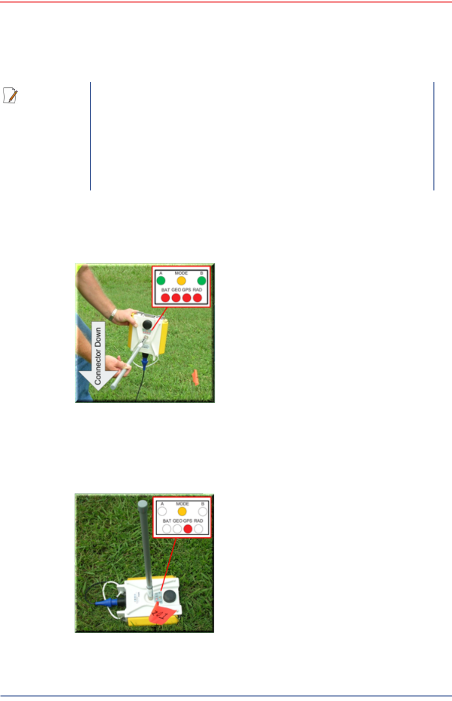
2Pick up the WRU and point the geophone connector end towards the ground as
shown in the following figure. After a few seconds, all of the LEDs illuminate:
3Place the unit flat on the ground as shown in the following figure:
NOTE
If you are using a WRU as a Repeater, the deployment instructions are
the same, except a geophone is not required. Repeaters are added to
the line segment in the Spread Manager. See the RT 1000 Operator
Guide for more information.
If a geophone is not connected, you can skip the geophone test. See
“D. LED Indicators” on page 100 for more information on skipping the
test and the relevant LED status indicators.
Figure 2–17 Power on the
Unit
Figure 2–18 Place the Unit

5Mbps Draft
30 RT 1000 1.5.0 Deployment Guide R03.h
© 2010-2012 Wireless Seismic, Inc. All rights reserved.
2. Layout
Laying Out the Equipment
4The unit will begin a series of internal and external tests. The LEDs on the top
of the unit indicate the current test and whether the unit passes or fails each
test.
2.5.4 Placing the BSU in the Field
The BSU is part of the backhaul configuration. See “3. Backhaul” on page 31 for
more information.
NOTE
See “D. LED Indicators” on page 100 for an explanation of the LED
status and error conditions.
If a WRU self test fails, the WRU will continue to the next test.
You can skip a self-test by tipping the WRU geophone down and then
returning it to the upright position (flat on the ground).

5Mbps Draft
RT 1000 1.5.0 31 Deployment Guide R03.h
© 2010-2012 Wireless Seismic, Inc. All rights reserved.
3
3. Backhaul
3.1 Overview
In network communications, the backhaul is the part of the network that
contains the links and equipment between the core network and the sub
networks.
Wireless mesh networking is a method where each radio node in the network
captures and disseminates its own data as well as serves as a relay for other
radio nodes in the network sending data along a path, hopping from one node
to the next.
Power over Ethernet (PoE) is a technology that passes electrical power along
an Ethernet cable. PoE is used where DC power is not available and USB
unsuitable. Power can be supplied at the end of a network span or somewhere
in the middle. PoE switches supply power at the end of a span. PoE injectors
supply power somewhere between the PoE switch and the powered device.
They inject power and do not affect the data.
The RT 1000 Central Recording System is a fully connected mesh network of
Wireless Remote Units (WRUs) that communicate in a relay pattern (bucket-
brigade or string-of-pearls) with a Line Tap Unit (LTU) on the 2.4 GHz
Industrial, Scientific, and Medical (ISM) radio band.
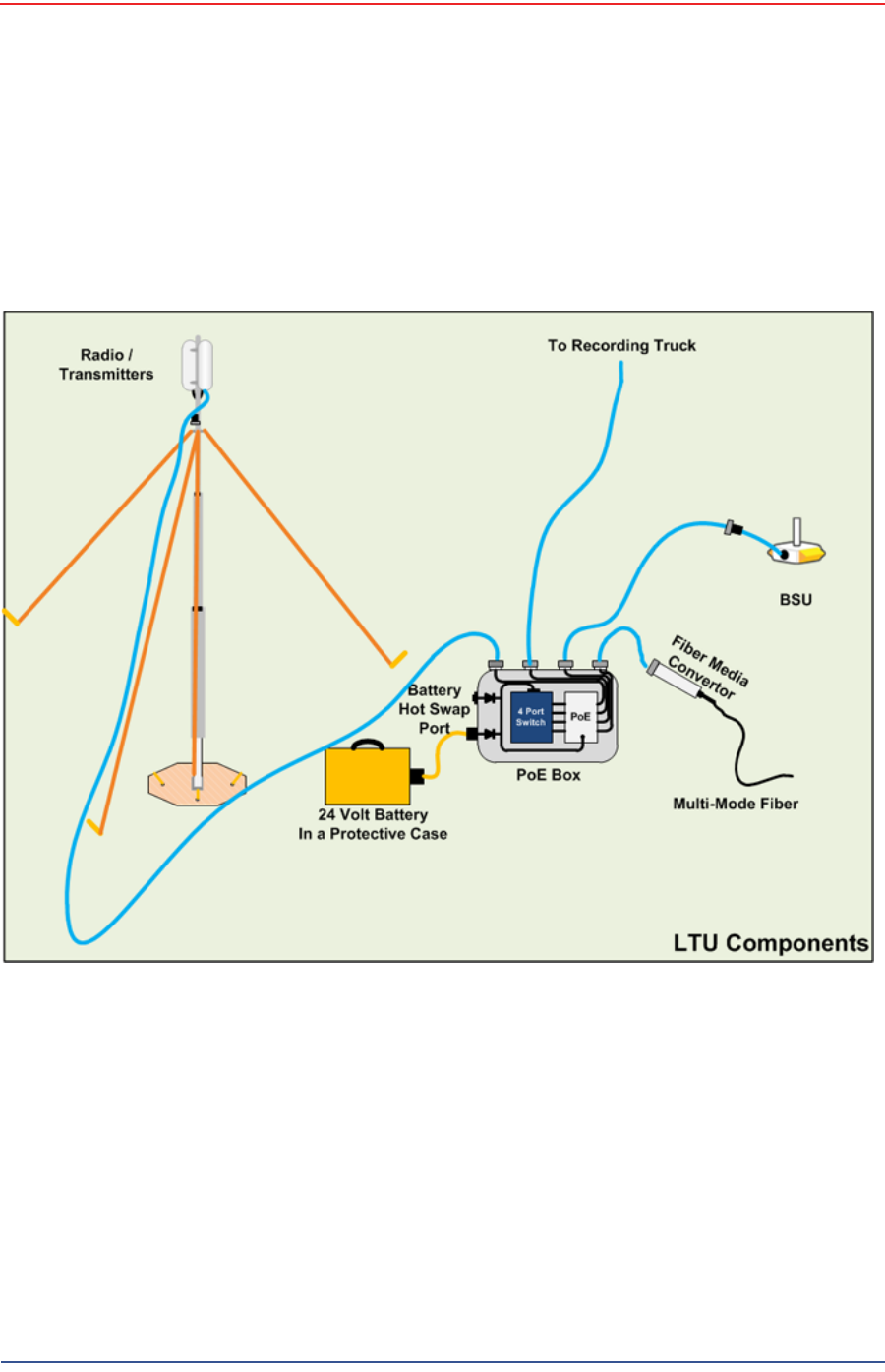
The LTU is composed of the following:
Base Station Unit (BSU)
Power over Ethernet (PoE)
24 Ah DC Battery or Power Supply
Cables
Mast, mast base, and guy-wires
5.8 GHz backhaul radios
Antennas
CAUTION
Ensure that the PoE box is placed on the ground, or that a grounding
cable is attached to avoid causing damage to the internal electronics
during use.
5Mbps Draft
32 RT 1000 1.5.0 Deployment Guide R03.h
© 2010-2012 Wireless Seismic, Inc. All rights reserved.
3. Backhaul
Overview
The LTU communicates by way of the BSU with the Central Software System (CSS)
computer in the central recording truck along a backhaul on the 5.8 GHz ISM radio
band. Some smaller systems may not require a backhaul.
The Central Software System (CSS) communicates with the field units via the
backhaul radios. The backhaul radios act as access points for the BSUs.
The following figure illustrates the possible LTU components:
Figure 3–1 Possible LTU Components
5Mbps Draft
R03.h RT 1000 1.5.0 Deployment Guide 33
© 2010-2012 Wireless Seismic, Inc. All rights reserved.
3. Backhaul
Overview
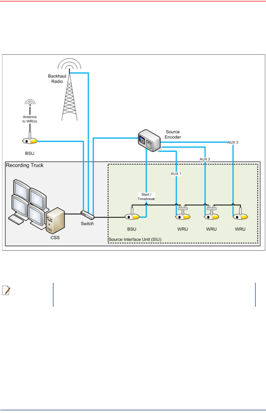
The following figure illustrates the central recording truck components:
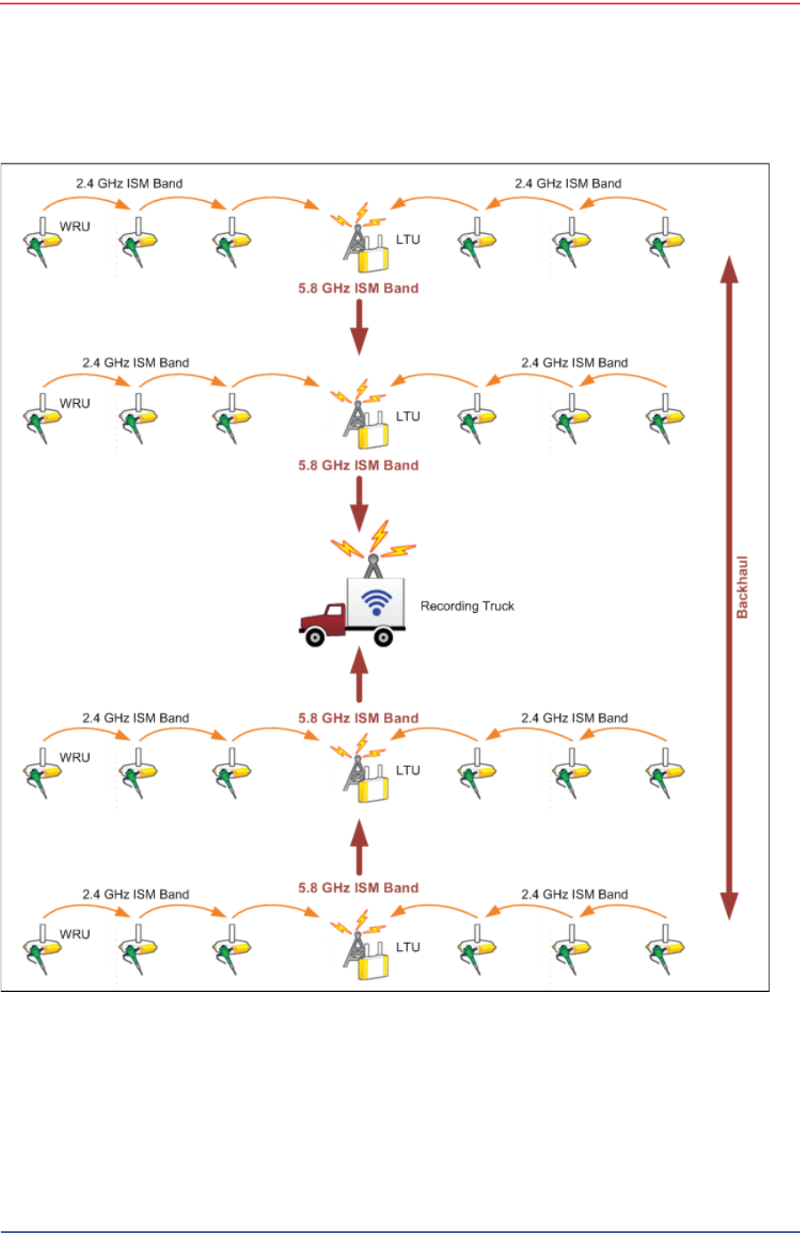
The following figure illustrates the components and data flow for a four-line,
single-backhaul line with two root nodes example:
Figure 3–2 Central Recording Truck Components
NOTE
There can be from one to three WRUs in the Recording Truck as part of
the SIU.
5Mbps Draft
34 RT 1000 1.5.0 Deployment Guide R03.h
© 2010-2012 Wireless Seismic, Inc. All rights reserved.
3. Backhaul
Overview
Figure 3–3 Single Backhaul Data Direction

5Mbps Draft
R03.h RT 1000 1.5.0 Deployment Guide 35
© 2010-2012 Wireless Seismic, Inc. All rights reserved.
3. Backhaul
Backhaul Components
3.2 Backhaul Components
The backhaul components are either remote backhaul components or central
backhaul components. Remote components are the components that are not
physically located next to the recording truck. Central components are physically
located at the recording truck. Both remote and central backhauls are composed of
the following:
Base Station Unit (BSU) Kit
Antenna
Radio Kit
Mast Kit
The following figure shows the backhaul components packed for transport:
3.2.1 BSU Components
The following table lists the BSU kit components:
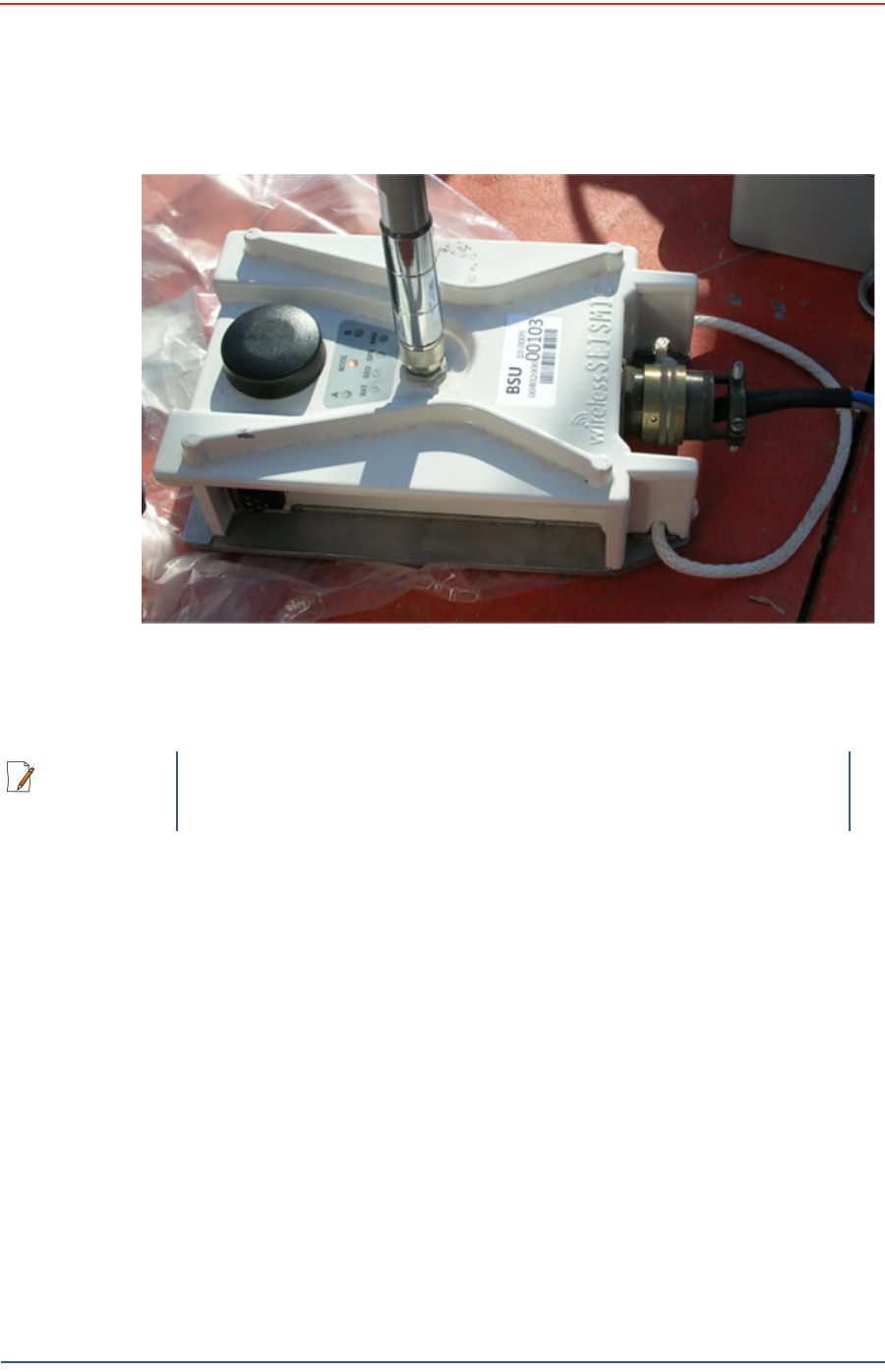
3.2.1.1 BSU
The Base Station Unit (BSU) is shown in the following figure:
TBD
Figure 3–4 Backhaul Components Packed for Transport
Table 3–1 Base Station Unit Kit
Remote Backhaul Components Central Backhaul Components
Item Reference Item Reference
BSU (10-0009) “BSU” on page
35 BSU (10-0009) “BSU” on page
35
PoE Switch Unit (10-0012) “PoE Switch
Unit” on page
36
PoE Switch Unit (10-0012) “PoE Switch
Unit” on page
36
Battery (10-0015) “Battery and
Power Supply”
on page 37
Power Supply, 24 V (75-0017) “Battery and
Power Supply”
on page 37
Cable Assembly, BSU-to-PoE
Switch (60-0008) “Cables” on
page 38 Cable Assembly, BSU at truck
(60-0012) “Cables” on
page 38
Cable, PoE Switch-to-Battery
(60-0011) “Cables” on
page 38 Cable, Power Supply-to-PoE
(# TBD) “Cables” on
page 38
Ethernet Cable, 25 ft (65-
0046) “Cables” on
page 38
5Mbps Draft
36 RT 1000 1.5.0 Deployment Guide R03.h
© 2010-2012 Wireless Seismic, Inc. All rights reserved.
3. Backhaul
Backhaul Components
Before the Central Software System can communicate with the BSU, you must set
up the backhaul.
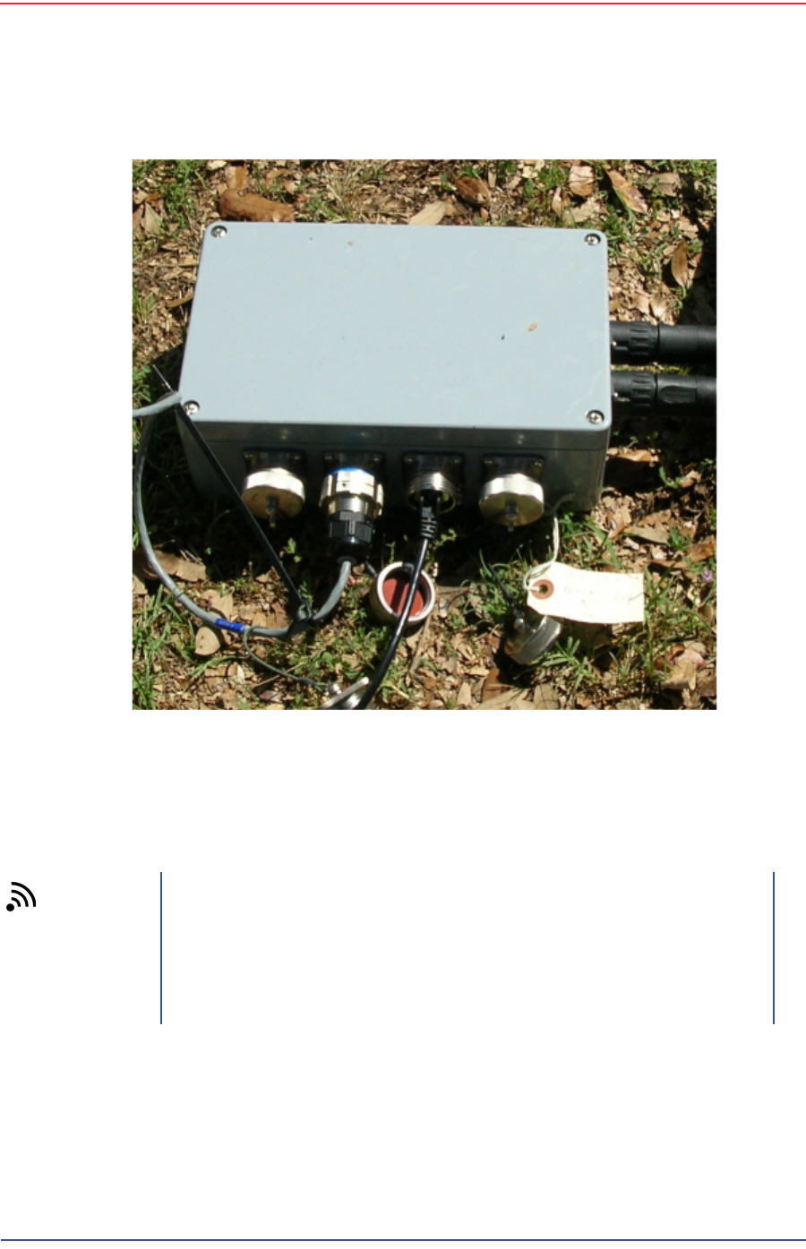
3.2.1.2 PoE Switch Unit
Power over Ethernet (PoE) is a technology that passes electrical power along an
Ethernet cable. PoE is used where DC power is not available and USB unsuitable.
Power can be supplied at the end of a network span or somewhere in the middle.
PoE switches supply power at the end of a span. PoE injectors supply power
somewhere between the PoE switch and the powered device. They inject power
and do not affect the data.
The PoE is shown in the following figure:
Figure 3–5 Base Station Unit (BSU)
NOTE
See “D. LED Indicators” on page 100 for an explanation of the LED
status and error conditions.
5Mbps Draft
R03.h RT 1000 1.5.0 Deployment Guide 37
© 2010-2012 Wireless Seismic, Inc. All rights reserved.
3. Backhaul
Backhaul Components
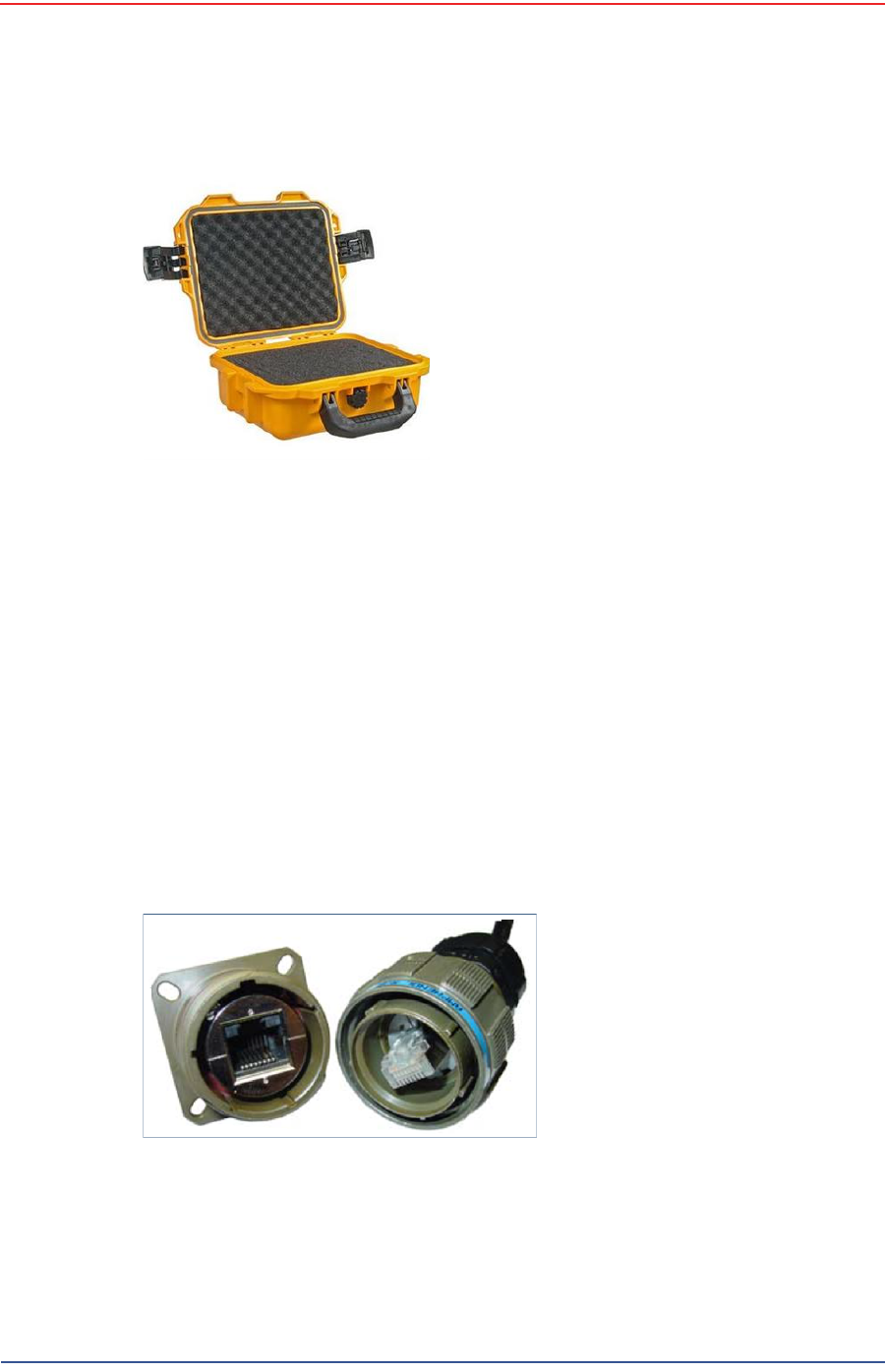
3.2.1.3 Battery and Power Supply
Power is supplied to the LTU components by way of a 24 Ah DC battery or power
supply.
Wireless Seismic, Inc. recommends using a protective battery case as shown in
the following figure:
Figure 3–6 PoE
TIP
The backhaul power requirements vary depending on the hardware in
use and period of use. For example, you may be using one or two
radios. Supply enough power to ensure there is enough power for the
entire duration of the time you are using the backhaul.
A 24 Ah battery is adequate if a recharged battery is installed for every
12 hours of use.
5Mbps Draft
38 RT 1000 1.5.0 Deployment Guide R03.h
© 2010-2012 Wireless Seismic, Inc. All rights reserved.
3. Backhaul
Backhaul Components
3.2.1.4 Cables
The following cables are used in the backhaul:
BSU-to-PoE Switch 27-pin to RJ45 (60-0008)
BSU at Recording Truck 27-pin to RJ45 (60-0012)
PoE Switch-to-Battery 2-pin to 2-pin (60-0011)
Power Supply-to-PoE (# TBD)
Ethernet Cable, 25 ft (65-0046)
TBD – Fiber Optic Cable
To ensure a protected connection, be sure to use an Ethernet cable with a
protective shell (65-0051) when connecting Ethernet cables to the PoE. An
example is shown in the following figure:
Figure 3–7 Protective Battery
Case
Figure 3–8 Protective Ethernet
Connector

5Mbps Draft
R03.h RT 1000 1.5.0 Deployment Guide 39
© 2010-2012 Wireless Seismic, Inc. All rights reserved.
3. Backhaul
Backhaul Components
3.2.2 Antennas
The following table lists the supported antennas for the BSUs and the WRUs. The
remote and central backhauls use the same antennas:
The Fluidmesh radios have built-in antennas (see “Radio Kit Components” on page
39 for details).
There is an auto-power-leveling feature built into the firmware. It works in
conjunction with the RSSI parameters to keep the power at a defined level.
3.2.3 Radio Kit Components
The following table lists the Radio Kit components:
Refer to the Fluidmesh datasheet for FCC information and other technical
specifications on the FM1100 and FM3100 radios. See one of the following
locations for details:
http://www.fluidmesh.com/press-room/product-literature/doc_details/160-
fluidmesh-mito-series
“C. Fluidmesh Radio Specifications” on page 94
The Fluidmesh radios can operate on at 4.9 GHz, and 5.1 - 5.8 GHz. The preferred
frequency is configured through a user interface (see “Configure the Radios” on
page 46 for instructions).
Table 3–2 Antenna Specifications
Model Frequency
(MHz) Gain Vertical
Bandwidth Weight Dimension
(Length x
Diameter)
WSI 65-0067 2400-2485 9 dbi 14° 0.8 lbs
0.5 kg 27 x 0.6 in
690 x 15 mm
WSI 6060-001-01 2400-2485 7 dBi 18° 0.6 lbs
0.3 kg 21 x 0.6 in
540 x 15 mm
WSI 65-0023 2400-2485 5 dBi 25º 0.5 lbs
0.2 kg 12 x 0.6 in
355 x 15 mm
WSI 65-0025 2400-2485 2 dBi @ 2.4 120° 1.6 oz
45.4 g 7.6 x 0.5 in
193 x 12.7 mm
Table 3–3 Radio Kit
Remote Backhaul Components Central Backhaul Components
Item Reference Item Reference
Radio, Fluidmesh® FM1100
(75-0014) “FM1100 Radio”
on page 40 Radio, Fluidmesh® FM3100
(75-0014) “FM1100 Radio”
on page 40
Software, Fluidmesh®
FM1100-30 (47-0006) “FM3100 Radio”
on page 41 Software, Fluidmesh®
FM3100-30 (47-00067) “FM3100 Radio”
on page 41
5Mbps Draft
40 RT 1000 1.5.0 Deployment Guide R03.h
© 2010-2012 Wireless Seismic, Inc. All rights reserved.
3. Backhaul
Backhaul Components
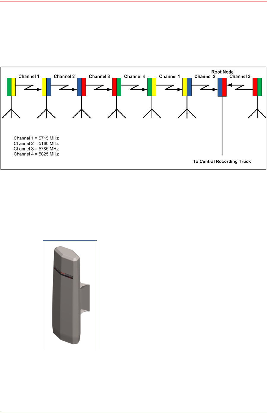
Each radio is assigned a color that represents the channel assignment, allowing
field personnel to quickly orient the radios in the proper direction. An example is
shown in the following figure:
The Fluidmesh default IP address is 192.168.0.10.
3.2.3.1 FM1100 Radio
The FM1100 radio is used on the masts for the remote backhauls and is shown in
the following figure:
Figure 3–9 Channel Color Example
Figure 3–10 FM1100
Radio