Wireless Seismic 00102 Wireless Remote Unit User Manual DeploymentGuide
Wireless Seismic, Inc. Wireless Remote Unit DeploymentGuide
Contents
- 1. Users Manual 1
- 2. Users Manual 2
Users Manual 2
5Mbps Draft
R03.h RT 1000 1.5.0 Deployment Guide 41
© 2010-2012 Wireless Seismic, Inc. All rights reserved.
3. Backhaul
Backhaul Components
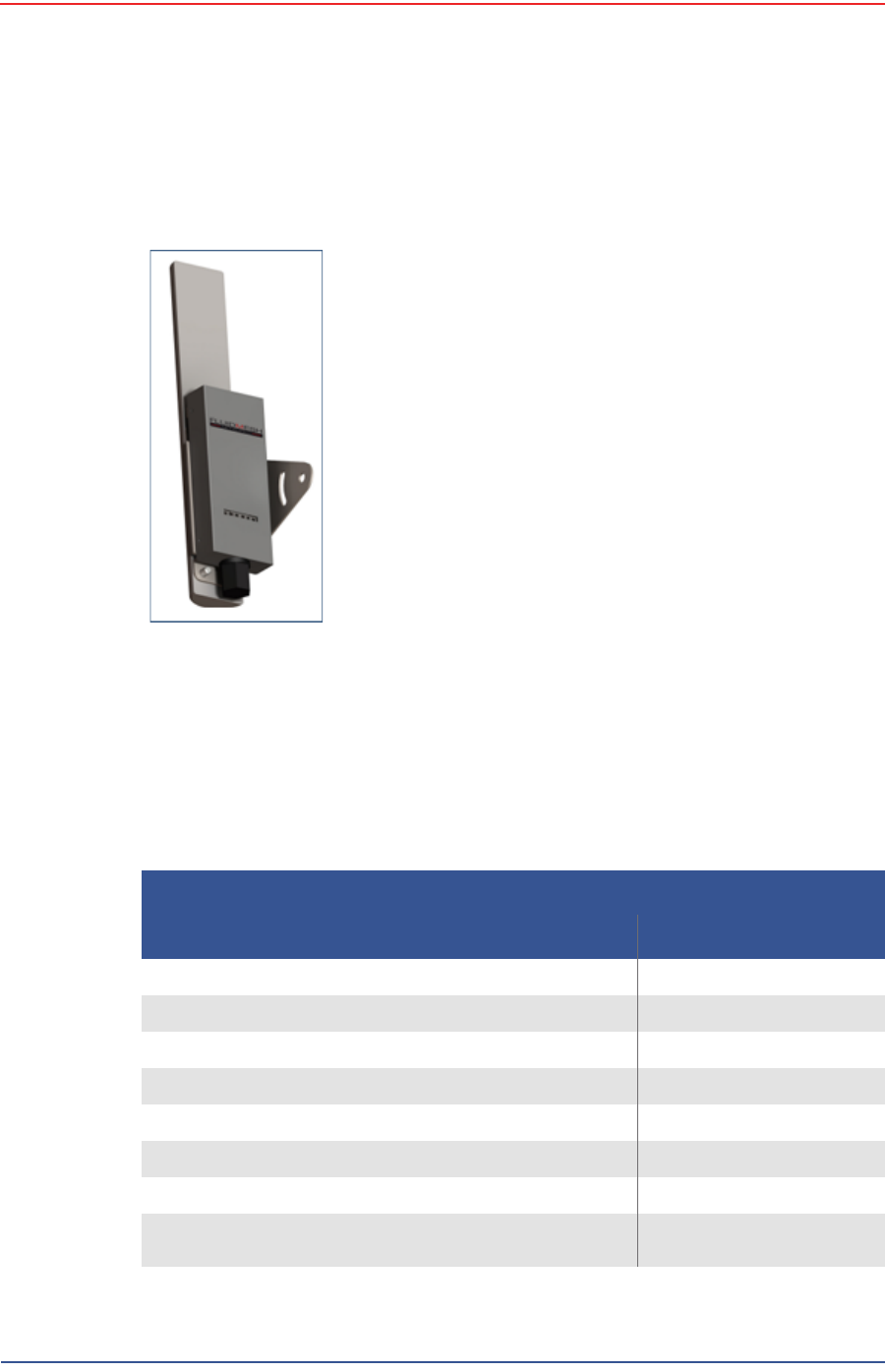
3.2.3.2 FM3100 Radio
The FM3100 is used on the masts for the central backhaul unit and is shown in the
following figure:
3.2.4 Mast Kit Components
The following table lists the Mast Kit components. The remote and central
backhauls use the same mast kit components:
Figure 3–11 FM3100
Radio
Table 3–4 Mast Kit
Remote Backhaul Components
Item Reference
Mast (55-0008) “Mast” on page 42
Base (55-0007) “Base” on page 42
Base, weighted (70-0070) “Base” on page 42
Bag (70-0058) “Bag” on page 45
Ethernet Cable, 25 ft (65-0046) (2 each) “Cables” on page 38
Backpack Kit (15-0014) “Backpack Kit” on page 45
• 1 each backpack (70-0059) “Backpack Kit” on page 45
• 3 each guy lines, rope, orange, 15.25 meters (70-
0057) “Backpack Kit” on page 45
5Mbps Draft
42 RT 1000 1.5.0 Deployment Guide R03.h
© 2010-2012 Wireless Seismic, Inc. All rights reserved.
3. Backhaul
Backhaul Components
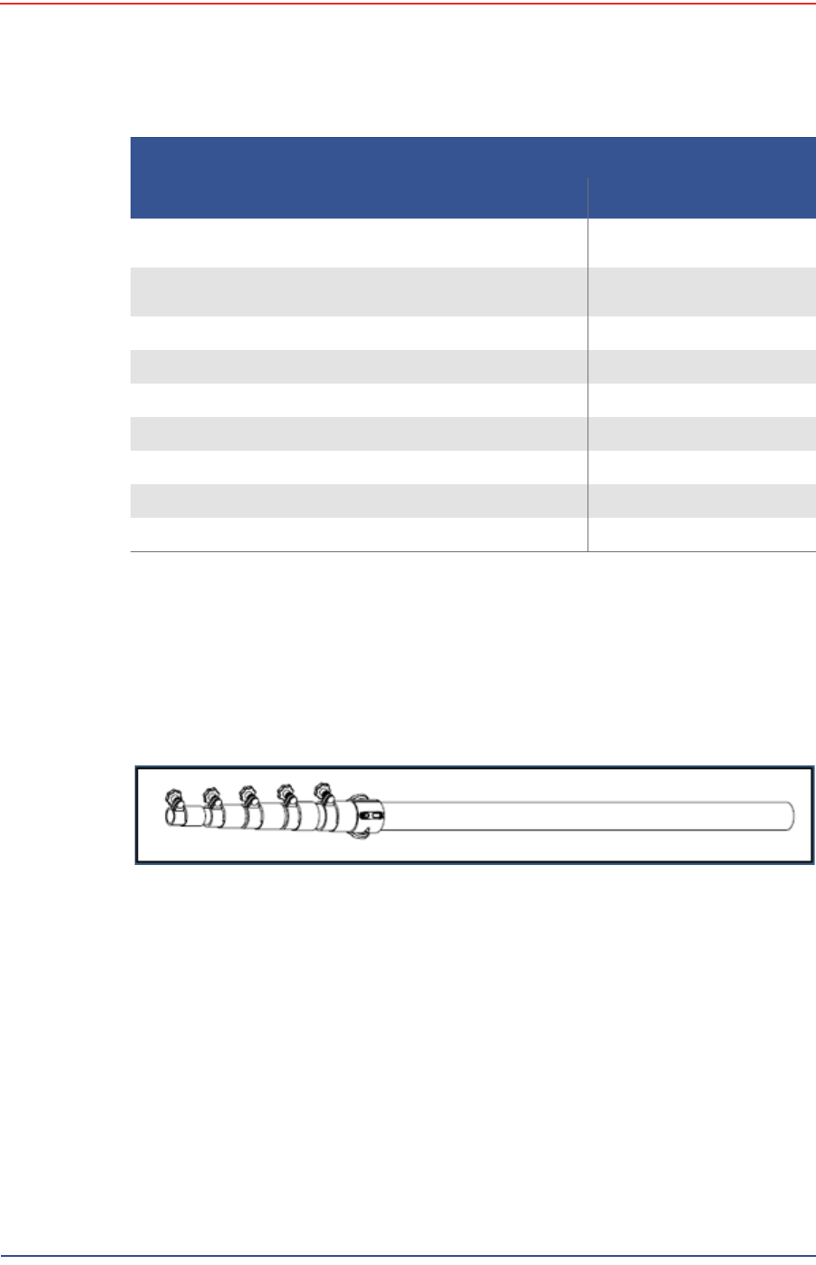
3.2.4.1 Mast
Lightweight, telescoping backhaul masts are used to elevate the backhaul
components above obstructions and to enable radio communications to
accommodate typical cross-line distances. The mast can be installed by a single
person. The following figures show the mast components:
3.2.4.2 Base
There are two base options; one that requires the use of guy wires for stabilization
and one that uses weights for stabilization.
• 3 each tent stake, steel, 12 in (70-0061) (hard
ground stakes) “Backpack Kit” on page 45
• 3 each tent stake, plastic, orange, 16 in (70-0060)
(soft ground stakes) “Backpack Kit” on page 45
• 5 ea nail, 12 in (70-0062) “Backpack Kit” on page 45
• 3 each guy line holder (70-0063) “Backpack Kit” on page 45
• 1 each hammer, 2.5 lb (70-0064) “Backpack Kit” on page 45
• 1 each pry bar, 15 in (70-0065) “Backpack Kit” on page 45
• 2 each flagging roll, orange (70-0066) “Backpack Kit” on page 45
• 1 each compass sighting (70-0067) “Backpack Kit” on page 45
• 5 each hose clamp, 2 in (70-0068) “Backpack Kit” on page 45
Figure 3–12 Mast (55-0008)
Table 3–4 Mast Kit (cont.)
Remote Backhaul Components
Item Reference

5Mbps Draft
R03.h RT 1000 1.5.0 Deployment Guide 43
© 2010-2012 Wireless Seismic, Inc. All rights reserved.
3. Backhaul
Backhaul Components
The following figures show the base that utilizes guy-wires:
Figure 3–13 Base (55-0007)
5Mbps Draft
44 RT 1000 1.5.0 Deployment Guide R03.h
© 2010-2012 Wireless Seismic, Inc. All rights reserved.
3. Backhaul
Backhaul Components
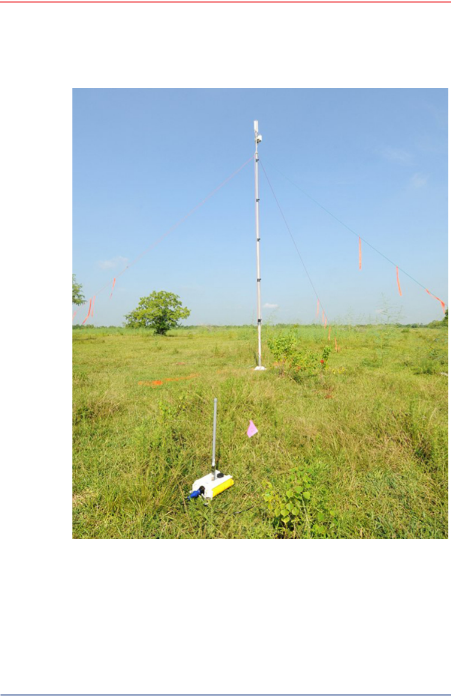
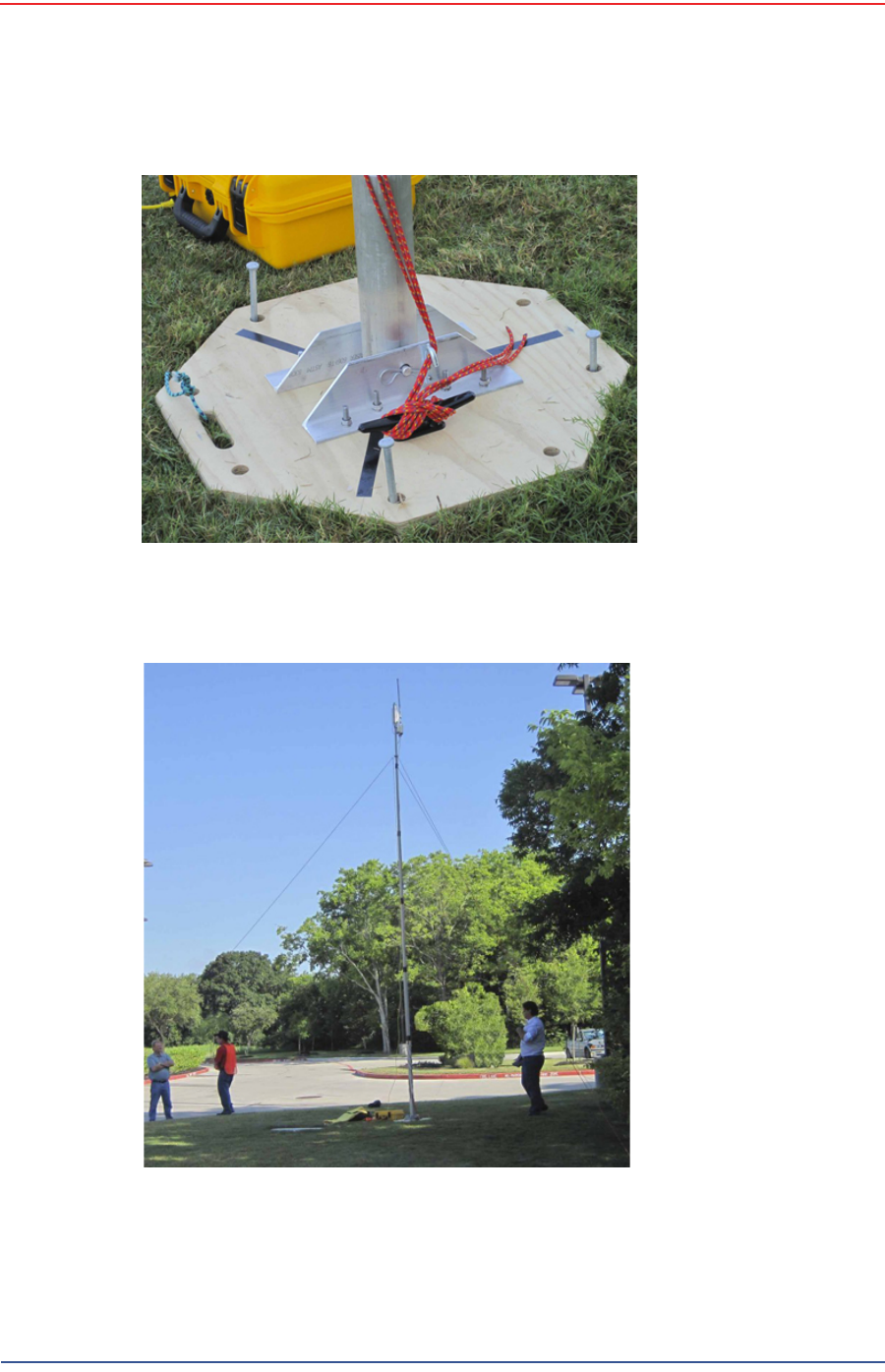
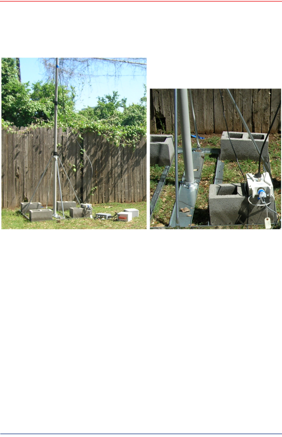
The following figure shows the assembled mast with the BSU in the foreground:
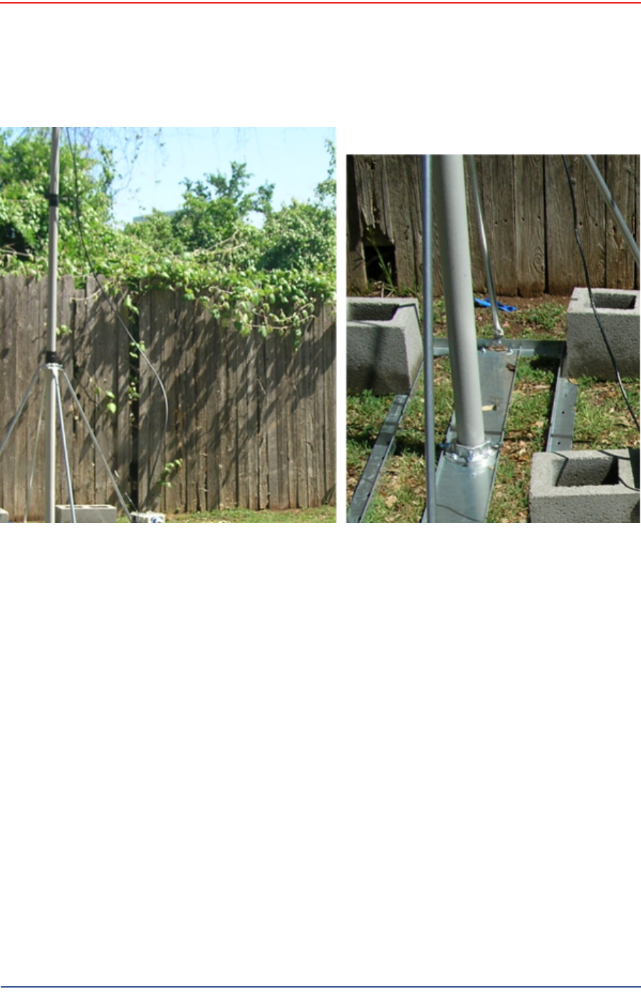
The following figure shows the base that uses a weighted system. This base is
optimal in urban or rocky environments:
Figure 3–14 Assembled Backhaul Mast
5Mbps Draft
R03.h RT 1000 1.5.0 Deployment Guide 45
© 2010-2012 Wireless Seismic, Inc. All rights reserved.
3. Backhaul
Backhaul Components
3.2.4.3 Bag
The antenna mast bag is a rip stop nylon yellow bag, 11 inches x 70 inches with a
handle and draw string at one end (see Figure 3–4 Backhaul Components Packed
for Transport on page 35).
3.2.4.4 Backpack Kit
The backpack is used to carry all of the equipment needed to install the mast and
radios, and may also be use to carry the BSU. See “Mast Kit” on page 41 for a list
of components (see Figure 3–4 Backhaul Components Packed for Transport on
page 35).
Figure 3–15 Base (70-0070)

5Mbps Draft
46 RT 1000 1.5.0 Deployment Guide R03.h
© 2010-2012 Wireless Seismic, Inc. All rights reserved.
3. Backhaul
Configure the Radios
3.3 Configure the Radios
The FMQuadro™ Web Interface is used to configure the radio channels. The radio
licenses are pre-configured by Wireless Seismic, Inc. This section describes how to
connect the radios to a computer and configure them.
Check the radios before connecting them to any switch.
3.3.1 Create a Private Network
Create a private network between the computer and the Fluidmesh radio.
1Prerequisites:
●Windows computer
●Browser with Adobe Flash
●AC Power
●PoE Injector
●Two Ethernet Cables
2Power on the computer.
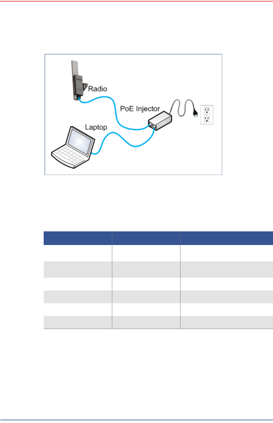
3Connect the components (see Figure 3–16 Fluidmesh Radio Private Network on
page 47):
●Plug the PoE injector into an AC outlet.
●Connect the computer to the PoE injector with an Ethernet cable.
●Connect the Fluidmesh radio to the PoE injector with an Ethernet cable. The
radio powers up.
►FM1100 – Connect to LAN 1
►FM3100 – There is only one connector
NOTE
The expected configuration in the RT 1000 system is as follows:
FM1100 = mesh point (remote backhaul)
FM3100 = mesh end (central backhaul)
NOTE
All Fluidmesh units are preconfigured with an IP address of
192.168.0.10.
CAUTION
Power up only one radio at a time. Never place two powered-up radios
next to each other. It is possible to damage the radio receivers if
multiple radios are powered up in close proximity.
5Mbps Draft
R03.h RT 1000 1.5.0 Deployment Guide 47
© 2010-2012 Wireless Seismic, Inc. All rights reserved.
3. Backhaul
Configure the Radios
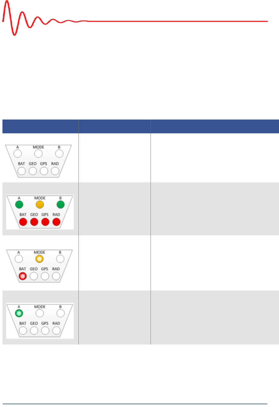
4Verify that the radio powers up. The LED indicators have the following
meanings:
5Click the Windows Start icon.
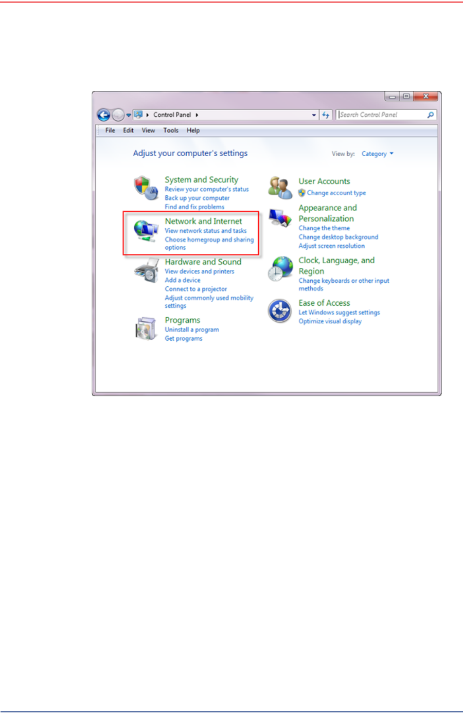
6Select Control Panel. The Control Panel window opens.
7Select Network and Internet.
Figure 3–16 Fluidmesh Radio Private Network
Table 3–5 Fluidmesh Radio LEDs
LED State Description
Power On / Green On whenever the radio has
power
LAN On / Green On whenever the radio has an
Ethernet connection
Signal Strength (1) On / Red BootingCoresystem
Signal Strength (2) On / Orange Bootingwirelesssystem
Signal Strength (3) On / Green Bootingroutingengine
Signal Strength (4) On / Green Bootingunitconfiguration
5Mbps Draft
48 RT 1000 1.5.0 Deployment Guide R03.h
© 2010-2012 Wireless Seismic, Inc. All rights reserved.
3. Backhaul
Configure the Radios
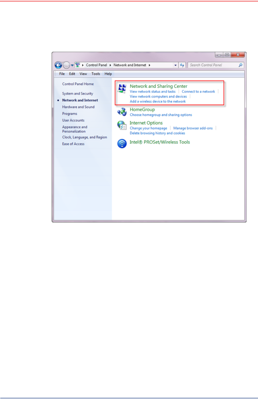
8Select Network and Sharing Center.
Figure 3–17 Control Panel, Network and Internet
5Mbps Draft
R03.h RT 1000 1.5.0 Deployment Guide 49
© 2010-2012 Wireless Seismic, Inc. All rights reserved.
3. Backhaul
Configure the Radios
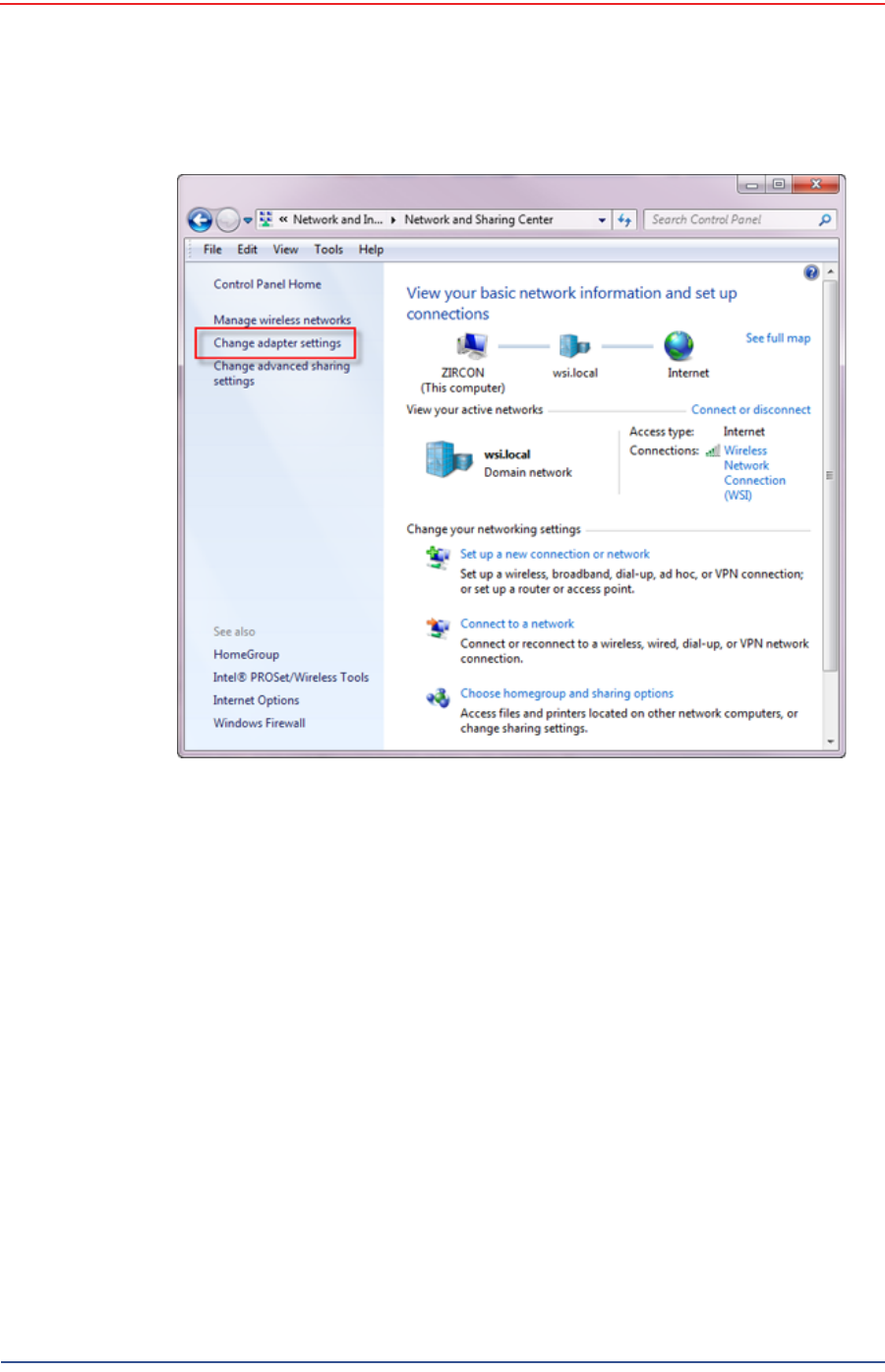
9In the left pane, select Change adapter settings.
Figure 3–18 Control Panel, Network and Sharing Center
5Mbps Draft
50 RT 1000 1.5.0 Deployment Guide R03.h
© 2010-2012 Wireless Seismic, Inc. All rights reserved.
3. Backhaul
Configure the Radios
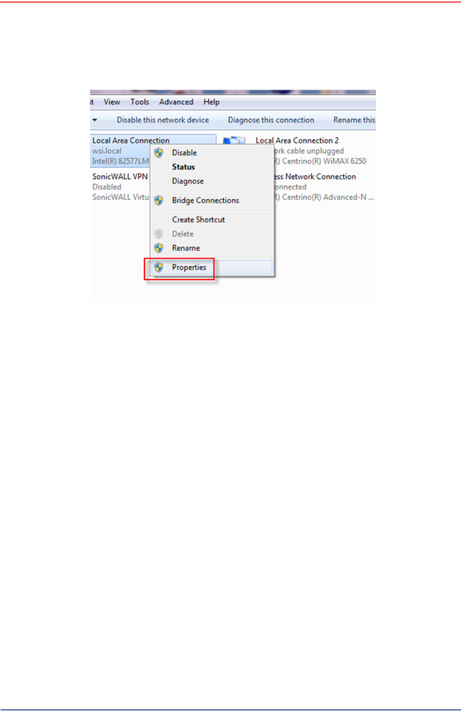
10 Right-click Local Area Connection and select Properties. The Properties
window opens.
Figure 3–19 Control Panel, Change Adapter Settings
5Mbps Draft
R03.h RT 1000 1.5.0 Deployment Guide 51
© 2010-2012 Wireless Seismic, Inc. All rights reserved.
3. Backhaul
Configure the Radios
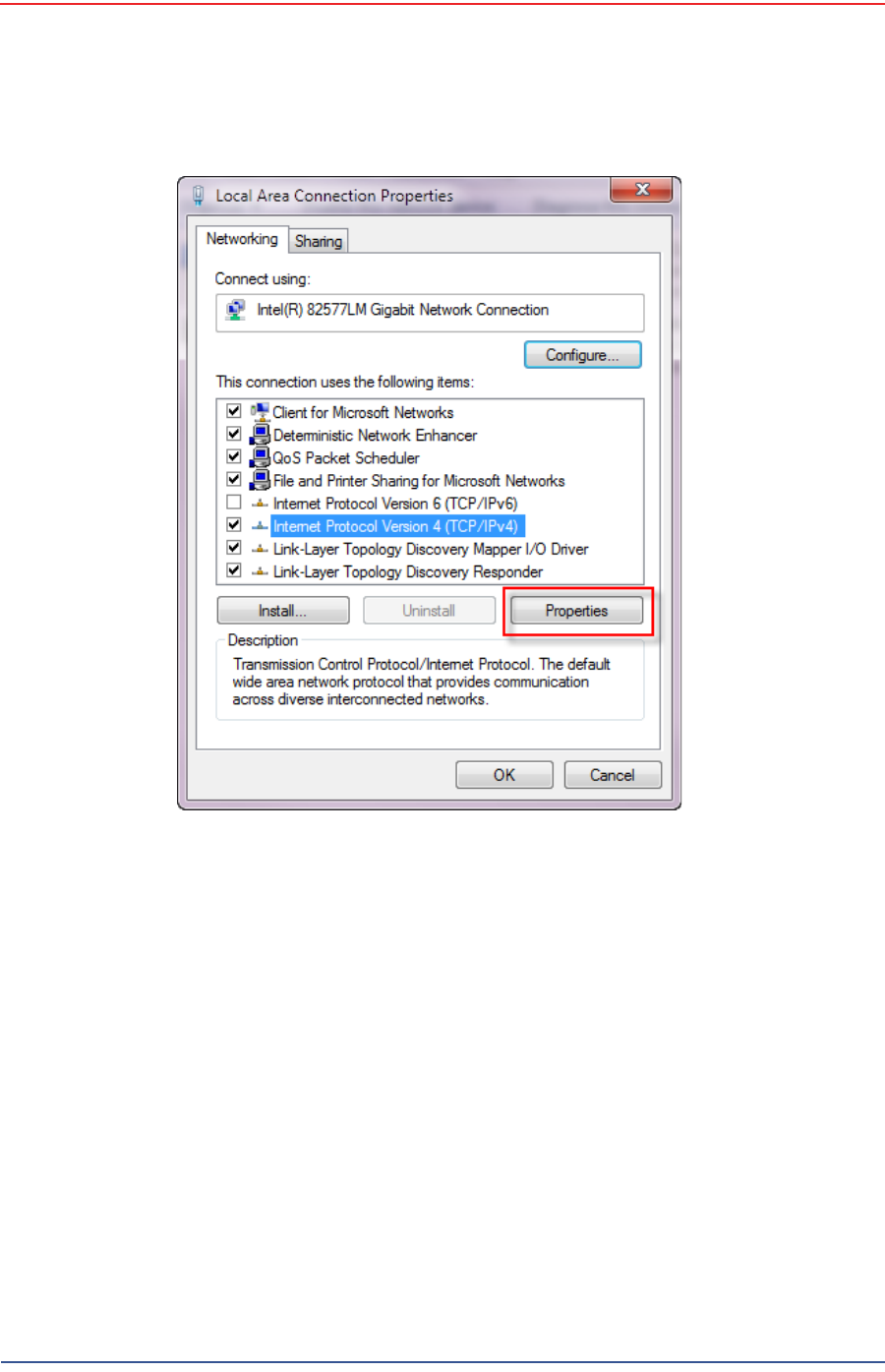
11 Select Internet Protocol Version 4 (TCP/IP v4) and click Properties.
Figure 3–20 Control Panel, LAN Properties
5Mbps Draft
52 RT 1000 1.5.0 Deployment Guide R03.h
© 2010-2012 Wireless Seismic, Inc. All rights reserved.
3. Backhaul
Configure the Radios
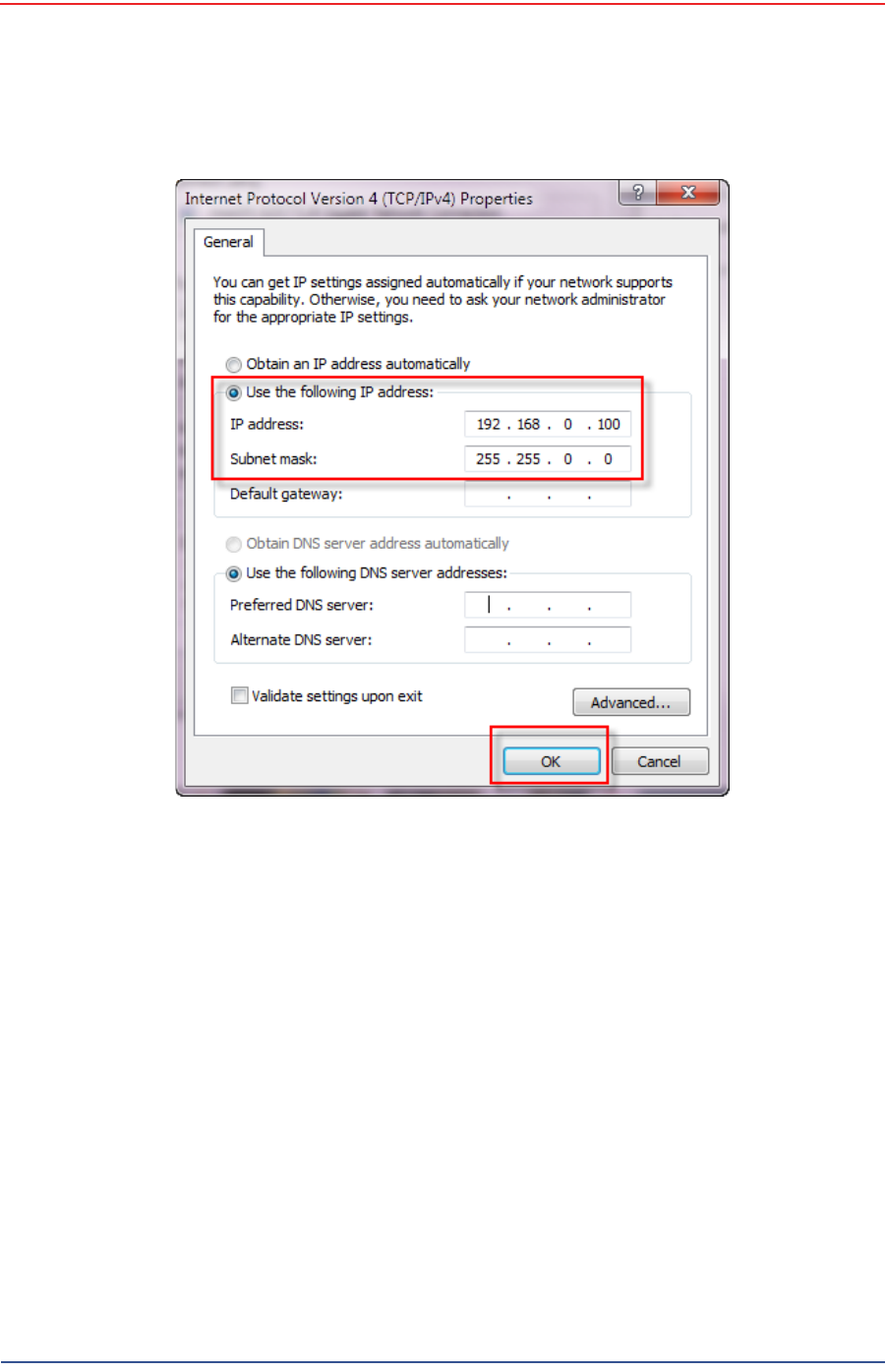
12 Select Use the following IP address.
Figure 3–21 Control Panel, Networking Properties
5Mbps Draft
R03.h RT 1000 1.5.0 Deployment Guide 53
© 2010-2012 Wireless Seismic, Inc. All rights reserved.
3. Backhaul
Configure the Radios
13 Enter the following:
●IP address: 192.168.0.100 (this number does not have to be 100, just
something other than 10, and a number between 1 and 255)
●Netmask:255.255.255.0
Figure 3–22 Control Panel, IP Address

5Mbps Draft
54 RT 1000 1.5.0 Deployment Guide R03.h
© 2010-2012 Wireless Seismic, Inc. All rights reserved.
3. Backhaul
Configure the Radios
14 Click OK.
15 Click Close.
3.3.2 Setting NIC Priority
If you have more than one network interface card (NIC) in your computer, make
sure that the LAN card has the highest priority; the computer attempts to use the
NICs in the order listed.
To set NIC priority:
→Windows computer
1Click the Windows Start icon.
2Select Control Panel. The Control Panel window opens.
3Select Network and Internet.
4Select Network and Sharing Center.
5In the left pane, select Change adapter settings.
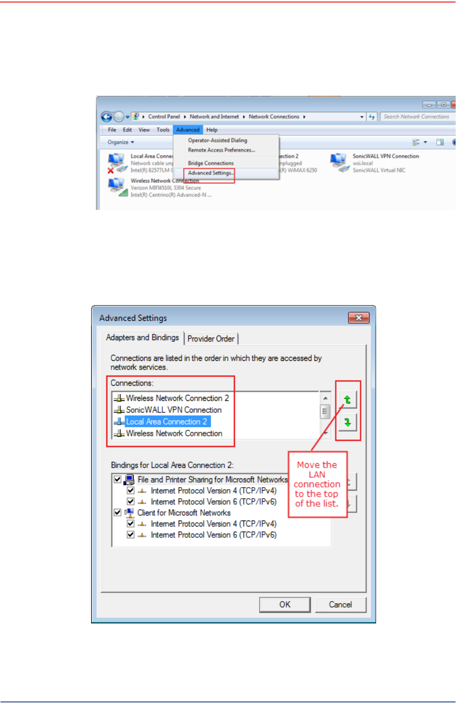
6In the toolbar, click Advanced, and then Advanced Settings.
NOTE
If the radio already has an IP address, you will need to enter different
numbers. For example:
Radio IP address: 10.101.0.22
Computer IP address: 10.168.0.100
Subnet Mask: 255.0.0.0
You may need to disable and enable (right-click) the LAN connection if
it displays Network cable unplugged in the Network Connections
window.
If the radio gets reset, the default IP address is 192.168.0.10.
5Mbps Draft
R03.h RT 1000 1.5.0 Deployment Guide 55
© 2010-2012 Wireless Seismic, Inc. All rights reserved.
3. Backhaul
Configure the Radios
7Select Local Area Connection and then click the up arrow repeatedly until
Local Area Connection is the first item.
Figure 3–23 Advanced Network Settings Menu
Figure 3–24 LAN Hierarchy
5Mbps Draft
56 RT 1000 1.5.0 Deployment Guide R03.h
© 2010-2012 Wireless Seismic, Inc. All rights reserved.
3. Backhaul
Configure the Radios
8Click OK.
3.3.3 Configure the Radio
Configure the radios by logging into the software located on the radio. FM1100s
are configured as mesh points, and FM3100s are configured as mesh ends.
To configure the radio:
→Windows computer
1On the computer, point a browser to the following URL:
http://192.168.0.10
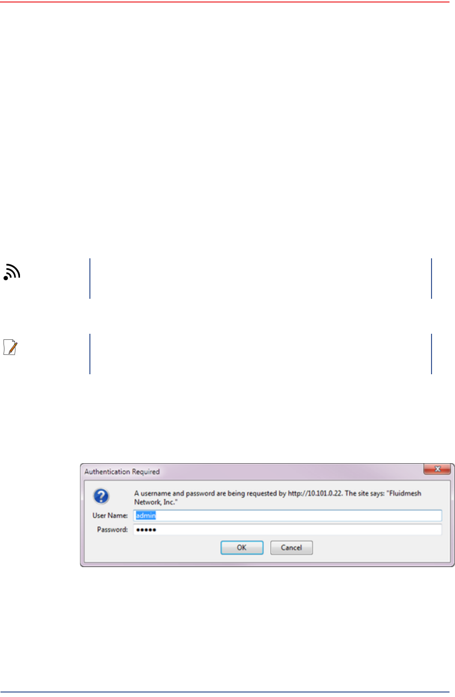
2Log in to the radio Web interface using the following:
●UserName: admin
●Password: admin
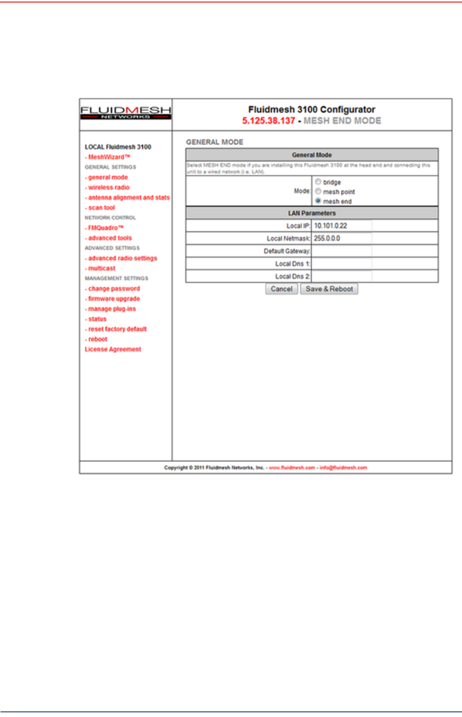
3The following figure shows the home window when mesh end is selected as
the Mode. The FM1100 configuration includes an additional left-pane option:
Power Over Ethernet. Click MeshWizard™.
TIP
Use Mozilla Firefox or Google Chrome. Internet Explorer does not
refresh correctly.
NOTE
If the radio has an IP address other than the default IP address, you will
need to enter that number. For example, 10.101.0.22.
Figure 3–25 Radio Login Window
5Mbps Draft
R03.h RT 1000 1.5.0 Deployment Guide 57
© 2010-2012 Wireless Seismic, Inc. All rights reserved.
3. Backhaul
Configure the Radios
4Click I Agree to accept the licence agreement if prompted.
5Click Wizard.
6Select or enter the following:
●Mode
►FM1100 – Mesh Point
►FM3100 – Mesh End
●IP Address – Use next class A address available (10.2.0.1 - 10.2.0.255)
●Netmask – 255.0.0.0
●Default Gateway
►FM1100 – Not shown or available
Figure 3–26 Radio Home Window, Mesh End
5Mbps Draft
58 RT 1000 1.5.0 Deployment Guide R03.h
© 2010-2012 Wireless Seismic, Inc. All rights reserved.
3. Backhaul
Configure the Radios
►FM3100 – Leave blank
7Click Next.
8Select one of the following frequencies (see Figure 3–9 Channel Color Example
on page 40):
●Channel 1 = 5745 MHz (Yellow label)
●Channel 2 = 5805 MHz (Blue label)
●Channel 3 = 5180 MHz (Red label)
●Channel 4 = 5785 MHz (Green label)
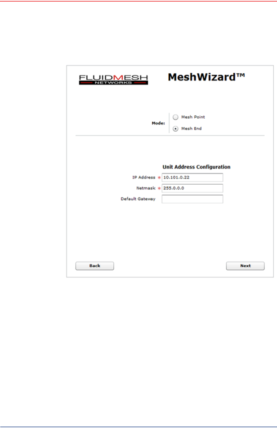
9Click Next.
10 Verify the settings. Click Save&Reboot.
Figure 3–27 Fluidmesh MeshWizard Interface

5Mbps Draft
R03.h RT 1000 1.5.0 Deployment Guide 59
© 2010-2012 Wireless Seismic, Inc. All rights reserved.
3. Backhaul
Setting up the Backhaul Equipment
11 FM1100 only:
●Click poe pass-through in the ADVANCED SETTINGS area of the left
pane. This option allows the LAN 2 port on the radio to deliver passive PoE
to a second FM1100 on the mast using one short Ethernet cable.
●Select Enable for the Status.
●Click Apply.
3.3.4 Restore your Network Settings
When have finished configuring all of your radios, restore your network settings as
described in this section.
To restore network settings:
→Windows computer
1Click the Windows Start icon.
2Select Control Panel. The Control Panel window opens.
3Select Network and Internet.
4Select Network and Sharing Center.
5In the left pane, select Change adapter settings.
6Right-click Local Area Connection and select Properties. The Properties
window opens.
7Select Internet Protocol Version 4 (TCP/IP v4) and click Properties.
8Select Obtain IP address automatically.
9Click OK.
10 Click Close.
3.3.5 Using the Fluidmesh Interface to Scan
TBD
3.3.6 Using the Fluidmesh Interface to Ping
TBD
3.4 Setting up the Backhaul Equipment
Use the following procedure to erect and secure the mast
5Mbps Draft
60 RT 1000 1.5.0 Deployment Guide R03.h
© 2010-2012 Wireless Seismic, Inc. All rights reserved.
3. Backhaul
Setting up the Backhaul Equipment
To install the backhaul components and erect the mast:
1Prerequisites:
●Gather the components
●Screwdriver
●Hammer
2Refer to the deployment instructions to determine the location and compass
heading to the next back haul site closer to central.
3Use the compass to determine and mark that direction.
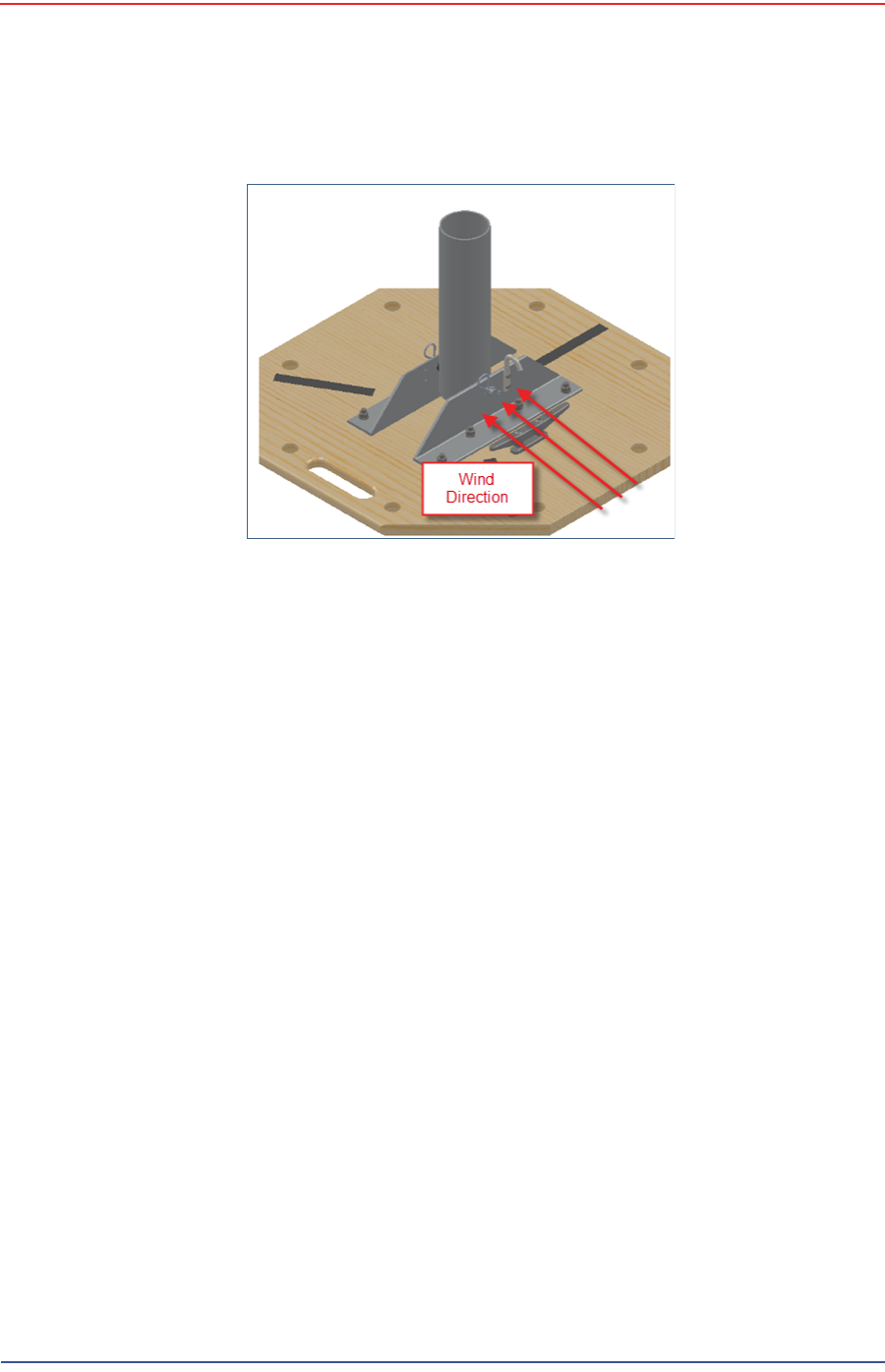
4Use the following considerations while positioning the base:
●Locate the base such that the three guy lines and the mast clear
obstructions during erection and while in operation.
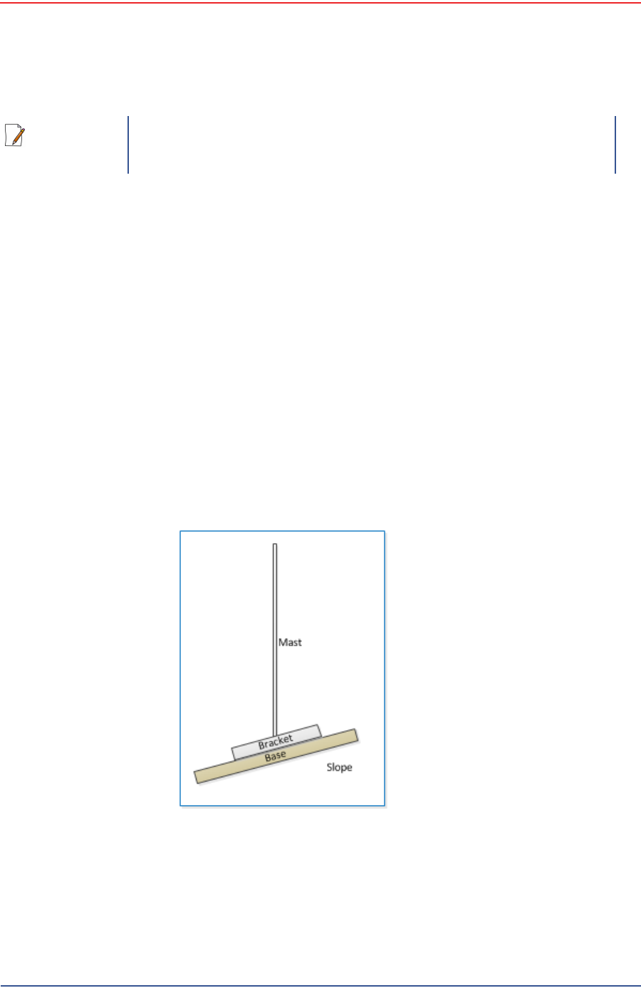
●If the ground is sloped, position the base such that when the base is flush
to the ground, the bracket orientation allows the mast to remain
perpendicular to the ground as shown in the following figure:
●If the wind is blowing, the mast is more stable when the brackets are
perpendicular to the wind as shown in the following figure:
NOTE
There are many possible mast options; the following instructions are a
general guideline.
Figure 3–28 Mast on a Slope
5Mbps Draft
R03.h RT 1000 1.5.0 Deployment Guide 61
© 2010-2012 Wireless Seismic, Inc. All rights reserved.
3. Backhaul
Setting up the Backhaul Equipment
5Collect all of the mast components.
6Secure the base with at least 2 nails or if using a weighted mast, with cement
blocks.
7Insert the mast into the base collar, extend and secure each section of the
mast.
8Attach the guy lines to the collar on the mast, or make loops in the lines and
slip them over the mast.
9Align one guy line so that it extends in the opposite direction from the mast
while the mast is still on the ground.
10 Align the other two guy lines at 120 degrees (1/3 of a circle) from the first guy
line.
11 Hammer guy line stakes into ground and secure guy lines at the indicated
marks.
12 Attach the radio or radios at the top of the mast.
13 Uncoil an Ethernet cable, attach one end to a radio unit and the other end to
the PoE. Form a service loop (extra cable) by looping the Ethernet cable over
the top of the radio unit. If you are installing two radios on the mast, refer to
“Installing Two Radios on the Mast” on page 63 for cabling and configuration
instructions.
14 Ensure that all directional antennas, when raised, are pointed correctly. The
radio unit should be facing toward the recording truck.
15 While holding the free guy line, lift / walk the mast to a vertical position and
secure the line into the cleat.
16 Adjust all lines to bring the mast to a vertical position.
17 Ensure that each line is firmly seated in each cleat, loosely wrap lines around
mast and secure at the large cleat on the base.
Figure 3–29 Base and Wind Orientation
5Mbps Draft
62 RT 1000 1.5.0 Deployment Guide R03.h
© 2010-2012 Wireless Seismic, Inc. All rights reserved.
3. Backhaul
Setting up the Backhaul Equipment
18 Check to make sure that the antennas are aimed properly.
Figure 3–30 Securing Lines to Large Cleat
Figure 3–31 Backhaul Antenna Erected
5Mbps Draft
R03.h RT 1000 1.5.0 Deployment Guide 63
© 2010-2012 Wireless Seismic, Inc. All rights reserved.
3. Backhaul
Installing Two Radios on the Mast
19 Uncoil an Ethernet cable. Attach one end to the BSU and the other end to the
PoE.
20 Check Ethernet status lights, if not green or flashing green remove Ethernet
cable from the PoE, count to five and re-insert.
21 If status does not change to green or flashing green report the condition.
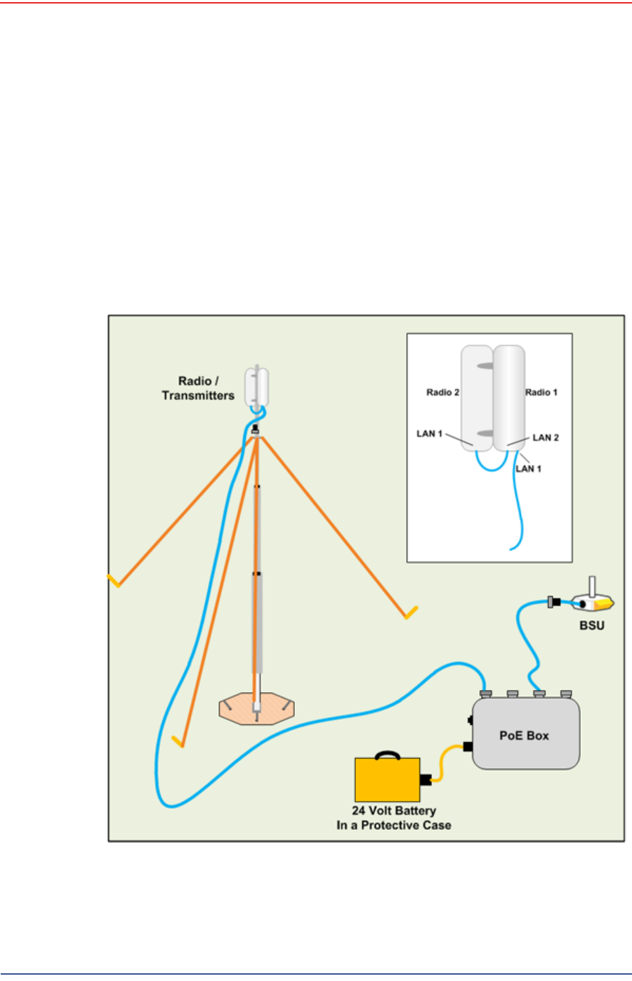
3.5 Installing Two Radios on the Mast
When you are installing a remote backhaul, there can be two radios on the mast
as shown in the following figure:
Figure 3–32 Two-Radio Installation

5Mbps Draft
64 RT 1000 1.5.0 Deployment Guide R03.h
© 2010-2012 Wireless Seismic, Inc. All rights reserved.
3. Backhaul
Removing the Backhaul Equipment
To install two radios on the mast:
1Prerequisites:
●TBD
●The radios are configured to allow the PoE option (see step 11 on page 59).
●The radios are BOTH configured as mesh POINTS (see step 6 on page 57).
2Attach two radios to the mast. Refer to the deployment instructions for the
location at which to aim the radio. One should point towards the recording
truck (uplink), and the other should point towards the next remote backhaul
location (downlink).
3Connect the two radios with a short Ethernet cable: Radio1/LAN 2 to Radio 2/
LAN 1.
4Connect Radio 1/LAN 1 to the PoE.
3.6 Removing the Backhaul Equipment
TBD
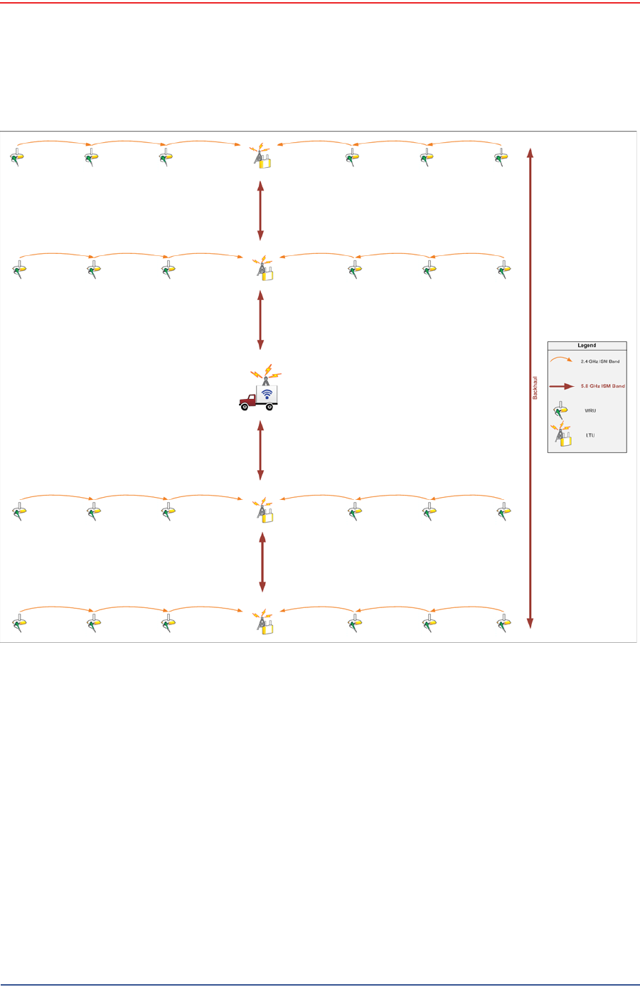
3.7 Use Cases or Example Deployments
This section shows a few example deployments.
5Mbps Draft
R03.h RT 1000 1.5.0 Deployment Guide 65
© 2010-2012 Wireless Seismic, Inc. All rights reserved.
3. Backhaul
Use Cases or Example Deployments
Figure 3–33 2D Single Backhaul
5Mbps Draft
66 RT 1000 1.5.0 Deployment Guide R03.h
© 2010-2012 Wireless Seismic, Inc. All rights reserved.
3. Backhaul
Use Cases or Example Deployments
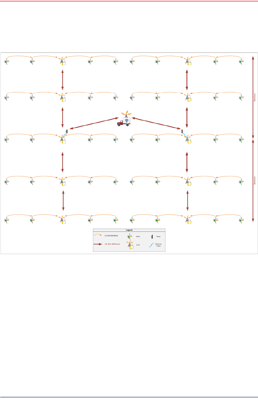
Figure 3–34 3D Dual Backhaul, Two Root Nodes
5Mbps Draft
R03.h RT 1000 1.5.0 Deployment Guide 67
© 2010-2012 Wireless Seismic, Inc. All rights reserved.
3. Backhaul
Use Cases or Example Deployments
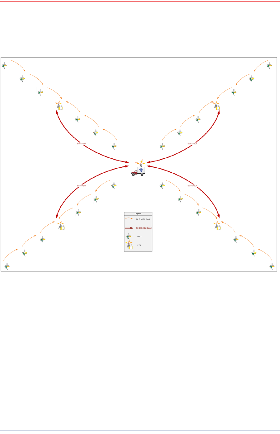
Figure 3–35 2D Single Backhaul, Star Configuration

5Mbps Draft
RT 1000 1.5.0 68 Deployment Guide R03.h
© 2010-2012 Wireless Seismic, Inc. All rights reserved.
4
4. Demobilization
4.1 Overview
This chapter describes how to prepare (undeploy) the ground electronics for
transport at the end of a project (demobilization).
4.2 Removing the WRU from the Field
This section describes the process to ready the WRU for movement to a new
physical location or to remove it in preparation for demobilization.
To undeploy the WRU:
1Prerequisites:
●The WRU is assembled with battery, geophone, and antenna
●The WRU is in an active, transitional, or ready state
2Pick up the WRU and point the geophone connector end towards the sky as
shown in the following figure. All of the LEDs illuminate:
Figure 4–1 Power Off the
Unit

5Mbps Draft
R03.h RT 1000 1.5.0 Deployment Guide 69
© 2010-2012 Wireless Seismic, Inc. All rights reserved.
4. Demobilization
Disassemble the WRU
3Place the unit flat in the transportation vehicle as shown in the following figure.
The unit shuts down. The LEDs on the top of the unit are off.
4Optional: Remove batteries, antenna, or geophone as described in
“Disassemble the WRU” on page 69.
4.3 Disassemble the WRU
This section describes the process to disassemble the WRU prior to demobilization.
To disassemble the WRU:
1Undeploy the equipment as described in “Removing the WRU from the Field” on
page 68.
2Remove the antenna from the unit.
Figure 4–2 Undeployed Unit
5Mbps Draft
70 RT 1000 1.5.0 Deployment Guide R03.h
© 2010-2012 Wireless Seismic, Inc. All rights reserved.
4. Demobilization
Disassemble the WRU
3Remove the geophone from the unit.
4Remove the batteries from the unit.
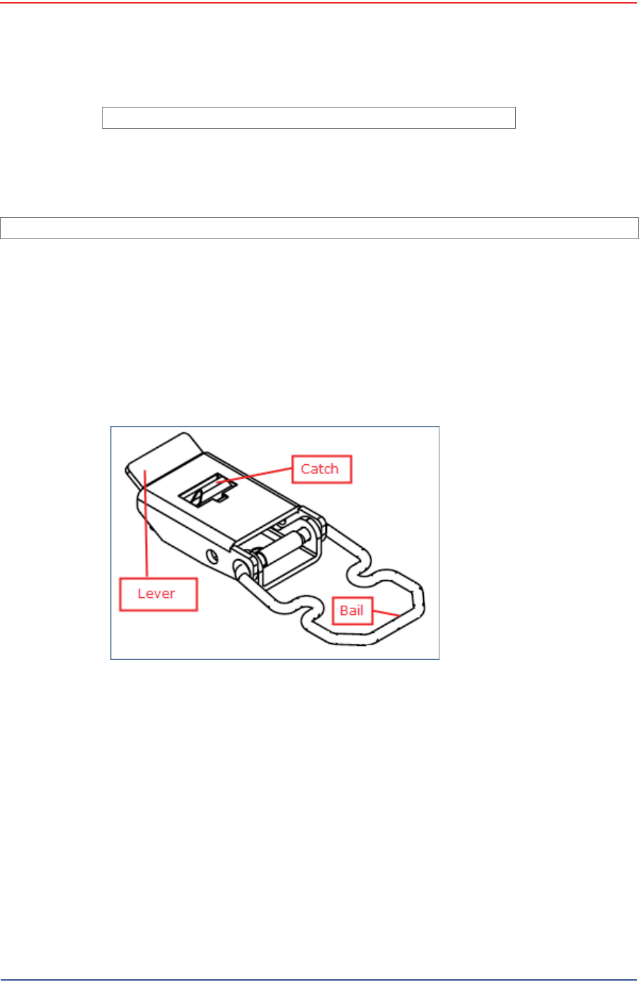
●Press the catch on the battery latch.
●Lift the lever, but do not lift the bail from the molded area on the battery.
●Continue to lift the lever using the bail to push the battery out of the
connector.
5Secure the equipment in the transport vehicle.
TBD
Figure 4–3 Removing the Antenna
Image showing geophone installation TBD.
Figure 4–4 Removing the Geophone
Figure 4–5 Removing the Battery

5Mbps Draft
RT 1000 1.5.0 71 Deployment Guide R03.h
© 2010-2012 Wireless Seismic, Inc. All rights reserved.
5
5. Maintaining the Equipment
5.1 Units
TBD
5.2 Antennas
Ensure that the antennas are snug.
TBD
5.3 Geophones
Ensure that the geophone connection is clean and snug.
TBD
WARNING
In order to comply with FCC radio frequency (RF) exposure
requirements, the RT 1000 units must be installed so that a minimum
separation distance of 20 cm is maintained between the antenna(s) and
all persons at all times during normal operation.
WARNING
AVERTISSEM
ENT
Afin de se conformer aux exigences de la FCC en matière d'exposition
aux radiofréquences (RF), les unités RT 1000 doivent être installées de
manière à garder en permanence une distance minimale de 20 cm entre
la ou les antennes et toute personne en mode de fonctionnement
normal.

5Mbps Draft
72 RT 1000 1.5.0 Deployment Guide R03.h
© 2010-2012 Wireless Seismic, Inc. All rights reserved.
5. Maintaining the Equipment
Cautions
5.4 Cautions
TBD

5Mbps Draft
RT 1000 1.5.0 73 Deployment Guide R03.h
© 2010-2012 Wireless Seismic, Inc. All rights reserved.
6
6. Troubleshooting and Tips
6.1 Best Practices
This section provides some tips on working with the equipment.
6.1.1 24 Ah Batteries
In order to maintain the best possible communication channel, observe the
following tips:
Place a fully charged 24 Ah battery on the backhaul every day.(90-0012)
Keep extra 24 Ah batteries charged up at the staging area.
Store 24 Ah batteries at the staging area when not in use. Deep
discharging of the batteries can shorten their lifespan considerably.
6.1.2 PoE
When temperature swings are extreme, or weather is severe, store the PoE
boxes in the recording truck at night.
To ensure a protected connection, be sure to use an Ethernet cable with a
protective shell (65-0051) when connecting Ethernet cables to the PoE (see
Figure 3–8 Protective Ethernet Connector on page 38).
6.1.3 Urban Environments
The following could impact your configuration in urban environments:
You may need to use repeaters when crossing a road.
You may need to extend the antenna with coaxial cable
You may need to adjust WRU placement and antenna strength when
crossing a road.
You will need to consider the presence of power lines and buildings when
placing WRUs and backhaul components.
CAUTION
Do not allow the PoE battery to remain connected at a voltage of 22V or
less. Damage to the equipment could occur.

5Mbps Draft
74 RT 1000 1.5.0 Deployment Guide R03.h
© 2010-2012 Wireless Seismic, Inc. All rights reserved.
6. Troubleshooting and Tips
Troubleshooting
6.1.4 Ethernet Cables
Use CAT6 enhanced quality cables.
To ensure a protected connection, be sure to use an Ethernet cable with a
protective shell (65-0051) when connecting Ethernet cables to the PoE (see Figure
3–8 Protective Ethernet Connector on page 38).
6.1.5 Antennas
When placing or selecting antennas in, consider the following:
In areas where there is a steep inclination, smaller gain antennas may provide
a better signal.
In areas where there is a steep inclination, try to reduce the inclination by
going up or down at an angle rather than straight up or down.
Use repeaters to cover overpass and steep inclination situations.
If you need more signal strength, use an extender with a riser to elevate the
antenna. This is the typical scenario with the BSU at the backhaul location.
6.2 Troubleshooting
TBD
6.2.1 Fluidmesh Radios
TBD
Table 6–1 Troubleshooting Fluidmesh Radios
Problem Solutions
Not communicating • Try sending a ping command in a CMD window to the IP address of the
radio.
• If you are trying to connect directly with a computer, make sure you
have configured a private network (see “Create a Private Network” on
page 46).
• Ensure that you have configured the radios as follows:
- FM1100 = mesh POINT (remote backhaul)
- FM3100 = mesh END (central backhaul)
Cannot access GUI If you configure two FM1100 radios on the same mast to be a mesh POINT
and a mesh END, they will communicate over the switch and lock
everything else out of the communication loop. They must both be
configured as mesh POINTs
GUI not responding It takes one full minute to see the alignment statistics in the Fluidmesh GUI
(from the browser), so be sure to wait for it.

5Mbps Draft
RT 1000 1.5.0 75 Deployment Guide R03.h
© 2010-2012 Wireless Seismic, Inc. All rights reserved.
7
7. Batteries
This chapter provides information about the batteries and battery
requirements used in the Wireless Seismic, Inc. RT 1000 system.
7.1 Lithium Ion Batteries
This section provides information regarding the characteristics, use, and
handling of lithium ion batteries. See the following sections for details:
●“Specifications” on page 75
●“Handling and Safety Guidelines” on page 76
●“Transportation” on page 77
●“Storage” on page 78
7.1.1 Specifications
The RT 1000 uses one or two custom intelligent lithium-ion batteries with self-
contained charging circuitry that protects the batteries from overcharge,
discharge, short circuits, or extreme temperature charging.
Battery specifications are shown in the following table:RT 1000RT 1000
Table 7–1 Lithium Ion Battery Specifications
Item Description Value
Voltage Nominal 3.7 VDC
Shut-off 2.8 VDC
Full (90%) charge 4.1 VDC
Full (90%) charge
mAh Approximately 12,000
mAh at nominal voltage
Full (90%) charge
mWh Approximately 44,400
mWh at nominal voltage
Connector 5-pin

5Mbps Draft
76 RT 1000 1.5.0 Deployment Guide R03.h
© 2010-2012 Wireless Seismic, Inc. All rights reserved.
7. Batteries
Lithium Ion Batteries
7.1.2 Handling and Safety Guidelines
Observe the following handling and safety guidelines:
If a battery pack has leaking fluids, do not touch any fluids. Dispose of a
leaking battery pack. In case of eye contact with fluid, do not rub eyes.
Immediately flush eyes thoroughly with water for at least 15 minutes, lifting
upper and lower lids until no evidence of the fluid remains. Seek medical
attention.
Do not disassemble, crush, or puncture a battery
Do not short the external contacts on a battery
Do not dispose of a battery in fire or water
Do not expose a battery to temperatures above 60 °C (140 °F)
Keep the battery away from children
Avoid exposing the battery to excessive shock or vibration
Do not use a damaged battery
Lithium Ion battery packs MUST be completely discharged before disposal
Although there may be local or state restrictions, lithium ion batteries are
considered by the Federal Government as “non-hazardous universal waste”.
There are restrictions for large quantity handlers of universal waste that define
labeling, containment, and so on. Whenever possible the batteries must be
LED One LED that indicates
charging status when
connected to the charging
station as follows
• Green – Charged
•Red – Charging
• Amber – Transitional
phase between
charging and charged,
or charge temperature
limits exceeded
Label One bar code serial
number label
Temperature Operating From -50°C to +75°C
Charging From 0°Cto+45°C
Ambient Storage • From -20°C to +45°C
for a maximum period
of one month
• From -20°C to +35°C
for a maximum of 6
months, after which
time the battery packs
will need to be
recharged to above
50% capacity
Table 7–1 Lithium Ion Battery Specifications (cont.)
Item Description Value

5Mbps Draft
R03.h RT 1000 1.5.0 Deployment Guide 77
© 2010-2012 Wireless Seismic, Inc. All rights reserved.
7. Batteries
Lithium Ion Batteries
discharged before disposal. Battery leads/contacts should be taped off to
prevent accidental shorting. Each battery pack should be placed in a plastic
bag.
Recycling is encouraged when practical and applicable. The batteries contain
recyclable material and are accepted by several battery recycling companies.
Refer to one of the following for more information on recycling and disposal:
●http://www.swe.com
●http://www.rbrc.org
●http://www.call2recycle.org
●1-800-8-BATTERY
●1-877-2-RECYCLE
7.1.3 Transportation
In the United States, large lithium ion battery shipments (more than 24 cells or 12
batteries per package) are regulated as hazardous material (Class 9) by the
Federal Government and are subject to the regulations described in the following:
Code of Federal Regulations, Title 49 Transportation.
http://ecfr.gpoaccess.gov/cgi/t/text/text-
idx?sid=92868a82add6feba6afa796572133179&c=ecfr&tpl=/ecfrbrowse/
Title49/49tab_02.tpl
International Air Transport Association (IATA)
http://www.iata.org/whatwedo/cargo/dangerous_goods/pages/
lithium_batteries.aspx
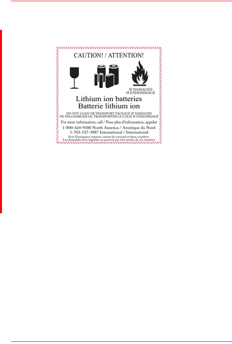
Batteries can be ground shipped only if all of the following conditions are met:
Box used meets the 1.2 m drop test box (“UN” rated box) for packaging
Battery pack terminals are protected to prevent a short circuit
Gross weight does not exceed 30 kg (66 pounds)
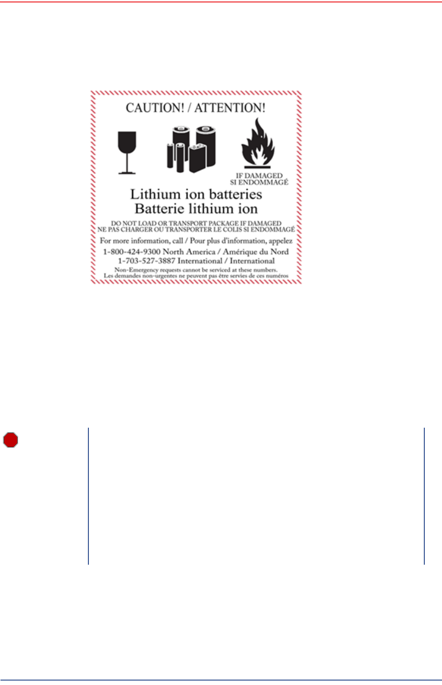
Outer package is labeled with the current required label. An example is shown
in the following figure.
5Mbps Draft
78 RT 1000 1.5.0 Deployment Guide R03.h
© 2010-2012 Wireless Seismic, Inc. All rights reserved.
7. Batteries
Lithium Ion Batteries
Batteries can be air shipped only if all of the following conditions are met:
Box used meets the 1.2 m drop test box (“UN” rated box) for packaging
Maximum weight of each package does not exceed 10 kg (22 lbs)
Battery pack terminals are protected to prevent a short circuit
Outer package is labeled with the current required label. An example is shown
in the previous figure (“Example Battery Shipping Label” on page 78).
7.1.4 Storage
Proper storage and maintenance of Lithium Ion batteries is essential to maximize
their useful life and avoid catastrophic failure. Observe the following storage
precautions:
Figure 7–1 Example Battery Shipping Label
WARNING
The information contained in this document is intended to provide
general awareness of battery regulations; it is not comprehensive, and
the requirements referenced herein may have changed. Nothing in this
chapter or the Deployment Guide constitutes legal advice or is intended
to address any specific legal, compliance, or regulatory issues that may
arise in particular circumstances. This chapter and the Deployment
Guide are not intended to replace current, official regulations regarding
the packaging and shipment of hazardous materials or independent
legal counsel on these issues. You are solely responsible for compliance
with all applicable laws, regulations, and other requirements. Please
refer to an official copy of the current version of these documents for
the latest information.

5Mbps Draft
R03.h RT 1000 1.5.0 Deployment Guide 79
© 2010-2012 Wireless Seismic, Inc. All rights reserved.
7. Batteries
Charging Lithium Ion Batteries
Remove the batteries from the WRU for storage
The recommended storage temperature for Lithium ion batteries is as follows:
●From -20°C to +45°C for a maximum period of one month
●From -20°C to +35°C for a maximum of 6 months, after which time the
battery packs will need to be recharged to above 50% capacity
●Storing at cooler temperatures slows down self discharge and capacity loss
over time. Store the batteries at 25°C or less if possible
The recommended storage charge levels are as follows:
●Charge (or discharge) batteries to a 30% to 50% charge level before
placing into storage. Higher or lower charge levels can reduce the battery
life.
●Never store the battery completely depleted of charge unless for disposal.
●Periodic charging is necessary to maintain 30% to 50% charge when stored
for a long period of time
Store batteries in a well ventilated area
Do not leave batteries unused for extended periods of time, either in the
product or in storage. When a battery has been unused for 6 months, check
the charge status and charge or dispose of the battery as appropriate.
Routinely check the battery’s charge status
Consider replacing the battery with a new one if you note either of the
following conditions:
●The battery run time drops below about 80% of the original run time
●The battery charge time increases significantly
7.2 Charging Lithium Ion Batteries
This section describes charging precautions and provides an overview of the
battery charger.
7.2.1 Charging Precautions
Observe the following charging precautions:
Prior to charging, inspect the battery for any visible damage to the case or
connector that could create an electrical shortage.
The temperature range over which the battery can be charged is 0°Cto+45°C.
Charging the battery outside of this temperature can cause the battery to
become hot or to break.
Be absolutely sure that only a 5 V source is used when charging the battery.
Care should be taken to charge batteries on a fireproof surface.
Do not charge batteries near flammable items or liquids.
Keep a Class C Dry Chemical fire extinguisher nearby.
5Mbps Draft
80 RT 1000 1.5.0 Deployment Guide R03.h
© 2010-2012 Wireless Seismic, Inc. All rights reserved.
7. Batteries
Charging Lithium Ion Batteries
Do not continue recharging the battery if it does not recharge within the
specified charging time.
A lithium ion battery should NEVER be left unattended while charging.
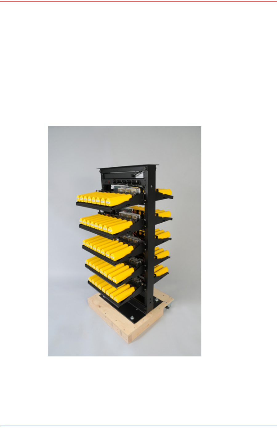
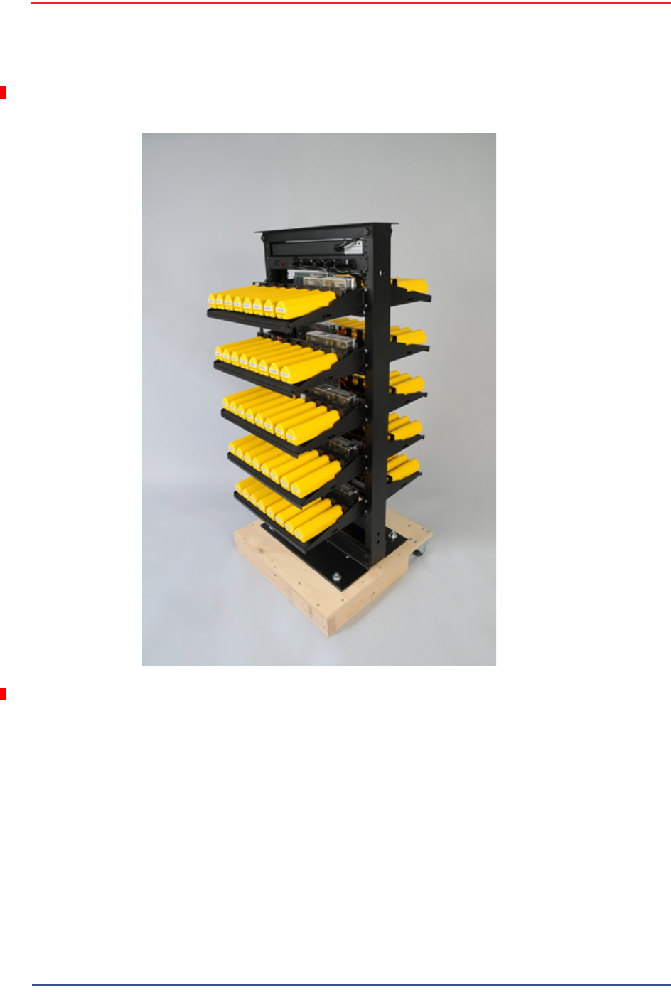
7.2.2 Battery Charger
The lithium ion battery charger is designed to operate from a single 10 A, 120 VAC
service line.
The power supply to charge the battery pack is a 5VDC regulated voltage supply.
Figure 7–2 Battery Charger

5Mbps Draft
R03.h RT 1000 1.5.0 Deployment Guide 81
© 2010-2012 Wireless Seismic, Inc. All rights reserved.
7. Batteries
BSU Battery
7.3 BSU Battery
TBD
Figure 7–3 Serial Number
Label and LED Indicator

5Mbps Draft
RT 1000 1.5.0 82 Deployment Guide R03.h
© 2010-2012 Wireless Seismic, Inc. All rights reserved.
8
8. Batteries
Ce chapitre fournit des informations sur les batteries utilisées dans le système
RT 1000 de Wireless Seismic, Inc.
8.1 Batteries au lithium-ion
Cette section fournit des informations sur les caractéristiques, l'utilisation et la
manipulation des batteries au lithium-ion. Reportez-vous aux sections
suivantes pour en savoir plus:
●“Spécifications” on page 82
●“Directives en matière de manipulation et de sécurité” on page 83
●“Transport” on page 84
●“Entreposage” on page 86
8.1.1 Spécifications
Le RT 1000 utilise une ou deux batteries au lithium-ion intelligentes et
personnalisées, dotées d'un circuit de charge autonome qui protège les
batteries contre les surcharges, décharges, courts-circuits ou changements
extrêmes de température.
Le tableau suivant indique les spécifications des batteries:
Tableau 8–1 Spécifications des batteries au lithium-ion
Élément Description Valeur
Tension Nominale 3,7 V c.c.
Arrêt 2,8 V c.c.
Charge complète (90 %) 4,1 V c.c.
Charge complète (90
%) mAh Environ 12 000 mAh à la
tension nominale
Charge complète (90
%) mWh Environ 44 400 mWh à la
tension nominale
Connecteur 5 broches

5Mbps Draft
R03.h RT 1000 1.5.0 Deployment Guide 83
© 2010-2012 Wireless Seismic, Inc. All rights reserved.
8. Batteries
Batteries au lithium-ion
8.1.2 Directives en matière de manipulation et de
sécurité
Respecter les directives suivantes en matière de manipulation et de sécurité :
Si un bloc-batterie présente une fuite de liquides, ne pas toucher les liquides.
Jeter le bloc-batterie en cas de fuite. En cas de contact oculaire avec du liquide,
ne pas se frotter les yeux. Rincer immédiatement les yeux avec de l'eau
pendant au moins 15 minutes, en soulevant les paupières supérieures et
inférieures jusqu'à ce qu'il n'y ait plus de trace de liquide. Consulter un
médecin.
Ne pas démonter, écraser ou percer une batterie
Ne pas court-circuiter les contacts externes d'une batterie
Ne pas jeter une batterie dans le feu ou l'eau
Ne pas exposer une batterie à des températures supérieures à 60 °C (140 °F)
Maintenir la batterie à l'écart des enfants
Éviter d'exposer la batterie à des vibrations ou chocs excessifs
Ne pas utiliser une batterie endommagée
DEL Une DEL qui indique l'état
de charge lors de la
connexion à la station de
charge, de la manière
suivante :
•Vert : chargé
• Rouge : en train de
charger
• Orange : phase
transitionnelle entre
l'état de chargement
et l'état chargé, ou
dépassement des
limites de la
température de
charge
Étiquette Une étiquette indiquant le
numéro de série sous
forme de code à barres
Température Fonctionnement De -50°C à +75°C
Chargement De 0°Cà+45°C
Entreposage à
température ambiente • De -20°C à +45°C
durant une période
maximum d'un mois
• De -20°C à +35°C
durant 6 mois
maximum ; passé ce
délai, les blocs-
batteries doivent être
rechargés à plus de
50 % de leur capacité
Tableau 8–1 Spécifications des batteries au lithium-ion (cont.)
Élément Description Valeur

5Mbps Draft
84 RT 1000 1.5.0 Deployment Guide R03.h
© 2010-2012 Wireless Seismic, Inc. All rights reserved.
8. Batteries
Batteries au lithium-ion
Les blocs-batteries au lithium-ion DOIVENT être entièrement déchargés avant
leur élimination
Bien qu'il puisse exister des restrictions locales ou nationales, les batteries au
lithium-ion sont considérées comme des « déchets universels non dangereux »
par le gouvernement fédéral. Il existe des restrictions qui s'appliquent à ceux
qui gèrent de grandes quantités de déchets universels ; celles-ci définissent
l'étiquetage, le confinement, etc. Dans la mesure du possible, les batteries
doivent être déchargées avant de les jeter. Les conducteurs/contacts de
batterie doivent être fixés de manière à éviter un court-circuit accidentel.
Chaque bloc-batterie doit être placé dans un sac en plastique.
Le recyclage est encouragé lorsqu'il est réalisable. Les batteries contiennent
des matériaux recyclables et sont acceptées par plusieurs entreprises de
recyclage de batteries. Reportez-vous à l'un des éléments suivants pour obtenir
plus d'informations sur le recyclage et l'élimination :
●http://www.swe.com
●http://www.rbrc.org
●http://www.call2recycle.org
●1-800-8-BATTERY
●1-877-2-RECYCLE
8.1.3 Transport
Aux États-Unis, les expéditions de grandes quantités de batterie au lithium-ion
(plus de 24 piles ou 12 batteries par colis) sont réglementées comme des matières
dangereuses (classe 9) par le gouvernement fédéral et sont soumises aux
règlements décrits ci-après :
Code of Federal Regulations, Title 49 Transportation.
http://ecfr.gpoaccess.gov/cgi/t/text/text-
idx?sid=92868a82add6feba6afa796572133179&c=ecfr&tpl=/ecfrbrowse/
Title49/49tab_02.tpl
International Air Transport Association (IATA)
http://www.iata.org/whatwedo/cargo/dangerous_goods/pages/
lithium_batteries.aspx
Les batteries ne peuvent être expédiées par voie terrestre que si toutes les
conditions suivantes sont satisfaites :
La boîte utilisée satisfait le test de chute de 1,2 m (boîte classée « UN ») de
boîte d'emballage
Les bornes de bloc-batterie sont protégées pour éviter un court-circuit
Le poids brut ne dépasse pas 30 kg (66 livres)
L'emballage extérieur porte l'étiquette requise en vigueur. La figure suivante en
montre un exemple.
5Mbps Draft
R03.h RT 1000 1.5.0 Deployment Guide 85
© 2010-2012 Wireless Seismic, Inc. All rights reserved.
8. Batteries
Batteries au lithium-ion
Les batteries ne peuvent être expédiées par voie aérienne que si toutes les
conditions suivantes sont satisfaites :
La boîte utilisée satisfait le test de chute de 1,2 m (boîte classée « UN ») de
boîte d'emballage
Les bornes de bloc-batterie sont protégées pour éviter un court-circuit
Le poids brut de chaque colis ne dépasse pas 10 kg (22 livres)
L'emballage extérieur porte l'étiquette requise en vigueur. La figure précédente
en montre un exemple (“Example Battery Shipping Label” on page 85).
Exemple 8–1 Example Battery Shipping Label

5Mbps Draft
86 RT 1000 1.5.0 Deployment Guide R03.h
© 2010-2012 Wireless Seismic, Inc. All rights reserved.
8. Batteries
Batteries au lithium-ion
8.1.4 Entreposage
Un entreposage et un entretien adéquats des batteries au lithium-ion est
indispensable pour optimiser leur durée de vie utile et éviter une défaillance
catastrophique. Respecter les précautions suivantes en matière d'entreposage :
Retirer les batteries de l'unité distante sans fil avant l'entreposage
Température d'entreposage recommandée des batteries au lithium-ion :
●De -20°C à +45°C durant une période maximum d'un mois
●De -20°C à +35°C durant 6 mois maximum ; passé ce délai, les blocs-
batteries doivent être rechargés à plus de 50 % de leur capacité
●L'entreposage à basses températures ralentit la décharge naturelle et la
perte de capacité au fil du temps. Entreposer les batteries à 25°C ou moins
si possible
Niveaux de charge d'entreposage recommandés :
●Charger (ou décharger) les batteries à un niveau de charge de 30 % à
50 % avant de les entreposer. Des niveaux de charge inférieurs ou
supérieurs peuvent réduire la durée de vie des batteries.
●Ne jamais entreposer des batteries entièrement déchargées, sauf en cas
d'élimination.
●Un chargement périodique est nécessaire pour maintenir une charge de
30 % à 50 % en cas d'entreposage de longue durée
Entreposer les batteries dans un endroit bien aéré
Ne pas laisser les batteries inutilisées pendant de longues durées, qu'elles
soient dans le produit ou placées en entreposage. Si une batterie n'a pas été
utilisée pendant 6 mois, vérifier l'état de charge et charger ou éliminer la
batterie, le cas échéant.
AVERTISSEMENT
Les informations contenues dans le présent document
ont pour but de fournir une connaissance générale des
règlements s'appliquant aux batteries. Elles ne sont pas
exhaustives, et les conditions mentionnées dans ce
document peuvent avoir changées. Rien dans le présent
chapitre ou dans le Guide de déploiement ne constitue
un avis juridique ou est destiné à répondre aux
problèmes juridiques, de conformité, ou réglementaires
spécifiques qui peuvent survenir dans des circonstances
particulières. Le présent chapitre et le Guide de
déploiement ne sont pas destinés à remplacer les
règlements officiels en vigueur concernant l'emballage
et l'expédition de matières dangereuses ou un conseil
juridique indépendant sur c es questions. Vous êtes
seul responsable du respect de toutes les lois,
règlements et autres exigences. Veuillez vous reporter à
une copie officielle de la version en vigueur de ces
documents pour obtenir les dernières informations.

5Mbps Draft
R03.h RT 1000 1.5.0 Deployment Guide 87
© 2010-2012 Wireless Seismic, Inc. All rights reserved.
8. Batteries
Chargement des batteries au lithium-ion
Vérifier régulièrement l'état de charge de la batterie
Envisager le remplacement de la batterie par une nouvelle en cas de constat
d'une des conditions suivantes :
●L'autonomie de la batterie descend en dessous d'environ 80 % de son
autonomie initiale
●Le temps de charge de la batterie augmente sensiblement
8.2 Chargement des batteries au lithium-ion
This section describes charging precautions and provides an overview of the
battery charger.
8.2.1 Précautions de chargement
Respecter les précautions de chargement suivantes :
Avant de la charger, inspecter la batterie pour détecter les signes éventuels de
dommages sur le boîtier ou les connecteurs susceptibles de créer un court-
circuit.
La batterie peut être chargée dans la plage de température de 0°Cà+45°C. En
cas de chargement de la batterie en dehors de cette plage, la batterie peut
devenir très chaude ou se rompre.
Être absolument sûr de l'utilisation d'une source de 5 V lors du chargement de
la batterie.
Prendre soin de charger les batteries sur une surface ininflammable.
Ne pas charger les batteries à proximité d'objets ou de liquides inflammables.
Conserver un extincteur à poudre chimique de classe C à proximité.
Ne pas continuer de recharger la batterie si elle ne se recharge pas dans le
temps de chargement spécifié.
NE JAMAIS laisser une batterie au lithium-ion sans surveillance lorsqu'elle est
en train de charger.
8.2.2 Chargeur de batterie
Le chargeur de batterie au lithium-ion est conçu pour fonctionner à partir d'une
ligne de service simple 120 V c.a., 10 A.
Le bloc d'alimentation servant à charger le bloc-batterie fournit une tension
régulée de 5 V c.c.
5Mbps Draft
88 RT 1000 1.5.0 Deployment Guide R03.h
© 2010-2012 Wireless Seismic, Inc. All rights reserved.
8. Batteries
Chargement des batteries au lithium-ion
Exemple 8–2 Chargeur de batterie

5Mbps Draft
R03.h RT 1000 1.5.0 Deployment Guide 89
© 2010-2012 Wireless Seismic, Inc. All rights reserved.
8. Batteries
BSU de batterie
8.3 BSU de batterie
TBD
Exemple 8–3 Étiquette avec
numéro de série et voyant
DEL

5Mbps Draft
RT 1000 1.5.0 90 Deployment Guide R03.h
© 2010-2012 Wireless Seismic, Inc. All rights reserved.
A
A. Legal Information
A.1 FCC Rules and Regulations Compliance
The Federal Communications Commission (FCC) regulates the use of antennas
in the “Code of Federal Regulations – Title 47, Part 15 – Radio Frequency
Devices, Subpart C – Intentional Radiators, Section 15.203 Antenna
Requirement.”
When used as intended, the RT 1000 complies with FCC Section 15.203
requirements as follows:
The RT 1000 antennas shall be installed and handled by professionals
specifically designated for this purpose.
Changes or modifications not expressly approved by Wireless Seismic, Inc.
can void the users’s authority to operate the equipment.
The RT 1000 shall be used with only the supplied antennas (Table A–1)
attached to the WRU or BSU with an integrated type N male connector.
NOTE
This equipment has been tested and found to comply with the limits for
a Class A digital device, pursuant to part 15 of the FCC Rules. These
limits are designed to provide reasonable protection against harmful
interference when the equipment is operated in a commercial
environment. This equipment generates, uses, and can radiate radio
frequency energy and, if not installed and used in accordance with the
instruction manual, may cause harmful interference to radio
communications. Operation of this equipment in a residential area is
likely to cause harmful interference in which case the user will be
required to correct the interference at his own expense.
Table A–1 Antenna Specifications
Model Frequency
(MHz) Gain Vertical
Bandwidth Weight Dimension
(Length x
Diameter)
WSI 65-0067 2400-2485 9 dbi 14° 0.8 lbs
0.5 kg 27 x 0.6 in
690 x 15 mm
WSI 6060-001-01 2400-2485 7 dBi 18° 0.6 lbs
0.3 kg 21 x 0.6 in
540 x 15 mm

5Mbps Draft
R03.h RT 1000 1.5.0 Deployment Guide 91
© 2010-2012 Wireless Seismic, Inc. All rights reserved.
A. Legal Information
Industry Canada Compliance
The Base Station Unit has been granted FCC equipment authorization under the
FCC Identifier YZO-00400.
The Wireless Remote Unit has been granted FCC equipment authorization under
the FCC Identifier YZO-00100.
A.2 Industry Canada Compliance
The Base Station Unit has been granted Industry Canada (IC) approval and
certification per RSS-210 Issue 8 and RSS-102 Issue 4 as:
1Mbps BSU: Model number 10-0009, IC: 10081A-WSI00401
The Wireless Remote Unit has been granted Industry Canada (IC) approval and
certification per RSS-210 Issue8 and RSS-102 Issue 4 as:
1Mbps WRU: Model number 10-0001, IC: 10081A-WSI00101
5Mbps WRU: Model number 10-0017, IC: 10081A-WSI00102
WSI 65-0023 2400-2485 5 dBi 25º 0.5 lbs
0.2 kg 12 x 0.6 in
355 x 15 mm
WSI 65-0025 2400-2485 2 dBi @ 2.4 120° 1.6 oz
45.4 g 7.6 x 0.5 in
193 x 12.7 mm
Table A–1 Antenna Specifications (cont.)
Model Frequency
(MHz) Gain Vertical
Bandwidth Weight Dimension
(Length x
Diameter)
WARNING
In order to comply with FCC radio frequency (RF) exposure
requirements, the RT 1000 units must be installed so that a minimum
separation distance of 20 cm is maintained between the antenna(s) and
all persons at all times during normal operation.
NOTE
You cannot mix 1Mpbs WRUs and 5Mbps WRUs in the same spread. You
must use all of the same type.

5Mbps Draft
RT 1000 1.5.0 92 Deployment Guide R03.h
© 2010-2012 Wireless Seismic, Inc. All rights reserved.
B
B. l'information juridique
B.1 Conformité avec les règles et règlements de la FCC
La Federal Communications Commission (FCC) règlemente l'utilisation
d'antennes dans l'article suivant : Code of Federal Regulations – Title 47, Part
15 – Radio Frequency Devices, Subpart C – Intentional Radiators, Section
15.203 Antenna Requirement.
Lorsqu'il est utilisé comme prévu, le RT 1000 respecte les conditions de
l'article 15.203 de la FCC de la manière suivante :
Les antennes du RT 1000 doivent être installées et manipulées par des
professionnels spécifiquement désignés pour cela.
Les changements ou modifications non expressément approuvés par
Wireless Seismic, Inc. peuvent annuler l'autorisation de l'utilisateur
d'utiliser l'équipement.
Le RT 1000 doit être utilisé uniquement avec les antennes fournies
(Tableau B–1) branchées à l'unité distante sans fil ou à la station de base à
l'aide d'un connecteur mâle de type N intégré.
REMARQUE
Cet équipement a été testé et jugé conforme aux limites fixées pour
un appareil numérique de classe A, conformément à la partie 15 des
règles de la FCC. Ces limites sont conçues pour fournir une protection
raisonnable contre les interférences nuisibles lorsque l'équipement est
utilisé dans un environnement commercial. Cet équipement génère,
utilise et peut émettre l'énergie des fréquences radio et, s'il n'est pas
installé et utilisé conformément au mode d'emploi, peut causer des
interférences nuisibles avec les communications radio. Le
fonctionnement de cet équipement dans une zone résidentielle est
susceptible de provoquer des interférences nuisibles, auquel cas
l'utilisateur devra corriger les interférences à ses propres frais.
Tableau B–1 Spécifications des antennes
Modèle Fréquence
(MHz) Gain Largeur
de bande
verticale Poids Dimensions
(Longueur x
Diamètre)
WSI 65-0067 2400-2485 9 dbi 14° 0,8 lb
0,5 kg 27 x 0,6 po
690 x 15 mm

5Mbps Draft
R03.h RT 1000 1.5.0 Deployment Guide 93
© 2010-2012 Wireless Seismic, Inc. All rights reserved.
B. l'information juridique
Industrie Canada Conformité
La station de base a reçu l'autorisation d'équipement de la FCC sous l'identifiant
YZO-00400.
L'unité distante sans fil a reçu l'autorisation d'équipement de la FCC sous
l'identifiant YZO-00100.
B.2 Industrie Canada Conformité
La station de base a reçu l'approbation et la certification d'Industrie Canada (IC)
par rapport à CNR-210 8e édition et CNR-102 4e édition :
1Mbps BSU
●Numéro de modèle : 10-0009
●Numéro de certification IC : IC: 10081A-WSI00401
L'unité distante sans fil a reçu l'approbation et la certification d'Industrie Canada
(IC) par rapport à CNR-210 8e édition et CNR-102 4e édition :
1Mbps WRU
●Numéro de modèle : 10-0001
●Numéro de certification IC : IC: 10081A-WSI00101
5Mbps WRU
●Numéro de modèle : 10-0017
●Numéro de certification IC : IC: 10081A-WSI00102
WSI 6060-001-01 2400-2485 7 dBi 18° 0,6 lb
0,3 kg 21 x 0,6 po
540 x 15 mm
WSI 65-0023 2400-2485 5 dBi 25º 0,5 lb
0,2 kg 12 x 0,6 po
355 x 15 mm
WSI 65-0025 2400-2485 2 dBi à 2,4 120° 1,6 oz
45,4 g 7.6 x 0,5 po
193 x 12,7 mm
Tableau B–1 Spécifications des antennes (cont.)
Modèle Fréquence
(MHz) Gain Largeur
de bande
verticale Poids Dimensions
(Longueur x
Diamètre)
AVERTISSEMENT
Afin de se conformer aux normes de la FCC en matière d'exposition
aux radiofréquences (RF), les unités RT 1000 doivent être
installées de manière à garder en permanence une distance
minimale de 20 cm entre la ou les antennes et toute personne en
mode de fonctionnement normal.

5Mbps Draft
RT 1000 1.5.0 94 Deployment Guide R03.h
© 2010-2012 Wireless Seismic, Inc. All rights reserved.
C
C. Fluidmesh Radio Specifications
The information in this chapter is reproduced here for your convenience from
the Fluidmesh data sheet available at the following location:
http://www.fluidmesh.com/press-room/product-literature/doc_details/160-
fluidmesh-mito-series
© 2005-2010 Fluidmesh Networks, Inc. (90-0012)
C.1 The Fluidmesh Mito Series
The Fluidmesh® MITO Series is a MIMO-based tri-band wireless Ethernet
product line designed and manufactured specifically for multi-service backhaul
applications.
MITO - The Revolution in Wireless Backhauling
With the MITO product line, Fluidmesh has developed a revolutionary wireless
backhaul solution that is capable of offering extreme performances with a
small form factor. MITO is a unique 2x2 MIMO solution with integrated
directional antennas which has allowed Fluidmesh to break the mould and
create a product line that is a game changer in the wireless backhauling arena.
You won't need to install external antennas. You won't need to deal with
coaxial cables, lighting suppressors, and grounding. The Fluidmesh
1100 MITO and the Fluidmesh 3100 MITO have an integrated radio-antenna
solution with an outdoor rated enclosure that is slightly bigger than two decks
of cards. The Fluidmesh 11oo MITO mounts a 2x2 MIMO patch antenna and
can be used to create point to point, point to multipoint, and mesh networks
providing unparalleled performances and a compact form factor. The Fluidmesh
3100 MITO mounts a 2x2 MIMO sector antenna and is designed for medium
and large point to multipoint deployments with up to 150 clients.
Tri-band Radio operating at 4.9 GHz, and 5.1-5.8 GHz
The Fluidmesh MITO Series features one tri-band radio and can operate at 4.9
GHz, and 5.1-5.8 GHz and modulate up to 300 Mbps. The preferred frequency
can be easily selected through a web based interface.
Optimized Prodigy Transmission Protocol for maximum Reliability
The Fluidmesh MITO Series employs Prodigy, Fluidmesh's proprietary high
performance 'intelligent' transmission protocol, built to overcome the limits of
standard license-free protocols and to deliver a wireless infrastructure with a
higher level of reliability. Prodigy was developed to transmit any IP-compatible

5Mbps Draft
R03.h RT 1000 1.5.0 Deployment Guide 95
© 2010-2012 Wireless Seismic, Inc. All rights reserved.
C. Fluidmesh Radio Specifications
The Fluidmesh Mito Series
traffic including data, video, and voice. At the base of our innovative transmission
protocol, there is a traffic optimization algorithm that allows every Fluidmesh
device to assign a specific level of priority and reliability to every packet
transmitted. This process allows the wireless network to automatically adjust its
transmission parameters based on the type of traffic transmitted. The overall
result is a better, more reliable, multi-service wireless infrastructure.
Compact Design for Easy Installation
The Fluidmesh MITO Series has a compact form factor designed for low visual
impact deployments. The integrated panel antenna makes for easy installation and
supports a range of up to 30 miles in line of sight. The provided low-power POE
injector guarantees a straight-forward set-up.
FluldThrottle™
The Fluidmesh MITO Series is based on the innovative FluidThrottle™ technology
which allows the user to limit the total cost of ownership of the wireless network
by paying only for the amount of bandwidth required. Additional throughput can be
easily achieved by upgrading the system with software plug-ins in case the
bandwidth requirements increase over time. This solution makes Fluidmesh the
most cost-effective and flexible wireless solution provider in the market.
FluidMAX™
The Fluidmesh MITO Series supports the patent-pending FluidMAX™ technology
and can be used to create Point-to-Point, Point-to-Multipoint, and Mesh
architectures. Thanks to FluidMAX™, the Fluidmesh MITO Series can operate with
a centralized medium access control protocol, or with a distributed medium access
control protocol, depending on the network layout. That means that our units can
operate in either CSMA or TDMA. The decision is made automatically by the
network based on its layout and requires no user intervention.
EasyMesh® Platform and FMQuadro Interface
The Fluidmesh MITO Series includes EasyMesh™. The EasyMesh technology allows
the user to set the same range of private IP addresses across the entire network.
The Fluidmesh MITO Series also includes the FMQuadro™ web interface which
allows the user to configure, monitor, and troubleshoot the wireless network in real
time without the need of additional software or a server. The unit comes with a
built-in spectrum analyzer, a real-time bandwidth monitoring tool, and a wizard to
facilitate the configuration of the system.
AES-128 Encryption Support (FIPS-197 Compliant)
The Fluidmesh MITO Series includes support for 128 bit AES Encryption at the link-
level which can be used for FIPS-197 compliance. Because AES Is Implemented in
hardware, there is no loss in terms of performance when AES is enabled.
Simple Network Management Protocol (SNMP) Support
The Fluidmesh MITO Series supports SNMP version 3. The Simple Network
Management Protocol allows the user to centrally manage the mesh devices with a
SNMP server and to receive automatic alarms in case of network failure.

5Mbps Draft
96 RT 1000 1.5.0 Deployment Guide R03.h
© 2010-2012 Wireless Seismic, Inc. All rights reserved.
C. Fluidmesh Radio Specifications
Fluidmesh 1100 with MITO Technology
C.2 Fluidmesh 1100 with MITO Technology
RADIO
ELECTRICAL
ENVIRONMENTAL
PHYSICAL
Frequency Bands: 5.15-5.25 and 5.725-5.825 GHz (US, FCC)
5.470-5.725 GHz (Europe, ETSI)
4.940 - 4.990 GHz (US,FCC)
Modulation: OFDM (BPSK, QPSK, 16-QAM, 64-QAM)
Modulation speed: Up to 300 Mbps
TX Power: Up to 27 dBm, depending on configuration and
regulatory constraints
AX Sensitivity 5GHz: -96d8@6.5Mbps;-75dB@300Mbps
Antenna Type: 2x2 MIMO
Antenna Gain: 14.6-16.1 dBi
Antenna Polarization: Dual Linear
Cross-pol Isolation: 22dB minimum
Max VSWR: 1.6:1
H-pol Beamwidth: 43 deg.
V-pol Beamwidth: 41 deg.
Elevation Beamwidth: 15 deg.
Power input: Passive PoE 15V
DC,
0.8A, (pairs
4,5+;
7,8
return
)
Power
consumption:
Max
8W
Power over E
thernet
Injector:
Included
,
90/260V
50/60 Hz AC
input
Operating Temperature: -30°C to +80°C
Storage Temperature: -30°C to +80°C
Humidity: 95% condensing
Weather Rating: IP65
Wind Survivability: 120 mph
Shock & Vibration: ETSI 300-019-1.4
Interfaces: Two (2) Internal Ethernet
10/100BaseT autosensing, RJ45
Dimensions (mm): 294 (h) X 80 (w) X 30(d)
Weight (Kg): 0.4
Enclosure material: Outdoor UV Stabilized Plastic

5Mbps Draft
R03.h RT 1000 1.5.0 Deployment Guide 97
© 2010-2012 Wireless Seismic, Inc. All rights reserved.
C. Fluidmesh Radio Specifications
Fluidmesh 3100 with MITO Technology
OPTIONAL SOFTWARE PLUG-INS
Ethernet Capacity Plug-in up to 1 Mbps (included)
Ethernet Capacity Plug-in up to 2.5 Mbps
Ethernet Capacity Plug-in up to 5 Mbps
Ethernet Capacity Plug-in up to 10 Mbps
Ethernet Capacity Plug-in up to 30 Mbps
Ethernet Capacity Plug-in up to 60 Mbps
Unlimited Wired Ethernet Capacity Plug-in (up to 100 Mbps)
802.1Q VLAN Support
AES-128 Encryption
C.3 Fluidmesh 3100 with MITO Technology
RADIO
ELECTRICAL
ENVIRONMENTAL
Frequency Bands: 5.15-5.25 and 5.725-5.825 GHz (US, FCC)
5.470-5.725 GHz (Europe, ETSI)
4.940 - 4.990 GHz (US,FCC)
Modulation: OFDM (BPSK, QPSK, 16-QAM, 64-QAM)
Modulation speed: Up to 300 Mbps
TX Power: Up to 27 dBm, depending on configuration and
regulatory constraints
AX Sensitivity 5GHz: -96d8@6.5Mbps;-75dB@300Mbps
Antenna Type: 2x2 MIMO
Antenna Gain: 14.6-17.1 dBi
Antenna Polarization: Dual Linear
Cross-pol Isolation: 22dB minimum
Max VSWR: 1.5:1
H-pol Beamwidth: 72 deg.
V-pol Beamwidth: 93 deg.
Elevation Beamwidth: 8 deg.
Power input: Passive PoE 24V
DC,
1A, (pairs
4,5+;
7,8
return
)
Power
consumption:
Max
8W
Power over E
thernet
Injector:
Included
,
90/260V
50/60 Hz AC
input
Operating Temperature: -30°C to +75°C

5Mbps Draft
98 RT 1000 1.5.0 Deployment Guide R03.h
© 2010-2012 Wireless Seismic, Inc. All rights reserved.
C. Fluidmesh Radio Specifications
MITO Series General Characteristics
PHYSICAL
OPTIONAL SOFTWARE PLUG-INS
Ethernet Capacity Plug-in up to 10 Mbps
Ethernet Capacity Plug-in up to 30 Mbps
Ethernet Capacity Plug-in up to 60 Mbps
Unlimited Wired Ethernet Capacity Plug-in (up to 100 Mbps)
802.1Q VLAN Support
AES-128 Encryption
C.4 MITO Series General Characteristics
NETWORK
Protocols: UDP, TCP, IP, RTP, RTCP, RTSP, HTIP, HTIPS, ICMP, ARP
Medium Access Control (MAC) Protocols: Centralized Polling-based, Distributed
CSMA/CA-based
Web-based interface for remote management
Multicast support
UPnP support
NMP support
802.1Q VLAN Support
SECURITY
Full VPN compatibility
Full compatibility with all encryption and authentication standards
(AES, 3DES, RSA, HTIPS, SSL, etc.)
AES-128 (FIPS-197 Compliant) Link-level Encryption
APPROVALS
FCC CFR 47 Part 15, class B
Industry Canada RSS 210
Storage Temperature: -30°C to +75°C
Humidity: 95% condensing
Weather Rating: IP65
Wind Survivability: 120 mph
Shock & Vibration: ETSI 300-019-1.4
Interfaces: One (1) Internal Ethernet
10/100BaseT autosensing, RJ45
Dimensions (mm): 370 (h) X 80 (w) X 70(d)
Weight (Kg): 1.6
Enclosure material: Anodized Aluminum

5Mbps Draft
R03.h RT 1000 1.5.0 Deployment Guide 99
© 2010-2012 Wireless Seismic, Inc. All rights reserved.
C. Fluidmesh Radio Specifications
MITO Series General Characteristics
CEI!
SUPPLIED ACCESSORIES
PoE Injector with US/EU/UK Power Cord
Pole Mounting Kit (i.e.Pole Mounting Kit Max O.D. 2 in.)
WARRANTY
Two (2) years on parts and labor
Three (3) years optional extended warranty plan with advanced replacement
Five (5) years optional extended warranty plan with advanced replacement
Copyright
©
2005-2010 Fluidmesh Networks, Inc. All rights reserved. Fluidmesh is
a registered trademark of Fluidmesh Networks, Inc. EasyMesh, FMQuadro,
FluidMAX and FluidThrottle are trademarks of Fluidmesh Networks, Inc. All other
brand or product names are the trademarks or registered trademark of their
respective holder(s). Information contained herein is subject to change without
notice. The only warranties for Fluidmesh Networks products and services are set
forth in the express warranty statements accompanying such products and
services. Nothing herein should be construed as constituting an additional
warranty. Fluidmesh Networks shall not be liable lor technical or editorial errors or
omissions contained herein.
Fluidmesh Networks, Inc.
18 Tremont Street, Suite 730
Boston, MA 02108
U.S.A.
Tel. +1 {617) 209-6080
Fax. +1 {866} 458-1522
www.fluidmesh.com
info@fluidmesh.com
EMEA Headquarters {Italy}
Tel. +39.02.0061.6189
UK Branch
Tel. +44.2078.553.132
5Mbps Draft
RT 1000 1.5.0 100 Deployment Guide R03.h
© 2010-2012 Wireless Seismic, Inc. All rights reserved.
D
D. LED Indicators
This chapter provides the possible LED status and error indicators for WRUs
and BSUs.
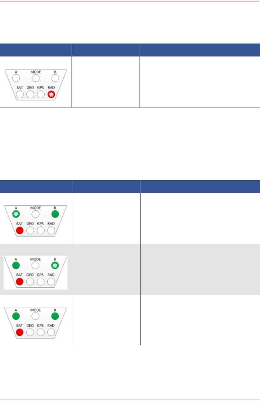
Table D–1 WRU LED Status Indications
LED Indicators Summary Description
Undeployed No lights are on; the unit is undeployed.
Geo Down Tilt Detected All LEDs are on solid
Battery test in progress Flashing:
•MODE
•BAT
Battery A in use A flashing

5Mbps Draft
R03.h RT 1000 1.5.0 Deployment Guide 101
© 2010-2012 Wireless Seismic, Inc. All rights reserved.
D. LED Indicators
Self test in progress Flashing:
•MODE
•BAT
•GEO
•GPS
•RAD
Geophone test in
progress Flashing:
•MODE
•GEO
Acquiring GPS fix Flashing:
•MODE
•GPS
Neighbor discovery in
progress Flashing:
•MODE
•RAD
Neighbor discovered Flashing:
•A
•MODE
•B
Continue (lay flat to
move to next test) Solid:
•MODE
•GEO
•GPS
NOTE: To skip a test during the self-test
process, tilt the unit vertical
(geophone down) until you see this
triangle of LEDs. Tilt the unit back to
horizontal to continue.
Table D–1 WRU LED Status Indications (cont.)
LED Indicators Summary Description
5Mbps Draft
102 RT 1000 1.5.0 Deployment Guide R03.h
© 2010-2012 Wireless Seismic, Inc. All rights reserved.
D. LED Indicators
Error LEDs remain persistent throughout the self-discovery process and are turned
off upon completion. If certain self-tests fail, it is possible that the WRU will power
down.
If a WRU self test fails, the WRU will continue to the next test.
You can skip a self-test by tipping the WRU geophone down and then returning it
to the upright position (flat on the ground).
Sleeping RAD flashing
Table D–1 WRU LED Status Indications (cont.)
LED Indicators Summary Description
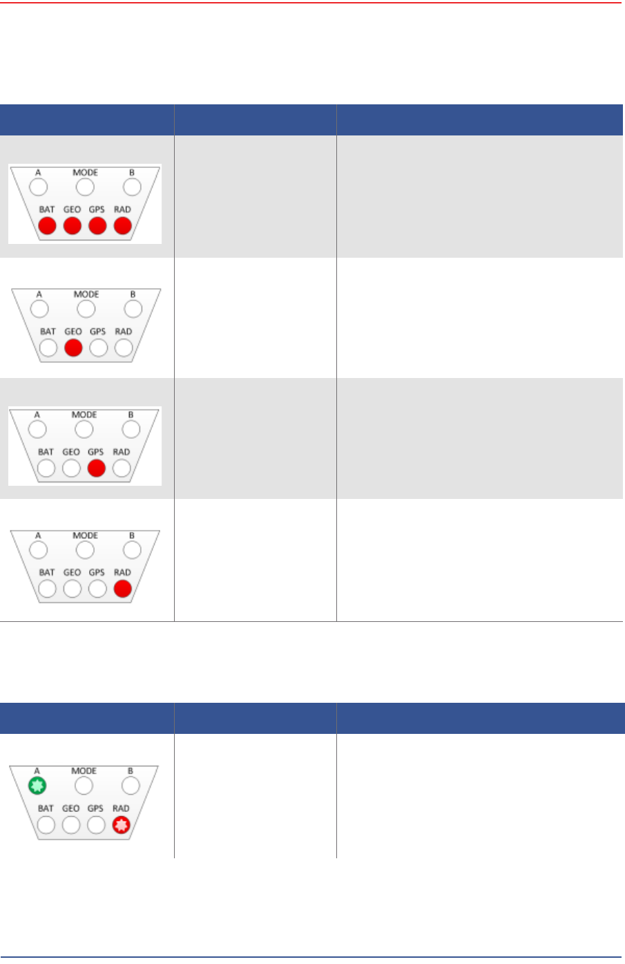
Table D–2 WRU LED Error Indications
LED Indicators Summary Description
Single battery failure
(B) A flashing
Solid:
•B
•BAT
Single battery failure
(A) B flashing
Solid:
•A
•BAT
Both batteries failure Solid:
•A
•B
•BAT
5Mbps Draft
R03.h RT 1000 1.5.0 Deployment Guide 103
© 2010-2012 Wireless Seismic, Inc. All rights reserved.
D. LED Indicators
Self test failure Solid:
•BAT
•GEO
•GPS
•RAD
Geophone failure GEO solid
No GPS fix GPS solid
GPS fix within 10 m within 1 min not found
No neighbor detected RAD solid
If this is the first WRU deployed, this is the
expected condition.
Table D–2 WRU LED Error Indications (cont.)
LED Indicators Summary Description
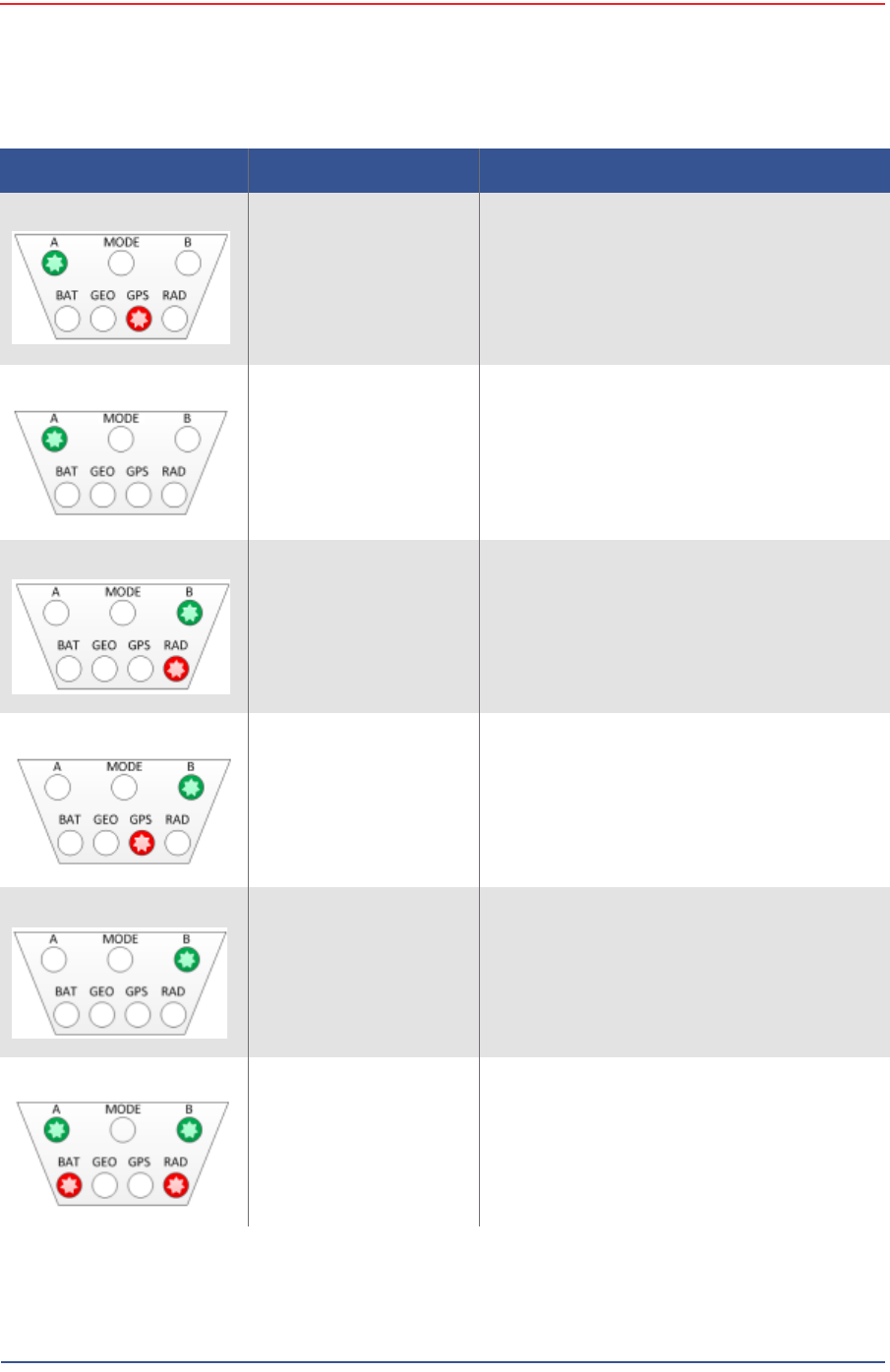
Table D–3 BSU LED Discipline Indications
LED Indicators Summary Description
Disciplining to radio Flashing:
•A
•RAD
5Mbps Draft
104 RT 1000 1.5.0 Deployment Guide R03.h
© 2010-2012 Wireless Seismic, Inc. All rights reserved.
D. LED Indicators
Disciplining to GPS Flashing:
•A
•GPS
Disciplining A flashing
Disciplined to radio Flashing:
•B
•RAD
Disciplined to GPS Flashing:
•B
•GPS
Disciplined B flashing
Incorrectly dropped out
of cycle mode Flashing:
•A
•B
•BAT
•RAD
Table D–3 BSU LED Discipline Indications (cont.)
LED Indicators Summary Description

5Mbps Draft
R03.h RT 1000 1.5.0 Deployment Guide 105
© 2010-2012 Wireless Seismic, Inc. All rights reserved.
D. LED Indicators
Armed MODE flashing
Table D–3 BSU LED Discipline Indications (cont.)
LED Indicators Summary Description

5Mbps Draft
RT 1000 1.5.0 106 Deployment Guide R03.h
© 2010-2012 Wireless Seismic, Inc. All rights reserved.
E
E. Weighted Mast
This section describes the mast that uses weights to maintain stability.
E.1 Specifications
Tripod Weight = 50 lbs (22.73 kg)
Minimum mast height = 53” (includes 6” for mounting)
Base size = 48” (1.2m) x 48” (1.2m)
Supports up to 12 – 16” x 8” blocks
Pre-galvanized steel frame
Accepts up to 2.5” mast (not included)
5Mbps Draft
R03.h RT 1000 1.5.0 Deployment Guide 107
© 2010-2012 Wireless Seismic, Inc. All rights reserved.
E. Weighted Mast
Hardware Supplied
E.2 Hardware Supplied
The following hardware is supplied with the tripod mast:
4 - Bolt, Carriage 1/4 - 20 x 3/4"
12 - Bolt, Carriage 1/4 - 20 x 5/8"
4 - Bolt, 1/4 - 20 x 3/4" Hex Head
4- Bolt, 1/4 - 20 x 1/2" Hex Head
24-Nut, 1/4 - 20
24 - Lock washer, 1/4 Int. tooth
Figure E–1 Weighted Mast
5Mbps Draft
108 RT 1000 1.5.0 Deployment Guide R03.h
© 2010-2012 Wireless Seismic, Inc. All rights reserved.
E. Weighted Mast
Assembly Instructions
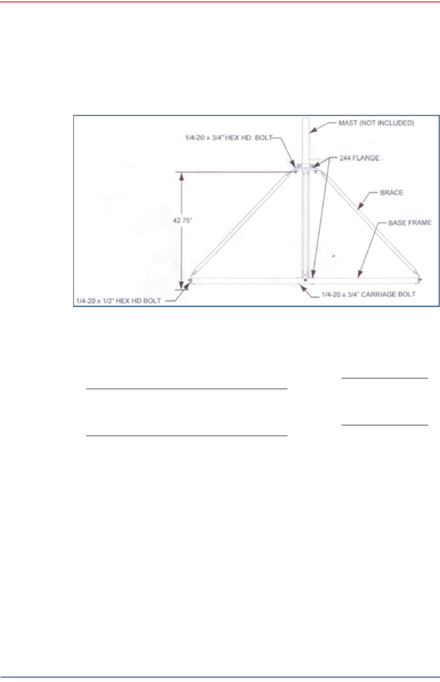
E.3 Assembly Instructions
This section provides instructions and illustrations for assembly of the tripod.
To assemble the tripod:
1Assemble one 244 Flange to the Center Support Plate using four 1/4-20 x 3/4"
carriage Bolts, Lock washers and Hex Nuts. Make sure to assemble the Bolts
with the Heads on the underside of the frame. Hex Nut should be on the top
side of the frame.
2 Assemble Base Frame and Center Support Plate using twelve 1/4-20 x 5/8"
carriage Bolts, Lock washers and Hex Nuts. Make sure to assemble the Bolts
with the Heads on the underside of the frame. Hex Nut should be on the top
side of the frame.
3Assemble the four (4) Braces to the upper support flange using four 1/4-20x3/
4 Hex Head Bolts, Lock washers and Nuts.
4Assemble the other end of the braces to the base frame using the four (4) 1/4-
20 x 1/2" Hex Head Bolts, Lock washers, and Nuts.
5Insert Bolts into upper and lower flange.
6Slide the mast (not included) into position and tighten securely and weigh.
Wade Antenna Ltd.
Ontario, Canada
Figure E–2 Tripod Assembly – Front View

5Mbps Draft
RT 1000 1.5.0 109 Deployment Guide R03.h
© 2010-2012 Wireless Seismic, Inc. All rights reserved.
Index
Numerics
192.168.0.10 40
2.4 GHz 31
24 Ah DC battery 37
4.9 GHz 39
5.1 GHz 39
5.8 GHz 31, 39
A
A 100
Acquiring GPS fix 101
antenna 12
connecting 28
specifications 39, 90
tips 28, 74
antennas 39, 90
auto-power-leveling 39
B
B 101
backhaul 31, 32, 35
backhaul masts 42
backpack 45
bag 45
base 42
tips 60
BAT 100
battery
24 V 37
charger 80
recharge 37
remove 70
specifications 75
tips 73
Battery A in use 100
Battery test in progress 100
BSU 32
Armed 105
Disciplined 104
Disciplined to GPS 104
Disciplined to radio 104
Disciplining 104
Disciplining to GPS 104
Disciplining to radio 103
error 104
kit 35
bucket-brigade 31
C
central recording truck components 33
color 40
colors 58
communication
tips 73
contact 10
Continue 101
CSS 32
D
datasheet 39
default IP address 40
down tilt detected 100
E
error
Both batteries failure 102
Geophone failure 103
No GPS fix 103
No neighbor detected 103
Self test failure 103
Single battery failure (A) 102
Single battery failure (B) 102
error indicators 100
Ethernet cable 74
example 33
deployment 64
F
FCC 90
Section 15.203 90
FM1100 40
FM3100 41
frequencies 58
G
GEO 101
geophone 27
Geophone test in progress 101
GPS 101

5Mbps Draft
Index
H
110 RT 1000 1.5.0 Deployment Guide R03.h
© 2010-2012 Wireless Seismic, Inc. All rights reserved.
disciplined 104
error 103
ground equipment 11
assemble 26
H
help 9
hopping 31
I
Industrial, Scientific, and Medical radio band 31
IP address
Fluidmesh default 40
ISM 31
L
LED status 100
LTU 31
M
mast 106
erect 59
mast kit 41
masts 42
mesh
end 56
point 56
mesh networking 31
MODE 100
modifications 90
N
Neighbor discovered 101
Neighbor discovery in progress 101
Netmask 53
network
private 46
radio 46
restore settings 59
NIC 54
node 31
P
PoE 31, 36
injector 31
switch 31
tips 73
power off WRU 68
Power over Ethernet 31
power supply 37
power-leveling 39
protective shell 38
R
RAD 101
radio
color 40
configure 46
datasheet 39
install two 63
kit 39
network configuration 46
radio band 31
radios 32
relay 31
remove battery 70
repeater 29
restore network settings 59
S
Self test in progress 101
self-test 101
SIU 33
skip a test 101
Sleeping 102
solid LEDs 100
specifications
antenna 39, 90
status
Acquiring GPS fix 101
Battery A in use 100
Battery test in progress 100
Continue 101
down tilt detected 100
Geophone test in progress 101
Neighbor discovered 101
Neighbor discovery in progress 101
Self test in progress 101
Sleeping 102
Undeployed 100
string-of-pearls 31
supported
antennas 39, 90
T
tilt 100
tripod assembly 108
U
Undeployed 100
urban environments 73
users 9
W
WRU 31
power off 68
power on 29
powers down 102
tests 30